EP3661097B1 - Verfahren zur übertragung von srs und endgerät dafür - Google Patents
Verfahren zur übertragung von srs und endgerät dafür Download PDFInfo
- Publication number
- EP3661097B1 EP3661097B1 EP18838711.2A EP18838711A EP3661097B1 EP 3661097 B1 EP3661097 B1 EP 3661097B1 EP 18838711 A EP18838711 A EP 18838711A EP 3661097 B1 EP3661097 B1 EP 3661097B1
- Authority
- EP
- European Patent Office
- Prior art keywords
- srs
- symbol
- antenna
- transmission
- information
- Prior art date
- Legal status (The legal status is an assumption and is not a legal conclusion. Google has not performed a legal analysis and makes no representation as to the accuracy of the status listed.)
- Active
Links
Images


Classifications
-
- H—ELECTRICITY
- H04—ELECTRIC COMMUNICATION TECHNIQUE
- H04L—TRANSMISSION OF DIGITAL INFORMATION, e.g. TELEGRAPHIC COMMUNICATION
- H04L5/00—Arrangements affording multiple use of the transmission path
- H04L5/0091—Signalling for the administration of the divided path, e.g. signalling of configuration information
- H04L5/0094—Indication of how sub-channels of the path are allocated
-
- H—ELECTRICITY
- H04—ELECTRIC COMMUNICATION TECHNIQUE
- H04L—TRANSMISSION OF DIGITAL INFORMATION, e.g. TELEGRAPHIC COMMUNICATION
- H04L5/00—Arrangements affording multiple use of the transmission path
- H04L5/003—Arrangements for allocating sub-channels of the transmission path
- H04L5/0048—Allocation of pilot signals, i.e. of signals known to the receiver
- H04L5/0051—Allocation of pilot signals, i.e. of signals known to the receiver of dedicated pilots, i.e. pilots destined for a single user or terminal
-
- H—ELECTRICITY
- H04—ELECTRIC COMMUNICATION TECHNIQUE
- H04B—TRANSMISSION
- H04B7/00—Radio transmission systems, i.e. using radiation field
- H04B7/02—Diversity systems; Multi-antenna system, i.e. transmission or reception using multiple antennas
- H04B7/04—Diversity systems; Multi-antenna system, i.e. transmission or reception using multiple antennas using two or more spaced independent antennas
- H04B7/06—Diversity systems; Multi-antenna system, i.e. transmission or reception using multiple antennas using two or more spaced independent antennas at the transmitting station
- H04B7/0602—Diversity systems; Multi-antenna system, i.e. transmission or reception using multiple antennas using two or more spaced independent antennas at the transmitting station using antenna switching
-
- H—ELECTRICITY
- H04—ELECTRIC COMMUNICATION TECHNIQUE
- H04B—TRANSMISSION
- H04B7/00—Radio transmission systems, i.e. using radiation field
- H04B7/02—Diversity systems; Multi-antenna system, i.e. transmission or reception using multiple antennas
- H04B7/04—Diversity systems; Multi-antenna system, i.e. transmission or reception using multiple antennas using two or more spaced independent antennas
- H04B7/06—Diversity systems; Multi-antenna system, i.e. transmission or reception using multiple antennas using two or more spaced independent antennas at the transmitting station
- H04B7/0613—Diversity systems; Multi-antenna system, i.e. transmission or reception using multiple antennas using two or more spaced independent antennas at the transmitting station using simultaneous transmission
- H04B7/0615—Diversity systems; Multi-antenna system, i.e. transmission or reception using multiple antennas using two or more spaced independent antennas at the transmitting station using simultaneous transmission of weighted versions of same signal
- H04B7/0619—Diversity systems; Multi-antenna system, i.e. transmission or reception using multiple antennas using two or more spaced independent antennas at the transmitting station using simultaneous transmission of weighted versions of same signal using feedback from receiving side
-
- H—ELECTRICITY
- H04—ELECTRIC COMMUNICATION TECHNIQUE
- H04L—TRANSMISSION OF DIGITAL INFORMATION, e.g. TELEGRAPHIC COMMUNICATION
- H04L1/00—Arrangements for detecting or preventing errors in the information received
- H04L1/02—Arrangements for detecting or preventing errors in the information received by diversity reception
- H04L1/06—Arrangements for detecting or preventing errors in the information received by diversity reception using space diversity
- H04L1/0618—Space-time coding
- H04L1/0675—Space-time coding characterised by the signaling
-
- H—ELECTRICITY
- H04—ELECTRIC COMMUNICATION TECHNIQUE
- H04L—TRANSMISSION OF DIGITAL INFORMATION, e.g. TELEGRAPHIC COMMUNICATION
- H04L5/00—Arrangements affording multiple use of the transmission path
- H04L5/003—Arrangements for allocating sub-channels of the transmission path
- H04L5/0048—Allocation of pilot signals, i.e. of signals known to the receiver
-
- H—ELECTRICITY
- H04—ELECTRIC COMMUNICATION TECHNIQUE
- H04B—TRANSMISSION
- H04B7/00—Radio transmission systems, i.e. using radiation field
- H04B7/02—Diversity systems; Multi-antenna system, i.e. transmission or reception using multiple antennas
- H04B7/04—Diversity systems; Multi-antenna system, i.e. transmission or reception using multiple antennas using two or more spaced independent antennas
- H04B7/0404—Diversity systems; Multi-antenna system, i.e. transmission or reception using multiple antennas using two or more spaced independent antennas the mobile station comprising multiple antennas, e.g. to provide uplink diversity
-
- H—ELECTRICITY
- H04—ELECTRIC COMMUNICATION TECHNIQUE
- H04L—TRANSMISSION OF DIGITAL INFORMATION, e.g. TELEGRAPHIC COMMUNICATION
- H04L25/00—Baseband systems
- H04L25/02—Details ; arrangements for supplying electrical power along data transmission lines
- H04L25/0202—Channel estimation
- H04L25/0204—Channel estimation of multiple channels
-
- H—ELECTRICITY
- H04—ELECTRIC COMMUNICATION TECHNIQUE
- H04L—TRANSMISSION OF DIGITAL INFORMATION, e.g. TELEGRAPHIC COMMUNICATION
- H04L25/00—Baseband systems
- H04L25/02—Details ; arrangements for supplying electrical power along data transmission lines
- H04L25/0202—Channel estimation
- H04L25/0224—Channel estimation using sounding signals
-
- H—ELECTRICITY
- H04—ELECTRIC COMMUNICATION TECHNIQUE
- H04L—TRANSMISSION OF DIGITAL INFORMATION, e.g. TELEGRAPHIC COMMUNICATION
- H04L5/00—Arrangements affording multiple use of the transmission path
- H04L5/0001—Arrangements for dividing the transmission path
- H04L5/0014—Three-dimensional division
- H04L5/0023—Time-frequency-space
Definitions
- the present disclosure relates to a wireless communication system, and more particularly, to a method of transmitting a sounding reference signal (SRS) and terminal therefor.
- SRS sounding reference signal
- MTC massive Machine Type Communications
- eMBB enhanced Mobile Broadband
- mMTC massive MTC
- URLLC Ultra-Reliable and Low Latency Communication
- An object of the present disclosure is to provide a method for a terminal to transmit an SRS.
- Another object of the present disclosure is to provide a terminal for transmitting an SRS.
- a method of transmitting an SRS by a user equipment (UE) as set forth in the appended claims.
- it is capable of reducing errors when SRS transmission is performed on consecutive symbols based on antenna switching operation.
- a terminal is a common name of such a mobile or fixed user stage device as a user equipment (UE), a mobile station (MS), an advanced mobile station (AMS) and the like.
- a base station (BS) is a common name of such a random node of a network stage communicating with a terminal as a Node B (NB), an eNode B (eNB), an access point (AP) and the like.
- NB Node B
- eNB eNode B
- AP access point
- a user equipment In a mobile communication system, a user equipment is able to receive information in downlink and is able to transmit information in uplink as well.
- Information transmitted or received by the user equipment node may include various kinds of data and control information.
- various physical channels may exist.
- CDMA Code Division Multiple Access
- FDMA Frequency Division Multiple Access
- TDMA Time Division Multiple Access
- OFDMA Orthogonal Frequency Division Multiple Access
- SC-FDMA Single Carrier Frequency Division Multiple Access
- CDMA may be implemented as a radio technology such as Universal Terrestrial Radio Access (UTRA) or CDMA2000.
- TDMA may be implemented as a radio technology such as Global System for Mobile communications (GSM)/General packet Radio Service (GPRS)/Enhanced Data Rates for GSM Evolution (EDGE).
- GSM Global System for Mobile communications
- GPRS General packet Radio Service
- EDGE Enhanced Data Rates for GSM Evolution
- OFDMA may be implemented as a radio technology such as IEEE 802.11 (Wi-Fi), IEEE 802.16 (WiMAX), IEEE 802.20, Evolved UTRA (E-UTRA), etc.
- UTRA is a part of Universal Mobile Telecommunications System (UMTS).
- 3GPP LTE is a part of Evolved UMTS (E-UMTS) using E-UTRA, adopting OFDMA for DL and SC-FDMA for UL.
- LTE-Advanced (LTE-A) is an evolution of 3GPP LTE.
- FIG. 1 is a block diagram for configurations of a base station 105 and a user equipment 110 in a wireless communication system 100.
- the wireless communication system 100 may include at least one base station and/or at least one user equipment.
- a base station 105 may include a transmitted (Tx) data processor 115, a symbol modulator 120, a transmitter 125, a transceiving antenna 130, a processor 180, a memory 185, a receiver 190, a symbol demodulator 195 and a received data processor 197.
- a user equipment 110 may include a transmitted (Tx) data processor 165, a symbol modulator 170, a transmitter 175, a transceiving antenna 135, a processor 155, a memory 160, a receiver 140, a symbol demodulator 155 and a received data processor 150.
- each of the base station 105 and the user equipment 110 includes a plurality of antennas. Therefore, each of the base station 105 and the user equipment 110 of the present disclosure supports an MIMO (multiple input multiple output) system. And, the base station 105 according to the present disclosure may support both SU-MIMO (single user-MIMO) and MU-MIMO (multi user-MIMO) systems.
- MIMO multiple input multiple output
- the base station 105 according to the present disclosure may support both SU-MIMO (single user-MIMO) and MU-MIMO (multi user-MIMO) systems.
- the transmitted data processor 115 receives traffic data, codes the received traffic data by formatting the received traffic data, interleaves the coded traffic data, modulates (or symbol maps) the interleaved data, and then provides modulated symbols (data symbols).
- the symbol modulator 120 provides a stream of symbols by receiving and processing the data symbols and pilot symbols.
- the symbol modulator 120 multiplexes the data and pilot symbols together and then transmits the multiplexed symbols to the transmitter 125.
- each of the transmitted symbols may include the data symbol, the pilot symbol or a signal value of zero.
- pilot symbols may be contiguously transmitted.
- the pilot symbols may include symbols of frequency division multiplexing (FDM), orthogonal frequency division multiplexing (OFDM), or code division multiplexing (CDM).
- the transmitter 125 receives the stream of the symbols, converts the received stream to at least one or more analog signals, additionally adjusts the analog signals (e.g., amplification, filtering, frequency upconverting), and then generates a downlink signal suitable for a transmission on a radio channel. Subsequently, the downlink signal is transmitted to the user equipment via the antenna 130.
- analog signals e.g., amplification, filtering, frequency upconverting
- the receiving antenna 135 receives the downlink signal from the base station and then provides the received signal to the receiver 140.
- the receiver 140 adjusts the received signal (e.g., filtering, amplification and frequency downconverting), digitizes the adjusted signal, and then obtains samples.
- the symbol demodulator 145 demodulates the received pilot symbols and then provides them to the processor 155 for channel estimation.
- the symbol demodulator 145 receives a frequency response estimated value for downlink from the processor 155, performs data demodulation on the received data symbols, obtains data symbol estimated values (i.e., estimated values of the transmitted data symbols), and then provides the data symbols estimated values to the received (Rx) data processor 150.
- the received data processor 150 reconstructs the transmitted traffic data by performing demodulation (i.e., symbol demapping, deinterleaving and decoding) on the data symbol estimated values.
- the processing by the symbol demodulator 145 and the processing by the received data processor 150 are complementary to the processing by the symbol modulator 120 and the processing by the transmitted data processor 115 in the base station 105, respectively.
- the transmitted data processor 165 processes the traffic data and then provides data symbols.
- the symbol modulator 170 receives the data symbols, multiplexes the received data symbols, performs modulation on the multiplexed symbols, and then provides a stream of the symbols to the transmitter 175.
- the transmitter 175 receives the stream of the symbols, processes the received stream, and generates an uplink signal. This uplink signal is then transmitted to the base station 105 via the antenna 135.
- the uplink signal is received from the user equipment 110 via the antenna 130.
- the receiver 190 processes the received uplink signal and then obtains samples.
- the symbol demodulator 195 processes the samples and then provides pilot symbols received in uplink and a data symbol estimated value.
- the received data processor 197 processes the data symbol estimated value and then reconstructs the traffic data transmitted from the user equipment 110.
- the processor 155/180 of the user equipment/base station 110/105 directs operations (e.g., control, adjustment, management, etc.) of the user equipment/base station 110/105.
- the processor 155/180 may be connected to the memory unit 160/185 configured to store program codes and data.
- the memory 160/185 is connected to the processor 155/180 to store operating systems, applications and general files.
- the processor 155/180 may be called one of a controller, a microcontroller, a microprocessor, a microcomputer and the like. And, the processor 155/180 may be implemented using hardware, firmware, software and/or any combinations thereof. In the implementation by hardware, the processor 155/180 may be provided with such a device configured to implement the present disclosure as ASICs (application specific integrated circuits), DSPs (digital signal processors), DSPDs (digital signal processing devices), PLDs (programmable logic devices), FPGAs (field programmable gate arrays), and the like.
- ASICs application specific integrated circuits
- DSPs digital signal processors
- DSPDs digital signal processing devices
- PLDs programmable logic devices
- FPGAs field programmable gate arrays
- the firmware or software may be configured to include modules, procedures, and/or functions for performing the above-explained functions or operations of the present disclosure. And, the firmware or software configured to implement the present disclosure is loaded in the processor 155/180 or saved in the memory 160/185 to be driven by the processor 155/180.
- Layers of a radio protocol between a user equipment/base station and a wireless communication system may be classified into 1st layer L1, 2nd layer L2 and 3rd layer L3 based on 3 lower layers of OSI (open system interconnection) model well known to communication systems.
- a physical layer belongs to the 1st layer and provides an information transfer service via a physical channel.
- RRC (radio resource control) layer belongs to the 3rd layer and provides control radio resourced between UE and network.
- a user equipment and a base station may exchange RRC messages with each other through a wireless communication network and RRC layers.
- the processor 155/180 of the user equipment/base station performs an operation of processing signals and data except a function for the user equipment/base station 110/105 to receive or transmit a signal
- the processors 155 and 180 will not be mentioned in the following description specifically.
- the processor 155/180 can be regarded as performing a series of operations such as a data processing and the like except a function of receiving or transmitting a signal without being specially mentioned.
- Table 1 below shows details of SRS transmission in the 3GPP LTE/LTE-A system.
- a UE shall transmit Sounding Reference Symbol (SRS) on per serving cell SRS resources based on two trigger types: - trigger type 0: higher layer signalling - trigger type 1: DCI formats 0/4/1A for FDD and TDD and DCI formats 2B/2C/2D for TDD.
- SRS Sounding Reference Symbol
- a UE may be configured with SRS parameters for trigger type 0 and trigger type 1 on each serving cell.
- SRS parameters are serving cell specific and semi-statically configurable by higher layers for trigger type 0 and for trigger type 1.
- - Transmission comb k TC as defined in subclause 5.5.3.2 of [3] for trigger type 0 and each configuration of trigger type 1 -
- Starting physical resource block assignment n RRC as defined in subclause 5.5.3.2 of [3] for trigger type 0 and each configuration of trigger type 1 - duration: single or indefinite (until disabled), as defined in [11] for trigger type 0 - srs-ConfigIndex I SRS for SRS periodicity T SRS and SRS subframe offset T offset , as defined in Table 8.2-1 and Table 8.2-2 for trigger type 0 and SRS periodicity T SRS,1 ,and SRS subframe offset T SRS,1 , as defined in Table 8.2-4 and Table 8.2-5 trigger type 1 - SRS bandwidth B SRS , as defined in subclause 5.5.3.2 of [3] for trigger type 0 and each configuration of trigger type 1 - Fre
- the 2-bit SRS request field [4] in DCI format 4 indicates the SRS parameter set given in Table 8.1-1.
- a single set of SRS parameters srs-ConfigApDCI-Format0
- a single common set of SRS parameters srs-ConfigApDCI-Format1a2b2c
- the SRS request field is 1 bit [4] for DCI formats 0/1A/2B/2C/2D, with a type 1 SRS triggered if the value of the SRS request field is set to '1'.
- a 1-bit SRS request field shall be included in DCI formats 0/1A for frame structure type 1 and 0/1A/2B/2C/2D for frame structure type 2 if the UE is configured with SRS parameters for DCI formats 0/1A/2B/2C/2D by higher-layer signalling.
- Table 2 below shows SRS request values for trigger type 1 of DCI format 4 in the 3GPP LTE/LTE-A system.
- Table 3 below shows additional details of the SRS transmission in the 3GPP LTE/LTE-A system.
- the serving cell specific SRS transmission bandwidths C SRS are configured by higher layers.
- the allowable values are given in subclause 5.5.3.2 of [3].
- the serving cell specific SRS transmission sub-frames are configured by higher layers.
- the allowable values are given in subclause 5.5.3.3 of [3].
- SRS transmissions can occur in UpPTS and uplink subframes of the UL/DL configuration indicated by the higher layer parameter subframeAssignment for the serving cell.
- N p ⁇ ⁇ 0,1,2,4 ⁇ and for PUSCH transmission mode 2 N p ⁇ ⁇ 0,1,2 ⁇ with two antenna ports configured for PUSCH and N p ⁇ ⁇ 0,1,4 ⁇ with 4 antenna ports configured for PUSCH.
- a UE configured for SRS transmission on multiple antenna ports of a serving cell shall transmit SRS for all the configured transmit antenna ports within one SC-FDMA symbol of the same subframe of the serving cell.
- the SRS transmission bandwidth and starting physical resource block assignment are the same for all the configured antenna ports of a given serving cell.
- a UE not configured with multiple TAGs shall not transmit SRS in a symbol whenever SRS and PUSCH transmissions happen to overlap in the same symbol.
- TDD serving cell when one SC-FDMA symbol exists in UpPTS of the given serving cell, it can be used for SRS transmission.
- both SC-FDMA symbols exist in UpPTS of the given serving cell both can be used for SRS transmission and for trigger type 0 SRS both can be assigned to the same UE.
- a UE is not configured with multiple TAGs, or if a UE is configured with multiple TAGs and SRS and PUCCH format 2/2a/2b happen to coincide in the same subframe in the same serving cell, -The UE shall not transmit type 0 triggered SRS whenever type 0 triggered SRS and PUCCH format 2/2a/2b transmissions happen to coincide in the same subframe; -The UE shall not transmit type 1 triggered SRS whenever type 1 triggered SRS and PUCCH format 2a/2b or format 2 with HARQ-ACK transmissions happen to coincide in the same subframe; -The UE shall not transmit PUCCH format 2 without HARQ-ACK whenever type 1 triggered SRS and PUCCH format 2 without HARQ-ACK transmissions happen to coincide in the same subframe.
- a UE is not configured with multiple TAGs, or if a UE is configured with multiple TAGs and SRS and PUCCH happen to coincide in the same subframe in the same serving cell, -The UE shall not transmit SRS whenever SRS transmission and PUCCH transmission carrying HARQ-ACK and/or positive SR happen to coincide in the same subframe if the parameter ackNackSRS-SimultaneousTransmission is FALSE; -For FDD-TDD and primary cell frame structure 1, the UE shall not transmit SRS in symbol whenever SRS transmission and PUCCH transmission carrying HARQ-ACK and/or positive SR using shortened format as defined in subclauses 5.4.1 and 5.4.2A of [3] happen to overlap in the same symbol if the parameter ackNackSRS-SimultaneousTransmission is TRUE.
- the UE shall transmit SRS whenever SRS transmission and PUCCH transmission carrying HARQ-ACK and/or positive SR using shortened format as defined in subclauses 5.4.1 and 5.4.2A of [3] happen to coincide in the same subframe if the parameter ackNackSRS-SimultaneousTransmission is TRUE.
- a UE not configured with multiple TAGs shall not transmit SRS whenever SRS transmission on any serving cells and PUCCH transmission carrying HARQ-ACK and/or positive SR using normal PUCCH format as defined in subclauses 5.4.1 and 5.4.2A of [3] happen to coincide in the same subframe.
- the UE In UpPTS, whenever SRS transmission instance overlaps with the PRACH region for preamble format 4 or exceeds the range of uplink system bandwidth configured in the serving cell, the UE shall not transmit SRS.
- the parameter ackNackSRS-SimultaneousTransmission provided by higher layers determines if a UE is configured to support the transmission of HARQ-ACK on PUCCH and SRS in one subframe.
- the cell specific SRS subframes of the primary cell UE shall transmit HARQ-ACK and SR using the shortened PUCCH format as defined in subclauses 5.4.1 and 5.4.2A of [3], where the HARQ-ACK or the SR symbol corresponding to the SRS location is punctured.
- This shortened PUCCH format shall be used in a cell specific SRS subframe of the primary cell even if the UE does not transmit SRS in that subframe.
- the cell specific SRS subframes are defined in subclause 5.5.3.3 of [3].
- the UE shall use the normal PUCCH format 1/1a/1b as defined in subclause 5.4.1 of [3] or normal PUCCH format 3 as defined in subclause 5.4.2A of [3] for the transmission of HARQ-ACK and SR.
- Trigger type 0 SRS configuration of a UE in a serving cell for SRS periodicity, T SRS , and SRS subframe offset, T offset is defined in Table 8.2-1 and Table 8.2-2, for FDD and TDD serving cell, respectively.
- the periodicity T SRS of the SRS transmission is serving cell specific and is selected from the set ⁇ 2, 5, 10, 20, 40, 80, 160, 320 ⁇ ms or subframes.
- T SRS For the SRS periodicity T SRS of 2 ms in TDD serving cell, two SRS resources are configured in a half frame containing UL subframe(s) of the given serving cell.
- the UE For TDD serving cell, and a UE configured for type 0 triggered SRS transmission in serving cell c, and the UE configured with the parameter EIMTA-MainConfigServCell-r12 for serving cell c, if the UE does not detect an UL/DL configuration indication for radio frame m (as described in section 13.1), the UE shall not transmit trigger type 0 SRS in a subframe of radio frame m that is indicated by the parameter eimta-HarqReferenceConfig-r12 as downlink subframe unless the UE transmits PUSCH in the same subframe.
- a Trigger type 1 SRS configuration of a UE in a serving cell for SRS periodicity, T SRS,1 , and SRS subframe offset, T offset,1 is defined in Table 8.2-4 and Table 8.2-5, for FDD and TDD serving cell, respectively.
- the periodicity T SRS,1 of the SRS transmission is serving cell specific and is selected from the set ⁇ 2, 5, 10 ⁇ ms or subframes.
- a UE configured for type 1 triggered SRS transmission in serving cell c and not configured with a carrier indicator field shall transmit SRS on serving cell c upon detection of a positive SRS request in PDCCH/EPDCCH scheduling PUSCH/PDSCH on serving cell c.
- a UE configured for type 1 triggered SRS transmission in serving cell c and configured with a carrier indicator field shall transmit SRS on serving cell c upon detection of a positive SRS request in PDCCH/EPDCCH scheduling PUSCH/PDSCH with the value of carrier indicator field corresponding to serving cell c.
- a UE configured for type 1 triggered SRS transmission is not expected to receive type 1 SRS triggering events associated with different values of trigger type 1 SRS transmission parameters, as configured by higher layer signalling, for the same subframe and the same serving cell.
- the UE shall not transmit SRS in a subframe of a radio frame that is indicated by the corresponding eIMTA-UL/DL-configuration as a downlink subframe.
- a UE shall not transmit SRS whenever SRS and a PUSCH transmission corresponding to a Random Access Response Grant or a retransmission of the same transport block as part of the contention based random access procedure coincide in the same subframe.
- Table 4 below shows the subframe offset configuration (T offset ) and UE-specific SRS periodicity (T SRS ) for trigger type 0 in FDD.
- SRS Configuration Index I SRS SRS Periodicity (ms) SRS Subframe Offset 0 - 1 2 I SRS 2 - 6 5 I SRS - 2 7 - 16 10 I SRS - 7 17 - 36 20 I SRS - 17 37 - 76 40 I SRS - 37 77 - 156 80 I SRS - 77 157 - 316 160 I SRS - 157 317 - 636 320 I SRS - 317 637 - 1023 reserved reserved
- Table 5 shows the subframe offset configuration (T offset ) and UE-specific SRS periodicity (T SRS ) for trigger type 0 in TDD.
- SRS Configuration Index I SRS SRS Periodicity (ms) SRS Subframe Offset 0 - 1 2 I SRS 2 - 6 5 I SRS - 2 7 - 16 10 I SRS - 7 17 - 36 20 I SRS -17 37 - 76 40 I SRS - 37 77 - 156 80 I SRS -77 157 - 316 160 I SRS - 157 317 - 636 320 I SRS -317 637 - 1023 reserved reserved [Table 6]
- SRS Configuration Index I SRS SRS Periodicity (ms) SRS Subframe Offset 0 2 0, 1 1 2 0, 2 2 2 1, 2 3 2 0, 3 4 2 1, 3 5 2 0, 4 6 2 1, 4 7 2 2, 3 8 2 2, 4 9 2 3, 4 10 - 14 5 I SRS - 10 15 - 24 10 I SRS
- Table 7 shows k SRS for TDD.
- subframe index n 0 1 2 3 4 5 6 7 8 9 1st symbol of UpPTS 2nd symbol of UpPTS 1st symbol of UpPTS 2nd symbol of UpPTS k SRS in case UpPTS length of 2 symbols 0 1 2 3 4 5 6 7 8 9 k SRS in case UpPTS length of 1 symbol 1 2 3 4 6 7 8 9
- Table 8 shows the subframe offset configuration (T offset,1 ) and UE-specific SRS periodicity (T SRS,1 ) for trigger type 1 in FDD.
- SRS Configuration Index I SRS SRS Periodicity (ms) SRS Subframe Offset 0 - 1 2 I SRS 2 - 6 5 I SRS - 2 7 - 16 10 I SRS - 7 17 - 31 reserved reserved reserved
- Table 9 shows the subframe offset configuration (T offset,1 ) and UE-specific SRS periodicity (T SRS,1 ) for trigger type 1 in TDD.
- SRS Configuration Index I SRS SRS Periodicity (ms) SRS Subframe Offset 0 reserved reserved 1 2 0, 2 2 2 1, 2 3 2 0, 3 4 2 1, 3 5 2 0, 4 6 2 1, 4 7 2 2, 3 8 2 2, 4 9 2 3, 4 10 - 14 5 I SRS - 10 15 - 24 10 I SRS - 15 25 - 31 reserved reserved reserved
- mmW millimeter wave
- a short wavelength is used, and thus a plurality of antennas elements can be installed in the same area.
- the wavelength in the 30 GHz band is 1 cm, and accordingly a total of 64 (8x8) antenna elements may be installed at intervals of 0.5 lambda (wavelength) in a 2-dimensional array on a 4 by 4 cm panel. Therefore, in the mmW system, multiple antenna elements may be used to increase the beamforming (BF) gain to enhance the coverage or the throughput.
- BF beamforming
- each antenna element is provided with a transceiver unit (TXRU) to enable adjustment of transmit power and phase per antenna element, independent beamforming may be performed for each frequency resource.
- TXRU transceiver unit
- installing TXRUs in all the 100 antenna elements is less feasible in terms of cost. Therefore, a method of mapping a plurality of antenna elements to one TXRU and adjusting the direction of a beam using an analog phase shifter has been considered.
- this analog beamforming technique is disadvantageous in that frequency selective beamforming is not allowed because only one beam direction can be created over the full band.
- hybrid BF with B TXRUs which are fewer than Q antenna elements may be considered.
- the number of directions in which beams are allowed to be transmitted at the same time is limited to B or less, though it depends on how the B TXRUs and Q antenna elements are connected.
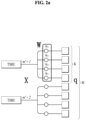
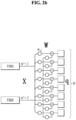
- FIG. 2A is a diagram illustrating TXRU virtualization model option 1 (a sub-array model), and FIG. 2B is a diagram illustrating TXRU virtualization model option 2 (a full connection model).
- FIGs. 2A and 2B show representative examples of a method for connection of a TXRU and an antenna element.
- the TXRU virtualization model shows the relationship between the output signal of the TXRU and the output signal of the antenna elements.
- FIG. 2A illustrates a scheme in which a TXRU is connected to a sub-array. In this case, the antenna elements are connected to only one TXRU.
- FIG. 2B illustrates a scheme in which a TXRU is connected to all antenna elements. In this case, the antenna elements are connected to all TXRUs.
- W denotes a phase vector multiplied by an analog phase shifter. That is, the direction of analog beamforming is determined by W.
- the mapping between the CSI-RS antenna ports and the TXRUs may be 1-to-1 or 1-to-many mapping.
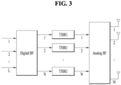
- FIG. 3 is a block diagram for hybrid beamforming.
- analog beamforming refers to an operation of performing precoding (or combining) in the RF stage.
- each of the baseband stage and the RF stage may use precoding (or combining), thereby reducing the number of RF chains and the number of D/A (or a A/D) converters and exhibiting performance close to that of digital beamforming.
- the hybrid beamforming structure may be represented by N transceiver units (TXRU) and M physical antennas for simplicity.
- the digital beamforming for the L data layers to be transmitted from the transmitting side may be represented by an N by L matrix, and then N converted digital signals are converted into analog signals through the TXRUs and then subjected to analog beamforming represented by an M by N matrix.
- FIG. 3 is a schematic diagram of a hybrid beamforming structure in terms of the TXRU and physical antennas.
- the number of digital beams is L
- the number of analog beams is N.
- the New RAT system it is considered to design the base station to change analog beamforming on a symbol-by-symbol basis to support more efficient beamforming for a UE located in a specific area.
- N TXRUs and M RF antennas are defined as one antenna panel in FIG. 3
- the New RAT system may introduce a plurality of antenna panels to which independent hybrid beamforming is applicable.
- an analog beam which is advantageous for signal reception may differ among the UEs, and therefore a beam sweeping operation in which the BS changes a plurality of analog beams to be applied in a specific subframe (SF) on a symbol-by-symbol basis to allow all UEs to have a reception occasion may be considered.
- SF subframe
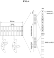
- FIG. 4 is a diagram illustrating an example of beams mapped to BRS symbols in hybrid beamforming.
- FIG. 4 illustrates the beam sweeping operation for a synchronization signal and system information in a downlink (DL) transmission process.
- a physical resource (or physical channel) on which the system information of the New RAT system is transmitted in a broadcast manner is referred to as a xPBCH (physical broadcast channel).
- Analog beams belonging to different antenna panels within one symbol may be transmitted simultaneously, and introduction of a beam RS (BRS) may be considered.
- the BRS is a reference signal (RS) transmitted by applying a single analog beam (corresponding to a specific antenna panel) as shown in FIG. 4 to measure a channel for each analog beam.
- the BRS may be defined for a plurality of antenna ports, and each antenna port of the BRS may correspond to a single analog beam.
- the RS used to measure a beam is referred to as BRS in FIG. 4 , it may be called by another name.
- the synchronization signal or the xPBCH may be transmitted by applying all analog beams in an analog beam group such that any UE can receive the synchronization signal or the xPBCH well.
- FIG. 5 is an exemplary diagram illustrating symbol/sub-symbol alignment between different numerologies.
- NR subcarrier spacing is expressed as (2n ⁇ 15) kHz, where n is an integer. From the nested perspective, the above-mentioned subset or a superset (at least 15, 30, 60, 120, 240, and 480 kHz) is considered as the main subcarrier spacing. Symbol or sub-symbol alignment between different numerologies is supported by adjusting the numerologies to have the same CP overhead rate.
- numerology is determined in a structure in which the above-described time/frequency granularity is dynamically allocated according to the respective services (eMBB, URLLC, mMTC) and scenarios (high speed, etc.).
- Tables 10 and 11 show a sequence generation method using a cell ID and a root value in the LTE system.
- Sequence-group hopping for PUSCH can be disabled for a certain UE through the higher-layer parameter Disable-sequence-group-hopping despite being enabled on a cell basis unless the PUSCH transmission corresponds to a Random Access Response Grant or a retransmission of the same transport block as part of the contention based random access procedure.
- the sequence-shift pattern f ss definition differs between PUCCH, PUSCH and SRS.
- the parameter Sequence-hopping-enabled provided by higher layers determines if sequence hopping is enabled or not.
- Sequence hopping for PUSCH can be disabled for a certain UE through the higher-layer parameter Disable-sequence-group-hopping despite being enabled on a cell basis unless the PUSCH transmission corresponds to a Random Access Response Grant or a retransmission of the same transport block as part of the contention based random access procedure.
- n SRS denotes a hopping interval in the time domain
- N b denotes the number of branches allocated to a tree level b, where b may be determined by setting(configuring) B SRS in dedicated RRC.
- the LTE hopping pattern parameter may also be set through UE-specific RRC signaling.
- some parameters may be configured as follows:
- n SRS n SRS mod 2
- n SRS n SRS mod 4
- n SRS ⁇ n SRS + ⁇ ⁇ n SRS / 4 ⁇ + ⁇ ⁇ ⁇ n SRS / K ⁇ mod 4 when K is even
- K is defined as the minim number of SRS transmissions required to cover the total UL BW using the SRS.
- n SRS First part of SRS bandwidth Second part of SRS bandwidth Third part of SRS bandwidth Fourth part of SRS bandwidth 0
- Antenna index 0 1
- Antenna index 1 2 Antenna index 2 3
- Antenna index 3 4 Antenna index 1 5
- Antenna index 2 6 Antenna index 3 7
- Antenna index 3 10 Antenna index 0 11
- Antenna index 1 12 Antenna index 3 13 Antenna index 0 14
- antenna switching may be required depending on UE RF capability if sounding is necessary.
- a transition time during which the power level changes due to antenna switching is within a CP, there is no problem.
- the transition time is out of the CP and SRS transmission is performed on consecutive symbols, an error may occur during sounding.
- the present disclosure proposes a method of transmitting an SRS in symbols, mini-slots, or slots.
- FIG. 7 is a diagram illustrating distortions caused by antenna switching.
- FIG. 7 (a) shows a magnitude distortion
- FIG. 7 (b) shows a phase distortion
- the signal distortion phenomenon during RF switching was researched using a wireless open-access research platform (WARP) FPGA board (by Rice University and Mango Communications).
- the target band was 2.4 GHz, and the transition time was represented by the period taken from 90 % of the magnitude of port A to 90 % of the magnitude of port B when switching from port A to port B.
- the transition time was estimated at about 1.2 us, and the performance was degraded by the signal distortions.
- FIG. 8 is a diagram illustrating performance degradation caused by antenna switching.
- the transition time depending on antenna switching is estimated at about 5 us.
- the CP length is determined as about 4.6875 us.
- the last symbol of a subframe is allocated as an SRS transmission resource, it may be known that no consecutive symbols are allocated as the SRS transmission resource.
- the transition time is within the CP even if antenna switching is applied between symbols, no impairment is considered regarding antenna switching for SRS transmission.
- the SRS transmission is configured on or across multiple symbols (1, 2, or 4 symbols), and the numerology is a multiple of 15 kHz.
- the numerology is a multiple of 15 kHz.
- if the SRS transmission is configured across consecutive symbols and in SRS transmission there may be a distortion in an SRS symbol based on antenna switching, and accordingly, an error may occur for UL beam management or UL/DL CSI acquisition.
- such UEs need to perform the SRS transmission depending on their RF switching capabilities.
- the present disclosure describes a method of reporting UEs' RF capabilities and configuring SRS transmission based thereon. It is assumed in the present disclosure that the NR supports not only antenna switching for SRS transmission on one carrier but also at least 2Tx switching or 4Tx switching.
- the term “antenna” may be referred to as “antenna port”, “port”, etc.
- a BS allows a UE capable of performing antenna switching for SRS transmission to transmit an SRS in or over a plurality of symbols. That is, when the BS sets an n-th symbol as a symbol for the SRS transmission for the UE performing SRS switching (i.e., the antenna switching for the SRS transmission), the BS empties an (n+1)-th symbol, which corresponds to the next symbol of the n-th symbol, or a next sub-symbol and set or allocate an (n+2)-th symbol, which corresponds to the second next symbol, or a second next sub-symbol as the symbol for the SRS transmission (the sub-symbol refers to a symbol smaller than a reference symbol, which is generated by a change in the numerology).
- the above configuration or allocation made by the BS is basically UE-specific.
- FIG. 9 is a diagram illustrating an example of providing an SRS symbol index for antenna switching for SRS transmission.
- the BS provides the UE with the index of a symbol to which the SRS is allocated among multiple symbols. For example, when the BS configures four SRS symbols starting from the n-th symbol, the BS transmits information indicating that the indexes of symbols for the SRS transmission are n and n+2 to the UE supporting the antenna switching for the SRS transmission as shown in FIG. 9 (a) . In contrast, the BS transmits information indicating that the indexes of the symbols for the SRS transmission are n+1 and n+3 to the UE as shown in FIG. 9 (b) .
- the BS may provide the UE with a flag indicating whether a symbol is empty due to the antenna switching for the SRS transmission.
- the BS may inform the UE of symbols to which the SRS is allocated in the form of a bitmap. Accordingly, the UE may recognize the allocated SRS symbols based on the bitmap. For example, when the BS transmits a bitmap of ⁇ 1010', the UE may recognize that among four SRS symbols, the first and third symbols in the time domain are allocated for the SRS transmission.
- a BS may determine whether to empty a symbol(s) between allocated or indicated SRS symbols depending on the numerology or UE RF switching capability.
- the BS may provide the UE with information indicating whether the symbol between the SRS symbols is empty, that is, no data is loaded therein.
- the BS may provide the above information to the UE through RRC signaling (Layer 3 signaling), medium access control channel element (MAC CE) signaling (Layer 2 signaling), DCI signaling (Layer 1 signaling), etc.
- RRC signaling Layer 3 signaling
- MAC CE medium access control channel element
- Layer 2 signaling medium access control channel element
- DCI signaling Layer 1 signaling
- the BS may enable a configuration flag for emptying the symbol between the SRS symbols allocated to the UE and inform the UE that the configuration flag is enabled.
- the BS may disable the configuration flag for emptying the symbol between the SRS symbols allocated to the UE and inform the UE that the configuration flag is disabled.
- a BS provides information on ports (or antenna ports) mapped to allocated SRS symbols to a UE performing antenna switching for SRS transmission.
- a port or antenna port for SRS transmission may be referred to as an SRS port.
- An SRS port value (index) may be implicitly determined, or the UE may obtain the SRS port value (index) in an implicit manner.
- the mapped port may be determined based on the SRS symbol index.
- the port may be determined by the index of a slot/mini-slot in which the SRS is configured. For example, SRS port 1 may be mapped to a symbol n, and SRS port 2 may be mapped to a symbol (n+1).
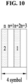
- FIG. 10 is a diagram illustrating antenna switching for SRS transmission based on a predetermined SRS port order.
- An SRS port(s) may be mapped to respective SRS symbol(s) based on the predetermined order, which is configured by RRC, etc. For example, when the number of ports mapped to one symbol is 1 and a number of SRS ports is two, and a number of SRS symbols is four, if the port indexes are determined as shown in Table 15, this may be represented as shown in FIG. 10 .
- a BS may need to allocate the SRS to the first and third symbols among the four symbols and empty the second and fourth symbols.
- the BS may transmit the value (index) of the SRS port mapped to the SRS symbol explicitly through DCI, RRC signaling, MAC CE signaling, etc.
- SRS mapping rules for mapping the SRS to SRS symbol(s) may be configured by higher layers, and the BS may transmit information about the SRS mapping rules to the UE through higher layer signaling. After selectin one of the SRS mapping rules, the BS may inform the UE of the selected mapping rule through DCI.
- Table 16 shows SRS port mapping order configurations and mapping orders based on the number of SRS ports in the case of the antenna switching for the SRS transmission.
- the port numbers of SRS ports sequentially mapped to SRS symbols in the time domain are 2 and 1 (in this case, a number of SRS symbols is four, but the SRS is allocated to the first and third symbols for antenna switching operation).
- the BS provides information on SRS transmission resources in an SRS symbol to the UE and information on SRS ports mapped to respective SRS transmission resource(s). Due to the switching, allocatable ports may be mapped to the allocated SRS transmission resources when the SRS resources are configured. For example, when SRS port numbers (SRS port values, SRS port indexes, etc.) are 1, 2, 3, and 4, ports 1 and 3 are simultaneously transmitted, and ports 2 and 4 are simultaneously transmitted.
- the UE does not simultaneously transmit SRSs on ports between the two port pairs ( ⁇ 1,3 ⁇ and ⁇ 2,4 ⁇ ) (for example, ports 1 and 2) based on antenna switching.
- each SRS port respectively mapped to each SRS transmission resource may be port 1 and/or port 3. In this case, if port 1 or port 3 is mapped to one SRS transmission resource in one SRS symbol, the other SRS resource is not used for port 2 or port 4.
- Table 17 shows an SRS port mapping order based on antenna switching when the number of SRS symbols is 4.
- FIG. 11 is a diagram illustrating SRS resource configurations and SRS port mapping rules based on antenna switching for SRS transmission.
- FIG. 11 (a) and (b) corresponds to an SRS port number.
- the BS may allocate the SRS to the second and fourth symbols as shown in FIG. 11 (a) .
- the BS may allocate the SRS to the second and fourth symbols as shown in FIG. 11 (b) .
- K 8 (four SRS allocation symbols + four empty symbols) (that is, the antenna switching is performed four times).
- the number of symbols required for SRS port mapping based on the antenna switching for the SRS transmission, K is more than the number of SRS symbols allocated to one slot, N (K>N), the port mapping may be performed as follows.
- FIG. 12 is a diagram illustrating SRS port to SRS symbol mapping in consideration of antenna switching across consecutive SRS slots (for example, SRS slot 1, SRS slot 2, etc.).
- the number of an SRS port mapped to respectively SRS symbol is implicitly determined.
- the SRS port value may be implicitly determined based on a symbol index and/or a slot index in which the SRS is configured. For example, the implicit determination may be made according to Equation 2 below.
- p SRS ⁇ n s T SRS ⁇ ⁇ N SRS _ sym + ⁇ n symbol 2 ⁇ mod 4
- T SRS denotes a SRS triggering period expressed by a unit of a slot(s) where the SRS is configured
- n S denotes a slot index
- N SRS_sym denotes the number of SRS allocation symbols in a slot where the SRS(s) is(are) triggered
- n symbol denotes a symbol index.
- the number of SRS ports is set to 4. When the number of SRS symbols in each SRS slot is set to 4, if an SRS port is mapped to an SRS symbol according to Equation 2, it may be represented as shown in FIG. 12 . The UE may implicitly obtain the number of an SRS port mapped to each SRS symbol based on Equation 2.
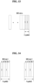
- FIG. 13 is a diagram illustrating a predefined SRS port mapping method based on the number of SRS symbols and a numerology configuration.
- the number of an SRS port mapped to each SRS symbol may be determined depending on the number of symbols in a configured SRS slot, the number of SRS ports, and/or different numerologies.
- SRS slot n when a specific UE is configured with two symbols in an SRS slot (SRS slot n) and the two symbols are configured for UL beam management by extending the SCS from 15 kHz to 30 kHz, if SRS port mapping in this SRS slot is configured by considering SRS switching, SRS sub-symbols and SRS ports mapped thereto may be determined as shown in FIG. 13 .
- FIG. 14 is a diagram illustrating explicit SRS port to SRS symbol mapping.
- a BS may explicitly transmit information on the number (value or index) of an SRS port mapped to each SRS symbol to a UE.
- the BS may provide the SRS symbol index and the SRS port number index corresponding to the SRS symbol index through Layer 1 (e.g., DCI) signaling or Layer 3 (e.g., RRC) signaling.
- Layer 1 e.g., DCI
- Layer 3 e.g., RRC
- the BS may indicate to the UE that the number of an SRS port mapped to SRS symbol n in SRS slot 1, the number of an SRS port mapped to SRS symbol n+2 in SRS slot 1, the number of an SRS port mapped to SRS symbol n in SRS slot 2, and the number of an SRS port mapped to SRS symbol n+2 in SRS slot 2 are 2, 1, 1, 2, respectively.
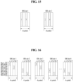
- FIG. 15 is a diagram illustrating explicit SRS port to SRS symbol mapping (SRS port group transmission).
- a BS may designate an SRS port group number and SRS ports mapped to a corresponding SRS slot and then inform a UE of the SRS port group number and the SRS ports mapped to the corresponding SRS slot.
- ports mapped to SRS symbols may be determined from among ports in the SRS port group, and such an SRS port mapping rule may be predetermined and shared by the BS and UE.
- the BS may determine the SRS port mapping rule and transmit the determined SRS port mapping rule to the UE through Layer 1 (e.g., DCI ) signaling or Layer 3 (e.g., RRC) signaling.
- Layer 1 e.g., DCI
- Layer 3 e.g., RRC
- SRS port groups 1 and 2 are ⁇ 1,3 ⁇ and ⁇ 2,4 ⁇ , respectively.
- the BS may transmit SRS port group indexes to the UE to inform that SRS port groups 1 and 2 is mapped to SRS slots 1 and 2, respectively.
- the BS may configure or allocate the SRS as illustrated in FIG. 15 .
- the number of SRS ports mapped to each SRS symbol is limited to 1, but this is merely exemplary.
- the number (index) of an SRS antenna port to which antenna switching for SRS transmission is applied is determined depending on the location of a frequency resource allocated for the SRS transmission and a symbol to which the SRS is allocated.
- Equation 3 shows the SRS port number allocation illustrated in FIG. 16 based on a mathematical expression.
- a n SRS ⁇ n SRS + ⁇ ⁇ n SRS / 4 ⁇ + ⁇ ⁇ ⁇ n SRS / K ⁇ mod 4 when K is even n SRS mod 4 when K is odd K is set to 4 .
- the antenna selection is dependent only on the SRS transmission resource location.
- sounding performance is improved by energy combining.
- SRS port mapping may be configured such that SRS port number 1 is always configured for SRS BW part 1 (part 1 of SRS BW).
- SRS port number 2, SRS port number 3, and SRS port number 4 may be configured for SRS BW part 2 (part 2 of SRS BW), SRS BW part 3 (part 3 of SRS BW), and SRS BW part 4 (part 4 of SRS BW), respectively.
- Information about the SRS port mapping configuration may be provided by the BS to the UE through DCI, MAC-CE, or RRC signaling.
- Proposal 3 may be performed by a UE and a BS before the bases station indicates resource allocation and/or SRS port allocation for SRS transmission.
- the items indicated by the BS according to Proposals 1 and 2 may be made based on feedback on UE antenna switching capability for the SRS transmission.
- FIG. 18 is a diagram illustrating a procedure for reporting antenna switching capability for SRS transmission.
- a BS may transmit to a UE a message requesting to report or feed back the antenna switching capability for the SRS transmission.
- the UE may feed back information about the SRS antenna switching capability to the BS.
- the UE may report or feed back the information about the SRS antenna switching capability by considering a transition time during the antenna switching for the SRS transmission
- the feedback may be a flag indicating whether the corresponding UE is capable of performing the SRS transmission on consecutive symbols.
- the BS provides SCS information (e.g., 5 kHz, 30 kHz, 60 kHz, etc.) for an SRS configuration together with an SRS slot configuration to the UE, the UE may recognize antenna switching capability of the UE, determine whether to empty a corresponding symbol(s) between symbols, and then inform the feedback of the determination to the BS.
- SCS information e.g., 5 kHz, 30 kHz, 60 kHz, etc.
- the feedback may include information on a numerology (e.g., SCS) to implicitly indicate whether the UE is capable of performing the SRS transmission on consecutive symbols.
- the feedback may include information on the maximum SCS where consecutive SRS symbols are capable of being allocated. For example, if consecutive SRS symbols are capable of being allocated up to the 30 kHz SCS during the antenna switching for the SRS transmission, the feedback may include an index corresponding to the 30 kHz SCS.
- Table 18 shows an example of SRS switching capability indexes for SRS transmission.
- the information in Table 18 may be provided by the BS to the UE through RRC signaling.
- SRS switching capability index Subcarrier spacing 15kHz 30kHz 60kHz 120kHz 0 O X X X 1 O O X X 2 O O O X 3 O O O O O
- the feedback may include information on transition time periods based on the antenna switching, which allows the BS checks whether the UE is capable of performing the SRS transmission on consecutive symbols.
- the BS may provide the information on the transition time periods shown in Table 18 to the UE through higher layer (RRC) signaling, and the UE may feed back the transition time periods based on its antenna switching capability to the BS.
- RRC higher layer
- Table 19 shows another example of antenna switching capability indexes for SRS transmission.
- the information in Table 19 may be provided by the BS to the UE through RRC signaling.
- SRS switching capability index Antenna switching transition time interval In 4.6875 us (15 kHz with respect to CP length) In 2.34375 us (30 kHz) In 1.171875 us (60 kHz) In 0.5859375 us (120 kHz) 0 O X X X 1 O O X X 2 O O O O X 3 O O O O O O
- the BS may provide the information on the transition time periods shown in Table 19 to the UE through higher layer (RRC) signaling, and the UE may feed back a transition time period based on its antenna switching capability to the BS.
- RRC higher layer
- the present disclosure is industrially applicable to various wireless communication systems including the 3GPP LTE/LTE-A system, 5G communication system,
Landscapes
- Engineering & Computer Science (AREA)
- Signal Processing (AREA)
- Computer Networks & Wireless Communication (AREA)
- Mobile Radio Communication Systems (AREA)
Claims (15)
- Verfahren zum Übertragen eines Geräuschreferenzsignals, SRS, durch eine Benutzerausrüstung, UE (110), das Verfahren umfassend:Empfangen von SRS-Konfigurationsinformationen von einer Basisstation, BS,wobei die SRS-Konfigurationsinformationen Informationen über SRS-Ressourcen für die SRS-Übertragung und Informationen über Antennenanschlüsse für die SRS-Ressourcen einschließen;Ausführen der SRS-Übertragung, wobei die SRS-Übertragung Folgendes umfasst:Übertragen eines ersten SRS auf einem ersten Antennenanschluss einer ersten SRS-Ressource basierend auf den Konfigurationsinformationen für das SRS an die BS; undÜbertragen eines zweiten SRS auf einem zweiten Antennenanschluss einer zweiten SRS-Ressource basierend auf den SRS-Konfigurationsinformationen an die BS,wobei die erste SRS-Ressource und die zweite SRS-Ressource in einem gleichen Schlitz konfiguriert sind, unddadurch gekennzeichnet, dass mindestens ein leeres Symbol für den SRS-Antennenschalter zwischen der ersten SRS-Ressource und der zweiten SRS-Ressource basierend auf einer für die UE konfigurierten Numerologie konfiguriert ist.
- Verfahren nach Anspruch 1,wobei das mindestens eine leere Symbol als Lücke für den SRS-Antennenschalter konfiguriert ist, undwobei jedes der mindestens einen leeren Symbole ein Symbol ist, in dem die UE (110) keine Daten überträgt.
- Verfahren nach Anspruch 1, ferner umfassend:
Empfangen von Informationen von der BS, die darstellen, ob das mindestens eine leere Symbol zwischen der ersten SRS-Ressource und der zweiten SRS-Ressource konfiguriert ist. - Verfahren nach Anspruch 1,
wobei die erste SRS-Ressource und die zweite SRS-Ressource innerhalb einer Vielzahl von aufeinanderfolgenden Symbolen des orthogonalen Frequenzmultiplexs, OFDM, desselben Schlitzes konfiguriert sind. - Verfahren nach Anspruch 1,
wobei die SRS-Konfigurationsinformationen ferner Informationen über die Frequenz einschließen. - Verfahren nach Anspruch 5,
wobei die Information über die Frequenz die Frequenzposition und das Frequenzspringen einschließt. - Verfahren nach Anspruch 1,
wobei die Information über die Antennenanschlüsse die Anzahl der Antennenanschlüsse für die SRS-Übertragung einschließt. - Verfahren nach Anspruch 1,
wobei die SRS-Konfigurationsinformation über eine Funkressourcensteuerung, RRC, ein Medienzugangskontrollelement, MAC CE, oder Downlink-Kontrollinformationen, DCI, empfangen wird. - Benutzerausrüstung, UE (110), die konfiguriert ist, um ein Geräuschreferenzsignal, SRS, zu senden, die UE (110) umfassend:einen Sendeempfänger, der mit mindestens einem Prozessor (155) verbunden ist; undden mindestens einen Prozessor (155),wobei der mindestens eine Prozessor (155) konfiguriert ist zum:Empfangen von SRS-Konfigurationsinformationen von einer Basisstation, BS, wobei die SRS-Konfigurationsinformationen Informationen über SRS-Ressourcen für die SRS-Übertragung und Informationen über Antennenanschlüsse für die SRS-Ressourcen einschließen;Ausführen der SRS-Übertragung, wobei die SRS-Übertragung Folgendes umfasst:Übertragen eines ersten SRS auf einem ersten Antennenanschluss einer ersten SRS-Ressource basierend auf den Konfigurationsinformationen für das SRS an die BS; und Übertragen eines zweiten SRS auf einem zweiten Antennenanschluss einer zweiten SRS-Ressource basierend auf den SRS-Konfigurationsinformationen an die BS,wobei die erste SRS-Ressource und die zweite SRS-Ressource in einem gleichen Schlitz konfiguriert sind, unddadurch gekennzeichnet, dass mindestens ein leeres Symbol für den SRS-Antennenschalter zwischen der ersten SRS-Ressource und der zweiten SRS-Ressource basierend auf einer für die UE konfigurierten Numerologie konfiguriert ist.
- UE (110) nach Anspruch 9,wobei das mindestens eine leere Symbol als Lücke für den SRS-Antennenschalter konfiguriert ist, undwobei jedes der mindestens einen leeren Symbole ein Symbol ist, in dem die UE (110) keine Daten überträgt.
- UE (110) nach Anspruch 9,
wobei der mindestens eine Prozessor (155) ferner konfiguriert ist zum:
Empfangen von Informationen von der BS, die darstellen, ob das mindestens eine leere Symbol zwischen der ersten SRS-Ressource und der zweiten SRS-Ressource konfiguriert ist. - UE (110) nach Anspruch 9,
wobei die erste SRS-Ressource und die zweite SRS-Ressource innerhalb einer Vielzahl von aufeinanderfolgenden Symbolen des orthogonalen Frequenzmultiplexs, OFDM, desselben Schlitzes konfiguriert sind. - UE (110) nach Anspruch 9,
wobei die SRS-Konfigurationsinformationen ferner Informationen über die Frequenz einschließen. - UE (110) nach Anspruch 13,
wobei die Information über die Frequenz die Frequenzposition und das Frequenzspringen einschließt. - UE (110) nach Anspruch 9,
wobei die Information über die Antennenanschlüsse die Anzahl der Antennenanschlüsse für die SRS-Übertragung einschließt.
Applications Claiming Priority (2)
| Application Number | Priority Date | Filing Date | Title |
|---|---|---|---|
| US201762537491P | 2017-07-27 | 2017-07-27 | |
| PCT/KR2018/001275 WO2019022329A1 (ko) | 2017-07-27 | 2018-01-30 | Srs를 전송하는 방법 및 이를 위한 단말 |
Publications (3)
| Publication Number | Publication Date |
|---|---|
| EP3661097A1 EP3661097A1 (de) | 2020-06-03 |
| EP3661097A4 EP3661097A4 (de) | 2021-04-07 |
| EP3661097B1 true EP3661097B1 (de) | 2024-03-27 |
Family
ID=65039684
Family Applications (1)
| Application Number | Title | Priority Date | Filing Date |
|---|---|---|---|
| EP18838711.2A Active EP3661097B1 (de) | 2017-07-27 | 2018-01-30 | Verfahren zur übertragung von srs und endgerät dafür |
Country Status (8)
| Country | Link |
|---|---|
| US (3) | US11558161B2 (de) |
| EP (1) | EP3661097B1 (de) |
| JP (1) | JP2020528690A (de) |
| KR (2) | KR102355636B1 (de) |
| CN (2) | CN110945824B (de) |
| CA (1) | CA3071085C (de) |
| SG (1) | SG11201913228YA (de) |
| WO (1) | WO2019022329A1 (de) |
Families Citing this family (41)
| Publication number | Priority date | Publication date | Assignee | Title |
|---|---|---|---|---|
| US11652522B2 (en) * | 2017-08-11 | 2023-05-16 | Qualcomm Incorporated | Methods and apparatus for SRS antenna switching in carrier aggregation |
| WO2019037026A1 (en) * | 2017-08-24 | 2019-02-28 | Qualcomm Incorporated | METHOD FOR SAMPLE REFERENCE SIGNAL TRANSMISSION FOR USER EQUIPMENT WITH ASYMMETRIC TRANSMISSION / RECEPTION |
| CN110034889B (zh) * | 2018-01-12 | 2021-12-28 | 华为技术有限公司 | 一种探测参考信号srs配置方法和装置 |
| US11088750B2 (en) * | 2018-02-16 | 2021-08-10 | Qualcomm Incorporated | Feedback of beam switch time capability |
| JP7136916B2 (ja) * | 2018-04-04 | 2022-09-13 | 華為技術有限公司 | サウンディング基準信号伝送方法、端末デバイス、およびコンピュータ読み取り可能な記憶媒体 |
| EP4318972A3 (de) * | 2018-08-17 | 2024-04-03 | InterDigital Patent Holdings, Inc. | Strahlverwaltung für multi-trp |
| CN111405663A (zh) * | 2019-01-03 | 2020-07-10 | 索尼公司 | 用于无线通信的电子设备和方法、计算机可读存储介质 |
| CN111435900B (zh) * | 2019-02-20 | 2022-04-22 | 维沃移动通信有限公司 | 资源配置的方法和设备 |
| US11245552B2 (en) * | 2019-03-29 | 2022-02-08 | Skyworks Solutions, Inc. | Sounding reference signal switching |
| KR102697373B1 (ko) | 2019-04-03 | 2024-08-22 | 삼성전자주식회사 | 사운딩 기준 신호를 송신하기 위한 방법 및 그 전자 장치 |
| US11509372B2 (en) * | 2019-05-03 | 2022-11-22 | Qualcomm Incorporated | Capability information for sounding reference signal improvements |
| CN111835488B (zh) * | 2019-08-15 | 2022-12-23 | 维沃移动通信有限公司 | 一种确定天线端口映射方法和终端 |
| CN114270757B (zh) * | 2019-08-16 | 2024-03-01 | 华为技术有限公司 | 指示控制信息的方法和装置 |
| WO2021035389A1 (en) * | 2019-08-23 | 2021-03-04 | Qualcomm Incorporated | Dynamic modification of sounding procedure configuration |
| US11638217B2 (en) * | 2019-10-09 | 2023-04-25 | Qualcomm Incorporated | SRS antenna switching for multiple receive antennas |
| WO2021153819A1 (ko) * | 2020-01-30 | 2021-08-05 | 엘지전자 주식회사 | 복수의 통신 시스템에서 동작하는 전자 기기 |
| US12335190B2 (en) | 2020-02-13 | 2025-06-17 | Lg Electronics Inc. | Method and device for transmitting/receiving sounding reference signals in wireless communication system |
| WO2021163937A1 (zh) | 2020-02-19 | 2021-08-26 | Oppo广东移动通信有限公司 | 天线切换能力指示方法、终端设备及通信设备 |
| US20210329508A1 (en) * | 2020-04-06 | 2021-10-21 | Qualcomm Incorporated | Managing fifth generation (5g) new radio (nr) antenna-switching concurrency |
| EP4136772A1 (de) * | 2020-04-17 | 2023-02-22 | Ntt Docomo, Inc. | Benutzergerät und verfahren zur srs-übertragung |
| JP7508597B2 (ja) * | 2020-06-05 | 2024-07-01 | エルジー エレクトロニクス インコーポレイティド | 無線通信システムにおいて複数のアップリンク帯域に対するsrsを送信する方法及びそのための装置 |
| US11552684B2 (en) | 2020-08-31 | 2023-01-10 | Qualcomm Incorporated | Techniques for reordering antenna order to avoid transmit blanking |
| US12418372B2 (en) * | 2020-09-15 | 2025-09-16 | Qualcomm Incorporated | Multi-slot sounding reference signal (SRS) resource |
| CN114765861A (zh) * | 2021-01-12 | 2022-07-19 | 中国移动通信有限公司研究院 | 终端状态的上报、配置和切换方法、终端和网络侧设备 |
| US11588600B2 (en) * | 2021-01-25 | 2023-02-21 | Qualcomm Incorporated | Antenna selection for sounding reference signal antenna switching |
| CN115175351B (zh) * | 2021-04-01 | 2025-07-15 | 维沃移动通信有限公司 | 上行传输方法、终端及网络侧设备 |
| CN115189851B (zh) * | 2021-04-06 | 2023-12-26 | 展讯通信(上海)有限公司 | 频域资源位置确定方法与装置、终端和网络设备 |
| US11956108B2 (en) | 2021-06-14 | 2024-04-09 | Skyworks Solutions, Inc. | Antenna swapping without blanking symbols |
| WO2023004815A1 (zh) * | 2021-07-30 | 2023-02-02 | Oppo广东移动通信有限公司 | 传输方法及装置 |
| CN116114187A (zh) * | 2021-09-10 | 2023-05-12 | 北京小米移动软件有限公司 | 能力信息的上报方法、接收方法、装置、设备及存储介质 |
| CN116489782A (zh) * | 2022-01-14 | 2023-07-25 | 维沃移动通信有限公司 | Srs端口映射方法、装置及终端 |
| US12531693B2 (en) * | 2022-07-27 | 2026-01-20 | Qualcomm Incorporated | Sounding reference signal port enhancements for uplink transmissions |
| JP2025526551A (ja) * | 2022-08-10 | 2025-08-15 | インテル コーポレイション | 8ポートのサウンディング参照信号(srs)オペレーションのための技術 |
| KR20240022693A (ko) * | 2022-08-12 | 2024-02-20 | 삼성전자주식회사 | 무선 통신 시스템에서 상향링크 기준 신호 송수신 방법 및 장치 |
| US20240223338A1 (en) * | 2023-01-04 | 2024-07-04 | Qualcomm Incorporated | Details for 8 ports srs mapping to multiple ofdm symbols |
| WO2024147863A1 (en) * | 2023-01-04 | 2024-07-11 | Qualcomm Incorporated | Details for 8 ports srs mapping to multiple ofdm symbols |
| WO2024156107A1 (zh) * | 2023-01-29 | 2024-08-02 | Oppo广东移动通信有限公司 | 无线通信的方法、终端设备和网络设备 |
| WO2024172604A1 (ko) * | 2023-02-16 | 2024-08-22 | 엘지전자 주식회사 | 무선 통신 시스템에서 무선 신호 송수신 방법 및 장치 |
| WO2024172508A1 (ko) * | 2023-02-16 | 2024-08-22 | 엘지전자 주식회사 | 무선 통신 시스템에서 srs 송수신 방법 및 그 장치 |
| CN119449552A (zh) * | 2023-08-07 | 2025-02-14 | 北京三星通信技术研究有限公司 | 发送和接收参考信号的方法和装置 |
| WO2026038937A1 (ko) * | 2024-08-14 | 2026-02-19 | 현대자동차주식회사 | 통신 시스템에서 안테나 온/오프에 기초한 통신을 위한 방법 및 장치 |
Family Cites Families (9)
| Publication number | Priority date | Publication date | Assignee | Title |
|---|---|---|---|---|
| US9025471B2 (en) | 2008-05-07 | 2015-05-05 | Mitsubishi Electric Research Laboratories, Inc. | Antenna selection with frequency-hopped sounding reference signals |
| US8830931B2 (en) * | 2009-03-22 | 2014-09-09 | Lg Electronics Inc. | Method for transmitting sounding reference signals in a wireless communication system, and apparatus for same |
| WO2010110568A2 (ko) | 2009-03-22 | 2010-09-30 | 엘지전자 주식회사 | 복수 안테나를 이용한 채널 사운딩 방법 및 이를 위한 장치 |
| WO2011102768A1 (en) * | 2010-02-22 | 2011-08-25 | Telefonaktiebolaget L M Ericsson (Publ) | Methods and arrangements for dynamically triggering the transmission of sounding reference signal in a telecommunication system |
| KR101740371B1 (ko) | 2010-11-22 | 2017-06-08 | 삼성전자 주식회사 | 셀룰라 이동 통신 시스템의 안테나 할당 장치 및 방법 |
| US10506585B2 (en) * | 2014-02-13 | 2019-12-10 | Lg Electronics Inc. | Method and apparatus for transmitting sounding reference signal in wireless access system supporting machine type communication |
| CN111417136A (zh) * | 2014-09-23 | 2020-07-14 | 华为技术有限公司 | 终端、基站、基站控制器及毫米波蜂窝通信方法 |
| KR101923455B1 (ko) | 2015-04-10 | 2018-11-29 | 엘지전자 주식회사 | 무선 통신 시스템에서 사운딩 참조 신호를 송신 또는 수신하는 방법 및 이를 위한 장치 |
| CN109417454B (zh) * | 2016-06-22 | 2022-04-15 | 苹果公司 | 载波聚合系统中的上行链路探测参考信号(srs)传输 |
-
2018
- 2018-01-30 SG SG11201913228YA patent/SG11201913228YA/en unknown
- 2018-01-30 KR KR1020217025200A patent/KR102355636B1/ko active Active
- 2018-01-30 EP EP18838711.2A patent/EP3661097B1/de active Active
- 2018-01-30 CN CN201880049902.0A patent/CN110945824B/zh active Active
- 2018-01-30 KR KR1020197037427A patent/KR102290761B1/ko active Active
- 2018-01-30 JP JP2020502190A patent/JP2020528690A/ja active Pending
- 2018-01-30 CA CA3071085A patent/CA3071085C/en active Active
- 2018-01-30 WO PCT/KR2018/001275 patent/WO2019022329A1/ko not_active Ceased
- 2018-01-30 US US16/629,909 patent/US11558161B2/en active Active
- 2018-01-30 CN CN202211417856.XA patent/CN115767749A/zh active Pending
-
2022
- 2022-12-06 US US18/075,933 patent/US11968145B2/en active Active
-
2024
- 2024-04-10 US US18/631,707 patent/US20240297763A1/en active Pending
Also Published As
| Publication number | Publication date |
|---|---|
| EP3661097A1 (de) | 2020-06-03 |
| WO2019022329A1 (ko) | 2019-01-31 |
| US20230121186A1 (en) | 2023-04-20 |
| US11968145B2 (en) | 2024-04-23 |
| US20240297763A1 (en) | 2024-09-05 |
| US20210083825A1 (en) | 2021-03-18 |
| KR20200008599A (ko) | 2020-01-28 |
| KR102290761B1 (ko) | 2021-08-18 |
| CN115767749A (zh) | 2023-03-07 |
| CN110945824B (zh) | 2022-12-02 |
| EP3661097A4 (de) | 2021-04-07 |
| CA3071085C (en) | 2023-08-22 |
| US11558161B2 (en) | 2023-01-17 |
| CN110945824A (zh) | 2020-03-31 |
| KR20210101339A (ko) | 2021-08-18 |
| KR102355636B1 (ko) | 2022-02-08 |
| CA3071085A1 (en) | 2019-01-31 |
| SG11201913228YA (en) | 2020-01-30 |
| JP2020528690A (ja) | 2020-09-24 |
Similar Documents
| Publication | Publication Date | Title |
|---|---|---|
| US11968145B2 (en) | Method for transmitting SRS and terminal therefor | |
| US10972241B2 (en) | Method for receiving SRS configuration information and terminal therefor | |
| EP3618335B1 (de) | Verfahren zur übertragung von srs | |
| US11190320B2 (en) | Method for generating SRS sequence and terminal therefor | |
| US11463217B2 (en) | Method for transmitting and receiving feedback information and vehicle therefor | |
| EP3584988B1 (de) | Signalsende-/-empfangsverfahren zwischen endgerät und basisstation in einem drahtloskommunikationssystem mit unterstützung von schmalbandigem internet der dinge und vorrichtung zur unterstützung davon | |
| US20200163079A1 (en) | Method for transmitting signal according to resource allocation priority, and terminal therefor | |
| EP3591879B1 (de) | Verfahren zur srs-übertragung in einem drahtloskommunikationssystem und endgerät dafür | |
| EP3565162B1 (de) | Srs-übertragungsverfahren zur uplink-strahlkorrektur und endgerät dafür | |
| EP3471498A1 (de) | Verfahren zum senden und empfangen von eines direktzugriffskanals in einem drahtloskommunikationssystem und vorrichtung dafür | |
| US11683140B2 (en) | Method for receiving SRS configuration information in wireless communication system and terminal therefor | |
| EP3605919B1 (de) | Verfahren zum empfangen von steuerungsinformationen für srs-übertragung in drahtloskommunikationssystem und benutzergerät dafür | |
| EP3588884A1 (de) | Verfahren zur srs-übertragung in einem drahtloskommunikationssystem und endgerät dafür | |
| US11277248B2 (en) | Method for transmitting and receiving SRS resource and communication device therefor |
Legal Events
| Date | Code | Title | Description |
|---|---|---|---|
| STAA | Information on the status of an ep patent application or granted ep patent |
Free format text: STATUS: THE INTERNATIONAL PUBLICATION HAS BEEN MADE |
|
| PUAI | Public reference made under article 153(3) epc to a published international application that has entered the european phase |
Free format text: ORIGINAL CODE: 0009012 |
|
| STAA | Information on the status of an ep patent application or granted ep patent |
Free format text: STATUS: REQUEST FOR EXAMINATION WAS MADE |
|
| 17P | Request for examination filed |
Effective date: 20200207 |
|
| AK | Designated contracting states |
Kind code of ref document: A1 Designated state(s): AL AT BE BG CH CY CZ DE DK EE ES FI FR GB GR HR HU IE IS IT LI LT LU LV MC MK MT NL NO PL PT RO RS SE SI SK SM TR |
|
| AX | Request for extension of the european patent |
Extension state: BA ME |
|
| DAV | Request for validation of the european patent (deleted) | ||
| DAX | Request for extension of the european patent (deleted) | ||
| A4 | Supplementary search report drawn up and despatched |
Effective date: 20210310 |
|
| RIC1 | Information provided on ipc code assigned before grant |
Ipc: H04B 7/06 20060101ALI20210303BHEP Ipc: H04L 5/00 20060101AFI20210303BHEP Ipc: H04L 1/06 20060101ALI20210303BHEP |
|
| STAA | Information on the status of an ep patent application or granted ep patent |
Free format text: STATUS: EXAMINATION IS IN PROGRESS |
|
| 17Q | First examination report despatched |
Effective date: 20220103 |
|
| GRAP | Despatch of communication of intention to grant a patent |
Free format text: ORIGINAL CODE: EPIDOSNIGR1 |
|
| STAA | Information on the status of an ep patent application or granted ep patent |
Free format text: STATUS: GRANT OF PATENT IS INTENDED |
|
| INTG | Intention to grant announced |
Effective date: 20231006 |
|
| GRAS | Grant fee paid |
Free format text: ORIGINAL CODE: EPIDOSNIGR3 |
|
| GRAA | (expected) grant |
Free format text: ORIGINAL CODE: 0009210 |
|
| STAA | Information on the status of an ep patent application or granted ep patent |
Free format text: STATUS: THE PATENT HAS BEEN GRANTED |
|
| AK | Designated contracting states |
Kind code of ref document: B1 Designated state(s): AL AT BE BG CH CY CZ DE DK EE ES FI FR GB GR HR HU IE IS IT LI LT LU LV MC MK MT NL NO PL PT RO RS SE SI SK SM TR |
|
| REG | Reference to a national code |
Ref country code: GB Ref legal event code: FG4D |
|
| REG | Reference to a national code |
Ref country code: CH Ref legal event code: EP |
|
| REG | Reference to a national code |
Ref country code: DE Ref legal event code: R096 Ref document number: 602018067268 Country of ref document: DE |
|
| REG | Reference to a national code |
Ref country code: IE Ref legal event code: FG4D |
|
| PG25 | Lapsed in a contracting state [announced via postgrant information from national office to epo] |
Ref country code: LT Free format text: LAPSE BECAUSE OF FAILURE TO SUBMIT A TRANSLATION OF THE DESCRIPTION OR TO PAY THE FEE WITHIN THE PRESCRIBED TIME-LIMIT Effective date: 20240327 |
|
| REG | Reference to a national code |
Ref country code: LT Ref legal event code: MG9D |
|
| PG25 | Lapsed in a contracting state [announced via postgrant information from national office to epo] |
Ref country code: GR Free format text: LAPSE BECAUSE OF FAILURE TO SUBMIT A TRANSLATION OF THE DESCRIPTION OR TO PAY THE FEE WITHIN THE PRESCRIBED TIME-LIMIT Effective date: 20240628 |
|
| PG25 | Lapsed in a contracting state [announced via postgrant information from national office to epo] |
Ref country code: HR Free format text: LAPSE BECAUSE OF FAILURE TO SUBMIT A TRANSLATION OF THE DESCRIPTION OR TO PAY THE FEE WITHIN THE PRESCRIBED TIME-LIMIT Effective date: 20240327 Ref country code: RS Free format text: LAPSE BECAUSE OF FAILURE TO SUBMIT A TRANSLATION OF THE DESCRIPTION OR TO PAY THE FEE WITHIN THE PRESCRIBED TIME-LIMIT Effective date: 20240627 |
|
| PG25 | Lapsed in a contracting state [announced via postgrant information from national office to epo] |
Ref country code: RS Free format text: LAPSE BECAUSE OF FAILURE TO SUBMIT A TRANSLATION OF THE DESCRIPTION OR TO PAY THE FEE WITHIN THE PRESCRIBED TIME-LIMIT Effective date: 20240627 Ref country code: NO Free format text: LAPSE BECAUSE OF FAILURE TO SUBMIT A TRANSLATION OF THE DESCRIPTION OR TO PAY THE FEE WITHIN THE PRESCRIBED TIME-LIMIT Effective date: 20240627 Ref country code: LT Free format text: LAPSE BECAUSE OF FAILURE TO SUBMIT A TRANSLATION OF THE DESCRIPTION OR TO PAY THE FEE WITHIN THE PRESCRIBED TIME-LIMIT Effective date: 20240327 Ref country code: HR Free format text: LAPSE BECAUSE OF FAILURE TO SUBMIT A TRANSLATION OF THE DESCRIPTION OR TO PAY THE FEE WITHIN THE PRESCRIBED TIME-LIMIT Effective date: 20240327 Ref country code: GR Free format text: LAPSE BECAUSE OF FAILURE TO SUBMIT A TRANSLATION OF THE DESCRIPTION OR TO PAY THE FEE WITHIN THE PRESCRIBED TIME-LIMIT Effective date: 20240628 Ref country code: FI Free format text: LAPSE BECAUSE OF FAILURE TO SUBMIT A TRANSLATION OF THE DESCRIPTION OR TO PAY THE FEE WITHIN THE PRESCRIBED TIME-LIMIT Effective date: 20240327 Ref country code: BG Free format text: LAPSE BECAUSE OF FAILURE TO SUBMIT A TRANSLATION OF THE DESCRIPTION OR TO PAY THE FEE WITHIN THE PRESCRIBED TIME-LIMIT Effective date: 20240327 |
|
| REG | Reference to a national code |
Ref country code: NL Ref legal event code: MP Effective date: 20240327 |
|
| PG25 | Lapsed in a contracting state [announced via postgrant information from national office to epo] |
Ref country code: SE Free format text: LAPSE BECAUSE OF FAILURE TO SUBMIT A TRANSLATION OF THE DESCRIPTION OR TO PAY THE FEE WITHIN THE PRESCRIBED TIME-LIMIT Effective date: 20240327 Ref country code: LV Free format text: LAPSE BECAUSE OF FAILURE TO SUBMIT A TRANSLATION OF THE DESCRIPTION OR TO PAY THE FEE WITHIN THE PRESCRIBED TIME-LIMIT Effective date: 20240327 |
|
| PG25 | Lapsed in a contracting state [announced via postgrant information from national office to epo] |
Ref country code: NL Free format text: LAPSE BECAUSE OF FAILURE TO SUBMIT A TRANSLATION OF THE DESCRIPTION OR TO PAY THE FEE WITHIN THE PRESCRIBED TIME-LIMIT Effective date: 20240327 |
|
| REG | Reference to a national code |
Ref country code: AT Ref legal event code: MK05 Ref document number: 1670926 Country of ref document: AT Kind code of ref document: T Effective date: 20240327 |
|
| PG25 | Lapsed in a contracting state [announced via postgrant information from national office to epo] |
Ref country code: NL Free format text: LAPSE BECAUSE OF FAILURE TO SUBMIT A TRANSLATION OF THE DESCRIPTION OR TO PAY THE FEE WITHIN THE PRESCRIBED TIME-LIMIT Effective date: 20240327 |
|
| PG25 | Lapsed in a contracting state [announced via postgrant information from national office to epo] |
Ref country code: IS Free format text: LAPSE BECAUSE OF FAILURE TO SUBMIT A TRANSLATION OF THE DESCRIPTION OR TO PAY THE FEE WITHIN THE PRESCRIBED TIME-LIMIT Effective date: 20240727 |
|
| PG25 | Lapsed in a contracting state [announced via postgrant information from national office to epo] |
Ref country code: SM Free format text: LAPSE BECAUSE OF FAILURE TO SUBMIT A TRANSLATION OF THE DESCRIPTION OR TO PAY THE FEE WITHIN THE PRESCRIBED TIME-LIMIT Effective date: 20240327 Ref country code: PT Free format text: LAPSE BECAUSE OF FAILURE TO SUBMIT A TRANSLATION OF THE DESCRIPTION OR TO PAY THE FEE WITHIN THE PRESCRIBED TIME-LIMIT Effective date: 20240729 |
|
| PG25 | Lapsed in a contracting state [announced via postgrant information from national office to epo] |
Ref country code: ES Free format text: LAPSE BECAUSE OF FAILURE TO SUBMIT A TRANSLATION OF THE DESCRIPTION OR TO PAY THE FEE WITHIN THE PRESCRIBED TIME-LIMIT Effective date: 20240327 |
|
| PG25 | Lapsed in a contracting state [announced via postgrant information from national office to epo] |
Ref country code: CZ Free format text: LAPSE BECAUSE OF FAILURE TO SUBMIT A TRANSLATION OF THE DESCRIPTION OR TO PAY THE FEE WITHIN THE PRESCRIBED TIME-LIMIT Effective date: 20240327 Ref country code: EE Free format text: LAPSE BECAUSE OF FAILURE TO SUBMIT A TRANSLATION OF THE DESCRIPTION OR TO PAY THE FEE WITHIN THE PRESCRIBED TIME-LIMIT Effective date: 20240327 |
|
| PG25 | Lapsed in a contracting state [announced via postgrant information from national office to epo] |
Ref country code: AT Free format text: LAPSE BECAUSE OF FAILURE TO SUBMIT A TRANSLATION OF THE DESCRIPTION OR TO PAY THE FEE WITHIN THE PRESCRIBED TIME-LIMIT Effective date: 20240327 |
|
| PG25 | Lapsed in a contracting state [announced via postgrant information from national office to epo] |
Ref country code: PL Free format text: LAPSE BECAUSE OF FAILURE TO SUBMIT A TRANSLATION OF THE DESCRIPTION OR TO PAY THE FEE WITHIN THE PRESCRIBED TIME-LIMIT Effective date: 20240327 |
|
| PG25 | Lapsed in a contracting state [announced via postgrant information from national office to epo] |
Ref country code: SK Free format text: LAPSE BECAUSE OF FAILURE TO SUBMIT A TRANSLATION OF THE DESCRIPTION OR TO PAY THE FEE WITHIN THE PRESCRIBED TIME-LIMIT Effective date: 20240327 |
|
| PG25 | Lapsed in a contracting state [announced via postgrant information from national office to epo] |
Ref country code: SM Free format text: LAPSE BECAUSE OF FAILURE TO SUBMIT A TRANSLATION OF THE DESCRIPTION OR TO PAY THE FEE WITHIN THE PRESCRIBED TIME-LIMIT Effective date: 20240327 Ref country code: SK Free format text: LAPSE BECAUSE OF FAILURE TO SUBMIT A TRANSLATION OF THE DESCRIPTION OR TO PAY THE FEE WITHIN THE PRESCRIBED TIME-LIMIT Effective date: 20240327 Ref country code: RO Free format text: LAPSE BECAUSE OF FAILURE TO SUBMIT A TRANSLATION OF THE DESCRIPTION OR TO PAY THE FEE WITHIN THE PRESCRIBED TIME-LIMIT Effective date: 20240327 Ref country code: PT Free format text: LAPSE BECAUSE OF FAILURE TO SUBMIT A TRANSLATION OF THE DESCRIPTION OR TO PAY THE FEE WITHIN THE PRESCRIBED TIME-LIMIT Effective date: 20240729 Ref country code: PL Free format text: LAPSE BECAUSE OF FAILURE TO SUBMIT A TRANSLATION OF THE DESCRIPTION OR TO PAY THE FEE WITHIN THE PRESCRIBED TIME-LIMIT Effective date: 20240327 Ref country code: IS Free format text: LAPSE BECAUSE OF FAILURE TO SUBMIT A TRANSLATION OF THE DESCRIPTION OR TO PAY THE FEE WITHIN THE PRESCRIBED TIME-LIMIT Effective date: 20240727 Ref country code: ES Free format text: LAPSE BECAUSE OF FAILURE TO SUBMIT A TRANSLATION OF THE DESCRIPTION OR TO PAY THE FEE WITHIN THE PRESCRIBED TIME-LIMIT Effective date: 20240327 Ref country code: EE Free format text: LAPSE BECAUSE OF FAILURE TO SUBMIT A TRANSLATION OF THE DESCRIPTION OR TO PAY THE FEE WITHIN THE PRESCRIBED TIME-LIMIT Effective date: 20240327 Ref country code: CZ Free format text: LAPSE BECAUSE OF FAILURE TO SUBMIT A TRANSLATION OF THE DESCRIPTION OR TO PAY THE FEE WITHIN THE PRESCRIBED TIME-LIMIT Effective date: 20240327 Ref country code: AT Free format text: LAPSE BECAUSE OF FAILURE TO SUBMIT A TRANSLATION OF THE DESCRIPTION OR TO PAY THE FEE WITHIN THE PRESCRIBED TIME-LIMIT Effective date: 20240327 |
|
| PG25 | Lapsed in a contracting state [announced via postgrant information from national office to epo] |
Ref country code: IT Free format text: LAPSE BECAUSE OF FAILURE TO SUBMIT A TRANSLATION OF THE DESCRIPTION OR TO PAY THE FEE WITHIN THE PRESCRIBED TIME-LIMIT Effective date: 20240327 |
|
| PG25 | Lapsed in a contracting state [announced via postgrant information from national office to epo] |
Ref country code: IT Free format text: LAPSE BECAUSE OF FAILURE TO SUBMIT A TRANSLATION OF THE DESCRIPTION OR TO PAY THE FEE WITHIN THE PRESCRIBED TIME-LIMIT Effective date: 20240327 |
|
| REG | Reference to a national code |
Ref country code: DE Ref legal event code: R097 Ref document number: 602018067268 Country of ref document: DE |
|
| PG25 | Lapsed in a contracting state [announced via postgrant information from national office to epo] |
Ref country code: DK Free format text: LAPSE BECAUSE OF FAILURE TO SUBMIT A TRANSLATION OF THE DESCRIPTION OR TO PAY THE FEE WITHIN THE PRESCRIBED TIME-LIMIT Effective date: 20240327 |
|
| PG25 | Lapsed in a contracting state [announced via postgrant information from national office to epo] |
Ref country code: DK Free format text: LAPSE BECAUSE OF FAILURE TO SUBMIT A TRANSLATION OF THE DESCRIPTION OR TO PAY THE FEE WITHIN THE PRESCRIBED TIME-LIMIT Effective date: 20240327 |
|
| PLBE | No opposition filed within time limit |
Free format text: ORIGINAL CODE: 0009261 |
|
| STAA | Information on the status of an ep patent application or granted ep patent |
Free format text: STATUS: NO OPPOSITION FILED WITHIN TIME LIMIT |
|
| 26N | No opposition filed |
Effective date: 20250103 |
|
| PGFP | Annual fee paid to national office [announced via postgrant information from national office to epo] |
Ref country code: DE Payment date: 20241205 Year of fee payment: 8 |
|
| PG25 | Lapsed in a contracting state [announced via postgrant information from national office to epo] |
Ref country code: SI Free format text: LAPSE BECAUSE OF FAILURE TO SUBMIT A TRANSLATION OF THE DESCRIPTION OR TO PAY THE FEE WITHIN THE PRESCRIBED TIME-LIMIT Effective date: 20240327 |
|
| REG | Reference to a national code |
Ref country code: CH Ref legal event code: PL |
|
| PG25 | Lapsed in a contracting state [announced via postgrant information from national office to epo] |
Ref country code: MC Free format text: LAPSE BECAUSE OF FAILURE TO SUBMIT A TRANSLATION OF THE DESCRIPTION OR TO PAY THE FEE WITHIN THE PRESCRIBED TIME-LIMIT Effective date: 20240327 Ref country code: LU Free format text: LAPSE BECAUSE OF NON-PAYMENT OF DUE FEES Effective date: 20250130 |
|
| PG25 | Lapsed in a contracting state [announced via postgrant information from national office to epo] |
Ref country code: BE Free format text: LAPSE BECAUSE OF NON-PAYMENT OF DUE FEES Effective date: 20250131 |
|
| PG25 | Lapsed in a contracting state [announced via postgrant information from national office to epo] |
Ref country code: CH Free format text: LAPSE BECAUSE OF NON-PAYMENT OF DUE FEES Effective date: 20250131 |
|
| REG | Reference to a national code |
Ref country code: BE Ref legal event code: MM Effective date: 20250131 |
|
| PGFP | Annual fee paid to national office [announced via postgrant information from national office to epo] |
Ref country code: GB Payment date: 20251208 Year of fee payment: 9 |
|
| PGFP | Annual fee paid to national office [announced via postgrant information from national office to epo] |
Ref country code: FR Payment date: 20251209 Year of fee payment: 9 |
|
| PG25 | Lapsed in a contracting state [announced via postgrant information from national office to epo] |
Ref country code: IE Free format text: LAPSE BECAUSE OF NON-PAYMENT OF DUE FEES Effective date: 20250130 |