EP3661022B1 - Laminated rotor structure for a permanent magnet synchronous machine - Google Patents
Laminated rotor structure for a permanent magnet synchronous machine Download PDFInfo
- Publication number
- EP3661022B1 EP3661022B1 EP20152437.8A EP20152437A EP3661022B1 EP 3661022 B1 EP3661022 B1 EP 3661022B1 EP 20152437 A EP20152437 A EP 20152437A EP 3661022 B1 EP3661022 B1 EP 3661022B1
- Authority
- EP
- European Patent Office
- Prior art keywords
- rotor
- permanent magnets
- disposed
- pair
- magnets
- Prior art date
- Legal status (The legal status is an assumption and is not a legal conclusion. Google has not performed a legal analysis and makes no representation as to the accuracy of the status listed.)
- Active
Links
Images

Classifications
-
- H—ELECTRICITY
- H02—GENERATION; CONVERSION OR DISTRIBUTION OF ELECTRIC POWER
- H02K—DYNAMO-ELECTRIC MACHINES
- H02K9/00—Arrangements for cooling or ventilating
- H02K9/02—Arrangements for cooling or ventilating by ambient air flowing through the machine
- H02K9/04—Arrangements for cooling or ventilating by ambient air flowing through the machine having means for generating a flow of cooling medium
- H02K9/06—Arrangements for cooling or ventilating by ambient air flowing through the machine having means for generating a flow of cooling medium with fans or impellers driven by the machine shaft
-
- H—ELECTRICITY
- H02—GENERATION; CONVERSION OR DISTRIBUTION OF ELECTRIC POWER
- H02K—DYNAMO-ELECTRIC MACHINES
- H02K1/00—Details of the magnetic circuit
- H02K1/06—Details of the magnetic circuit characterised by the shape, form or construction
- H02K1/22—Rotating parts of the magnetic circuit
- H02K1/223—Rotor cores with windings and permanent magnets
-
- H—ELECTRICITY
- H02—GENERATION; CONVERSION OR DISTRIBUTION OF ELECTRIC POWER
- H02K—DYNAMO-ELECTRIC MACHINES
- H02K1/00—Details of the magnetic circuit
- H02K1/06—Details of the magnetic circuit characterised by the shape, form or construction
- H02K1/22—Rotating parts of the magnetic circuit
- H02K1/27—Rotor cores with permanent magnets
- H02K1/2706—Inner rotors
- H02K1/272—Inner rotors the magnetisation axis of the magnets being perpendicular to the rotor axis
- H02K1/274—Inner rotors the magnetisation axis of the magnets being perpendicular to the rotor axis the rotor consisting of two or more circumferentially positioned magnets
- H02K1/2753—Inner rotors the magnetisation axis of the magnets being perpendicular to the rotor axis the rotor consisting of two or more circumferentially positioned magnets the rotor consisting of magnets or groups of magnets arranged with alternating polarity
- H02K1/276—Magnets embedded in the magnetic core, e.g. interior permanent magnets [IPM]
- H02K1/2766—Magnets embedded in the magnetic core, e.g. interior permanent magnets [IPM] having a flux concentration effect
-
- H—ELECTRICITY
- H02—GENERATION; CONVERSION OR DISTRIBUTION OF ELECTRIC POWER
- H02K—DYNAMO-ELECTRIC MACHINES
- H02K1/00—Details of the magnetic circuit
- H02K1/06—Details of the magnetic circuit characterised by the shape, form or construction
- H02K1/22—Rotating parts of the magnetic circuit
- H02K1/32—Rotating parts of the magnetic circuit with channels or ducts for flow of cooling medium
-
- H—ELECTRICITY
- H02—GENERATION; CONVERSION OR DISTRIBUTION OF ELECTRIC POWER
- H02K—DYNAMO-ELECTRIC MACHINES
- H02K9/00—Arrangements for cooling or ventilating
- H02K9/02—Arrangements for cooling or ventilating by ambient air flowing through the machine
Definitions
- the invention relates to a laminated rotor structure of a rotor for a permanent magnet synchronous machine as defined in the preamble of claim 1.
- the permanent magnets are disposed inside the rotor body in a ring-type V-shape configuration known per se, i.e. the first ends of the permanent magnets are close to the surface of the rotor and the second ends are closer to the central axis but disposed at an angle to the radial direction.
- every second magnet is inclined in one direction and every second in the other direction relative to the radial direction.
- This type of structure has been disclosed in publication JP 2006050821 . The purpose of said structure has been to minimize the leakage flux and at the same time to achieve sufficient rigidity of the rotor when using permanent magnets that are embedded in the rotor.
- patent US 4445062 Another structure representing the prior art has been disclosed in patent US 4445062 . It features permanent magnet rods embedded in the rotor, in radial grooves on the surface thereof, in such a way that the poles of the permanent magnets are disposed one after the other in the circumferential direction.
- the bottom of a groove is so dimensioned or shaped relative to the permanent magnet as to form on the bottom of the groove a gap that can act as a cooling air channel that extends axially through the rotor.
- the purpose of the structure is simply and securely to fix the magnets in place in the rotor.
- the publication does not discuss minimization of the leakage flux of the magnets.
- the ferromagnetic disk pack constitutes a good body for the rotor around the magnets, but heating of the rotor and particularly of the magnets causes problems specifically in large machines. Another problem is the leakage flux of the rotor and the armature reaction, i.e. the magnetic flux tends to move sideways on the rotor pole, which is not a desirable phenomenon.
- Publication WO2010047657 describes an electric motor that comprises a stator and a rotor of hybrid type.
- the rotor comprises a rotor core comprising an annular radially outer section of asynchronous type and an annular radially inner section of synchronous type arranged radially inside said outer section.
- Publication JP2009195088 describes a permanent magnet rotor having a core formed by stacking a plurality of electromagnetic steel plates.
- a through-hole is formed outward from a position where a permanent magnet is embedded to extend in a shaft direction.
- a cylindrical fastening member for fastening the electromagnetic steel plates in cooperation with the end plates is arranged to penetrate through the through-hole.
- a first communicating hole communicating to the inside of the cylindrical fastening member is formed on one of the end plates, and a gap between the inner surface of the through-hole and the cylindrical fastening member is filled with a resin supplied from the first communicating hole and entering the gap by a suction action from a second communicating hole via a hole formed on the cylindrical fastening member.
- Publication US4445062 describes a rotor assembly that comprises wedge-shaped permanent magnets and anchors with undulating sides for attaching a rotor hub to pole bodies.
- Publication JP2010193660 describes a core of a rotor that is split into outer circumferential side core pieces relatively positioned on an outer circumference of the rotor, and a rotary shaft side core piece relatively positioned on the rotary shaft side of the rotor.
- the outer circumferential side core pieces and the rotary shaft side core are fitted to core piece coupling members between two permanent magnets configuring a same pole.
- the objective of the invention is to remedy the defects of the prior art referred to above.
- the objective of the invention is to disclose a novel laminate rotor structure wherein the excessive heating of the magnets has been prevented and wherein the magnetic fluxes are made to move in an optimal fashion, minimizing the leakage fluxes.
- a new laminated rotor structure of a rotor for a permanent magnet synchronous machine is provided.
- the laminated rotor structure of the rotor is defined in an accompanying independent claim.
- the laminated rotor structure of the rotor according to the invention provides considerable advantages as compared to the prior art.
- the temperature of the rotor and, most importantly, of the magnets therein can be kept within allowable limits to maintain their magnetic properties.
- the magnetic flux is made to move in the rotor structure in an optimal fashion by virtue of properly placed flux blocks, minimizing leakage fluxes of the permanent magnets, which has a considerable effect on the size of the electric machine.
- the rotor is made mechanically robust by virtue of the inventive structure.
- a laminated rotor structure of a rotor according to an exemplifying embodiment is defined in an accompanying dependent claim.
- Fig. 1 presents the structure of a rotor that has been laminated from ferromagnetic disks in a permanent magnet synchronous machine. More specifically, a sectional view of a sector delimited by dash lines, including one V-shaped pair of permanent magnets. There are a number of these kinds of sectors present in the rotor, for example at least eight or even much more.
- the rotor thus consists of a large number of ferromagnetic round disks tightly disposed side by side as a single pack in the axial direction of the rotor.
- the structures included in the sector extend axially, identically and unchangeably, through the entire disk pack structure of the rotor.
- In proximity to the surface 2 of a disk 1 inside the rotor there are a number of generally copper-made bars 3 of a damper winding, connected in a manner known per se to copper short-circuiting rings disposed at each end of the rotor.
- Two permanent magnets 4 are disposed at an angle ⁇ to each other so that the first ends 5 of the magnets are disposed at a distance from each other close to the outer surface 2 of the rotor and the second ends 6 are disposed closer to the shaft of the rotor adjacent to each other but not entirely engaged to each other.
- the angle ⁇ between the magnets 4 that opens outward encompasses a support structure formed by two non-ferromagnetic support bolts 11 mounted in the radial direction on the bisector of the angle ⁇ and by an air gap 12 to connect them, having a width that is smaller than the diameter of the bolts.
- the support bolts and the air gap together constitute a non-ferromagnetic structure that directs the magnetic flux in the area of the angle ⁇ to the radial direction of the rotor.
- the air channel system 7 is formed by two subchannels 9, and between the subchannels there is a radial neck 8 disposed in the direction of the bisector of the angle ⁇ that is made of the same monolithic material as the disk 1.
- the subchannels 9 are so shaped as to be in direct heat transfer communication to the second end 6 of the respective magnet 4 over a specific segment 13 of the end of the magnet.
- the purpose of the neck 8 made from the material of the disk 1 is effectively to direct the magnetic flux around the subchannels 9 in order to minimize the leakage flux.
- Another purpose of the neck 8 is mechanically to support the rotor structure in the radial direction, as the strong centrifugal forces that act on the magnets 4 and the bars 3 could damage the rotor without the neck 8 giving support to the structure.
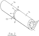
- Fig. 2 presents one embodiment of the invention wherein the rotor having a laminate structure consists of two subrotors 14 that are disposed axially one after the other.
- the subrotors are mechanically and fixedly joined together to form a jointly operating assembly, while having a radial gap 15 therebetween.
- the gap 15 extends to the outer surface of the rotor from the air channel systems 7 that run axially inside the rotor from one end to the other.
- the subrotors 14 may even be fixedly mounted to each other in the rotor inward from the air channel systems 7.
- the air channel systems 7 act as air supply channels for the radial gap or gaps 15 that effectively supply in the radial direction the air flow that flows axially through the rotor to the stator as the cooling air it needs.
- the cooling flow is provided in this structure effectively and even in the correct order because the rotor that is more critical in terms of excessive heating is cooled first, and the stator is cooled thereafter by the same air flow.
- the radial gap and any possible blades or corresponding members therein constitute an effective centrifugal blower by which the cooling of the rotor and the stator is carried out effectively.
Landscapes
- Engineering & Computer Science (AREA)
- Power Engineering (AREA)
- Permanent Field Magnets Of Synchronous Machinery (AREA)
- Iron Core Of Rotating Electric Machines (AREA)
Description
- The invention relates to a laminated rotor structure of a rotor for a permanent magnet synchronous machine as defined in the preamble of
claim 1. - In permanent magnet synchronous machines it is common to use laminated rotor structures, i.e. disk rotors, wherein the actual body of the rotor around the shaft is made from a large number of round and thin ferromagnetic metal disks that are identical in shape, disposed perpendicularly relative to the shaft and packed into a tight assembly. The permanent magnets are then provided to the body of the rotor, either to the surface or embedded deeper as rods extending from one end of the cylindrical rotor to the other.
- In the invention, the permanent magnets are disposed inside the rotor body in a ring-type V-shape configuration known per se, i.e. the first ends of the permanent magnets are close to the surface of the rotor and the second ends are closer to the central axis but disposed at an angle to the radial direction. This way, every second magnet is inclined in one direction and every second in the other direction relative to the radial direction. This type of structure has been disclosed in publication
JP 2006050821 - Another structure representing the prior art has been disclosed in patent
US 4445062 . It features permanent magnet rods embedded in the rotor, in radial grooves on the surface thereof, in such a way that the poles of the permanent magnets are disposed one after the other in the circumferential direction. The bottom of a groove is so dimensioned or shaped relative to the permanent magnet as to form on the bottom of the groove a gap that can act as a cooling air channel that extends axially through the rotor. The purpose of the structure is simply and securely to fix the magnets in place in the rotor. The publication does not discuss minimization of the leakage flux of the magnets. - One more structure is disclosed in patent application
US 2010/0133941 . It features line-start permanent-magnet rotors, where the permanent-magnet rotors have permanent-magnet bulks in W-like shapes, vent openings between bulks, and/or air gaps at ends of PM bulks in the W-like shapes. - The ferromagnetic disk pack constitutes a good body for the rotor around the magnets, but heating of the rotor and particularly of the magnets causes problems specifically in large machines. Another problem is the leakage flux of the rotor and the armature reaction, i.e. the magnetic flux tends to move sideways on the rotor pole, which is not a desirable phenomenon.
- Publication
WO2010047657 describes an electric motor that comprises a stator and a rotor of hybrid type. The rotor comprises a rotor core comprising an annular radially outer section of asynchronous type and an annular radially inner section of synchronous type arranged radially inside said outer section. - Publication
JP2009195088 - Publication
US4445062 describes a rotor assembly that comprises wedge-shaped permanent magnets and anchors with undulating sides for attaching a rotor hub to pole bodies. - Publication
JP2010193660 - The objective of the invention is to remedy the defects of the prior art referred to above. In particular, the objective of the invention is to disclose a novel laminate rotor structure wherein the excessive heating of the magnets has been prevented and wherein the magnetic fluxes are made to move in an optimal fashion, minimizing the leakage fluxes.
- In accordance with the invention, there is provided a new laminated rotor structure of a rotor for a permanent magnet synchronous machine. The laminated rotor structure of the rotor is defined in an accompanying independent claim.
- The laminated rotor structure of the rotor according to the invention provides considerable advantages as compared to the prior art. The temperature of the rotor and, most importantly, of the magnets therein can be kept within allowable limits to maintain their magnetic properties. Further, the magnetic flux is made to move in the rotor structure in an optimal fashion by virtue of properly placed flux blocks, minimizing leakage fluxes of the permanent magnets, which has a considerable effect on the size of the electric machine. In addition, the rotor is made mechanically robust by virtue of the inventive structure.
- A laminated rotor structure of a rotor according to an exemplifying embodiment is defined in an accompanying dependent claim.
- In the following, the invention will be described in detail with reference to the accompanying drawings, in which
-
Fig. 1 presents a sectional view of a sector of the structure of a rotor according to the invention and -
Fig. 2 schematically presents air circulation of the rotor. -
Fig. 1 presents the structure of a rotor that has been laminated from ferromagnetic disks in a permanent magnet synchronous machine. More specifically, a sectional view of a sector delimited by dash lines, including one V-shaped pair of permanent magnets. There are a number of these kinds of sectors present in the rotor, for example at least eight or even much more. - The rotor thus consists of a large number of ferromagnetic round disks tightly disposed side by side as a single pack in the axial direction of the rotor. The structures included in the sector extend axially, identically and unchangeably, through the entire disk pack structure of the rotor. In proximity to the
surface 2 of adisk 1 inside the rotor there are a number of generally copper-madebars 3 of a damper winding, connected in a manner known per se to copper short-circuiting rings disposed at each end of the rotor. Twopermanent magnets 4 are disposed at an angle α to each other so that thefirst ends 5 of the magnets are disposed at a distance from each other close to theouter surface 2 of the rotor and thesecond ends 6 are disposed closer to the shaft of the rotor adjacent to each other but not entirely engaged to each other. - The angle α between the
magnets 4 that opens outward encompasses a support structure formed by twonon-ferromagnetic support bolts 11 mounted in the radial direction on the bisector of the angle α and by anair gap 12 to connect them, having a width that is smaller than the diameter of the bolts. The support bolts and the air gap together constitute a non-ferromagnetic structure that directs the magnetic flux in the area of the angle α to the radial direction of the rotor. - Provided from the
second end 6 of themagnets 4 toward the shaft of the rotor there is anair channel system 7 that extends from one end of the rotor to the other. Theair channel system 7 is formed by twosubchannels 9, and between the subchannels there is a radial neck 8 disposed in the direction of the bisector of the angle α that is made of the same monolithic material as thedisk 1. Thesubchannels 9 are so shaped as to be in direct heat transfer communication to thesecond end 6 of therespective magnet 4 over aspecific segment 13 of the end of the magnet. Thus, the magnets stay tightly and precisely in place, while being at the same time efficiently cooled by virtue of the air flow that directly flushes their surface. - The purpose of the neck 8 made from the material of the
disk 1 is effectively to direct the magnetic flux around thesubchannels 9 in order to minimize the leakage flux. Another purpose of the neck 8 is mechanically to support the rotor structure in the radial direction, as the strong centrifugal forces that act on themagnets 4 and thebars 3 could damage the rotor without the neck 8 giving support to the structure. -
Fig. 2 presents one embodiment of the invention wherein the rotor having a laminate structure consists of twosubrotors 14 that are disposed axially one after the other. The subrotors are mechanically and fixedly joined together to form a jointly operating assembly, while having aradial gap 15 therebetween. Thegap 15 extends to the outer surface of the rotor from theair channel systems 7 that run axially inside the rotor from one end to the other. Thesubrotors 14 may even be fixedly mounted to each other in the rotor inward from theair channel systems 7. Thus, theair channel systems 7 act as air supply channels for the radial gap orgaps 15 that effectively supply in the radial direction the air flow that flows axially through the rotor to the stator as the cooling air it needs. The cooling flow is provided in this structure effectively and even in the correct order because the rotor that is more critical in terms of excessive heating is cooled first, and the stator is cooled thereafter by the same air flow. The radial gap and any possible blades or corresponding members therein constitute an effective centrifugal blower by which the cooling of the rotor and the stator is carried out effectively. - The invention is not limited merely to the examples referred to above; instead, many variations are possible within the scope of the inventive idea defined by the claims.
Claims (2)
- A laminated rotor structure of a rotor for a permanent magnet synchronous machine, the laminated rotor structure comprising disks (1) of ferromagnetic material constituting a body of the rotor that includes bars (3) of a damper winding extending axially close to an outer surface (2) of the rotor from one end of the body of the rotor to another end of the body of the rotor, and a circle of permanent magnets (4) arranged to constitute pairs of permanent magnets so that the permanent magnets of each pair of permanent magnets are disposed in a V-shaped configuration forming a V-shaped area close to an outer perimeter of the rotor and between the two magnets of each pair of permanent magnets inside a circle formed by the bars, wherein first ends (5) of the permanent magnets of each pair of permanent magnets are disposed close to the outer perimeter of the rotor and second ends (6) of the permanent magnets of each pair of permanent magnets are disposed closer to a central axis of the rotor than the first ends of the the permanent magnets, and wherein the permanent magnets of each pair of permanent magnets are disposed at an angle (α) to each other so that their first ends (5) are disposed at a distance from each other and their second ends (6) in proximity to each other, and that each pair of permanent magnets includes an air channel system (7) that extends axially through the laminated rotor structure of the rotor and is in a direct heat transfer contact with the second ends (6) of the permanent magnets of the pair of permanent magnets, wherein each V-shaped area includes a non-ferromagnetic support structure (10) that extends axially through the rotor, characterized in that the support structure (10) includes two non-ferromagnetic support bolts (11) disposed at a distance from each other in a radial direction of the rotor and an air gap (12) provided in the radial direction of the rotor to connect them, wherein each air channel system (7) is symmetrical relative to a bisector of the angle (α) in the radial direction of the rotor and each air channel system (7) includes a ferromagnetic neck (8) disposed in the direction of the bisector of the angle, dividing the air channel system under consideration in two subchannels (9) that are symmetrical relative to the neck.
- The laminated rotor structure of a rotor according to claim 1, characterized in that each support structure (10) is formed by a structure disposed on a bisector of the angle (α) in the radial direction of the rotor.
Applications Claiming Priority (3)
| Application Number | Priority Date | Filing Date | Title |
|---|---|---|---|
| FI20115076A FI20115076A0 (en) | 2011-01-26 | 2011-01-26 | Laminated rotor construction in a permanent magnet synchronous machine |
| PCT/FI2012/050065 WO2012101328A1 (en) | 2011-01-26 | 2012-01-25 | Laminated rotor structure for a permanent magnet synchronous machine |
| EP12739830.3A EP2668711A4 (en) | 2011-01-26 | 2012-01-25 | Laminated rotor structure for a permanent magnet synchronous machine |
Related Parent Applications (1)
| Application Number | Title | Priority Date | Filing Date |
|---|---|---|---|
| EP12739830.3A Division EP2668711A4 (en) | 2011-01-26 | 2012-01-25 | Laminated rotor structure for a permanent magnet synchronous machine |
Publications (2)
| Publication Number | Publication Date |
|---|---|
| EP3661022A1 EP3661022A1 (en) | 2020-06-03 |
| EP3661022B1 true EP3661022B1 (en) | 2022-01-05 |
Family
ID=43528562
Family Applications (2)
| Application Number | Title | Priority Date | Filing Date |
|---|---|---|---|
| EP12739830.3A Ceased EP2668711A4 (en) | 2011-01-26 | 2012-01-25 | Laminated rotor structure for a permanent magnet synchronous machine |
| EP20152437.8A Active EP3661022B1 (en) | 2011-01-26 | 2012-01-25 | Laminated rotor structure for a permanent magnet synchronous machine |
Family Applications Before (1)
| Application Number | Title | Priority Date | Filing Date |
|---|---|---|---|
| EP12739830.3A Ceased EP2668711A4 (en) | 2011-01-26 | 2012-01-25 | Laminated rotor structure for a permanent magnet synchronous machine |
Country Status (4)
| Country | Link |
|---|---|
| US (1) | US9178399B2 (en) |
| EP (2) | EP2668711A4 (en) |
| FI (1) | FI20115076A0 (en) |
| WO (1) | WO2012101328A1 (en) |
Cited By (1)
| Publication number | Priority date | Publication date | Assignee | Title |
|---|---|---|---|---|
| WO2023194675A1 (en) * | 2022-04-07 | 2023-10-12 | Novares France | Rotor for an electric motor provided with a cooling circuit |
Families Citing this family (8)
| Publication number | Priority date | Publication date | Assignee | Title |
|---|---|---|---|---|
| JP5757281B2 (en) * | 2012-11-02 | 2015-07-29 | 株式会社デンソー | Rotating electrical machine rotor |
| CN103973005A (en) * | 2013-01-24 | 2014-08-06 | 艾默生环境优化技术(苏州)有限公司 | Rotor and motor and compressor comprising same |
| JP6169496B2 (en) * | 2014-01-09 | 2017-07-26 | 株式会社日立製作所 | Permanent magnet rotating electric machine |
| US10491066B2 (en) * | 2015-06-16 | 2019-11-26 | Danfoss Editron Oy | Method and arrangement for adjusting the magnetization of a permanent magnet machine |
| US9755463B2 (en) | 2015-08-11 | 2017-09-05 | Genesis Robotics Llp | Electric machine |
| US11139707B2 (en) | 2015-08-11 | 2021-10-05 | Genesis Robotics And Motion Technologies Canada, Ulc | Axial gap electric machine with permanent magnets arranged between posts |
| US11043885B2 (en) | 2016-07-15 | 2021-06-22 | Genesis Robotics And Motion Technologies Canada, Ulc | Rotary actuator |
| US12107465B2 (en) * | 2020-09-07 | 2024-10-01 | ElectromagnetiX LLC | Motor using permanent magnets and induction windings for use with an electrical submersible pump |
Family Cites Families (19)
| Publication number | Priority date | Publication date | Assignee | Title |
|---|---|---|---|---|
| US4445062A (en) | 1978-12-26 | 1984-04-24 | The Garrett Corporation | Rotor assembly having anchors with undulating sides |
| DE4033454A1 (en) * | 1990-10-20 | 1992-04-23 | Bosch Gmbh Robert | Slotted permanent-magnet rotor esp. for synchronous motor - is formed with magnets injected into slots arranged at uniform angular spacing around circumference of body |
| JP2000139063A (en) | 1998-11-02 | 2000-05-16 | Meidensha Corp | Permanent magnet type synchronous rotating electric machine |
| JP2000287395A (en) * | 1999-03-30 | 2000-10-13 | Toshiba Corp | Rotor of permanent magnet type reluctance type rotating electric machine |
| US6727627B1 (en) * | 1999-07-16 | 2004-04-27 | Matsushita Electric Industrial Co., Ltd. | Permanent magnet synchronous motor |
| JP4358703B2 (en) | 2004-08-05 | 2009-11-04 | アスモ株式会社 | Embedded magnet type motor |
| US20090256435A1 (en) | 2005-08-25 | 2009-10-15 | Power Group International, Inc. | Device and Method to Clamp and Lock Permanent Magnets and Improve Cooling within a Rotating Electrical Machine |
| JP4660406B2 (en) | 2005-09-07 | 2011-03-30 | 株式会社東芝 | Rotating electric machine |
| US7772736B2 (en) * | 2006-06-09 | 2010-08-10 | Hitachi Appliances, Inc. | Permanent magnet synchronous motor, rotor of the same, and compressor using the same |
| BRPI0603363B1 (en) * | 2006-08-16 | 2018-03-13 | Whirlpool S.A. | "SYNCHRONARY MACHINE" |
| US7923881B2 (en) * | 2007-05-04 | 2011-04-12 | A.O. Smith Corporation | Interior permanent magnet motor and rotor |
| JP4757238B2 (en) | 2007-07-13 | 2011-08-24 | アイシン・エィ・ダブリュ株式会社 | Cooling structure and cooling method for rotating electrical machine |
| JP4528825B2 (en) * | 2007-12-21 | 2010-08-25 | 日立アプライアンス株式会社 | Self-starting permanent magnet synchronous motor and compressor using the same |
| JP2009195088A (en) * | 2008-02-18 | 2009-08-27 | Toyota Industries Corp | Rotating electric machine and manufacturing method thereof |
| KR101067550B1 (en) * | 2008-07-16 | 2011-09-27 | 엘지전자 주식회사 | Air conditioning system and its control method |
| SE534248C2 (en) * | 2008-10-23 | 2011-06-14 | Itt Mfg Enterprises Inc | Rotor agitator assembly comprising sections of synchronous and asynchronous type |
| CN201294443Y (en) * | 2008-12-01 | 2009-08-19 | 东元总合科技(杭州)有限公司 | Permanent magnet self-startup synchronous motor rotor |
| JP5387033B2 (en) * | 2009-02-19 | 2014-01-15 | 新日鐵住金株式会社 | Split rotor and electric motor |
| CN101867272A (en) * | 2010-06-30 | 2010-10-20 | 无锡哈电电机有限公司 | Rotor iron core of two-cage three-phase asynchronous motor |
-
2011
- 2011-01-26 FI FI20115076A patent/FI20115076A0/en not_active Application Discontinuation
-
2012
- 2012-01-25 WO PCT/FI2012/050065 patent/WO2012101328A1/en not_active Ceased
- 2012-01-25 US US13/981,749 patent/US9178399B2/en active Active
- 2012-01-25 EP EP12739830.3A patent/EP2668711A4/en not_active Ceased
- 2012-01-25 EP EP20152437.8A patent/EP3661022B1/en active Active
Non-Patent Citations (1)
| Title |
|---|
| None * |
Cited By (2)
| Publication number | Priority date | Publication date | Assignee | Title |
|---|---|---|---|---|
| WO2023194675A1 (en) * | 2022-04-07 | 2023-10-12 | Novares France | Rotor for an electric motor provided with a cooling circuit |
| FR3134486A1 (en) * | 2022-04-07 | 2023-10-13 | Novares France | ROTOR FOR ELECTRIC MOTOR PROVIDED WITH A COOLING CIRCUIT |
Also Published As
| Publication number | Publication date |
|---|---|
| EP3661022A1 (en) | 2020-06-03 |
| EP2668711A4 (en) | 2018-07-04 |
| WO2012101328A1 (en) | 2012-08-02 |
| FI20115076A0 (en) | 2011-01-26 |
| EP2668711A1 (en) | 2013-12-04 |
| US9178399B2 (en) | 2015-11-03 |
| US20130307358A1 (en) | 2013-11-21 |
Similar Documents
| Publication | Publication Date | Title |
|---|---|---|
| EP3661022A1 (en) | Laminated rotor structure for a permanent magnet synchronous machine | |
| EP2961043B1 (en) | Rotor of rotary electric machine | |
| EP2973949B1 (en) | Rotor for rotary electric machine and rotary electric machine | |
| US6229238B1 (en) | Transversal flux machine | |
| EP2622716B1 (en) | Magnetic rotor having inset bridges to promote cooling | |
| US10069357B2 (en) | Spoke permanent magnet rotor | |
| US20150028710A1 (en) | Rotor for rotating electric machine, rotating electric machine, and method for manufacturing rotor for rotating electric machine | |
| EP3022829B1 (en) | A rotor for an electric motor | |
| US20210091610A1 (en) | Stator tooth arrangement | |
| US10158265B2 (en) | Embedded permanent magnet type rotating electric machine | |
| CN116918227A (en) | Stator of axial flux motor | |
| US20130249342A1 (en) | Cantilevered Rotor Magnet Support | |
| JP2017046545A (en) | Rotary electric machine rotor | |
| US11545860B2 (en) | Inserts for motor rotor core | |
| US11296577B2 (en) | Electric drive motor | |
| CN106068599A (en) | Rotary motor rotor | |
| US9866082B2 (en) | Rotor and a motor and compressor comprising the rotor | |
| JP2012019623A (en) | Rotor core | |
| EP3648310A1 (en) | Rotor and ipm motor using same | |
| CN114287098A (en) | Laminated rotor core for rotor and method for manufacturing laminated rotor core | |
| CN102624176A (en) | High-power-density high-power disc type driving motor | |
| EP2477313B1 (en) | An electric machine | |
| EP1966870B1 (en) | An electric motor | |
| CN105990920A (en) | Rotor iron core and motor having the same | |
| US20200052536A1 (en) | Hybrid module including rotor having coolant flow channels |
Legal Events
| Date | Code | Title | Description |
|---|---|---|---|
| PUAI | Public reference made under article 153(3) epc to a published international application that has entered the european phase |
Free format text: ORIGINAL CODE: 0009012 |
|
| STAA | Information on the status of an ep patent application or granted ep patent |
Free format text: STATUS: THE APPLICATION HAS BEEN PUBLISHED |
|
| STAA | Information on the status of an ep patent application or granted ep patent |
Free format text: STATUS: REQUEST FOR EXAMINATION WAS MADE |
|
| AC | Divisional application: reference to earlier application |
Ref document number: 2668711 Country of ref document: EP Kind code of ref document: P |
|
| AK | Designated contracting states |
Kind code of ref document: A1 Designated state(s): AL AT BE BG CH CY CZ DE DK EE ES FI FR GB GR HR HU IE IS IT LI LT LU LV MC MK MT NL NO PL PT RO RS SE SI SK SM TR |
|
| 17P | Request for examination filed |
Effective date: 20200512 |
|
| RBV | Designated contracting states (corrected) |
Designated state(s): AL AT BE BG CH CY CZ DE DK EE ES FI FR GB GR HR HU IE IS IT LI LT LU LV MC MK MT NL NO PL PT RO RS SE SI SK SM TR |
|
| STAA | Information on the status of an ep patent application or granted ep patent |
Free format text: STATUS: EXAMINATION IS IN PROGRESS |
|
| 17Q | First examination report despatched |
Effective date: 20200715 |
|
| GRAP | Despatch of communication of intention to grant a patent |
Free format text: ORIGINAL CODE: EPIDOSNIGR1 |
|
| STAA | Information on the status of an ep patent application or granted ep patent |
Free format text: STATUS: GRANT OF PATENT IS INTENDED |
|
| INTG | Intention to grant announced |
Effective date: 20210924 |
|
| GRAS | Grant fee paid |
Free format text: ORIGINAL CODE: EPIDOSNIGR3 |
|
| GRAA | (expected) grant |
Free format text: ORIGINAL CODE: 0009210 |
|
| STAA | Information on the status of an ep patent application or granted ep patent |
Free format text: STATUS: THE PATENT HAS BEEN GRANTED |
|
| AC | Divisional application: reference to earlier application |
Ref document number: 2668711 Country of ref document: EP Kind code of ref document: P |
|
| AK | Designated contracting states |
Kind code of ref document: B1 Designated state(s): AL AT BE BG CH CY CZ DE DK EE ES FI FR GB GR HR HU IE IS IT LI LT LU LV MC MK MT NL NO PL PT RO RS SE SI SK SM TR |
|
| REG | Reference to a national code |
Ref country code: GB Ref legal event code: FG4D |
|
| REG | Reference to a national code |
Ref country code: CH Ref legal event code: EP |
|
| REG | Reference to a national code |
Ref country code: AT Ref legal event code: REF Ref document number: 1461461 Country of ref document: AT Kind code of ref document: T Effective date: 20220115 |
|
| REG | Reference to a national code |
Ref country code: DE Ref legal event code: R096 Ref document number: 602012077515 Country of ref document: DE |
|
| REG | Reference to a national code |
Ref country code: IE Ref legal event code: FG4D |
|
| REG | Reference to a national code |
Ref country code: SE Ref legal event code: TRGR |
|
| REG | Reference to a national code |
Ref country code: FI Ref legal event code: FGE |
|
| REG | Reference to a national code |
Ref country code: NO Ref legal event code: T2 Effective date: 20220105 |
|
| REG | Reference to a national code |
Ref country code: LT Ref legal event code: MG9D |
|
| REG | Reference to a national code |
Ref country code: NL Ref legal event code: MP Effective date: 20220105 |
|
| REG | Reference to a national code |
Ref country code: AT Ref legal event code: MK05 Ref document number: 1461461 Country of ref document: AT Kind code of ref document: T Effective date: 20220105 |
|
| PG25 | Lapsed in a contracting state [announced via postgrant information from national office to epo] |
Ref country code: NL Free format text: LAPSE BECAUSE OF FAILURE TO SUBMIT A TRANSLATION OF THE DESCRIPTION OR TO PAY THE FEE WITHIN THE PRESCRIBED TIME-LIMIT Effective date: 20220105 |
|
| PG25 | Lapsed in a contracting state [announced via postgrant information from national office to epo] |
Ref country code: RS Free format text: LAPSE BECAUSE OF FAILURE TO SUBMIT A TRANSLATION OF THE DESCRIPTION OR TO PAY THE FEE WITHIN THE PRESCRIBED TIME-LIMIT Effective date: 20220105 Ref country code: PT Free format text: LAPSE BECAUSE OF FAILURE TO SUBMIT A TRANSLATION OF THE DESCRIPTION OR TO PAY THE FEE WITHIN THE PRESCRIBED TIME-LIMIT Effective date: 20220505 Ref country code: LT Free format text: LAPSE BECAUSE OF FAILURE TO SUBMIT A TRANSLATION OF THE DESCRIPTION OR TO PAY THE FEE WITHIN THE PRESCRIBED TIME-LIMIT Effective date: 20220105 Ref country code: HR Free format text: LAPSE BECAUSE OF FAILURE TO SUBMIT A TRANSLATION OF THE DESCRIPTION OR TO PAY THE FEE WITHIN THE PRESCRIBED TIME-LIMIT Effective date: 20220105 Ref country code: ES Free format text: LAPSE BECAUSE OF FAILURE TO SUBMIT A TRANSLATION OF THE DESCRIPTION OR TO PAY THE FEE WITHIN THE PRESCRIBED TIME-LIMIT Effective date: 20220105 Ref country code: BG Free format text: LAPSE BECAUSE OF FAILURE TO SUBMIT A TRANSLATION OF THE DESCRIPTION OR TO PAY THE FEE WITHIN THE PRESCRIBED TIME-LIMIT Effective date: 20220405 |
|
| PG25 | Lapsed in a contracting state [announced via postgrant information from national office to epo] |
Ref country code: PL Free format text: LAPSE BECAUSE OF FAILURE TO SUBMIT A TRANSLATION OF THE DESCRIPTION OR TO PAY THE FEE WITHIN THE PRESCRIBED TIME-LIMIT Effective date: 20220105 Ref country code: LV Free format text: LAPSE BECAUSE OF FAILURE TO SUBMIT A TRANSLATION OF THE DESCRIPTION OR TO PAY THE FEE WITHIN THE PRESCRIBED TIME-LIMIT Effective date: 20220105 Ref country code: GR Free format text: LAPSE BECAUSE OF FAILURE TO SUBMIT A TRANSLATION OF THE DESCRIPTION OR TO PAY THE FEE WITHIN THE PRESCRIBED TIME-LIMIT Effective date: 20220406 Ref country code: AT Free format text: LAPSE BECAUSE OF FAILURE TO SUBMIT A TRANSLATION OF THE DESCRIPTION OR TO PAY THE FEE WITHIN THE PRESCRIBED TIME-LIMIT Effective date: 20220105 |
|
| REG | Reference to a national code |
Ref country code: CH Ref legal event code: PL |
|
| PG25 | Lapsed in a contracting state [announced via postgrant information from national office to epo] |
Ref country code: IS Free format text: LAPSE BECAUSE OF FAILURE TO SUBMIT A TRANSLATION OF THE DESCRIPTION OR TO PAY THE FEE WITHIN THE PRESCRIBED TIME-LIMIT Effective date: 20220505 |
|
| REG | Reference to a national code |
Ref country code: BE Ref legal event code: MM Effective date: 20220131 |
|
| REG | Reference to a national code |
Ref country code: DE Ref legal event code: R097 Ref document number: 602012077515 Country of ref document: DE |
|
| PG25 | Lapsed in a contracting state [announced via postgrant information from national office to epo] |
Ref country code: SM Free format text: LAPSE BECAUSE OF FAILURE TO SUBMIT A TRANSLATION OF THE DESCRIPTION OR TO PAY THE FEE WITHIN THE PRESCRIBED TIME-LIMIT Effective date: 20220105 Ref country code: SK Free format text: LAPSE BECAUSE OF FAILURE TO SUBMIT A TRANSLATION OF THE DESCRIPTION OR TO PAY THE FEE WITHIN THE PRESCRIBED TIME-LIMIT Effective date: 20220105 Ref country code: RO Free format text: LAPSE BECAUSE OF FAILURE TO SUBMIT A TRANSLATION OF THE DESCRIPTION OR TO PAY THE FEE WITHIN THE PRESCRIBED TIME-LIMIT Effective date: 20220105 Ref country code: MC Free format text: LAPSE BECAUSE OF FAILURE TO SUBMIT A TRANSLATION OF THE DESCRIPTION OR TO PAY THE FEE WITHIN THE PRESCRIBED TIME-LIMIT Effective date: 20220105 Ref country code: LU Free format text: LAPSE BECAUSE OF NON-PAYMENT OF DUE FEES Effective date: 20220125 Ref country code: EE Free format text: LAPSE BECAUSE OF FAILURE TO SUBMIT A TRANSLATION OF THE DESCRIPTION OR TO PAY THE FEE WITHIN THE PRESCRIBED TIME-LIMIT Effective date: 20220105 Ref country code: DK Free format text: LAPSE BECAUSE OF FAILURE TO SUBMIT A TRANSLATION OF THE DESCRIPTION OR TO PAY THE FEE WITHIN THE PRESCRIBED TIME-LIMIT Effective date: 20220105 Ref country code: CZ Free format text: LAPSE BECAUSE OF FAILURE TO SUBMIT A TRANSLATION OF THE DESCRIPTION OR TO PAY THE FEE WITHIN THE PRESCRIBED TIME-LIMIT Effective date: 20220105 |
|
| PLBE | No opposition filed within time limit |
Free format text: ORIGINAL CODE: 0009261 |
|
| STAA | Information on the status of an ep patent application or granted ep patent |
Free format text: STATUS: NO OPPOSITION FILED WITHIN TIME LIMIT |
|
| PG25 | Lapsed in a contracting state [announced via postgrant information from national office to epo] |
Ref country code: BE Free format text: LAPSE BECAUSE OF NON-PAYMENT OF DUE FEES Effective date: 20220131 Ref country code: AL Free format text: LAPSE BECAUSE OF FAILURE TO SUBMIT A TRANSLATION OF THE DESCRIPTION OR TO PAY THE FEE WITHIN THE PRESCRIBED TIME-LIMIT Effective date: 20220105 |
|
| 26N | No opposition filed |
Effective date: 20221006 |
|
| PG25 | Lapsed in a contracting state [announced via postgrant information from national office to epo] |
Ref country code: LI Free format text: LAPSE BECAUSE OF NON-PAYMENT OF DUE FEES Effective date: 20220131 Ref country code: CH Free format text: LAPSE BECAUSE OF NON-PAYMENT OF DUE FEES Effective date: 20220131 |
|
| PG25 | Lapsed in a contracting state [announced via postgrant information from national office to epo] |
Ref country code: IE Free format text: LAPSE BECAUSE OF NON-PAYMENT OF DUE FEES Effective date: 20220125 |
|
| PG25 | Lapsed in a contracting state [announced via postgrant information from national office to epo] |
Ref country code: SI Free format text: LAPSE BECAUSE OF FAILURE TO SUBMIT A TRANSLATION OF THE DESCRIPTION OR TO PAY THE FEE WITHIN THE PRESCRIBED TIME-LIMIT Effective date: 20220105 |
|
| P01 | Opt-out of the competence of the unified patent court (upc) registered |
Effective date: 20230617 |
|
| REG | Reference to a national code |
Ref country code: NO Ref legal event code: CREP Ref country code: NO Ref legal event code: CHAD Owner name: DANFOSS A/S, DK |
|
| REG | Reference to a national code |
Ref country code: FI Ref legal event code: PCE Owner name: DANFOSS A/S |
|
| REG | Reference to a national code |
Ref country code: GB Ref legal event code: 732E Free format text: REGISTERED BETWEEN 20240229 AND 20240306 |
|
| PG25 | Lapsed in a contracting state [announced via postgrant information from national office to epo] |
Ref country code: MK Free format text: LAPSE BECAUSE OF FAILURE TO SUBMIT A TRANSLATION OF THE DESCRIPTION OR TO PAY THE FEE WITHIN THE PRESCRIBED TIME-LIMIT Effective date: 20220105 Ref country code: CY Free format text: LAPSE BECAUSE OF FAILURE TO SUBMIT A TRANSLATION OF THE DESCRIPTION OR TO PAY THE FEE WITHIN THE PRESCRIBED TIME-LIMIT Effective date: 20220105 |
|
| PG25 | Lapsed in a contracting state [announced via postgrant information from national office to epo] |
Ref country code: HU Free format text: LAPSE BECAUSE OF FAILURE TO SUBMIT A TRANSLATION OF THE DESCRIPTION OR TO PAY THE FEE WITHIN THE PRESCRIBED TIME-LIMIT; INVALID AB INITIO Effective date: 20120125 |
|
| PG25 | Lapsed in a contracting state [announced via postgrant information from national office to epo] |
Ref country code: TR Free format text: LAPSE BECAUSE OF FAILURE TO SUBMIT A TRANSLATION OF THE DESCRIPTION OR TO PAY THE FEE WITHIN THE PRESCRIBED TIME-LIMIT Effective date: 20220105 |
|
| PG25 | Lapsed in a contracting state [announced via postgrant information from national office to epo] |
Ref country code: MT Free format text: LAPSE BECAUSE OF FAILURE TO SUBMIT A TRANSLATION OF THE DESCRIPTION OR TO PAY THE FEE WITHIN THE PRESCRIBED TIME-LIMIT Effective date: 20220105 |
|
| REG | Reference to a national code |
Ref country code: DE Ref legal event code: R081 Ref document number: 602012077515 Country of ref document: DE Owner name: DANFOSS A/S, DK Free format text: FORMER OWNER: DANFOSS EDITRON OY, LAPPEENRANTA, FI |
|
| PGFP | Annual fee paid to national office [announced via postgrant information from national office to epo] |
Ref country code: GB Payment date: 20251219 Year of fee payment: 15 |
|
| PGFP | Annual fee paid to national office [announced via postgrant information from national office to epo] |
Ref country code: FI Payment date: 20251230 Year of fee payment: 15 |
|
| PGFP | Annual fee paid to national office [announced via postgrant information from national office to epo] |
Ref country code: FR Payment date: 20251222 Year of fee payment: 15 |
|
| PGFP | Annual fee paid to national office [announced via postgrant information from national office to epo] |
Ref country code: SE Payment date: 20251210 Year of fee payment: 15 |
|
| PGFP | Annual fee paid to national office [announced via postgrant information from national office to epo] |
Ref country code: NO Payment date: 20260109 Year of fee payment: 15 Ref country code: DE Payment date: 20251203 Year of fee payment: 15 |
|
| PGFP | Annual fee paid to national office [announced via postgrant information from national office to epo] |
Ref country code: IT Payment date: 20251219 Year of fee payment: 15 |