EP3661002B1 - Method for controlling battery power limit value - Google Patents
Method for controlling battery power limit value Download PDFInfo
- Publication number
- EP3661002B1 EP3661002B1 EP18879208.9A EP18879208A EP3661002B1 EP 3661002 B1 EP3661002 B1 EP 3661002B1 EP 18879208 A EP18879208 A EP 18879208A EP 3661002 B1 EP3661002 B1 EP 3661002B1
- Authority
- EP
- European Patent Office
- Prior art keywords
- power limit
- battery
- voltage
- time
- predetermined
- Prior art date
- Legal status (The legal status is an assumption and is not a legal conclusion. Google has not performed a legal analysis and makes no representation as to the accuracy of the status listed.)
- Active
Links
- 238000000034 method Methods 0.000 title claims description 31
- 238000007599 discharging Methods 0.000 claims description 89
- 230000007423 decrease Effects 0.000 claims description 6
- 238000007796 conventional method Methods 0.000 description 1
- 230000000694 effects Effects 0.000 description 1
- 238000005516 engineering process Methods 0.000 description 1
- 238000012986 modification Methods 0.000 description 1
- 230000004048 modification Effects 0.000 description 1
- 238000012544 monitoring process Methods 0.000 description 1
Images


Classifications
-
- H—ELECTRICITY
- H02—GENERATION; CONVERSION OR DISTRIBUTION OF ELECTRIC POWER
- H02J—CIRCUIT ARRANGEMENTS OR SYSTEMS FOR SUPPLYING OR DISTRIBUTING ELECTRIC POWER; SYSTEMS FOR STORING ELECTRIC ENERGY
- H02J7/00—Circuit arrangements for charging or depolarising batteries or for supplying loads from batteries
- H02J7/007—Regulation of charging or discharging current or voltage
- H02J7/00712—Regulation of charging or discharging current or voltage the cycle being controlled or terminated in response to electric parameters
- H02J7/007182—Regulation of charging or discharging current or voltage the cycle being controlled or terminated in response to electric parameters in response to battery voltage
-
- H—ELECTRICITY
- H02—GENERATION; CONVERSION OR DISTRIBUTION OF ELECTRIC POWER
- H02J—CIRCUIT ARRANGEMENTS OR SYSTEMS FOR SUPPLYING OR DISTRIBUTING ELECTRIC POWER; SYSTEMS FOR STORING ELECTRIC ENERGY
- H02J7/00—Circuit arrangements for charging or depolarising batteries or for supplying loads from batteries
- H02J7/0013—Circuit arrangements for charging or depolarising batteries or for supplying loads from batteries acting upon several batteries simultaneously or sequentially
-
- G—PHYSICS
- G01—MEASURING; TESTING
- G01R—MEASURING ELECTRIC VARIABLES; MEASURING MAGNETIC VARIABLES
- G01R31/00—Arrangements for testing electric properties; Arrangements for locating electric faults; Arrangements for electrical testing characterised by what is being tested not provided for elsewhere
- G01R31/36—Arrangements for testing, measuring or monitoring the electrical condition of accumulators or electric batteries, e.g. capacity or state of charge [SoC]
- G01R31/3644—Constructional arrangements
- G01R31/3648—Constructional arrangements comprising digital calculation means, e.g. for performing an algorithm
-
- H—ELECTRICITY
- H01—ELECTRIC ELEMENTS
- H01M—PROCESSES OR MEANS, e.g. BATTERIES, FOR THE DIRECT CONVERSION OF CHEMICAL ENERGY INTO ELECTRICAL ENERGY
- H01M10/00—Secondary cells; Manufacture thereof
- H01M10/42—Methods or arrangements for servicing or maintenance of secondary cells or secondary half-cells
- H01M10/44—Methods for charging or discharging
-
- H—ELECTRICITY
- H02—GENERATION; CONVERSION OR DISTRIBUTION OF ELECTRIC POWER
- H02J—CIRCUIT ARRANGEMENTS OR SYSTEMS FOR SUPPLYING OR DISTRIBUTING ELECTRIC POWER; SYSTEMS FOR STORING ELECTRIC ENERGY
- H02J7/00—Circuit arrangements for charging or depolarising batteries or for supplying loads from batteries
- H02J7/0029—Circuit arrangements for charging or depolarising batteries or for supplying loads from batteries with safety or protection devices or circuits
- H02J7/00302—Overcharge protection
-
- Y—GENERAL TAGGING OF NEW TECHNOLOGICAL DEVELOPMENTS; GENERAL TAGGING OF CROSS-SECTIONAL TECHNOLOGIES SPANNING OVER SEVERAL SECTIONS OF THE IPC; TECHNICAL SUBJECTS COVERED BY FORMER USPC CROSS-REFERENCE ART COLLECTIONS [XRACs] AND DIGESTS
- Y02—TECHNOLOGIES OR APPLICATIONS FOR MITIGATION OR ADAPTATION AGAINST CLIMATE CHANGE
- Y02E—REDUCTION OF GREENHOUSE GAS [GHG] EMISSIONS, RELATED TO ENERGY GENERATION, TRANSMISSION OR DISTRIBUTION
- Y02E60/00—Enabling technologies; Technologies with a potential or indirect contribution to GHG emissions mitigation
- Y02E60/10—Energy storage using batteries
Definitions
- the present invention relates to a method for controlling a battery power limit.
- the present invention relates to a method for controlling a battery power limit on the basis of a current cell voltage.
- battery modules having at least one battery cell are electrically configured in series/parallel to each other, and a battery pack including at least one battery module has a rack battery management system (RBMS) for monitoring and controlling a state of the battery pack. Furthermore, each battery module has a module battery management system (MBMS) for controlling the battery module.
- RBMS rack battery management system
- MBMS module battery management system
- battery modules may be connected in series to output high power, or battery modules may be connected in parallel to increase an energy capacity or use time.
- a maximum output limit of the battery pack is set according to an SOC and temperature of the battery modules.
- Setting the maximum output limit of a battery pack by measuring a temperature of the battery pack is conventionally performed by setting the maximum output limit of the battery pack simply on the basis of a temperature or by setting the maximum output limit of the battery pack simply through a voltage of the battery pack.
- the maximum output value is calculated using a table including a temperature or battery pack voltage and a battery pack output limit.
- an additional table indicating a relationship between a temperature or voltage and a battery pack output limit should be stored.
- the present invention proposes a method in which only a maximum voltage and minimum voltage are checked in real time in battery modules connected in series or parallel and the maximum output limit of an entire battery pack is set on the basis of the maximum voltage and the minimum voltage without using the additional table including a temperature or voltage and a battery pack output limit.
- EP 3 046 211 A2 teaches reducing a charging current when a battery cell voltage reaches a high voltage threshold, wherein a counter value increases each time when the battery cell voltage reaches the high voltage threshold and when the counter value reaches a predetermined value, the charging ends. The amount of current reduction depends on the counter value.
- the present invention provided a method for setting a maximum output limit of a battery pack in real time.
- the present invention provided a method for setting a maximum output limit of a battery pack without an additional pre-stored table of a maximum output limit according to a temperature and SOC.
- a method for setting a charging power limit of a battery when charging the battery having a plurality of battery cells includes: a reference charging power limit setting step in which a referential predetermined charging power limit is set; a real-time charging power limit setting step in which a real-time charging power limit is calculated in real time according to a current voltage of the battery to set a real-time charging power limit of the battery; and a charging power limit restoring step in which the real-time charging power limit set in the real-time charging power limit setting step is restored to the referential predetermined charging power limit.
- the real-time charging power limit setting step includes: (a-1) a step of measuring a voltage of each of the plurality of battery cells; (b-1) a step of determining whether the voltage of a battery cell having a highest voltage among voltages of the plurality of battery cells measured in step (a-1) exceeds a preset maximum allowable voltage; (c-1) a step of measuring a period during which the voltage of the battery cell having the highest voltage exceeds the preset maximum allowable voltage; and (d-1) a step of setting the real-time charging power limit to a value obtained by reducing the referential battery charging power limit by a predetermined ratio when the period during which the voltage of the battery cell having the highest voltage exceeds the preset maximum allowable voltage is equal to or longer than a predetermined period in step (c-1), wherein steps (a-1) to (d-1) are repeatedly performed, and the number of times step (d-1) is performed is counted to generate a counted value.
- step (d-1) the predetermined ratio by which the referential battery charging power limit is reduced varies according to the counted value, wherein the counted value is limited to a predetermined value, and when the counted value reaches the predetermined value, charging of the battery is stopped.
- the counted value increases by 1 every time step (d-1) is performed once, and decreases by 1 when the battery which is in a charging state switches to a discharging state.
- the battery charging power limit may be restored to the referential predetermined charging power limit in any one case among: a case where the counted value is 0; a case where a current does not flow in the battery for at least a predetermined time; and a case where an SOC value of the battery reaches a predetermined reference SOC value.
- a method for setting a discharging power limit of a battery when discharging the battery having a plurality of battery cells includes: a reference discharging power limit setting step in which a referential predetermined discharging power limit is set; a real-time discharging power limit setting step in which a real-time discharging power limit is calculated in real time according to a current voltage of the battery to set a real-time discharging power limit of the battery; and a discharging power limit restoring step in which the real-time discharging power limit set in the real-time discharging power limit setting step is restored to the referential predetermined discharging power limit.
- the real-time discharging power limit setting step includes: (a-2) a step of measuring a voltage of each of the plurality of battery cells; (b-2) a step of determining whether the voltage of a battery cell having a lowest voltage among voltages of the plurality of battery cells measured in step (a-2) is less than a preset minimum allowable voltage; (c-2) a step of measuring a period during which the voltage of the battery cell having the lowest voltage is maintained less than the preset minimum allowable voltage; and (d-2) a step of reducing the referential predetermined battery discharging power limit by a predetermined ratio to calculate the real-time discharging power limit when the period during which the voltage of the battery cell having the lowest voltage is maintained less than the preset minimum allowable voltage is equal to or longer than a predetermined period, wherein steps (a-2) to (d-2) are repeatedly performed, and the number of times step (d-2) is performed is counted to generate a counted value.
- step (d-2) the predetermined ratio by which the referential battery charging power limit is reduced varies according to the counted value, wherein the counted value may be limited to a predetermined value, and when the counted value reaches the predetermined value, discharging of the battery may be stopped.
- the counted value increases by 1 every time step (d-2) is performed once, and decreases by 1 when the battery which is in a discharging state switches to a charging state.
- the battery discharging power limit may be restored to the referential predetermined discharging power limit in any one case among: a case where the counted value is 0; a case where a current does not flow in the battery for at least a predetermined time; and a case where an SOC value of the battery reaches a predetermined reference SOC value.
- a maximum output limit of a battery pack may be set in real time.
- a maximum output limit of a battery pack may be set without an additional pre-stored table of a maximum output limit according to a temperature and SOC.
- first, second or the like may be used for describing various elements but does not limit the elements. Such terms are only used for distinguishing one element from other elements. For example, without departing the scope of the present invention, a first element may be referred to as a second element, and likewise, a second element may be referred to as a first element.
- the terminology used herein is not for delimiting the present invention but for describing specific embodiments. The terms of a singular form may include plural forms unless otherwise specified.
- FIG. 1 is a flowchart illustrating the main steps of the method for setting a battery charging power limit at the time of charging according to an embodiment of the present invention.
- FIG. 2 is a detailed flowchart illustrating a real-time charging power limit setting step of the method for setting a battery charging power limit at the time of charging according to an embodiment of the present invention.
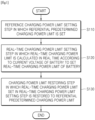
- the method for setting a battery power limit at the time of charging includes a reference charging power limit setting step in which a referential predetermined charging power limit is set (S 110), a real-time charging power limit setting step in which a real-time charging power limit is calculated in real time according to a current voltage of a battery to set a real-time charging power limit of the battery (S120), and a charging power limit restoring step in which the real-time charging power limit set in the real-time charging power limit setting step is restored to the referential predetermined charging power limit (S 130).
- the battery includes a plurality of battery cells
- the reference charging power limit setting step may be set to a predetermined value according to specifications of each of the plurality of battery cells included in the battery and entire battery specifications when designing the battery.
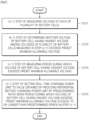
- the real-time charging power limit setting step (S 120) includes (a-1) a step of measuring a voltage of each of the plurality of battery cells (S121), (b-1) a step of determining whether the voltage of a battery cell having a highest voltage exceeds a preset maximum allowable voltage (S122), (c-1) a step of measuring a time during which the voltage of the battery cell having the highest voltage exceeds the preset maximum allowable voltage (S123), (d-1) a step of setting the real-time charging power limit to a value obtained by reducing the referential battery charging power limit by a predetermined ratio when a period during which the voltage of the battery cell having the highest voltage exceeds the preset maximum allowable voltage is equal to or longer than a predetermined period in step (c-1) (S124).
- steps (a-1) to (d-1) is repeatedly performed.
- the period during which the voltage of the battery cell having the highest voltage exceeds the preset maximum allowable voltage is measured from a point of time at which the voltage of the battery cell initially exceeds the preset maximum allowable voltage.
- Step (b-1) may be a step of determining whether the voltage of the battery cell having the highest voltage, among the plurality of battery cells, exceeds 4.2 V.
- step (c-1) when there is a battery cell having a voltage which exceeds 4.2 V in step (b-1), a period during which the voltage of the battery cell exceeds 4.2 V may be measured.
- step (d-1) when the period during which the voltage of the battery cell exceeds 4.2 V is at least 5 seconds, the battery charging power limit may be reset.
- the number of times step (d-1) is performed is counted by a counting module to generate a counted value.
- step (d-1) the predetermined ratio by which the referential battery charging power limit is reduced varies according to the counted value, wherein the counted value is limited to a predetermined value, and when the counted value reaches the predetermined value, charging of the battery is stopped.
- the predetermined value to which the counted value is limited may be 10.
- the predetermined ratio is 0.8 10 according to the above equation, and may be about 1/10 of the reference charging power limit of a battery pack.
- the counted value increases by 1 every time step (d-1) is performed once, and decreases by 1 every time the battery which is in a charging state switches to a discharging state.
- the battery charging power limit may be restored to the referential predetermined charging power limit in any one case among a case where the counted value is 0, a case where a current does not flow in the battery for at least a predetermined time, and a case where an SOC value of the battery reaches a predetermined reference SOC value.
- the method for setting a battery charging power limit at the time of charging may easily calculate the charging power limit of the battery pack without an additional table in which a temperature or voltage and a charging power limit are set.
- the charging power limit of the battery pack may be set. Furthermore, without directly measuring a temperature of the battery pack, the charging power limit of the battery pack may be calculated.
- FIG. 3 is a flowchart illustrating the main steps of the method for setting a battery discharging power limit at the time of discharging according to an embodiment of the present invention.
- FIG. 4 is a detailed flowchart illustrating a real-time charging power limit setting step of the method for setting a battery discharging power limit at the time of discharging according to an embodiment of the present invention.
- the method for setting a battery discharging power limit at the time of discharging includes a reference discharging power limit setting step in which a referential predetermined discharging power limit is set (S210), a real-time discharging power limit setting step in which a real-time discharging power limit is calculated in real time according to a current voltage of a battery to set a real-time discharging power limit of the battery (S220), and a discharging power limit restoring step in which the real-time discharging power limit set in the real-time discharging power limit setting step is restored to the referential predetermined discharging power limit (S230).
- the battery includes a plurality of battery cells
- the reference discharging power limit setting step may be set to a predetermined value according to specifications of each of the plurality of battery cells included in a battery pack and entire battery pack specifications when designing the battery pack.
- the real-time discharging power limit setting step (S220) includes (a-2) a step of measuring a voltage of each of the plurality of battery cells (S221), (b-2) a step of determining whether the voltage of a battery cell having a lowest voltage, among the plurality of battery cells, is less than a preset minimum allowable voltage (S222), (c-2) a step of measuring a time during which the voltage of the battery cell having the lowest voltage is less than the preset minimum allowable voltage (S223), (d-2) a step of reducing the referential battery discharging power limit by a prescribed ratio to calculate the real-time discharging power limit when a period during which the voltage of the battery cell having the lowest voltage is less than the preset minimum allowable voltage is equal to or longer than a predetermined period in step (c-2) (S224).
- steps (a-2) to (d-2) are repeatedly performed.
- the period during which the voltage of the battery cell having the lowest voltage is less than the preset minimum allowable voltage is measured from a point of time at which the voltage of the battery cell is initially less than the preset minimum allowable voltage.
- Step (b-2) may be a step of determining whether the voltage of the battery cell having the lowest voltage, among the plurality of battery cells, is less than 3.0 V.
- step (c-2) when there is a battery cell having a voltage which is less than 3.0 V in step (b-2), a time during which the voltage of the battery cell is less than 3.0 V may be measured.
- step (d-2) when the time during which the voltage of the battery cell is less than 3.0 V is at least 5 seconds, the battery discharging power limit may be reset.
- the number of times step (d-2) is performed is counted by a counting module to generate a counted value.
- step (d-2) the predetermined ratio by which the referential battery discharging power limit is reduced varies according to the counted value, wherein the counted value is limited to a predetermined value, and when the counted value reaches a predetermined value, discharging of the battery may be stopped.
- the predetermined value to which the counted value is limited may be 10.
- the predetermined ratio is 0.8 10 according to the above equation, and may be about 1/10 of the reference discharging power limit of a battery pack.
- the counted value increases by 1 every time step (c-2) is performed once, and decreases by 1 every time the battery which is in a discharging state switches to a charging state.
- the battery discharging power limit may be restored to the referential predetermined discharging power limit in any one case among a case where the counted value is 0, a case where a current does not flow in the battery for at least a predetermined time, and a case where an SOC value of the battery reaches a predetermined reference SOC value.
- the method for setting a battery discharging power limit at the time of discharging may easily calculate the discharging power limit of the battery pack without an additional table in which a temperature or voltage and a discharging power limit are set.
- the discharging power limit of the battery pack may be set. Furthermore, without directly measuring a temperature of the battery pack, the discharging power limit of the battery pack may be calculated.
Description
- The present invention relates to a method for controlling a battery power limit.
- More specifically, the present invention relates to a method for controlling a battery power limit on the basis of a current cell voltage.
- In general, battery modules having at least one battery cell are electrically configured in series/parallel to each other, and a battery pack including at least one battery module has a rack battery management system (RBMS) for monitoring and controlling a state of the battery pack. Furthermore, each battery module has a module battery management system (MBMS) for controlling the battery module.
- Meanwhile, in a battery pack, battery modules may be connected in series to output high power, or battery modules may be connected in parallel to increase an energy capacity or use time.
- With regard to the battery modules connected in series or parallel, a maximum output limit of the battery pack is set according to an SOC and temperature of the battery modules.
- Setting the maximum output limit of a battery pack by measuring a temperature of the battery pack is conventionally performed by setting the maximum output limit of the battery pack simply on the basis of a temperature or by setting the maximum output limit of the battery pack simply through a voltage of the battery pack.
- According to the conventional technique of calculating the maximum output value of a battery pack simply on the basis of a battery temperature or a voltage of the battery pack, the maximum output value is calculated using a table including a temperature or battery pack voltage and a battery pack output limit.
- In other words, in order to reset the battery pack output limit, an additional table indicating a relationship between a temperature or voltage and a battery pack output limit should be stored.
- To solve this problem, the present invention proposes a method in which only a maximum voltage and minimum voltage are checked in real time in battery modules connected in series or parallel and the maximum output limit of an entire battery pack is set on the basis of the maximum voltage and the minimum voltage without using the additional table including a temperature or voltage and a battery pack output limit. (Prior Art Document)
Korean Patent Application Laid-open Publication No. 2010-0073973 A EP 3 046 211 A2 - Further background art are
US 2011/204850 A1 ,US 2016/344201 A1 ,US 2011/006733 A1 ,US 2006/284614 A1 andUS 2014/183938 A1 . - The present invention provided a method for setting a maximum output limit of a battery pack in real time.
- Furthermore, the present invention provided a method for setting a maximum output limit of a battery pack without an additional pre-stored table of a maximum output limit according to a temperature and SOC.
- A method for setting a charging power limit of a battery when charging the battery having a plurality of battery cells, according to an embodiment of the present invention, includes: a reference charging power limit setting step in which a referential predetermined charging power limit is set; a real-time charging power limit setting step in which a real-time charging power limit is calculated in real time according to a current voltage of the battery to set a real-time charging power limit of the battery; and a charging power limit restoring step in which the real-time charging power limit set in the real-time charging power limit setting step is restored to the referential predetermined charging power limit.
- The real-time charging power limit setting step includes: (a-1) a step of measuring a voltage of each of the plurality of battery cells; (b-1) a step of determining whether the voltage of a battery cell having a highest voltage among voltages of the plurality of battery cells measured in step (a-1) exceeds a preset maximum allowable voltage; (c-1) a step of measuring a period during which the voltage of the battery cell having the highest voltage exceeds the preset maximum allowable voltage; and (d-1) a step of setting the real-time charging power limit to a value obtained by reducing the referential battery charging power limit by a predetermined ratio when the period during which the voltage of the battery cell having the highest voltage exceeds the preset maximum allowable voltage is equal to or longer than a predetermined period in step (c-1), wherein steps (a-1) to (d-1) are repeatedly performed, and the number of times step (d-1) is performed is counted to generate a counted value.
- In step (d-1), the predetermined ratio by which the referential battery charging power limit is reduced varies according to the counted value, wherein the counted value is limited to a predetermined value, and when the counted value reaches the predetermined value, charging of the battery is stopped.
- The counted value increases by 1 every time step (d-1) is performed once, and decreases by 1 when the battery which is in a charging state switches to a discharging state.
- In the charging power limit restoring step, the battery charging power limit may be restored to the referential predetermined charging power limit in any one case among: a case where the counted value is 0; a case where a current does not flow in the battery for at least a predetermined time; and a case where an SOC value of the battery reaches a predetermined reference SOC value.
- A method for setting a discharging power limit of a battery when discharging the battery having a plurality of battery cells, according to an embodiment of the present invention, includes: a reference discharging power limit setting step in which a referential predetermined discharging power limit is set; a real-time discharging power limit setting step in which a real-time discharging power limit is calculated in real time according to a current voltage of the battery to set a real-time discharging power limit of the battery; and a discharging power limit restoring step in which the real-time discharging power limit set in the real-time discharging power limit setting step is restored to the referential predetermined discharging power limit.
- The real-time discharging power limit setting step includes: (a-2) a step of measuring a voltage of each of the plurality of battery cells; (b-2) a step of determining whether the voltage of a battery cell having a lowest voltage among voltages of the plurality of battery cells measured in step (a-2) is less than a preset minimum allowable voltage; (c-2) a step of measuring a period during which the voltage of the battery cell having the lowest voltage is maintained less than the preset minimum allowable voltage; and (d-2) a step of reducing the referential predetermined battery discharging power limit by a predetermined ratio to calculate the real-time discharging power limit when the period during which the voltage of the battery cell having the lowest voltage is maintained less than the preset minimum allowable voltage is equal to or longer than a predetermined period, wherein steps (a-2) to (d-2) are repeatedly performed, and the number of times step (d-2) is performed is counted to generate a counted value.
- In step (d-2), the predetermined ratio by which the referential battery charging power limit is reduced varies according to the counted value, wherein the counted value may be limited to a predetermined value, and when the counted value reaches the predetermined value, discharging of the battery may be stopped.
- The counted value increases by 1 every time step (d-2) is performed once, and decreases by 1 when the battery which is in a discharging state switches to a charging state.
- In the charging power limit restoring step, the battery discharging power limit may be restored to the referential predetermined discharging power limit in any one case among: a case where the counted value is 0; a case where a current does not flow in the battery for at least a predetermined time; and a case where an SOC value of the battery reaches a predetermined reference SOC value.
- According to the present invention, a maximum output limit of a battery pack may be set in real time.
- Furthermore, a maximum output limit of a battery pack may be set without an additional pre-stored table of a maximum output limit according to a temperature and SOC.
-
-
FIG. 1 is a flowchart illustrating main steps of a method for setting a battery charging power limit at the time of charging according to an embodiment of the present invention. -
FIG. 2 is a detailed flowchart illustrating a real-time charging power limit setting step of the method for setting a battery charging power limit at the time of charging according to an embodiment of the present invention. -
FIG. 3 is a flowchart illustrating main steps of a method for setting a battery discharging power limit at the time of discharging according to an embodiment of the present invention. -
FIG. 4 is a detailed flowchart illustrating a real-time charging power limit setting step of the method for setting a battery discharging power limit at the time of discharging according to an embodiment of the present invention. -
FIG. 5 is a graph illustrating that a voltage of a battery cell is restored by setting a battery discharging power limit at the time of discharging according to an embodiment of the present invention. - Hereinafter, embodiments of the present invention will be described in detail with reference to the accompanying drawings so that those skilled in the art can easily carry out the present invention. However, the present invention may be implemented in various different forms and is not limited to the embodiments described herein. Some parts of the embodiments, which are not related to the description, are not illustrated in the drawings in order to clearly describe the embodiments of the present invention. Like reference numerals refer to like elements throughout the description.
- The term "first", "second" or the like may be used for describing various elements but does not limit the elements. Such terms are only used for distinguishing one element from other elements. For example, without departing the scope of the present invention, a first element may be referred to as a second element, and likewise, a second element may be referred to as a first element. The terminology used herein is not for delimiting the present invention but for describing specific embodiments. The terms of a singular form may include plural forms unless otherwise specified.
- In the entire description, when one part is referred to as being "connected" to another part, the former may be "directly connected" to the latter or "electrically connected" thereto via an intervening other part. When it is mentioned that a certain part "includes" or "comprises" certain elements, the part may further include other elements, unless otherwise specified. The term "step (ing) ..." or "step of ..." used herein does not represent "step for ...".
- The terms used herein have been selected from among general terms that are widely used at the present time in consideration of the functions of the present invention, but may be changed depending on intentions of those skilled in the art, judicial precedents, or the advent of new technology. Furthermore, specific terms have been arbitrarily selected by the applicant, and the meanings of such terms will be described in detail in relevant sections of the description. Therefore, it should be understood that the terms used herein should not be simply defined literally but should be defined on the basis of the meanings of the terms and the overall contents of the present disclosure.
-
FIG. 1 is a flowchart illustrating the main steps of the method for setting a battery charging power limit at the time of charging according to an embodiment of the present invention. -
FIG. 2 is a detailed flowchart illustrating a real-time charging power limit setting step of the method for setting a battery charging power limit at the time of charging according to an embodiment of the present invention. - The method for setting a battery power limit at the time of charging according to an embodiment of the present invention will be described with reference to
FIGS. 1 and2 . - The method for setting a battery power limit at the time of charging according to an embodiment of the present invention includes a reference charging power limit setting step in which a referential predetermined charging power limit is set (S 110), a real-time charging power limit setting step in which a real-time charging power limit is calculated in real time according to a current voltage of a battery to set a real-time charging power limit of the battery (S120), and a charging power limit restoring step in which the real-time charging power limit set in the real-time charging power limit setting step is restored to the referential predetermined charging power limit (S 130).
- In detail, the battery includes a plurality of battery cells, and the reference charging power limit setting step may be set to a predetermined value according to specifications of each of the plurality of battery cells included in the battery and entire battery specifications when designing the battery.
- Meanwhile, the real-time charging power limit setting step (S 120) includes (a-1) a step of measuring a voltage of each of the plurality of battery cells (S121), (b-1) a step of determining whether the voltage of a battery cell having a highest voltage exceeds a preset maximum allowable voltage (S122), (c-1) a step of measuring a time during which the voltage of the battery cell having the highest voltage exceeds the preset maximum allowable voltage (S123), (d-1) a step of setting the real-time charging power limit to a value obtained by reducing the referential battery charging power limit by a predetermined ratio when a period during which the voltage of the battery cell having the highest voltage exceeds the preset maximum allowable voltage is equal to or longer than a predetermined period in step (c-1) (S124).
- Meanwhile, in the real-time charging power limit setting step (S120), steps (a-1) to (d-1) is repeatedly performed.
- Meanwhile, the period during which the voltage of the battery cell having the highest voltage exceeds the preset maximum allowable voltage is measured from a point of time at which the voltage of the battery cell initially exceeds the preset maximum allowable voltage.
- Hereinafter, the real-time charging power limit setting step will be described with a specific embodiment. Step (b-1) may be a step of determining whether the voltage of the battery cell having the highest voltage, among the plurality of battery cells, exceeds 4.2 V. In step (c-1), when there is a battery cell having a voltage which exceeds 4.2 V in step (b-1), a period during which the voltage of the battery cell exceeds 4.2 V may be measured. Meanwhile, in step (d-1), when the period during which the voltage of the battery cell exceeds 4.2 V is at least 5 seconds, the battery charging power limit may be reset.
- Meanwhile, in the real-time charging power limit setting step, the number of times step (d-1) is performed is counted by a counting module to generate a counted value.
- Meanwhile, in step (d-1), the predetermined ratio by which the referential battery charging power limit is reduced varies according to the counted value, wherein the counted value is limited to a predetermined value, and when the counted value reaches the predetermined value, charging of the battery is stopped.
- In detail, the predetermined ratio according to the counted value may be calculated using the following equation.

- Furthermore, the predetermined value to which the counted value is limited may be 10.
- In other words, when the counted value is limited to 10, the predetermined ratio is 0.810 according to the above equation, and may be about 1/10 of the reference charging power limit of a battery pack.
- Meanwhile, the counted value increases by 1 every time step (d-1) is performed once, and decreases by 1 every time the battery which is in a charging state switches to a discharging state.
- Meanwhile, in the charging power limit restoring step, the battery charging power limit may be restored to the referential predetermined charging power limit in any one case among a case where the counted value is 0, a case where a current does not flow in the battery for at least a predetermined time, and a case where an SOC value of the battery reaches a predetermined reference SOC value.
- On the basis of the above description, the method for setting a battery charging power limit at the time of charging according to an embodiment of the present invention may easily calculate the charging power limit of the battery pack without an additional table in which a temperature or voltage and a charging power limit are set.
- That is, without storing an additional table in which a temperature or voltage and a charging power limit are set, the charging power limit of the battery pack may be set. Furthermore, without directly measuring a temperature of the battery pack, the charging power limit of the battery pack may be calculated.
-
FIG. 3 is a flowchart illustrating the main steps of the method for setting a battery discharging power limit at the time of discharging according to an embodiment of the present invention. -
FIG. 4 is a detailed flowchart illustrating a real-time charging power limit setting step of the method for setting a battery discharging power limit at the time of discharging according to an embodiment of the present invention. - The method for setting a battery discharging power limit at the time of discharging according to an embodiment of the present invention will be described with reference to
FIGS. 3 and4 . - The method for setting a battery discharging power limit at the time of discharging according to an embodiment of the present invention includes a reference discharging power limit setting step in which a referential predetermined discharging power limit is set (S210), a real-time discharging power limit setting step in which a real-time discharging power limit is calculated in real time according to a current voltage of a battery to set a real-time discharging power limit of the battery (S220), and a discharging power limit restoring step in which the real-time discharging power limit set in the real-time discharging power limit setting step is restored to the referential predetermined discharging power limit (S230).
- In detail, the battery includes a plurality of battery cells, and the reference discharging power limit setting step may be set to a predetermined value according to specifications of each of the plurality of battery cells included in a battery pack and entire battery pack specifications when designing the battery pack.
- Meanwhile, the real-time discharging power limit setting step (S220) includes (a-2) a step of measuring a voltage of each of the plurality of battery cells (S221), (b-2) a step of determining whether the voltage of a battery cell having a lowest voltage, among the plurality of battery cells, is less than a preset minimum allowable voltage (S222), (c-2) a step of measuring a time during which the voltage of the battery cell having the lowest voltage is less than the preset minimum allowable voltage (S223), (d-2) a step of reducing the referential battery discharging power limit by a prescribed ratio to calculate the real-time discharging power limit when a period during which the voltage of the battery cell having the lowest voltage is less than the preset minimum allowable voltage is equal to or longer than a predetermined period in step (c-2) (S224).
- Meanwhile, in the real-time discharging power limit setting step (S220), steps (a-2) to (d-2) are repeatedly performed.
- Meanwhile, the period during which the voltage of the battery cell having the lowest voltage is less than the preset minimum allowable voltage is measured from a point of time at which the voltage of the battery cell is initially less than the preset minimum allowable voltage.
- Hereinafter, the real-time discharging power limit setting step will be described with a specific embodiment. Step (b-2) may be a step of determining whether the voltage of the battery cell having the lowest voltage, among the plurality of battery cells, is less than 3.0 V. In step (c-2), when there is a battery cell having a voltage which is less than 3.0 V in step (b-2), a time during which the voltage of the battery cell is less than 3.0 V may be measured. Meanwhile, in step (d-2), when the time during which the voltage of the battery cell is less than 3.0 V is at least 5 seconds, the battery discharging power limit may be reset.
- Meanwhile, in the real-time discharging power limit setting step, the number of times step (d-2) is performed is counted by a counting module to generate a counted value.
- Meanwhile, in step (d-2), the predetermined ratio by which the referential battery discharging power limit is reduced varies according to the counted value, wherein the counted value is limited to a predetermined value, and when the counted value reaches a predetermined value, discharging of the battery may be stopped.
- In detail, the predetermined ratio according to the counted value may be calculated using the following equation.

- Furthermore, the predetermined value to which the counted value is limited may be 10.
- In other words, when the counted value is limited to 10, the predetermined ratio is 0.810 according to the above equation, and may be about 1/10 of the reference discharging power limit of a battery pack.
- Meanwhile, the counted value increases by 1 every time step (c-2) is performed once, and decreases by 1 every time the battery which is in a discharging state switches to a charging state.
- Meanwhile, in the discharging power limit restoring step, the battery discharging power limit may be restored to the referential predetermined discharging power limit in any one case among a case where the counted value is 0, a case where a current does not flow in the battery for at least a predetermined time, and a case where an SOC value of the battery reaches a predetermined reference SOC value.
- On the basis of the above description, the method for setting a battery discharging power limit at the time of discharging according to an embodiment of the present invention may easily calculate the discharging power limit of the battery pack without an additional table in which a temperature or voltage and a discharging power limit are set.
- That is, without storing an additional table in which a temperature or voltage and a discharging power limit are set, the discharging power limit of the battery pack may be set. Furthermore, without directly measuring a temperature of the battery pack, the discharging power limit of the battery pack may be calculated.
- Furthermore, referring to
FIG. 5 , when the discharging power limit of the battery is reduced, a cell voltage is restored, and thus the use time of the battery may increase. - Although the method for controlling battery power limit has been described with reference to the specific embodiments, it is not limited thereto. Therefore, it will be readily understood by those skilled in the art that various modifications and changes can be made thereto without departing from the scope of the present invention defined by the appended claims.
Claims (4)
- A method for setting a charging power limit of a battery when charging the battery having a plurality of battery cells, the method comprising:a reference charging power limit setting step in which a referential predetermined charging power limit is set (S110);a real-time charging power limit setting step in which a real-time charging power limit is calculated in real time according to a current voltage of the battery to set a real-time charging power limit of the battery (S120); anda charging power limit restoring step in which the real-time charging power limit set in the real-time charging power limit setting step is restored to the referential predetermined charging power limit (S130);wherein the real-time charging power limit setting step (S120) comprisesstep a-1:
measuring a voltage of each of the plurality of battery cells (S121);step b-1:
determining whether the voltage of a battery cell having a highest voltage among voltages of the plurality of battery cells measured in step a-1 exceeds a preset maximum allowable voltage (S122);step c-1:
measuring a period during which the voltage of the battery cell having the highest voltage exceeds the preset maximum allowable voltage (S123); andstep d-1:setting the real-time charging power limit to a value obtained by reducing the referential battery charging power limit by a predetermined ratio when the period during which the voltage of the battery cell having the highest voltage exceeds the preset maximum allowable voltage in step c-1 is equal to or longer than a predetermined period (S124), wherein steps a-1 to d-1 are repeatedly performed, and number of times step d-1 is performed is counted to generate a counted value;wherein, in step d-1, the predetermined ratio by which the referential battery charging power limit is reduced varies according to the counted value, andwherein the counted value is limited to a predetermined value, and when the counted value reaches the predetermined value, charging of the battery is stopped; wherein the counted value increases by 1 every time step d-1 is performed once, and decreases by 1 when the battery which is in a charging state switches to a discharging state. - The method of claim 1, wherein, in the charging power limit restoring step (S130), the battery charging power limit is restored to the referential predetermined charging power limit in any one case among:a case where the counted value is 0;a case where a current does not flow in the battery for at least a predetermined time; anda case where an SOC value of the battery reaches a predetermined reference SOC value.
- A method for setting a discharging power limit of a battery when discharging the battery having a plurality of battery cells, the method comprising:a reference discharging power limit setting step in which a referential predetermined discharging power limit is set (S210);a real-time discharging power limit setting step in which a real-time discharging power limit is calculated in real time according to a current voltage of the battery to set a real-time discharging power limit of the battery (S220); anda discharging power limit restoring step in which the real-time discharging power limit set in the real-time discharging power limit setting step is restored to the referential predetermined discharging power limit (S230);wherein the real-time discharging power limit setting step (S220) comprisesstep a-2:
measuring a voltage of each of the plurality of battery cells (S221);step b-2:
determining whether the voltage of a battery cell having a lowest voltage among voltages of the plurality of battery cells measured in step a-2 is less than a preset minimum allowable voltage (S222);step c-2:
measuring a period during which the voltage of the battery cell having the lowest voltage is maintained less than the preset minimum allowable voltage (S223);
andstep d-2:reducing the referential predetermined battery discharging power limit by a predetermined ratio to calculate the real-time discharging power limit when the period during which the voltage of the battery cell having the lowest voltage is maintained less than the preset minimum allowable voltage in step c-2 is equal to or longer than a predetermined period (S224),wherein steps a-2 to d-2 are repeatedly performed, and number of times step d-2 is performed is counted to generate a counted value;wherein, in step d-2, the predetermined ratio by which the referential battery discharging power limit is reduced varies according to the counted value, andwherein the counted value is limited to a predetermined value, and when the counted value reaches the predetermined value, discharging of the battery is stopped;wherein the counted value increases by 1 every time step d-2 is performed once, and decreases by 1 when the battery which is in a discharging state switches to a charging state. - The method of claim 3, wherein, in the discharging power limit restoring step (S230), the battery discharging power limit is restored to the referential predetermined discharging power limit in any one case among:a case where the counted value is 0;a case where a current does not flow in the battery for at least a predetermined time; anda case where an SOC value of the battery reaches a predetermined reference SOC value.
Priority Applications (1)
| Application Number | Priority Date | Filing Date | Title |
|---|---|---|---|
| EP23176079.4A EP4235909A3 (en) | 2017-11-20 | 2018-10-08 | Method for controlling battery power limit value |
Applications Claiming Priority (2)
| Application Number | Priority Date | Filing Date | Title |
|---|---|---|---|
| KR1020170155076A KR102269106B1 (en) | 2017-11-20 | 2017-11-20 | Method for control battery power limit |
| PCT/KR2018/011824 WO2019098528A1 (en) | 2017-11-20 | 2018-10-08 | Method for controlling battery power limit value |
Related Child Applications (2)
| Application Number | Title | Priority Date | Filing Date |
|---|---|---|---|
| EP23176079.4A Division-Into EP4235909A3 (en) | 2017-11-20 | 2018-10-08 | Method for controlling battery power limit value |
| EP23176079.4A Division EP4235909A3 (en) | 2017-11-20 | 2018-10-08 | Method for controlling battery power limit value |
Publications (3)
| Publication Number | Publication Date |
|---|---|
| EP3661002A1 EP3661002A1 (en) | 2020-06-03 |
| EP3661002A4 EP3661002A4 (en) | 2020-08-26 |
| EP3661002B1 true EP3661002B1 (en) | 2023-08-16 |
Family
ID=66539724
Family Applications (2)
| Application Number | Title | Priority Date | Filing Date |
|---|---|---|---|
| EP18879208.9A Active EP3661002B1 (en) | 2017-11-20 | 2018-10-08 | Method for controlling battery power limit value |
| EP23176079.4A Pending EP4235909A3 (en) | 2017-11-20 | 2018-10-08 | Method for controlling battery power limit value |
Family Applications After (1)
| Application Number | Title | Priority Date | Filing Date |
|---|---|---|---|
| EP23176079.4A Pending EP4235909A3 (en) | 2017-11-20 | 2018-10-08 | Method for controlling battery power limit value |
Country Status (8)
| Country | Link |
|---|---|
| US (3) | US11482875B2 (en) |
| EP (2) | EP3661002B1 (en) |
| JP (1) | JP7048845B2 (en) |
| KR (1) | KR102269106B1 (en) |
| ES (1) | ES2962565T3 (en) |
| HU (1) | HUE063942T2 (en) |
| PL (1) | PL3661002T3 (en) |
| WO (1) | WO2019098528A1 (en) |
Families Citing this family (2)
| Publication number | Priority date | Publication date | Assignee | Title |
|---|---|---|---|---|
| CN112505565B (en) * | 2020-12-18 | 2023-06-30 | 湖北亿纬动力有限公司 | Battery power testing method |
| KR20220102453A (en) * | 2021-01-13 | 2022-07-20 | 주식회사 엘지에너지솔루션 | Apparatus and method for controlling power of battery bank |
Family Cites Families (36)
| Publication number | Priority date | Publication date | Assignee | Title |
|---|---|---|---|---|
| JP3385837B2 (en) * | 1996-02-09 | 2003-03-10 | 日産自動車株式会社 | Electric vehicle power control device |
| DE10233821A1 (en) * | 2002-07-25 | 2004-02-05 | Daimlerchrysler Ag | Controlling energy supply of mobile device with electric drive motor(s) and hybrid energy supply system involves deriving difference between fuel cell system and storage battery power components |
| KR100535391B1 (en) * | 2003-08-13 | 2005-12-08 | 현대자동차주식회사 | A method for calculating available power for a battery |
| CA2630524A1 (en) * | 2004-11-18 | 2006-05-26 | Access Cardiosystems, Inc. | System and method for performing self-test in an automatic external defibrillator (afd) |
| TWI333288B (en) * | 2005-06-14 | 2010-11-11 | Lg Chemical Ltd | Method and apparatus of controlling for charging/discharging voltage of battery |
| JP5459649B2 (en) * | 2008-03-25 | 2014-04-02 | 株式会社東芝 | Battery charging method and battery pack system |
| CN101282045B (en) * | 2008-04-28 | 2010-08-11 | 炬力集成电路设计有限公司 | Battery charging apparatus as well as control method thereof |
| JP2010041883A (en) * | 2008-08-07 | 2010-02-18 | Panasonic Corp | Energy storage system |
| TWI375380B (en) | 2008-12-23 | 2012-10-21 | Richtek Technology Corp | Power system with temperature compensation control |
| WO2011007430A1 (en) * | 2009-07-15 | 2011-01-20 | 三菱電機株式会社 | Propulsion control device of electric car |
| US8965721B2 (en) * | 2009-09-30 | 2015-02-24 | Tesla Motors, Inc. | Determining battery DC impedance |
| JP5556130B2 (en) * | 2009-11-02 | 2014-07-23 | ソニー株式会社 | Information processing apparatus, power supply control method, program, and power supply control system |
| JP5537992B2 (en) * | 2010-02-24 | 2014-07-02 | 三洋電機株式会社 | Secondary battery charging method, secondary battery charging control device, and battery pack |
| US8400112B2 (en) * | 2010-11-10 | 2013-03-19 | Ford Global Technologies, Llc | Method for managing power limits for a battery |
| JP2013133060A (en) | 2011-12-27 | 2013-07-08 | Toyota Motor Corp | Hybrid vehicle |
| US9397611B2 (en) | 2012-03-27 | 2016-07-19 | Sunpower Corporation | Photovoltaic systems with local maximum power point tracking prevention and methods for operating same |
| US10075005B2 (en) * | 2012-10-31 | 2018-09-11 | Honda Motor Co., Ltd. | Portable electric vehicle battery discharger with physically removable power discharge modules |
| KR20140084512A (en) | 2012-12-27 | 2014-07-07 | 주식회사 동진쎄미켐 | Power Converting Apparatus |
| US9276425B2 (en) * | 2012-12-28 | 2016-03-01 | Younicos Inc. | Power management systems with dynamic target state of charge |
| US9387773B2 (en) * | 2012-12-30 | 2016-07-12 | Lg Chem, Ltd. | System and method for derating a power limit associated with a battery pack |
| KR20140133318A (en) * | 2013-05-10 | 2014-11-19 | 현대모비스 주식회사 | Apparatus and method for estimating SOC of battery |
| KR101509895B1 (en) * | 2013-06-28 | 2015-04-06 | 현대자동차주식회사 | Method for limiting power of battery |
| JP6187692B2 (en) | 2014-06-13 | 2017-09-06 | 日産自動車株式会社 | Charge control device and charge control method |
| CN104092269A (en) * | 2014-07-29 | 2014-10-08 | 刘大可 | Measuring method for charging speed of portable power source and portable power source |
| CN105470588B (en) | 2014-08-21 | 2019-08-02 | 中兴通讯股份有限公司 | A kind of battery information detection control method, intelligent battery and terminal |
| KR101601714B1 (en) | 2014-11-19 | 2016-03-09 | 현대오트론 주식회사 | Apparatus and method for battery cell balancing |
| EP3046211B1 (en) * | 2015-01-14 | 2022-01-05 | Black & Decker Inc. | Battery charger and method of charging a battery |
| CN104734285B (en) * | 2015-02-26 | 2018-04-06 | 张家港市华为电子有限公司 | The method that each machine equal current charge is kept during multiple charger parallel connections |
| US10637268B2 (en) | 2015-05-15 | 2020-04-28 | Samsung Electronics Co., Ltd. | System and method for fast charging of batteries based on dynamic cutoff voltage |
| JP6537886B2 (en) * | 2015-05-18 | 2019-07-03 | エイブリック株式会社 | Constant current charging device |
| JP6767198B2 (en) * | 2015-11-30 | 2020-10-14 | 株式会社マキタ | Battery device and charging device |
| US10418826B2 (en) * | 2015-11-30 | 2019-09-17 | Makita Corporation | Battery device and charging device |
| US20170271984A1 (en) * | 2016-03-04 | 2017-09-21 | Atigeo Corp. | Using battery dc characteristics to control power output |
| US9921272B2 (en) * | 2016-05-23 | 2018-03-20 | Lg Chem, Ltd. | System for determining a discharge power limit value and a charge power limit value of a battery cell |
| KR101991910B1 (en) * | 2016-11-16 | 2019-06-21 | 주식회사 엘지화학 | Apparatus and method for measuring isolation resistance of battery |
| JP2018126015A (en) * | 2017-02-02 | 2018-08-09 | パナソニックIpマネジメント株式会社 | Charger and power demand/supply system |
-
2017
- 2017-11-20 KR KR1020170155076A patent/KR102269106B1/en active IP Right Grant
-
2018
- 2018-10-08 JP JP2020505452A patent/JP7048845B2/en active Active
- 2018-10-08 WO PCT/KR2018/011824 patent/WO2019098528A1/en unknown
- 2018-10-08 EP EP18879208.9A patent/EP3661002B1/en active Active
- 2018-10-08 PL PL18879208.9T patent/PL3661002T3/en unknown
- 2018-10-08 US US16/765,387 patent/US11482875B2/en active Active
- 2018-10-08 ES ES18879208T patent/ES2962565T3/en active Active
- 2018-10-08 HU HUE18879208A patent/HUE063942T2/en unknown
- 2018-10-08 EP EP23176079.4A patent/EP4235909A3/en active Pending
-
2022
- 2022-09-22 US US17/950,625 patent/US20230049423A1/en active Pending
-
2023
- 2023-02-16 US US18/110,677 patent/US20230198279A1/en active Pending
Also Published As
| Publication number | Publication date |
|---|---|
| KR102269106B1 (en) | 2021-06-24 |
| EP3661002A1 (en) | 2020-06-03 |
| JP7048845B2 (en) | 2022-04-06 |
| US20230198279A1 (en) | 2023-06-22 |
| EP4235909A3 (en) | 2023-11-22 |
| JP2020529820A (en) | 2020-10-08 |
| US11482875B2 (en) | 2022-10-25 |
| US20200343758A1 (en) | 2020-10-29 |
| ES2962565T3 (en) | 2024-03-19 |
| EP3661002A4 (en) | 2020-08-26 |
| US20230049423A1 (en) | 2023-02-16 |
| HUE063942T2 (en) | 2024-02-28 |
| PL3661002T3 (en) | 2024-02-19 |
| KR20190057757A (en) | 2019-05-29 |
| WO2019098528A1 (en) | 2019-05-23 |
| EP4235909A2 (en) | 2023-08-30 |
Similar Documents
| Publication | Publication Date | Title |
|---|---|---|
| EP2700966B1 (en) | Apparatus and method for estimating battery state | |
| CN104360285B (en) | A kind of battery capacity modification method based on improved ampere-hour integration method | |
| CN108072844B (en) | Method for estimating available power of vehicle power battery | |
| CN111123124B (en) | Method and device for determining power state of battery system | |
| US10205335B2 (en) | Storage battery management device, method, and computer program product | |
| US7692410B2 (en) | Method and device for determining characteristics of an unknown battery | |
| US10811889B2 (en) | Management device and power storage system | |
| CN103625303A (en) | Online battery capacity estimation | |
| CN111301219B (en) | Method, system, equipment and readable storage medium for controlling battery of electric vehicle | |
| KR20180058085A (en) | Method and apparatus for estimating battery state | |
| US20230049423A1 (en) | Method for controlling battery power limit value | |
| CN112630661B (en) | Battery state of charge (SOC) estimation method and device | |
| CN107482269A (en) | A kind of discharge control method of electrokinetic cell, device, controller and automobile | |
| CN116315207B (en) | Overvoltage early warning method, overvoltage early warning device and readable storage medium | |
| CN112470018B (en) | SOC estimation device and method | |
| CN114035083B (en) | Method, device, system and storage medium for calculating total capacity of battery | |
| CN112736311B (en) | Storage battery charging method and device and electronic equipment | |
| US20220326308A1 (en) | State-of-charge cut-off control method, apparatus and system, and storage medium | |
| CN112946478A (en) | Method for determining real-time available power of battery and related equipment | |
| CN112068014A (en) | Peak power prediction method and device of power battery pack and battery management system | |
| CN114089204A (en) | Battery capacity diving inflection point prediction method and device | |
| CN112731187A (en) | Battery capacity correction method and battery management system | |
| JP7169917B2 (en) | SECONDARY BATTERY CONTROL DEVICE AND SECONDARY BATTERY CONTROL METHOD | |
| CN117022044A (en) | Power control method, device, equipment and storage medium | |
| CN116278964A (en) | Correction method, correction device, electronic device, vehicle and storage medium |
Legal Events
| Date | Code | Title | Description |
|---|---|---|---|
| STAA | Information on the status of an ep patent application or granted ep patent |
Free format text: STATUS: THE INTERNATIONAL PUBLICATION HAS BEEN MADE |
|
| PUAI | Public reference made under article 153(3) epc to a published international application that has entered the european phase |
Free format text: ORIGINAL CODE: 0009012 |
|
| STAA | Information on the status of an ep patent application or granted ep patent |
Free format text: STATUS: REQUEST FOR EXAMINATION WAS MADE |
|
| 17P | Request for examination filed |
Effective date: 20200227 |
|
| AK | Designated contracting states |
Kind code of ref document: A1 Designated state(s): AL AT BE BG CH CY CZ DE DK EE ES FI FR GB GR HR HU IE IS IT LI LT LU LV MC MK MT NL NO PL PT RO RS SE SI SK SM TR |
|
| AX | Request for extension of the european patent |
Extension state: BA ME |
|
| A4 | Supplementary search report drawn up and despatched |
Effective date: 20200728 |
|
| RIC1 | Information provided on ipc code assigned before grant |
Ipc: H01M 10/44 20060101ALI20200722BHEP Ipc: H02J 7/00 20060101AFI20200722BHEP |
|
| DAV | Request for validation of the european patent (deleted) | ||
| DAX | Request for extension of the european patent (deleted) | ||
| RAP1 | Party data changed (applicant data changed or rights of an application transferred) |
Owner name: LG ENERGY SOLUTION LTD. |
|
| RAP3 | Party data changed (applicant data changed or rights of an application transferred) |
Owner name: LG ENERGY SOLUTION, LTD. |
|
| GRAP | Despatch of communication of intention to grant a patent |
Free format text: ORIGINAL CODE: EPIDOSNIGR1 |
|
| STAA | Information on the status of an ep patent application or granted ep patent |
Free format text: STATUS: GRANT OF PATENT IS INTENDED |
|
| INTG | Intention to grant announced |
Effective date: 20230516 |
|
| GRAS | Grant fee paid |
Free format text: ORIGINAL CODE: EPIDOSNIGR3 |
|
| P01 | Opt-out of the competence of the unified patent court (upc) registered |
Effective date: 20230530 |
|
| GRAA | (expected) grant |
Free format text: ORIGINAL CODE: 0009210 |
|
| STAA | Information on the status of an ep patent application or granted ep patent |
Free format text: STATUS: THE PATENT HAS BEEN GRANTED |
|
| AK | Designated contracting states |
Kind code of ref document: B1 Designated state(s): AL AT BE BG CH CY CZ DE DK EE ES FI FR GB GR HR HU IE IS IT LI LT LU LV MC MK MT NL NO PL PT RO RS SE SI SK SM TR |
|
| REG | Reference to a national code |
Ref country code: CH Ref legal event code: EP |
|
| REG | Reference to a national code |
Ref country code: DE Ref legal event code: R096 Ref document number: 602018055683 Country of ref document: DE |
|
| REG | Reference to a national code |
Ref country code: IE Ref legal event code: FG4D |
|
| REG | Reference to a national code |
Ref country code: SE Ref legal event code: TRGR |
|
| REG | Reference to a national code |
Ref country code: LT Ref legal event code: MG9D |
|
| REG | Reference to a national code |
Ref country code: NL Ref legal event code: MP Effective date: 20230816 |
|
| REG | Reference to a national code |
Ref country code: AT Ref legal event code: MK05 Ref document number: 1601016 Country of ref document: AT Kind code of ref document: T Effective date: 20230816 |
|
| PG25 | Lapsed in a contracting state [announced via postgrant information from national office to epo] |
Ref country code: GR Free format text: LAPSE BECAUSE OF FAILURE TO SUBMIT A TRANSLATION OF THE DESCRIPTION OR TO PAY THE FEE WITHIN THE PRESCRIBED TIME-LIMIT Effective date: 20231117 |
|
| PGFP | Annual fee paid to national office [announced via postgrant information from national office to epo] |
Ref country code: GB Payment date: 20231023 Year of fee payment: 6 |
|
| PGFP | Annual fee paid to national office [announced via postgrant information from national office to epo] |
Ref country code: ES Payment date: 20231110 Year of fee payment: 6 |
|
| PG25 | Lapsed in a contracting state [announced via postgrant information from national office to epo] |
Ref country code: IS Free format text: LAPSE BECAUSE OF FAILURE TO SUBMIT A TRANSLATION OF THE DESCRIPTION OR TO PAY THE FEE WITHIN THE PRESCRIBED TIME-LIMIT Effective date: 20231216 |
|
| PG25 | Lapsed in a contracting state [announced via postgrant information from national office to epo] |
Ref country code: RS Free format text: LAPSE BECAUSE OF FAILURE TO SUBMIT A TRANSLATION OF THE DESCRIPTION OR TO PAY THE FEE WITHIN THE PRESCRIBED TIME-LIMIT Effective date: 20230816 Ref country code: PT Free format text: LAPSE BECAUSE OF FAILURE TO SUBMIT A TRANSLATION OF THE DESCRIPTION OR TO PAY THE FEE WITHIN THE PRESCRIBED TIME-LIMIT Effective date: 20231218 Ref country code: NO Free format text: LAPSE BECAUSE OF FAILURE TO SUBMIT A TRANSLATION OF THE DESCRIPTION OR TO PAY THE FEE WITHIN THE PRESCRIBED TIME-LIMIT Effective date: 20231116 Ref country code: NL Free format text: LAPSE BECAUSE OF FAILURE TO SUBMIT A TRANSLATION OF THE DESCRIPTION OR TO PAY THE FEE WITHIN THE PRESCRIBED TIME-LIMIT Effective date: 20230816 Ref country code: LV Free format text: LAPSE BECAUSE OF FAILURE TO SUBMIT A TRANSLATION OF THE DESCRIPTION OR TO PAY THE FEE WITHIN THE PRESCRIBED TIME-LIMIT Effective date: 20230816 Ref country code: LT Free format text: LAPSE BECAUSE OF FAILURE TO SUBMIT A TRANSLATION OF THE DESCRIPTION OR TO PAY THE FEE WITHIN THE PRESCRIBED TIME-LIMIT Effective date: 20230816 Ref country code: IS Free format text: LAPSE BECAUSE OF FAILURE TO SUBMIT A TRANSLATION OF THE DESCRIPTION OR TO PAY THE FEE WITHIN THE PRESCRIBED TIME-LIMIT Effective date: 20231216 Ref country code: HR Free format text: LAPSE BECAUSE OF FAILURE TO SUBMIT A TRANSLATION OF THE DESCRIPTION OR TO PAY THE FEE WITHIN THE PRESCRIBED TIME-LIMIT Effective date: 20230816 Ref country code: GR Free format text: LAPSE BECAUSE OF FAILURE TO SUBMIT A TRANSLATION OF THE DESCRIPTION OR TO PAY THE FEE WITHIN THE PRESCRIBED TIME-LIMIT Effective date: 20231117 Ref country code: FI Free format text: LAPSE BECAUSE OF FAILURE TO SUBMIT A TRANSLATION OF THE DESCRIPTION OR TO PAY THE FEE WITHIN THE PRESCRIBED TIME-LIMIT Effective date: 20230816 Ref country code: AT Free format text: LAPSE BECAUSE OF FAILURE TO SUBMIT A TRANSLATION OF THE DESCRIPTION OR TO PAY THE FEE WITHIN THE PRESCRIBED TIME-LIMIT Effective date: 20230816 |
|
| PGFP | Annual fee paid to national office [announced via postgrant information from national office to epo] |
Ref country code: HU Payment date: 20231116 Year of fee payment: 6 Ref country code: FR Payment date: 20231024 Year of fee payment: 6 Ref country code: DE Payment date: 20231023 Year of fee payment: 6 |
|
| REG | Reference to a national code |
Ref country code: HU Ref legal event code: AG4A Ref document number: E063942 Country of ref document: HU |
|
| REG | Reference to a national code |
Ref country code: ES Ref legal event code: FG2A Ref document number: 2962565 Country of ref document: ES Kind code of ref document: T3 Effective date: 20240319 |