EP3660990B1 - Method for providing a data cable connection - Google Patents
Method for providing a data cable connection Download PDFInfo
- Publication number
- EP3660990B1 EP3660990B1 EP18209245.2A EP18209245A EP3660990B1 EP 3660990 B1 EP3660990 B1 EP 3660990B1 EP 18209245 A EP18209245 A EP 18209245A EP 3660990 B1 EP3660990 B1 EP 3660990B1
- Authority
- EP
- European Patent Office
- Prior art keywords
- connection housing
- data cable
- housing
- connection
- data
- Prior art date
- Legal status (The legal status is an assumption and is not a legal conclusion. Google has not performed a legal analysis and makes no representation as to the accuracy of the status listed.)
- Active
Links
- 238000000034 method Methods 0.000 title claims description 34
- 238000009826 distribution Methods 0.000 claims description 16
- 238000010276 construction Methods 0.000 claims description 11
- XLYOFNOQVPJJNP-UHFFFAOYSA-N water Substances O XLYOFNOQVPJJNP-UHFFFAOYSA-N 0.000 claims description 4
- 239000010410 layer Substances 0.000 description 45
- 238000009434 installation Methods 0.000 description 12
- 238000011161 development Methods 0.000 description 11
- 239000000835 fiber Substances 0.000 description 10
- 238000007789 sealing Methods 0.000 description 7
- 239000003365 glass fiber Substances 0.000 description 5
- 239000010426 asphalt Substances 0.000 description 4
- 239000000463 material Substances 0.000 description 4
- 239000004033 plastic Substances 0.000 description 4
- 239000002344 surface layer Substances 0.000 description 4
- 238000007664 blowing Methods 0.000 description 3
- 241001465382 Physalis alkekengi Species 0.000 description 2
- 238000009420 retrofitting Methods 0.000 description 2
- 239000004952 Polyamide Substances 0.000 description 1
- 238000013459 approach Methods 0.000 description 1
- 230000004888 barrier function Effects 0.000 description 1
- 238000009412 basement excavation Methods 0.000 description 1
- 238000005452 bending Methods 0.000 description 1
- 239000011230 binding agent Substances 0.000 description 1
- 239000004566 building material Substances 0.000 description 1
- 238000005056 compaction Methods 0.000 description 1
- 229920001577 copolymer Polymers 0.000 description 1
- 230000001419 dependent effect Effects 0.000 description 1
- 238000013461 design Methods 0.000 description 1
- 229910003460 diamond Inorganic materials 0.000 description 1
- 239000010432 diamond Substances 0.000 description 1
- 238000004512 die casting Methods 0.000 description 1
- 238000005516 engineering process Methods 0.000 description 1
- 230000007613 environmental effect Effects 0.000 description 1
- 238000003780 insertion Methods 0.000 description 1
- 230000037431 insertion Effects 0.000 description 1
- 238000004519 manufacturing process Methods 0.000 description 1
- 239000002184 metal Substances 0.000 description 1
- 239000000203 mixture Substances 0.000 description 1
- 230000035515 penetration Effects 0.000 description 1
- 229920002647 polyamide Polymers 0.000 description 1
- 239000000523 sample Substances 0.000 description 1
- 238000003860 storage Methods 0.000 description 1
- 239000002351 wastewater Substances 0.000 description 1
Images


Classifications
-
- H—ELECTRICITY
- H02—GENERATION; CONVERSION OR DISTRIBUTION OF ELECTRIC POWER
- H02G—INSTALLATION OF ELECTRIC CABLES OR LINES, OR OF COMBINED OPTICAL AND ELECTRIC CABLES OR LINES
- H02G1/00—Methods or apparatus specially adapted for installing, maintaining, repairing or dismantling electric cables or lines
- H02G1/06—Methods or apparatus specially adapted for installing, maintaining, repairing or dismantling electric cables or lines for laying cables, e.g. laying apparatus on vehicle
- H02G1/08—Methods or apparatus specially adapted for installing, maintaining, repairing or dismantling electric cables or lines for laying cables, e.g. laying apparatus on vehicle through tubing or conduit, e.g. rod or draw wire for pushing or pulling
-
- H—ELECTRICITY
- H02—GENERATION; CONVERSION OR DISTRIBUTION OF ELECTRIC POWER
- H02G—INSTALLATION OF ELECTRIC CABLES OR LINES, OR OF COMBINED OPTICAL AND ELECTRIC CABLES OR LINES
- H02G9/00—Installations of electric cables or lines in or on the ground or water
- H02G9/10—Installations of electric cables or lines in or on the ground or water in cable chambers, e.g. in manhole or in handhole
-
- G—PHYSICS
- G02—OPTICS
- G02B—OPTICAL ELEMENTS, SYSTEMS OR APPARATUS
- G02B6/00—Light guides; Structural details of arrangements comprising light guides and other optical elements, e.g. couplings
- G02B6/46—Processes or apparatus adapted for installing or repairing optical fibres or optical cables
- G02B6/50—Underground or underwater installation; Installation through tubing, conduits or ducts
- G02B6/501—Underground or underwater installation; Installation through tubing, conduits or ducts underground installation of connection boxes
Definitions
- the present invention relates to a method for providing a data cable connection for a data user or distribution point, in particular for a building.
- branch lines are branched off from a main cable, with a respective branch line being assigned to a respective building.
- the ends of the branch lines are then stored in waterproof housings.
- the present subject is specifically aimed at the final section of a data cable network, namely the connection of the user/distributor or building to a data cable branch point.
- This can be particularly the case act as a branch from a strand that runs, for example, along a road in the ground.
- the present invention is based on the technical problem of specifying an advantageous method for connecting to a data cable branch point.
- connection housing sits in the layer structure of the road.
- the opening is nevertheless still accessible from above without removing the cover layer, so it can lie essentially flush with an upper edge of the finished layer structure, for example the cover layer made of asphalt or paving or slabs.
- an access point is created that can simplify further connection or development of the data user/distribution point.
- this can also be an antenna station or unit (e.g. for public WLAN), see below in detail. To illustrate this, the advantages of the subject matter of the invention are first discussed using the development of a building.
- the subject is particularly aimed at fiber optic access, so the data cables are preferably fiber optic cables.
- the network can typically be laid for entire streets or towns or districts.
- the street for example the sidewalk, is then dug up and z.
- a cable harness is laid, from which a cable is branched off for each household to be connected (at a respective data cable branch point).
- the roadside ditch is then backfilled and the previously broken surface layer is restored.
- each building must be dug up again, i.e. in particular the top layer must be broken up and a branch must be laid to the respective building, which means considerable effort.
- the floor structure must also be restored each time the floor is resurfaced (particularly the top layer/covering).
- the procedure according to the invention offers the possibility of providing a connection housing for buildings that have not yet been connected set.
- the data cable can then either be laid into the connection housing and stored there (for the time being), or the connection housing can at least be connected via the empty pipe. If the building is to be connected later (after the street has actually been opened up), then depending on the position of the connection housing, at least the sidewalk/street does not have to be dug up, and sometimes no digging is necessary at all (if the connection housing is located directly on the building, see below in detail).
- connection housing Even if the data cable is not routed straight into the connection housing, but is initially only connected to the data cable branching point via the empty conduit, subsequent connection to the building can be significantly simplified. The data cable can then be subsequently blown in through the empty pipe, which is done via the data cable branching point.
- the procedure according to the invention is not only advantageous when developing existing buildings, but also in new buildings.
- the inventors have found that in practice the construction progress on individual properties can vary considerably, so that some buildings, for example, have already been occupied while others are still in the shell construction stage, if at all. The network operator can therefore not open up the entire area in one go, but only gradually.
- connection housings can be placed where the street, especially the sidewalk, will later run, for example at the property boundaries. Regardless of their position in detail
- the network operator then lays the individual data cables (for the individual buildings or building floor areas) in one go into the connection housing, i.e. in one work pass (within one working day or several consecutive working days).
- This forward movement into the connection housing can be done, for example, as soon as the first household receives its data connection. If the remaining households then gradually need their data connection, the effort involved in laying these last meters is significantly less than laying them from or via the data cable branch point. The latter usually requires at least two technicians; the last few meters can also be laid by a single technician.
- the data cables are laid from a node at which several, i.e. individual data cable branch points, converge. From this junction, as described above, a cable or empty conduit can extend along the street (in the ground), with a cable/empty conduit leading off each building (or generally users/distributors).
- a distribution box (splice box) or a splice sleeve can be arranged at the higher-level node. There may be a certain distance between the node and the individual buildings (users/distributors), and the data cables are blown into the empty conduits using a special tool and thus advanced over correspondingly long distances.
- the procedure described above i.e.
- pre-laying data cables that are not initially required in one operation is advantageous in that the corresponding special tool (blowing device) only has to be provided once at the node.
- the work at the junction may also require special tools regarding the cable connection/branch there, for example a cable splicer in the case of the preferred fiber optic cables. This then only needs to be provided once with appropriately trained personnel, at least at the junction (sometimes also in general, see in particular the “plug” variant below).
- connection housing arranged on the street side is located outside the building footprint, i.e. outside the area occupied by the building including the walls, i.e. the gross floor area based on the external dimensions. This can be smaller than the built-over area (roof overhang).
- the connection housing is placed outside the base area, it can certainly be within the built-up area, for example in the case of a connection housing placed directly on the outer wall of the building. The latter is particularly important when retrofitting existing buildings. On the other hand, however, a certain minimum distance from the building footprint may also be preferred.
- connection housing Due to the placement of the connection housing on the street (in other words: bordering on the edge of the street), in particular the sidewalk, for example bordering on the property line, the sidewalk/street does not have to be dug up again if it is subsequently occupied; it can, for example or dug from the side of the property towards the connection housing.
- the "horizontal" positioning of the connection housing "in the area of a street” means that the connection housing is arranged vertically aligned with the layer structure of the street.
- the “layer structure” includes in particular a base layer, although several base layers placed one on top of the other are also possible.
- the building material mixture of the base layer can in particular include gravel, which is compacted.
- a top layer for example asphalt or slabs or paving stones, but in general an unbound top layer is also possible (a gravel layer in the case of a gravel path).
- Placing it in the layer structure of the road is, for example, an advantage insofar as this layer(s) is or are compacted, i.e. offer good mechanical stability. This is of particular importance in the present context because the data cables or the comparatively thin empty conduits are relatively sensitive to this.
- the pipes (from Plastic) or data cables can easily kink, causing the glass fibers to break and lose their function.
- connection housing were not placed in the defined layer structure of the street, but at any point in the ground, settlement in the ground could result in the empty conduit/data cable being bent or otherwise damaged.
- the layer structure of the road is compacted in a defined manner, which e.g. B. can be checked with a dynamic plate pressure device and/or a ramming probe (uniformity of compaction) (or is checked in road construction).
- connection housing When assembling or producing the layer structure of the road, z. B. compact a layer of gravel, for example with a vibrating plate. There are preferably several layers of gravel placed one on top of the other, i.e. produced one after the other, each of which is compacted around the connection housing. The connection housing is then installed in a defined and stable manner, especially after the top layer has been applied. Even with such an installation in mind, the connection housing preferably has a wall thickness (housing wall thickness) of at least 5 mm, 7 mm or 8 mm, with possible (independent) upper limits at e.g. B.
- connection housing which is preferably made of plastic material.
- the connection housing can also be made of metal (e.g. die-casting); a plastic material (hard plastic), e.g. B. polyamide, especially glass fiber reinforced, or a copolymer material.
- the term “street” includes both the roadway and the sidewalk; other components can include a cycle path and also middle or middle streets. Be a shoulder (overland/motorway).
- the connection housing can be placed in any of the areas mentioned (in the area of the roadway or the cycle path or the median/side strip or the sidewalk); in a usual development in the local/urban area, positioning in the area of the sidewalk is particularly preferred at the property line (on the side of the road).
- connection housing can also be placed directly adjacent to the building footprint, for example if the outer wall is directly on the sidewalk in an urban area. On the other hand, there can also be a minimum distance of at least 1 m, 2 m or 3 m between the building footprint and the connection housing. Possible upper limits, which also depend on the size of the property, can be, for example, a maximum of 50 m, 40 m, 30 m, 20 m, 15 m or 10 m.
- connection housing sits within it.
- an upper edge of the connection housing lies essentially flush with the upper edge of the layer structure (the position of which is known in advance), i.e. with the upper edge of the cover layer.
- substantially flush means, for example, an offset of less than 3 cm, 2 cm or 1 cm. As part of the usual technical accuracy, flush installation is preferred (0 cm).
- the connection housing preferably extends into the base layer or layers, i.e. extends, for example, at least over a height of 20 cm, 25 cm or 30 cm (with a possible upper limit of at most 50 cm, see below in detail).
- connection housing is on the top side and is preferably closed with a reversibly removable and re-insertable cover.
- the lid can preferably extend a little way into the opening, which can ensure a secure fit.
- a lockable lid can be provided to prevent unauthorized access to the interior of the housing.
- the lid can then only be opened with a special key.
- the connection housing can, apart from the cover, be in one piece; However, it can also be provided in several parts, in particular divided into an upper and a lower part. These parts can be vertically displaceable relative to one another for height adjustment, i.e. they can telescopically enable a certain adjustment of the vertical extent of the connection housing.
- an opening with certain minimum dimensions may be preferred.
- a mean opening width which results from the average of the largest and smallest horizontal extent of the opening and, in the preferred case of the circular shape, corresponds to the circular diameter, can be, for example, at least 5 cm, further and particularly preferably at least 10 cm or 12 cm. Possible upper limits (regardless of this) can be, for example, a maximum of 40 cm or 30 cm.
- the lid is then sized according to the opening.
- the “data user or distribution point” is a building, for example an office or residential building, with both an apartment building and, in particular, a single-family home being possible.
- the “data user or distribution point” can also be an antenna station or unit, for example for public WLAN.
- Such an antenna unit can be provided on its own (free-standing), but it can also be part of a street lamp or traffic light (attached or structurally integrated), for example.
- the antenna unit When fully assembled, the antenna unit is then connected to the node via the data cable via the data cable branching point. Data is transmitted to and from the antenna unit via the data cable, which converts the wired signal into a radio signal.
- This can also be a Be a mobile phone signal, so the data user or distribution point can also be a mobile phone station (e.g. for 5G).
- Such a data user or distribution point can also include a technical building through which the data cable is routed. The connection housing is then placed outside this technical building in the street area, see the comments above.
- the “antenna unit or station” application can have the same advantages as described above with reference to the buildings. If, for example, a district or street is developed (the street is dug up and an empty pipe line is laid, see the above comments on the "existing" in detail), advance relocation is possible not only for the office/residential buildings, but also for construction, for example a public WiFi network.
- a respective connection housing can be placed, for example, on, i.e. next to, a lantern, preferably directly next to the lamp post or a base. The lantern can then later take on a holding function for the antenna unit, and a power connection is also available there (for the converter).
- connection housings By appropriately placing connection housings along the street, for example at every or every nth lantern, such a WLAN network can be set up. It then does not have to be dug up again later, see the comments above. Even if the setup of the WiFi network has already been decided, the connection housings placed near the lanterns can simplify the process. Analogous to the description above, the data cables can be laid from the node to the individual connection housings in one operation; the actual assembly on the individual lanterns can then be carried out gradually.
- the data cable is laid in an empty pipe for this between the data cable branching point and the connection housing. If the data cable is then temporarily stored in the connection housing in the form of a loop (until the corresponding building or user/distributor is actually connected, see above), an empty pipe is also laid in this case and the data cable is blown in.
- an empty pipe is laid between the data cable branch point and the connection housing, which is used to lay the data cable.
- the empty pipe can, for example, have an outer diameter of at most 30 mm, 25 mm, 20 mm or 15 mm (a possible lower limit can be, for example, at least 7 mm or 10 mm). With a wall thickness of 1-2 mm, an internal cross section is available in which the data cable is well routed.
- the empty pipe is laid at a height within the finished layer structure height of the road or ground, i.e. below the upper edge of the finished surface layer (paving/slabs or asphalt). For example, it can run at least 10 cm, 20 cm, 30 cm or 40 cm below the latter, with possible upper limits of at most 1.5 m, 1.2 m or 1 m.
- the empty conduit preferably lies over the entire distance between the data cable -Branch point and connection housing in the ground, i.e. below the upper edge of the layer structure.
- one end section of the data cable should have a length of at least 1 m, with at least 2 m, 3 m, 4 m, 5 m, 6 m, 7 m, 8 m, 9 m or 10 m are further preferred lower limits. Possible upper limits can, for example, be a maximum of 30 m, 20 m or 15 m. Specifically, this length is taken between the entry point at which the data cable enters from the empty conduit into the interior of the housing to the end of the data cable (the end that lies outside the empty conduit, which is therefore in a direction from the data cable branching point to the connection housing ).
- the excess length i.e. the end section
- the connection housing i.e. inside the housing.
- the end section is preferably made into a loop shape, which means that the bending radii cannot be reliably undercut.
- a cassette can be provided, i.e. a storage area with webs or hooks on it, the distance between which determines the size of the loop shape.
- a corresponding holder for the loop can, for example, be provided directly on the inner wall of the housing or as an otherwise integral part of the housing itself, but the cassette can also be designed to be removable and reinsertable.
- the connection housing can then, for example, have a receptacle for hanging, pushing or clipping the cassette.
- connection housing is preferably closed after the end section has been laid down in a loop, i.e. the cover is opened or inserted. If the data cable is only stored for a short time and, for example, moved to the building or user/distributor on the same working day, storing it in a loop without closing the lid can also offer advantages, as the data cable can be somewhat protected inside the housing.
- connection housing The installation between the connection housing and the building or user/distributor is preferably also carried out in the ground; for this purpose, it is particularly preferred to first lay an empty pipe (connection empty pipe) through which the data cable can then be pushed. In the course of reoccupancy, this requires excavation again, but only on the property, not in public spaces (sidewalk/street), which requires correspondingly less effort means.
- connection housing In the case of a building, the connection housing is preferably placed directly on the property boundary.
- the data cable or the end section is preferably laid from the connection housing to the building in such a way that the end of the end section is then in the building. This is where the final point of the line technology lies.
- the data cable then extends uninterrupted from inside the building via the connection housing to the data cable branch point (usually beyond this to a node).
- “uninterrupted” means without a connection point in between (in particular without a splice point).
- This procedure can be advantageous, for example, in that no “more complex” work on the data cable is required in the connection housing, i.e. no splicing device has to be brought to the connection housing.
- the data cable in the connection housing can be somewhat "exposed” to environmental influences, which is why an uninterrupted route there can be advantageous.
- connection housing is used to create a connection point there.
- the data cable which extends from the data cable branch point into the connection housing, can also have a certain excess length there, for example at least 0.5 m, 1 m or 1.5 m, which can simplify work. However, the excess length will then typically be less than in the previous example; it can e.g. B. be a maximum of 5 m, 4 m, 3 m or 2 m.
- a further data cable is then laid between the building (user/distributor) and the connection housing, preferably in an empty connection pipe (see the comments above).
- This additional data cable is then connected to the data cable (which comes from the data cable branch point), which can generally also be done, for example, by splicing.
- “connecting” means creating a functional connection point, across which data can be transferred.
- the data in question can in particular be Internet data, which also includes telecommunications data such as e-mail etc. and telephony (VOIP), as well as television or general entertainment data.
- the data cable is preferably a fiber optic cable, which can have a single or preferably multiple fiber optics.
- a plug is provided for connecting the data cable that comes from or via the data cable branch point and that for the building connection.
- the first-mentioned data cable can then be laid by the network operator, for example, preferably initially without a plug, which simplifies or enables insertion/blowing.
- the data cable is then laid through the empty conduit without a plug at the end, preferably via the data cable branching point in the direction of the connection housing (in particular by blowing in from a node, see above).
- the end laid in the connection housing is then prepared for the plug connection, for example a plug is spliced on.
- the further data cable which is laid between the connection housing and the user/distributor or building, is preferably pre-assembled at one or both ends with a plug or attachment for attaching a plug.
- the plug can then be assembled at a pre-assembled end without any special tools, in particular without a splicing device, as an example EP 2 482 109 A2 or the product DiaLink from Diamond.
- the pre-assembled end can be easily routed through the empty connection pipe without the plug part attached, then the plug part is put on and the plug connection can be made with the data cable (this is, for example, the process when inserting the additional data cable from inside the building).
- the additional data cable can also be inserted from the connection housing, the end with the removable and attachable plug part is then pushed inside the building and assembled there.
- the end arranged in the connection housing can also be equipped with a finished plug.
- a waterproof connector housing is arranged in the connection housing. To simplify installation, this can be removed and reinserted, i.e. a corresponding receptacle can be provided in the connection housing.
- the connection housing can also be designed for different applications, i.e. it can be equipped with both a plug housing and a cassette for holding a data cable stored in a loop. Depending on the application, one or the other option can be used.
- Data cable connectors can be plugged together in a sealed manner in the waterproof connector housing. It preferably has an interior sealed from the outside in which the data cable plugs can be plugged together. In the housing there can be a penetration or entry point for each of the data cables, which, for example, is equipped with a sealing insert and can ensure a watertight entry of the cable into the interior.
- Particularly preferred can be an interior divided into at least two chambers, with the chambers being accessible from the outside via their own closure.
- a chamber can be opened and z. B. the data cable can be plugged in, by opening the other lock the other chamber can be opened and the other data cable can be plugged in.
- the closure(s) can then be closed again.
- it can be determined whose area of responsibility is responsible for which processes, especially if the data cables are laid with a time delay. After laying the data cable or additional data cable, the corresponding opening is closed. For example, when laying the additional data cable, the corresponding one will be used If the opening is not closed properly, this assembly error can be clearly identified.
- connection housing (not the plug housing) is not waterproof, but is instead equipped with one or more openings on the underside. Through this, water that has run in or seeped in from above can then drain back down.
- connection housing can of course also be designed to be waterproof, so the interior of the housing can represent a closed volume when the cover is on or inserted.
- the handling or professional installation of such a connection housing is sometimes more difficult and time-consuming, and if assembly errors are made, water can ultimately penetrate and then cannot drain away (but instead stands in the interior of the housing).
- connection point on the housing for the empty pipe (sealed against the empty pipe).
- the connection point can have a sealing element to which the empty pipe is attached, preferably the empty pipe is inserted.
- a union nut is preferably screwed on or tightened, which can then, for example, press the sealing element with or over an inclined surface.
- a fitting screw and/or plug-in fitting for attaching the empty pipe is integrated into the connection housing, in particular placed on or in an outer wall thereof.
- connection housing preferably has a further connection point, namely for the empty connection pipe; the connection points are then preferably constructed identically.
- connection point(s) are structurally fixed to the connection housing, i.e. they create a spatial fixed point for the empty pipe(s) on the connection housing, i.e. an outer wall thereof (a side wall or preferably bottom wall, see below).
- the respective empty pipe is held on the connection housing so that it cannot be pulled out, which helps prevent the empty pipe (and thus the data cable) from kinking or otherwise being damaged.
- the empty pipe and/or the building connection empty pipe is sealed towards the inside of the housing. If a data cable is laid through the corresponding empty pipe, a sealing element with a corresponding passage opening can be provided (this seals against the cable and against the empty pipe). If no data cable has yet been laid, the empty pipe can be closed with a blind plug or closure. Sealing the empty pipes can, for example, prevent water from entering (towards the building or junction) or also represent a barrier for creeping gas. Especially in conjunction with the “pull-out protection” described above, sealing can increase safety because it prevents the empty pipe from slipping or settling, which could cause the seal on the empty pipe to come loose. It can be particularly preferred to integrate the empty pipe seal into the connection point, i.e. the empty pipe is placed and held there and is sealed at the same time (not or not only on the outer wall surface, but also the interior).
- connection housing has a guide device in order to guide a data cable inserted from the data cable branch point upwards through the opening out of the connection housing.
- This guide device connects to the entry point at which the data cable enters the interior of the housing. Its position is preferably fixed on the connection housing, for example molded or attached. It is preferably attached to the connection point to which the empty pipe is placed on the outside of the housing.
- the guide device can define a channel in which the end of the data cable is guided upwards when it is inserted into the interior of the housing. This channel can generally also be open, for example a U or Have a V shape, but it can also be formed by a short piece of pipe.
- a guide plate or the like can generally also be provided as a guide device; functionally, the end of the data cable should be guided upwards along the guide device.
- the guide device can thus prevent the data cable from getting caught in the interior of the housing or the edge of the opening, etc., and can therefore help prevent damage.
- the data cable branching point is located on an empty pipe run, namely it forms a branch from it.
- the empty pipe string extends along several user or distribution points. It extends along several building areas that can already be built on (existing) or will be built on (new development area).
- a distance between the data cable branch point and the connection housing can, for example, be a maximum of 15 m, 10 m, 5 m or 3 m; possible lower limits can (independently) be e.g. B. at least 0.5 m or 1 m.
- an empty conduit can then be laid directly from the respective data cable branch point to the building in one or more of the buildings, i.e. without a connection housing in between. This can be done for those households or owners who already decide on a corresponding data connection during development.
- a connection housing is placed in each case (and connected via an empty conduit from the data cable branch point).
- several buildings could also be combined via a common connection housing; each building is preferably assigned its own connection housing.
- connection housing directly on the building surface or on the property boundary, etc.
- options for placing the connection housing directly on the building surface or on the property boundary, etc.
- the same applies to the options for preparing the subsequent assignment end section kept in the form of a loop inside the housing, plug or, for the time being, just an empty pipe connection
- connection housing In new development areas, all connections are preferably routed via a connection housing; a separate connection housing is preferably provided for each building. With a view to the subsequent construction work, this is then preferably placed at the property boundary.
- all of the installation techniques discussed above can be considered; the connection housing can then be used End section can be placed in a loop or the connection can be prepared using a plug.
- the individual data cables can be laid from the node in one operation.
- connection housing between the data cable branch point and the building is positioned outside a building footprint (cf. the above definitions), but close to the building footprint, for example at a distance of at most 1 m, preferably directly adjacent to it .
- the connection housing is preferably placed so that it borders an external wall surface of an external basement wall of the building (e.g. in the city, external building wall/facade directly on the sidewalk).
- connection between the connection housing and the building can then be established without any digging.
- You can drill through the outside wall of the building; the data cable or other data cables (see above) can then be laid into the building through this hole.
- the hole can, for example, be made above ground in the outer wall of the building, for example in the case of a building without a basement, or in the case of a building with a basement, also underground, i.e. in the outer basement wall.
- the (further) data cable can be routed to an above-ground hole, for example in a cable duct along the outer wall surface; the underground hole can preferably extend directly into the connection housing.
- connection housing device can be used in a method described here.
- this has the connection housing and, on the other hand, a stand that carries the connection housing. So if the stand is placed in the ground on the ground, the connection housing is raised slightly.
- an underside is accessible, i.e. an underbody of the connection housing, where the connection point(s) for the empty pipe(s) is located.
- connection housing can accordingly have a more compact design in the height direction, for example of at most 50 cm, preferably at most 40 cm.
- a possible minimum height of the connection housing can be, for example, at least 15 cm, 20 cm or 25 cm.
- the arrangement of the connection points on the underside allows, on the one hand, a certain minimum depth of installation (frost protection, etc.), and on the other hand, the connection housing as a whole is not too large, which can be an advantage in terms of material and transport costs and also handling.
- the invention also relates to a use in which a connection housing according to claim 1 is placed.
- Part of the use can in particular also be the subsequent opening of the lid (for assembly purposes), after which the opening can be closed again (with the lid).
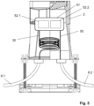
- Figure 1 shows a connection housing device 1 with a connection housing 2 and a stand 3.
- the connection housing 2 delimits a housing interior 4, which is accessible from above through an opening 5.
- the opening 5 is here closed with a lid 6, which can be removed upwards.
- connection housing 2 is equipped with two connection points 7.1, 7.2 on the underside. As discussed in detail below, an empty pipe 8.1 is inserted into the connection point 7.1, which then extends from an empty pipe strand to the connection housing 2. Depending on the application and procedure in detail, an empty connection pipe 8.2 is inserted into the connection point 7.2, which then connects the connection housing 2 to the distributor/user, for example a building.
- connection housing 2 is placed outside the building in the layer structure 10 of the street 15 (see also Fig. 2 ), so that there is an upper edge 2.1 of the connection housing 2 lies flush with an upper edge 9 of the layer structure 10, which is sketched in the left half of the picture.
- An upper layer 10.1 can be, for example, the paving layer (sidewalk) or asphalt surface layer (road), the layer 10.2 underneath can be a bed or a binder layer.
- the underlying layers 10.3, 10.4 represent support layers. If the connection housing 2 is positioned, the position of the upper edge 9 is already known (determined), even if the layer structure 10 is sometimes only created much later.
- Figure 2 illustrates various possibilities when used in existing buildings.
- a street is made accessible by laying fiber optics.
- buildings 20.1-20.4 are shown schematically as data user points 16, each of which stands on a building footprint 21.1-21.4.
- the sidewalk 22 is broken up and a trench is dug; this is not shown in detail in the schematic plan view.
- An empty pipe run 23 is laid in the trench; for each building 20.1-20.4 there is a respective data cable branch point 24.1-24.4.
- the respective properties 25 extend, with the property boundary 26 in between.
- the roadway 27 runs, which, like the sidewalk 22, is part of the street 15.
- connection housing 2.1-2.3 For buildings 20.1-20.3, for which no connection is desired (for the time being), a connection housing 2.1-2.3 is placed. Furthermore, because the trench has currently been dug, a respective empty pipe 8.1.1-8.1.3 is laid between the respective data cable branch point 24.1-24.3 and the respective connection housing 2.1-2.3, see also the overview Figure 1 for illustration.
- the trench can then be filled up and the layer structure 10 can be restored.
- connection housing 2.1 is located directly on the building base area 21.1, and in accordance with the main claim, not in the area of the street, but on the property 25.
- buildings 20.2, 20.3, a piece of property 25 has to be excavated for laying in the ground, but the effort required for this is significantly less than digging up the sidewalk 22.
- connection housings 2.2, 2.3 Due to their positioning in the layer structure 10 of the street 15, the connection housings 2.2, 2.3 are kept stable and cannot sink or tilt. This can prevent the empty pipes 8.1, 8.2 from slipping out and thus the data cable from kinking.
- the connection housing 2.1 is not provided in the layer structure 10 of the street 15, but is stabilized due to the positioning directly on the building 20.1.
- FIGs 3a , b illustrate in an analogue representation Figure 1 how a data cable 30 is laid through the empty pipe 8.1 into the housing interior 4. This is done with an excess length; an end section 30.1 of the data cable 30, taken away from an entry point 31 into the housing interior 4, has a length of around 10 m.
- Figure 3b illustrates how this end section 30.1 is then routed further to the data user or distribution point 16 through the previously or subsequently attached empty connection pipe 8.2, i.e. in the case of Fig. 2 to the building. Specifically, the end 30.2 of the data cable 30 is pushed into the empty pipe 8.2; when fully installed, it is then located within the building.
- connection housings 2.1-2.3 can be produced in the same work process in which the connection is placed through the empty pipe 28.
- a data cable 30 would then be pre-laid into each of the connection housings 2.1-2.3, with the corresponding end section 30.1 preferably being placed in a loop form (risk of breakage).
- the connection housings 2.1-2.3 are actually already equipped with data cables 30 during the advance installation.
- the positioning and connection via the empty pipes 8.1.1-8.1.3 alone is sufficient so that the sidewalk no longer has to be dug up.
- Figure 4 illustrates an application in a new development area.
- the sidewalk 22 and the roadway 27 of the street 15 are again shown, although these have not yet been created when the empty pipe string 23 is laid. In this case, no buildings have been built yet (at least not yet completely), which is why only the building footprints 21.1-21.4 are shown.
- connection housings 2.1-2.4 are placed on the property boundaries 26, but still on the sidewalk 22. This will not hinder later construction work on plots 25.
- connection housing 2.1 If the first building is then completed, for example on the building base area 21.1, an empty connecting pipe 8.2.1 is laid between the connection housing 2.1 and this building. From the node 29, the data cable is then routed into the building via the data cable branch point 24.1 and the connection housing 2.1. In this context, the data cables are also laid to the other connection housings 2.2-2.4; they can be used there analogously Figure 3a be filed. It then advantageously only has to be handled once at the node 29.
- Figure 5 illustrates an alternative to the procedure according to Figures 3a , b , namely the production of the user/distribution, in particular building connection via a further data cable 50.
- This is connected to the data cable 30 in the connection housing 2, in the present case by plugging them together in a plug housing 51.
- This has a sealed interior in which the data cables are stored 30.50 put together.
- Each of the data cables 30, 50 enters the connector housing 51 in a sealed manner.
- the plug housing can in principle have an access opening; a variant with two separate access openings 52.1, 52.2 can be preferred.
- Each opening 52.1, 52.2 is provided with its own closure, the opening 52.1 is opened to insert the data cable 30, the opening 52.2 to insert the data cable 50.
- FIG. 6 shows a further possible application, whereby the connection housing 2 is again placed between a data cable branch point 24 and a data user or distribution point 16.
- the latter is a radio unit 60, namely a WLAN module.
- This is or will be arranged in a lamp post 61 shown schematically here to provide a public WLAN network.
- the connection housing 2 is placed next to the lamp post 61 and connected to the data cable branching point 24 via the empty pipe 8.1.
- connection housing 2 is placed in each case (not necessarily on every lamp post, for example every second one can also be sufficient for sufficient network coverage). If the data cables are then later blown in from the node 29, the data cables can be laid in each connection housing 2 in one operation, analogous to the description above (see "New construction"), and the respective radio module 60 can then be connected gradually.
- the connection housings 2 can also be placed on lamp posts 61 if they are not yet or are not to be equipped with a radio module 60.
- the connection housing 2 can significantly simplify later retrofitting (no digging up the sidewalk 22).
- connection housing 2 can be analog in the connection housing 2 Figure 5 be moved (plug connection), the variant according to is preferred Figures 3a , b (looping through an excess length).
- the connection housing 2 can be opened for this purpose, for example, and a connection can then be drilled through a housing wall of the connection housing 2 and a base wall of the lamp post 61.
- connection housings 2 can be placed both on the initially unconnected buildings 20.1-20.3 and on lamp posts 61 (or traffic lights, etc.).
Description
Die vorliegende Erfindung betrifft ein Verfahren zum Bereitstellen einer Datenkabelanbindung für eine Datennutzer- oder Verteilerstelle, insbesondere für ein Gebäude.The present invention relates to a method for providing a data cable connection for a data user or distribution point, in particular for a building.
Aus der
Aus der
Aus einem Fachartikel "Hauff-Technik: Challenges and professional solutions for sealing of power cables in foundations of on shore wind turbines" ist die Verlegung von Stromkabeln durch dicke Fundamentwände mit speziellen Durchführungen bekannt.From a specialist article "Hauff-Technik: Challenges and professional solutions for sealing of power cables in foundations of on shore wind turbines" the laying of power cables through thick foundation walls with special bushings is known.
Aus der
Aus der
Der vorliegende Gegenstand richtet sich speziell auf das letzte Teilstück eines Datenkabelnetzes, nämlich die Anbindung des Nutzers/Verteilers bzw. Gebäudes an eine Datenkabel-Verzweigungsstelle. Bei dieser kann es sich insbesondere um einen Abzweig aus einem Strang handeln, der bspw. entlang einer Straße im Boden verläuft.The present subject is specifically aimed at the final section of a data cable network, namely the connection of the user/distributor or building to a data cable branch point. This can be particularly the case act as a branch from a strand that runs, for example, along a road in the ground.
Der vorliegenden Erfindung liegt das technische Problem zugrunde, ein vorteilhaftes Verfahren zur Anbindung an eine Datenkabel-Verzweigungsstelle anzugeben.The present invention is based on the technical problem of specifying an advantageous method for connecting to a data cable branch point.
Dies wird erfindungsgemäß mit dem Verfahren gemäß Anspruch 1 gelöst. Das Datenkabel bzw. ein Leerrohr dafür wird dabei nicht direkt von der Datenkabel-Verzweigungsstelle zu dem Nutzer/Verteiler bzw. Gebäude verlegt, sondern in bzw. über ein Anschlussgehäuse. Dieses wird im Bereich der Straße platziert, also im Falle des Gebäudes jedenfalls außerhalb der Gebäudegrundfläche, je nach Baustadium bzw. Anwendung (Neubau/Bestand) außerhalb des bereits errichteten Gebäudes oder der Fläche, auf welcher das Gebäude später errichtet wird. Das Anschlussgehäuse weist eine Öffnung auf, über die ein Gehäuseinnenraum zugänglich ist. Es wird zwischen der Datenkabel-Verzweigungsstelle und dem Nutzer/Verteiler bzw. Gebäude platziert, wobei
- die Öffnung des Anschlussgehäuses nach oben weist, also oberseitig liegt;
- das Anschlussgehäuse horizontal im Bereich einer Straße positioniert wird;
- das Anschlussgehäuse vertikal auf einer Höhe positioniert wird, die innerhalb einer fertigen Schichtaufbauhöhe der Straße liegt, wobei aber die Öffnung und damit der Gehäuseinnenraum von oben zugänglich bleibt.
- the opening of the connection housing faces upwards, i.e. is on the top side;
- the connection housing is positioned horizontally in the area of a street;
- the connection housing is positioned vertically at a height that lies within a finished layer structure height of the street, but the opening and thus the housing interior remain accessible from above.
Wird dann später der Straßenaufbau erstellt, also die Trag- und Deckschicht aufgebracht (z. B. Schotter aufgeschüttet, verdichtet und asphaltiert bzw. gepflastert), sitzt das Anschlussgehäuse in dem Schichtaufbau der Straße. Die Öffnung ist gleichwohl noch von oben ohne Entfernen der Deckschicht zugänglich, sie kann also im Wesentlichen bündig mit einer Oberkante des fertigen Schichtaufbaus liegen, bspw. der Deckschicht aus Asphalt oder Pflaster bzw. Platten.If the road structure is later created, i.e. the base and surface layer is applied (e.g. gravel is piled up, compacted and asphalted or paved), the connection housing sits in the layer structure of the road. The opening is nevertheless still accessible from above without removing the cover layer, so it can lie essentially flush with an upper edge of the finished layer structure, for example the cover layer made of asphalt or paving or slabs.
Mit dem Platzieren und Anschließen des Anschlussgehäuses an die Datenkabel-Verzweigungsstelle wird ein Zugangspunkt geschaffen, der das weitere Anschlie-ßen bzw. Erschließen der Datennutzer-/Verteilerstelle vereinfachen kann. Alternativ zu einem Gebäude (Büro- oder Wohngebäude) kann es sich hierbei bspw. auch um eine Antennenstation bzw. -einheit handeln (z. B. für öffentliches WLAN), siehe unten im Detail. Zur Veranschaulichung werden die Vorteile des Erfindungsgegenstands zunächst anhand der Erschließung eines Gebäudes diskutiert.By placing and connecting the connection housing to the data cable branch point, an access point is created that can simplify further connection or development of the data user/distribution point. As an alternative to a building (office or residential building), this can also be an antenna station or unit (e.g. for public WLAN), see below in detail. To illustrate this, the advantages of the subject matter of the invention are first discussed using the development of a building.
Dabei können sich je nach Anwendung (Neubau/Bestand) unterschiedliche Vorteile ergeben, was im Folgenden illustriert wird. Der Gegenstand richtet sich insbesondere auf eine Glasfaser-Erschließung, bevorzugt ist bzw. sind also die Datenkabel Glasfaserkabel.Depending on the application (new building/existing), different advantages can arise, which are illustrated below. The subject is particularly aimed at fiber optic access, so the data cables are preferably fiber optic cables.
Wird die Datenanbindung im Bestand nachgerüstet, kann die Netzverlegung typischerweise für ganze Straßenzüge bzw. Orts- oder Stadtteile erfolgen. Es wird dann die Straße, bspw. der Gehweg, aufgegraben und z. B. ein Kabelstrang verlegt, von dem bei jedem anzuschließenden Haushalt ein Kabel abgezweigt wird (an einer jeweiligen Datenkabel-Verzweigungsstelle). Der straßenseitige Graben wird dann wieder verfüllt und die zuvor aufgebrochene Deckschicht wird wiederhergestellt.If the data connection is retrofitted to existing buildings, the network can typically be laid for entire streets or towns or districts. The street, for example the sidewalk, is then dug up and z. B. a cable harness is laid, from which a cable is branched off for each household to be connected (at a respective data cable branch point). The roadside ditch is then backfilled and the previously broken surface layer is restored.
Die Erfinder haben festgestellt, dass sich hierbei jedoch meist nur der kleinere Teil der Anwohner bzw. Eigentümer für eine Nachrüstung sofort entscheidet (typischerweise 1/3). Weitere Anschlüsse werden dann erst später, nach und nach angefragt. Hierfür muss dann jeweils erneut aufgegraben, also insbesondere die Deckschicht aufgebrochen und ein Abzweig zu dem jeweiligen Gebäude verlegt werden, was erheblichen Aufwand bedeutet. Es muss ferner bei jeder Nachbelegung der Bodenaufbau dann auch wiederhergestellt werden (insbesondere die Deckschicht/der Belag).The inventors have found that usually only a small proportion of residents or owners decide to retrofit immediately (typically 1/3). Further connections will then only be requested later, gradually. For this purpose, each building must be dug up again, i.e. in particular the top layer must be broken up and a branch must be laid to the respective building, which means considerable effort. The floor structure must also be restored each time the floor is resurfaced (particularly the top layer/covering).
Demgegenüber bietet das erfindungsgemäße Vorgehen die Möglichkeit, bei den vorerst noch nicht angeschlossenen Gebäuden jeweils ein Anschlussgehäuse zu setzen. Es kann dann entweder sogar bereits das Datenkabel bis in das Anschlussgehäuse verlegt und dort (vorerst) verwahrt werden, oder es kann das Anschlussgehäuse zumindest über das Leerrohr angebunden sein. Soll das Gebäude dann später (nach der eigentlichen Erschließung des Straßenzugs) doch noch angeschlossen werden, muss je nach Position des Anschlussgehäuses zumindest nicht der Gehweg/die Straße aufgegraben werden, mitunter ist auch gar kein Aufgraben notwendig (wenn das Anschlussgehäuse direkt am Gebäude sitzt, siehe unten im Detail).In contrast, the procedure according to the invention offers the possibility of providing a connection housing for buildings that have not yet been connected set. The data cable can then either be laid into the connection housing and stored there (for the time being), or the connection housing can at least be connected via the empty pipe. If the building is to be connected later (after the street has actually been opened up), then depending on the position of the connection housing, at least the sidewalk/street does not have to be dug up, and sometimes no digging is necessary at all (if the connection housing is located directly on the building, see below in detail).
Auch wenn das Datenkabel nicht gleich bis in das Anschlussgehäuse vorverlegt wird, sondern dieses zunächst nur über das Leerrohr an die Datenkabel-Verzweigungsstelle angebunden ist, kann ein nachträgliches Anschließen des Gebäudes deutlich vereinfacht sein. Durch das Leerrohr kann dann nämlich das Datenkabel nachträglich eingeblasen werden, was über die Datenkabel-Verzweigungsstelle erfolgt.Even if the data cable is not routed straight into the connection housing, but is initially only connected to the data cable branching point via the empty conduit, subsequent connection to the building can be significantly simplified. The data cable can then be subsequently blown in through the empty pipe, which is done via the data cable branching point.
Das erfindungsgemäße Vorgehen ist jedoch nicht nur bei einer Erschließung im Bestand, sondern auch im Neubau von Vorteil. In einem Neubaugebiet mag es zwar auf den ersten Blick weniger aufwendig und kostengünstiger erscheinen, die einzelnen Gebäude bzw. Gebäudegrundflächen jeweils direkt anzuschließen, also das Datenkabel bzw. Leerrohr dafür von der Datenkabel-Verzweigungsstelle direkt bis zum Gebäude bzw. dessen Grundfläche zu verlegen. Die Erfinder haben jedoch festgestellt, dass der Baufortschritt auf den einzelnen Grundstücken in der Praxis erheblich divergieren kann, sodass einige Gebäude bspw. schon bezogen werden, während sich andere noch im Rohbaustadium befinden, wenn überhaupt. Der Netzbetreiber kann deshalb nicht in einem Zug das gesamte Gebiet erschlie-ßen, sondern wiederum nur nach und nach.However, the procedure according to the invention is not only advantageous when developing existing buildings, but also in new buildings. In a new development area, it may seem at first glance less complex and more cost-effective to connect the individual buildings or building floor areas directly, i.e. to lay the data cable or empty conduit from the data cable branch point directly to the building or its floor area. However, the inventors have found that in practice the construction progress on individual properties can vary considerably, so that some buildings, for example, have already been occupied while others are still in the shell construction stage, if at all. The network operator can therefore not open up the entire area in one go, but only gradually.
Das erfindungsgemäße Vorgehen eröffnet auch hier eine Möglichkeit der Vorverlegung, bspw. bis an das jeweilige Grundstück. Die Anschlussgehäuse können, wo später die Straße, insbesondere der Gehweg verläuft, bspw. an den Grundstückgrenzen platziert werden. Unabhängig von ihrer Position im Einzelnen kann der Netzbetreiber die einzelnen Datenkabel (für die einzelnen Gebäude bzw. Gebäudegrundflächen) dann in einem Zug bis in die Anschlussgehäuse verlegen, also in einem Arbeitsdurchgang (innerhalb eines Arbeitstages oder mehrerer zusammenhängender). Dieses Vorverlegen bis in die Anschlussgehäuse kann bspw. erfolgen, sobald der erste Haushalt seinen Datenanschluss erhält. Benötigen dann nach und nach die übrigen Haushalte ihren Datenanschluss, ist der Aufwand für die Verlegung dieser letzten Meter deutlich geringer als das Verlegen von der Datenkabel-Verzweigungsstelle aus bzw. über diese. Letzteres erfordert nämlich in der Regel mindestens zwei Techniker, die letzten Meter können auch von einem einzelnen Techniker verlegt werden.The procedure according to the invention also opens up the possibility of bringing it forward, for example to the respective property. The connection housings can be placed where the street, especially the sidewalk, will later run, for example at the property boundaries. Regardless of their position in detail The network operator then lays the individual data cables (for the individual buildings or building floor areas) in one go into the connection housing, i.e. in one work pass (within one working day or several consecutive working days). This forward movement into the connection housing can be done, for example, as soon as the first household receives its data connection. If the remaining households then gradually need their data connection, the effort involved in laying these last meters is significantly less than laying them from or via the data cable branch point. The latter usually requires at least two technicians; the last few meters can also be laid by a single technician.
Generell werden die Datenkabel von einem Knotenpunkt aus verlegt, an dem mehrere, also die einzelnen Datenkabelverzweigungsstellen zusammenlaufen. Von diesem Knotenpunkt kann sich, wie vorstehend geschildert, ein Kabel- bzw. Leerrohrstrang entlang der Straße erstrecken (im Erdreich), wobei an den Gebäuden (bzw. allgemein Nutzern/Verteilern) jeweils ein Kabel/Leerrohr abgeht. An dem übergeordneten Knotenpunkt kann bspw. ein Verteilerkasten (Spleißkasten) oder eine Spleißmuffe angeordnet sein. Zwischen dem Knotenpunkt und den einzelnen Gebäuden (Nutzern/Verteilern) kann eine gewisse Wegstrecke liegen, und die Datenkabel werden mit einem Spezialwerkzeug in die Leerrohre eingeblasen und damit über entsprechend große Strecken vorgeschoben. In dieser Hinsicht ist das vorstehend geschilderte Vorgehen, also das Vorverlegen vorerst nicht benötigter Datenkabel in einem Arbeitsgang, insoweit von Vorteil, als dann das entsprechende Spezialwerkzeug (Einblasvorrichtung) nur einmal an dem Knotenpunkt bereitgestellt werden muss. Die Arbeiten am Knotenpunkt können auch hinsichtlich der Kabelverbindung/-verzweigung dort Spezialwerkzeug erfordern, bspw. einen Kabelspleißer im Falle der bevorzugten Glasfaserkabel. Auch dieser muss dann nur einmal samt entsprechend geschultem Personal bereitgestellt werden, jedenfalls am Knotenpunkt (mitunter auch generell, vgl. insbesondere die Variante "Stecker" unten).In general, the data cables are laid from a node at which several, i.e. individual data cable branch points, converge. From this junction, as described above, a cable or empty conduit can extend along the street (in the ground), with a cable/empty conduit leading off each building (or generally users/distributors). For example, a distribution box (splice box) or a splice sleeve can be arranged at the higher-level node. There may be a certain distance between the node and the individual buildings (users/distributors), and the data cables are blown into the empty conduits using a special tool and thus advanced over correspondingly long distances. In this regard, the procedure described above, i.e. pre-laying data cables that are not initially required in one operation, is advantageous in that the corresponding special tool (blowing device) only has to be provided once at the node. The work at the junction may also require special tools regarding the cable connection/branch there, for example a cable splicer in the case of the preferred fiber optic cables. This then only needs to be provided once with appropriately trained personnel, at least at the junction (sometimes also in general, see in particular the “plug” variant below).
Im Falle des Gebäudes sitzt das straßenseitig angeordnete Anschlussgehäuse außerhalb der Gebäudegrundfläche, also außerhalb der von dem Gebäude eingenommenen Fläche inklusive der Wände, also der nach den Außenmaßen genommene Brutto-Grundfläche. Diese kann kleiner sein als die überbaute Fläche (Dachüberstand). Das Anschlussgehäuse wird zwar außerhalb der Grundfläche platziert, kann jedoch durchaus innerhalb der überbauten Fläche liegen, bspw. im Falle eines direkt an der Gebäudeaußenwand platzierten Anschlussgehäuses. Letzteres kommt insbesondere bei einer Nachrüstung im Bestand in Betracht. Andererseits kann jedoch auch ein gewisser Mindestabstand zur Gebäudegrundfläche bevorzugt sein.In the case of the building, the connection housing arranged on the street side is located outside the building footprint, i.e. outside the area occupied by the building including the walls, i.e. the gross floor area based on the external dimensions. This can be smaller than the built-over area (roof overhang). Although the connection housing is placed outside the base area, it can certainly be within the built-up area, for example in the case of a connection housing placed directly on the outer wall of the building. The latter is particularly important when retrofitting existing buildings. On the other hand, however, a certain minimum distance from the building footprint may also be preferred.
Aufgrund der Platzierung des Anschlussgehäuses auf der Straße (in anderen Worten: an den Straßenrand grenzend), insbesondere dem Gehweg, etwa an die Grundstücksgrenze grenzend, muss dann bei einer nachträglichen Belegung der Gehweg / die Straße nicht nochmals aufgegraben werden, es kann bspw. auf bzw. von dem Grundstück seitlich an das Anschlussgehäuse herangegraben werden. Generell meint die "horizontale" Positionierung des Anschlussgehäuses "im Bereich einer Straße", dass das Anschlussgehäuse mit dem Schichtaufbau der Stra-ße vertikal fluchtend angeordnet ist. Ist die Straße fertiggestellt, sitzt das Anschlussgehäuse in dem Schichtaufbau der Straße (weil es zudem auf einer vertikalen Höhe innerhalb der fertigen Schichtaufbauhöhe platziert wird).Due to the placement of the connection housing on the street (in other words: bordering on the edge of the street), in particular the sidewalk, for example bordering on the property line, the sidewalk/street does not have to be dug up again if it is subsequently occupied; it can, for example or dug from the side of the property towards the connection housing. In general, the "horizontal" positioning of the connection housing "in the area of a street" means that the connection housing is arranged vertically aligned with the layer structure of the street. Once the road is completed, the junction box sits within the road's layer structure (because it is also placed at a vertical height within the finished layer structure height).
Der "Schichtaufbau" umfasst insbesondere eine Tragschicht, wobei auch mehrere aufeinandergesetzte Tragschichten möglich sind. Das Baustoffgemisch der Tragschicht kann insbesondere Schotter umfassen, dieser wird verdichtet. Darauf kommt eine Deckschicht, bspw. Asphalt oder Platten bzw. Pflastersteine, im Allgemeinen ist jedoch bspw. auch eine ungebundene Deckschicht möglich (eine Schotterschicht im Falle eines Schotterwegs). Das Platzieren im Schichtaufbau der Straße ist bspw. insoweit von Vorteil, als diese Schicht(en) verdichtet ist bzw. sind, also eine gute mechanische Stabilität bieten. Dies ist im vorliegenden Zusammenhang von besonderer Bedeutung, weil die Datenkabel bzw. die vergleichsweise dünnen Leerrohre dafür relativ empfindlich sind. Die Rohre (aus Kunststoff) bzw. Datenkabel können leicht abknicken, wobei die Glasfasern brechen können und ihre Funktion verlieren. Würde man das Anschlussgehäuse nicht im definierten Schichtaufbau der Straße, sondern an beliebiger Stelle im Erdreich platzieren, kann es bei Setzungen im Erdreich zu einem Abknicken bzw. anderweitigen Beschädigung des Leerrohres/Datenkabels kommen. Der Schichtaufbau der Straße wird hingegen definiert verdichtet, was z. B. mit einem dynamischen Plattendruckgerät und/oder einer Rammsonde (Gleichmäßigkeit der Verdichtung) überprüft werden kann (bzw. im Straßenbau überprüft wird).The “layer structure” includes in particular a base layer, although several base layers placed one on top of the other are also possible. The building material mixture of the base layer can in particular include gravel, which is compacted. This is followed by a top layer, for example asphalt or slabs or paving stones, but in general an unbound top layer is also possible (a gravel layer in the case of a gravel path). Placing it in the layer structure of the road is, for example, an advantage insofar as this layer(s) is or are compacted, i.e. offer good mechanical stability. This is of particular importance in the present context because the data cables or the comparatively thin empty conduits are relatively sensitive to this. The pipes (from Plastic) or data cables can easily kink, causing the glass fibers to break and lose their function. If the connection housing were not placed in the defined layer structure of the street, but at any point in the ground, settlement in the ground could result in the empty conduit/data cable being bent or otherwise damaged. The layer structure of the road, on the other hand, is compacted in a defined manner, which e.g. B. can be checked with a dynamic plate pressure device and/or a ramming probe (uniformity of compaction) (or is checked in road construction).
Bei der Montage bzw. Herstellung des Schichtaufbaus der Straße wird dann also seitlich um das Anschlussgehäuse herum z. B. eine Schotterschicht verdichtet, etwa mit einer Rüttelplatte. Bevorzugt gibt es mehrere aufeinander gesetzte, also nacheinander hergestellte Schotterschichten, die jeweils um das Anschlussgehäuse herum verdichtet werden. Das Anschlussgehäuse ist dann, speziell nach Aufbringen der Deckschicht, definiert und stabil eingebaut. Auch mit Blick auf einen solchen Einbau hat das Anschlussgehäuse bevorzugt eine Wandstärke (Gehäusewanddicke) von mindestens 5 mm, 7 mm, bzw. 8 mm, mit möglichen (davon unabhängigen) Obergrenzen bei z. B. höchstens 25 mm, 20 mm bzw. 15 mm (eine entsprechende Wandstärke soll die Gehäusewand nicht nur punktuell, sondern großflächig haben, bspw. über mindestens 70 %, 80 % bzw. 90 % der Gehäusewandfläche, bevorzugt über 100 %). Damit kann insbesondere auch im Falle des bevorzugt aus Kunststoffmaterial vorgesehenen Anschlussgehäuses eine hinreichende Stabilität erreicht werden. Generell kann das Anschlussgehäuse auch aus Metall vorgesehen sein (z. B. Druckguss), bevorzugt ist ein Kunststoffmaterial (Hartkunststoff), z. B. Polyamid, insbesondere Glasfaser-verstärkt, oder ein Copolymer-Material.When assembling or producing the layer structure of the road, z. B. compact a layer of gravel, for example with a vibrating plate. There are preferably several layers of gravel placed one on top of the other, i.e. produced one after the other, each of which is compacted around the connection housing. The connection housing is then installed in a defined and stable manner, especially after the top layer has been applied. Even with such an installation in mind, the connection housing preferably has a wall thickness (housing wall thickness) of at least 5 mm, 7 mm or 8 mm, with possible (independent) upper limits at e.g. B. at most 25 mm, 20 mm or 15 mm (the housing wall should have a corresponding wall thickness not only at points, but over a large area, for example over at least 70%, 80% or 90% of the housing wall area, preferably over 100%). This means that sufficient stability can be achieved, particularly in the case of the connection housing, which is preferably made of plastic material. In general, the connection housing can also be made of metal (e.g. die-casting); a plastic material (hard plastic), e.g. B. polyamide, especially glass fiber reinforced, or a copolymer material.
Aufgrund der erforderlichen Abstimmung mit den Tiefbau- /Straßenbauunternehmen etc. mag die Positionierung im Straßenbereich zwar zunächst nachteilig erscheinen, in der Gesamtschau überwiegen jedoch die technischen Vorteile. Der Begriff "Straße" umfasst hierbei sowohl die Fahrbahn als auch den Gehweg, weitere Bestandteile können ein Radweg und auch Mittel- bzw. Seitenstreifen (Überland/Autobahn) sein. Prinzipiell kann das Anschlussgehäuse in jedem der genannten Bereiche platziert werden (im Bereich der Fahrbahn oder des Radwegs oder des Mittel-/Seitenstreifens oder des Gehwegs), bevorzugt ist bei einer üblichen Bebauung im örtlichen/städtischen Bereich eine Positionierung im Bereich des Gehwegs, besonders bevorzugt an der Grundstücksgrenze (am Straßenrand).Due to the necessary coordination with civil engineering/road construction companies, etc., positioning in the road area may initially seem disadvantageous, but overall the technical advantages outweigh the disadvantages. The term “street” includes both the roadway and the sidewalk; other components can include a cycle path and also middle or middle streets. Be a shoulder (overland/motorway). In principle, the connection housing can be placed in any of the areas mentioned (in the area of the roadway or the cycle path or the median/side strip or the sidewalk); in a usual development in the local/urban area, positioning in the area of the sidewalk is particularly preferred at the property line (on the side of the road).
Das Anschlussgehäuse kann dabei auch direkt an die Gebäudegrundfläche grenzend platziert werden, wenn bspw. im städtischen Bereich die Außenwand direkt am Gehweg liegt. Es kann es aber andererseits zwischen Gebäudegrundfläche und Anschlussgehäuse auch einen Mindestabstand von mindestens 1 m, 2 m bzw. 3 m geben. Mögliche Obergrenzen, die im Einzelnen auch von der Grundstücksgröße abhängen, können bspw. bei höchstens 50 m, 40 m, 30 m, 20 m, 15 m bzw. 10 m liegen.The connection housing can also be placed directly adjacent to the building footprint, for example if the outer wall is directly on the sidewalk in an urban area. On the other hand, there can also be a minimum distance of at least 1 m, 2 m or 3 m between the building footprint and the connection housing. Possible upper limits, which also depend on the size of the property, can be, for example, a maximum of 50 m, 40 m, 30 m, 20 m, 15 m or 10 m.
Wie bereits erwähnt, wird das Anschlussgehäuse auf einer Höhe innerhalb der fertigen Schichtaufbauhöhe der Straße platziert. Dies meint nicht, dass zur Erfüllung des hauptanspruchsgemäßen Gegenstands dann auch noch der Schichtaufbau erstellt werden muss (was in der Praxis in der Regel von anderen Arbeitern und mitunter auch erst deutlich später vorgenommen wird). Ist der Schichtaufbau dann fertig erstellt, sitzt das Anschlussgehäuse jedoch innerhalb davon. Bevorzugt liegt eine Oberkante des Anschlussgehäuses im Wesentlichen bündig mit der Oberkante des Schichtaufbaus (deren Lage ist vorab bekannt), also mit der Oberkante der Deckschicht. "Im Wesentlichen bündig" meint bspw. einen Versatz um weniger als 3 cm, 2 cm bzw. 1 cm. Im Rahmen der technisch üblichen Genauigkeit ist ein bündiger Einbau bevorzugt (0 cm). Das Anschlussgehäuse reicht bevorzugt in die Tragschicht bzw. -schichten hinein, erstreckt sich also bspw. mindestens über eine Höhe von 20 cm, 25 cm bzw. 30 cm (mit einer möglichen Obergrenze bei höchstens 50 cm, siehe unten im Detail).As previously mentioned, the junction box is placed at a height within the finished strata height of the road. This does not mean that in order to fulfill the main claim, the shift structure must also be created (which in practice is usually done by other workers and sometimes only much later). Once the layer structure has been created, the connection housing sits within it. Preferably, an upper edge of the connection housing lies essentially flush with the upper edge of the layer structure (the position of which is known in advance), i.e. with the upper edge of the cover layer. “Substantially flush” means, for example, an offset of less than 3 cm, 2 cm or 1 cm. As part of the usual technical accuracy, flush installation is preferred (0 cm). The connection housing preferably extends into the base layer or layers, i.e. extends, for example, at least over a height of 20 cm, 25 cm or 30 cm (with a possible upper limit of at most 50 cm, see below in detail).
Die Öffnung des Anschlussgehäuses liegt oberseitig, bevorzugt ist sie mit einem reversibel herausnehm- und wiedereinsetzbaren Deckel verschlossen. Der Deckel kann sich bevorzugt ein Stück weit in die Öffnung hineinerstrecken, was einen sicheren Sitz gewährleisten kann. Es kann insbesondere ein verschließbarer Deckel vorgesehen sein, um einem unbefugten Zugang zu dem Gehäuseinneren vorzubeugen. Der Deckel lässt sich dann also nur mit einem speziellen Schlüssel öffnen. Das Anschlussgehäuse kann, von dem Deckel abgesehen, für sich einstückig sein; es kann aber auch mehrteilig vorgesehen sein, insbesondere in ein Ober- und ein Unterteil unterteilt sein. Diese Teile können zur Höhenpassung vertikal zueinander verschiebbar sein, also teleskopartig eine gewisse Anpassung der vertikalen Erstreckung des Anschlussgehäuses ermöglichen.The opening of the connection housing is on the top side and is preferably closed with a reversibly removable and re-insertable cover. The lid can preferably extend a little way into the opening, which can ensure a secure fit. In particular, a lockable lid can be provided to prevent unauthorized access to the interior of the housing. The lid can then only be opened with a special key. The connection housing can, apart from the cover, be in one piece; However, it can also be provided in several parts, in particular divided into an upper and a lower part. These parts can be vertically displaceable relative to one another for height adjustment, i.e. they can telescopically enable a certain adjustment of the vertical extent of the connection housing.
Mit Blick auf die bevorzugten Glasfaserkabel, die bestimmte minimale Biegeradien haben (Bruchgefahr), kann eine Öffnung mit gewissen Mindestmaßen bevorzugt sein. Eine mittlere Öffnungsweite, die sich als Mittelwert der größten und kleinsten horizontalen Erstreckung der Öffnung ergibt und im bevorzugten Fall der Kreisform dem Kreisdurchmesser entspricht, kann bspw. bei mindestens 5 cm liegen, weiter und besonders bevorzugt mindestens 10 cm bzw. 12 cm. Mögliche Obergrenzen können (davon unabhängig) bspw. bei höchstens 40 cm bzw. 30 cm liegen. Der Deckel ist dann der Öffnung entsprechend bemessen.With regard to the preferred fiber optic cables, which have certain minimum bend radii (risk of breakage), an opening with certain minimum dimensions may be preferred. A mean opening width, which results from the average of the largest and smallest horizontal extent of the opening and, in the preferred case of the circular shape, corresponds to the circular diameter, can be, for example, at least 5 cm, further and particularly preferably at least 10 cm or 12 cm. Possible upper limits (regardless of this) can be, for example, a maximum of 40 cm or 30 cm. The lid is then sized according to the opening.
Wie vorstehend dargelegt, können sich vielfältige Vorteile ergeben, wenn die "Datennutzer- oder -verteilerstelle" ein Gebäude ist, bspw. ein Büro- oder Wohngebäude, wobei sowohl ein Mehrfamilienhaus als auch insbesondere ein Einfamilienhaus infrage kommt. Wie eingangs erwähnt, kann es sich bei der "Datennutzer-bzw. -verteilerstelle" jedoch auch um eine Antennenstation bzw. -einheit handeln, bspw. für öffentliches WLAN. Eine solche Antenneneinheit kann für sich (freistehend) vorgesehen sein, sie kann aber bspw. auch Teil einer Straßenlaterne oder Ampel sein (angesetzt oder auch baulich integriert).As explained above, a variety of advantages can arise if the “data user or distribution point” is a building, for example an office or residential building, with both an apartment building and, in particular, a single-family home being possible. As mentioned at the beginning, the “data user or distribution point” can also be an antenna station or unit, for example for public WLAN. Such an antenna unit can be provided on its own (free-standing), but it can also be part of a street lamp or traffic light (attached or structurally integrated), for example.
Im fertig montierten Zustand ist die Antenneneinheit dann mittels des Datenkabels über die Datenkabel-Verzweigungsstelle mit dem Knotenpunkt verbunden, über das Datenkabel werden Daten zu und auch von der Antenneneinheit übertragen, diese setzt das drahtgebundene Signal in ein Funksignal um. Dies kann auch ein Mobilfunksignal sein, es kann sich bei der Datennutzer- oder -verteilerstelle also bspw. auch um eine Mobilfunkstation handeln (z. B. für 5G). Eine solche Datennutzer- bzw. -verteilerstelle kann auch ein Technikgebäude umfassen, durch welches das Datenkabel geführt wird. Das Anschlussgehäuse wird dann außerhalb dieses Technikgebäudes im Bereich der Straße platziert, vgl. die vorstehenden Anmerkungen.When fully assembled, the antenna unit is then connected to the node via the data cable via the data cable branching point. Data is transmitted to and from the antenna unit via the data cable, which converts the wired signal into a radio signal. This can also be a Be a mobile phone signal, so the data user or distribution point can also be a mobile phone station (e.g. for 5G). Such a data user or distribution point can also include a technical building through which the data cable is routed. The connection housing is then placed outside this technical building in the street area, see the comments above.
Prinzipiell können sich bei der Anwendung "Antenneneinheit bzw. -station" dieselben Vorteile ergeben, wie vorstehend anhand der Gebäude geschildert. Wird bspw. ein Ortsteil bzw. Straßenzug erschlossen (die Straße aufgegraben und ein Leerrohrstrang verlegt, vgl. im Detail die vorstehenden Anmerkungen zum "Bestand"), ist nicht nur für die Büro-/Wohngebäude eine Vorverlegung möglich, sondern bspw. auch zur Errichtung eines öffentlichen WLAN-Netzes. Dazu kann ein jeweiliges Anschlussgehäuse bspw. an, also neben einer Laterne platziert werden, bevorzugt direkt neben dem Laternenpfosten bzw. einem Sockel. Die Laterne kann dann später für die Antenneneinheit eine Halterungsfunktion übernehmen, zudem ist dort auch Stromanschluss verfügbar (für den Umsetzer bzw. Konverter). Durch ein entsprechendes Platzieren von Anschlussgehäusen entlang der Straße, bspw. bei jeder oder jeder n-ten Laterne, kann ein Aufbau eines solchen WLAN-Netzes veranlagt werden. Es muss dann später nicht nochmals gesondert aufgegraben werden, vgl. die vorstehenden Anmerkungen. Auch wenn der Aufbau des WLAN-Netzes bereits beschlossen ist, können die bei den Laternen platzierten Anschlussgehäuse das Prozedere vereinfachen. Analog der vorstehenden Schilderung können die Datenkabel nämlich in einem Arbeitsgang vom Knotenpunkt zu den einzelnen Anschlussgehäusen verlegt werden, die eigentliche Montage an den einzelnen Laternen kann dann nach und nach erfolgen.In principle, the “antenna unit or station” application can have the same advantages as described above with reference to the buildings. If, for example, a district or street is developed (the street is dug up and an empty pipe line is laid, see the above comments on the "existing" in detail), advance relocation is possible not only for the office/residential buildings, but also for construction, for example a public WiFi network. For this purpose, a respective connection housing can be placed, for example, on, i.e. next to, a lantern, preferably directly next to the lamp post or a base. The lantern can then later take on a holding function for the antenna unit, and a power connection is also available there (for the converter). By appropriately placing connection housings along the street, for example at every or every nth lantern, such a WLAN network can be set up. It then does not have to be dug up again later, see the comments above. Even if the setup of the WiFi network has already been decided, the connection housings placed near the lanterns can simplify the process. Analogous to the description above, the data cables can be laid from the node to the individual connection housings in one operation; the actual assembly on the individual lanterns can then be carried out gradually.
Bevorzugte Ausgestaltungen finden sich in der vorliegenden Beschreibung, inklusive der Figuren, und den abhängigen Ansprüchen. In der Darstellung der Merkmale wird dabei nicht immer im Einzelnen zwischen Verfahrens- bzw. Verwendungs- oder Vorrichtungsaspekten unterschieden, jedenfalls implizit bezieht sich die Offenbarung auf sämtliche Anspruchskategorien. Wird also bspw. ein für einen bestimmten Einbau geeignetes Anschlussgehäuse beschrieben, ist dies auch als Offenbarung einer entsprechenden Verwendung bzw. des entsprechenden Verfahrens zu lesen (und umgekehrt).Preferred embodiments can be found in the present description, including the figures, and the dependent claims. In the presentation of the features, a detailed distinction is not always made between aspects of the method or use or device; at least implicitly, the disclosure refers to all claim categories. So, for example, it becomes one for one A connection housing suitable for a particular installation is described, this can also be read as a disclosure of a corresponding use or method (and vice versa).
Hauptanspruchsgemäß wird zwischen der Datenkabelverzweigungsstelle und dem Anschlussgehäuse das Datenkabel in einem Leerrohr für dieses verlegt. Wird das Datenkabel in dem Anschlussgehäuse dann zeitweilig in Schleifenform abgelegt (bis das entsprechende Gebäude bzw. der Nutzer/Verteiler tatsächlich angeschlossen wird, siehe vorne), wird auch in diesem Fall ein Leerrohr verlegt und das Datenkabel eingeblasen.According to the main claim, the data cable is laid in an empty pipe for this between the data cable branching point and the connection housing. If the data cable is then temporarily stored in the connection housing in the form of a loop (until the corresponding building or user/distributor is actually connected, see above), an empty pipe is also laid in this case and the data cable is blown in.
Erfindungsgemäß wird also zwischen der Datenkabel-Verzweigungsstelle und dem Anschlussgehäuse ein Leerrohr verlegt, das zum Verlegen des Datenkabels genutzt wird. Das Leerrohr kann bspw. einen Außendurchmesser von höchstens 30 mm, 25 mm, 20 mm bzw. 15 mm haben (eine mögliche Untergrenze kann bspw. bei mindestens 7 mm bzw. 10 mm liegen). Bei einer Wandstärke von 1-2 mm steht ein Innenquerschnitt zur Verfügung, in dem das Datenkabel gut geführt ist.According to the invention, an empty pipe is laid between the data cable branch point and the connection housing, which is used to lay the data cable. The empty pipe can, for example, have an outer diameter of at most 30 mm, 25 mm, 20 mm or 15 mm (a possible lower limit can be, for example, at least 7 mm or 10 mm). With a wall thickness of 1-2 mm, an internal cross section is available in which the data cable is well routed.
Generell wird das Leerrohr auf einer Höhe innerhalb der fertigen Schichtaufbauhöhe der Straße bzw. des Bodens verlegt, also unterhalb der Oberkante der fertigen Deckschicht (Pflaster/Platten bzw. Asphalt). Es kann bspw. mindestens 10 cm, 20 cm, 30 cm bzw. 40 cm unterhalb letzterer verlaufen, mit möglichen Obergrenzen bei höchstens 1,5 m, 1,2 m bzw. 1 m. Bevorzugt liegt das Leerrohr über die gesamte Strecke zwischen Datenkabel-Verzweigungsstelle und Anschlussgehäuse im Erdreich, also unterhalb der Oberkante des Schichtaufbaus.In general, the empty pipe is laid at a height within the finished layer structure height of the road or ground, i.e. below the upper edge of the finished surface layer (paving/slabs or asphalt). For example, it can run at least 10 cm, 20 cm, 30 cm or 40 cm below the latter, with possible upper limits of at most 1.5 m, 1.2 m or 1 m. The empty conduit preferably lies over the entire distance between the data cable -Branch point and connection housing in the ground, i.e. below the upper edge of the layer structure.
Wie bereits erwähnt, wird das Datenkabel, wenn das Leerrohr belegt wird, in bevorzugter Ausgestaltung mit einer Überlänge in das Anschlussgehäuse verlegt. Im fertig in das Anschlussgehäuse verlegten Zustand soll dann ein Endabschnitt des Datenkabels eine Länge von mindestens 1 m haben, wobei mindestens 2 m, 3 m, 4 m, 5 m, 6 m, 7 m, 8 m, 9 m bzw. 10 m weitere bevorzugte Untergrenzen sind. Mögliche Obergrenzen können bspw. höchstens 30 m, 20 m bzw. 15 m liegen. Konkret wird diese Länge zwischen der Eintrittsstelle, an welcher das Datenkabel aus dem Leerrohr in das Gehäuseinnere eintritt, bis zum Ende des Datenkabels genommen (dem Ende, das außerhalb des Leerrohres liegt, das also in einer Richtung von der Datenkabel-Verzweigungsstelle zu dem Anschlussgehäuse liegt).As already mentioned, when the empty pipe is occupied, the data cable is laid in the connection housing with an excess length in a preferred embodiment. When fully installed in the connection housing, one end section of the data cable should have a length of at least 1 m, with at least 2 m, 3 m, 4 m, 5 m, 6 m, 7 m, 8 m, 9 m or 10 m are further preferred lower limits. Possible upper limits can, for example, be a maximum of 30 m, 20 m or 15 m. Specifically, this length is taken between the entry point at which the data cable enters from the empty conduit into the interior of the housing to the end of the data cable (the end that lies outside the empty conduit, which is therefore in a direction from the data cable branching point to the connection housing ).
Bei einer bevorzugten Ausführungsform kann die Überlänge, also der Endabschnitt, dann vorübergehend in dem Anschlussgehäuse, also im Gehäuseinneren abgelegt werden. Dazu wird der Endabschnitt bevorzugt in Schleifenform gebracht, womit sich zuverlässig minimale Biegeradien nicht unterschreiten lassen. Es kann bspw. eine Kassette vorgesehen sein, also eine Ablagefläche mit Stegen bzw. Haken darauf, deren Abstand zueinander die Größe der Schleifenform vorgibt. Eine entsprechende Halterung für die Schleife kann bspw. direkt an der Gehäuseinnenwand bzw. als anderweitig integraler Teil des Gehäuses selbst vorgesehen sein, die Kassette kann aber auch herausnehm- und wiedereinsetzbar vorgesehen sein. Das Anschlussgehäuse kann dann bspw. eine Aufnahme zum Einhängen bzw. -schieben oder -clipsen der Kassette aufweisen.In a preferred embodiment, the excess length, i.e. the end section, can then be temporarily stored in the connection housing, i.e. inside the housing. For this purpose, the end section is preferably made into a loop shape, which means that the bending radii cannot be reliably undercut. For example, a cassette can be provided, i.e. a storage area with webs or hooks on it, the distance between which determines the size of the loop shape. A corresponding holder for the loop can, for example, be provided directly on the inner wall of the housing or as an otherwise integral part of the housing itself, but the cassette can also be designed to be removable and reinsertable. The connection housing can then, for example, have a receptacle for hanging, pushing or clipping the cassette.
Bevorzugt wird die Öffnung des Anschlussgehäuses nach dem schleifenförmigen Ablegen des Endabschnitts verschlossen, wird also der Deckel auf- bzw. eingesetzt. Wird das Datenkabel nur kurzzeitig abgelegt und bspw. noch am selben Arbeitstag weiter zum Gebäude bzw. Nutzer/Verteiler verlegt, kann auch ein schleifenförmiges Ablegen ohne Verschließen des Deckels Vorteile bieten, kann das Datenkabel nämlich in dem Gehäuseinneren etwas geschützt sein.The opening of the connection housing is preferably closed after the end section has been laid down in a loop, i.e. the cover is opened or inserted. If the data cable is only stored for a short time and, for example, moved to the building or user/distributor on the same working day, storing it in a loop without closing the lid can also offer advantages, as the data cable can be somewhat protected inside the housing.
Die Verlegung zwischen Anschlussgehäuse und Gebäude bzw. Nutzer/Verteiler erfolgt bevorzugt ebenfalls im Erdreich, besonders bevorzugt wird hierfür zunächst wiederum ein Leerrohr (Anschluss-Leerrohr) verlegt, durch welches dann das Datenkabel geschoben werden kann. Im Zuge einer Nachbelegung muss hierfür zwar nochmals ausgegraben werden, allerdings nur auf dem Grundstück, nicht im öffentlichen Raum (Gehweg/Straße), was einen entsprechend geringeren Aufwand bedeutet. Das Anschlussgehäuse wird im Falle eines Gebäudes nämlich bevorzugt direkt an die Grundstücksgrenze gesetzt.The installation between the connection housing and the building or user/distributor is preferably also carried out in the ground; for this purpose, it is particularly preferred to first lay an empty pipe (connection empty pipe) through which the data cable can then be pushed. In the course of reoccupancy, this requires excavation again, but only on the property, not in public spaces (sidewalk/street), which requires correspondingly less effort means. In the case of a building, the connection housing is preferably placed directly on the property boundary.
Das Datenkabel bzw. der Endabschnitt wird bevorzugt derart von dem Anschlussgehäuse zum Gebäude verlegt, dass das Ende des Endabschnitts dann im Gebäude liegt. Dort liegt also der Abschlusspunkt der Linientechnik. In diesem Fall erstreckt sich das Datenkabel dann unterbrechungsfrei von diesem im Gebäudeinneren über das Anschlussgehäuse zu der Datenkabel-Verzweigungsstelle (in der Regel über diese hinaus bis zu einem Knotenpunkt). "Unterbrechungsfrei" meint insoweit ohne Verbindungstelle dazwischen (insbesondere ohne Spleißstelle). Dieses Vorgehen kann bspw. insoweit von Vorteil sein, als dann in dem Anschlussgehäuse keine "komplexeren" Arbeiten am Datenkabel erforderlich sind, also bspw. kein Spleißgerät zu dem Anschlussgehäuse geschafft werden muss. Zudem kann das Datenkabel in dem Anschlussgehäuse etwas "exponiert" gegenüber Umwelteinflüssen sein, weswegen ein unterbrechungsfreier Verlauf dort vorteilhaft sein kann.The data cable or the end section is preferably laid from the connection housing to the building in such a way that the end of the end section is then in the building. This is where the final point of the line technology lies. In this case, the data cable then extends uninterrupted from inside the building via the connection housing to the data cable branch point (usually beyond this to a node). In this respect, “uninterrupted” means without a connection point in between (in particular without a splice point). This procedure can be advantageous, for example, in that no “more complex” work on the data cable is required in the connection housing, i.e. no splicing device has to be brought to the connection housing. In addition, the data cable in the connection housing can be somewhat "exposed" to environmental influences, which is why an uninterrupted route there can be advantageous.
Bei einer alternativ bevorzugten Ausführungsform wird das Anschlussgehäuse genutzt, um dort eine Verbindungsstelle herzustellen. Das Datenkabel, das sich von der Datenkabel-Verzweigungsstelle bis in das Anschlussgehäuse erstreckt, kann dort ebenfalls eine gewisse Überlänge haben, bspw. von mindestens 0,5 m, 1 m bzw. 1,5 m, was das Arbeiten vereinfachen kann. Die Überlänge wird dann jedoch typischerweise geringer als im vorherigen Beispiel sein, sie kann z. B. höchstens 5 m, 4 m, 3 m bzw. 2 m betragen.In an alternatively preferred embodiment, the connection housing is used to create a connection point there. The data cable, which extends from the data cable branch point into the connection housing, can also have a certain excess length there, for example at least 0.5 m, 1 m or 1.5 m, which can simplify work. However, the excess length will then typically be less than in the previous example; it can e.g. B. be a maximum of 5 m, 4 m, 3 m or 2 m.
Wird das Gebäude bzw. der Nutzer/Verteiler tatsächlich angeschlossen, wird dann zwischen dem Gebäude (Nutzer/Verteiler) und dem Anschlussgehäuse ein weiteres Datenkabel verlegt, bevorzugt in einem Anschluss-Leerrohr (vgl. insofern die vorstehenden Anmerkungen). Dieses weitere Datenkabel wird dann mit dem Datenkabel (das von der Datenkabel-Verzweigungsstelle kommt) verbunden, was im Allgemeinen bspw. auch durch Spleißen erfolgen kann. "Verbinden" ist in diesem Zusammenhang auf das Herstellen einer funktionalen Verbindungsstelle zu lesen, über welche hinweg Daten übertragbar sind. Allgemein können die vorliegend in Rede stehenden Daten insbesondere Internetdaten sein, was auch Telekommunikationsdaten wie E-Mail etc. und Telefonie (VOIP) umfasst, ebenso auch Fernseh- bzw. allgemein Unterhaltungsdaten. Wie verschiedentlich erwähnt, ist das Datenkabel bevorzugt ein Glasfaserkabel, welches eine einzige oder bevorzugt mehrere Glasfasern aufweisen kann. Beim Verbinden wird im Falle mehrerer Glasfasern dann jeweils eine Glasfaser des einen Datenkabels mit einer Glasfaser des anderen Datenkabels verbunden.If the building or the user/distributor is actually connected, a further data cable is then laid between the building (user/distributor) and the connection housing, preferably in an empty connection pipe (see the comments above). This additional data cable is then connected to the data cable (which comes from the data cable branch point), which can generally also be done, for example, by splicing. In this context, “connecting” means creating a functional connection point, across which data can be transferred. In general, the data in question can in particular be Internet data, which also includes telecommunications data such as e-mail etc. and telephony (VOIP), as well as television or general entertainment data. As mentioned variously, the data cable is preferably a fiber optic cable, which can have a single or preferably multiple fiber optics. When connecting, in the case of several glass fibers, one glass fiber from one data cable is connected to one glass fiber from the other data cable.
Bei einer bevorzugten Ausführungsform ist zum Verbinden des Datenkabels, das von bzw. über die Datenkabel-Verzweigungsstelle kommt, und jenem für den Gebäudeanschluss ein Stecker vorgesehen. Das erstgenannte Datenkabel kann dann bspw. vom Netzbetreiber verlegt werden, bevorzugt zunächst ohne Stecker, was das Einschieben/Einblasen vereinfacht bzw. ermöglicht. Das Datenkabel wird dann also ohne Stecker am Ende durch das Leerrohr verlegt, bevorzugt über die Datenkabel-Verzweigungsstelle in Richtung des Anschlussgehäuses (insbesondere durch Einblasen von einem Knotenpunkt aus, siehe vorne). Anschließend wird das in das Anschlussgehäuse verlegte Ende für die Steckverbindung vorbereitet, wird also bspw. ein Stecker angespleißt.In a preferred embodiment, a plug is provided for connecting the data cable that comes from or via the data cable branch point and that for the building connection. The first-mentioned data cable can then be laid by the network operator, for example, preferably initially without a plug, which simplifies or enables insertion/blowing. The data cable is then laid through the empty conduit without a plug at the end, preferably via the data cable branching point in the direction of the connection housing (in particular by blowing in from a node, see above). The end laid in the connection housing is then prepared for the plug connection, for example a plug is spliced on.
Das weitere Datenkabel, das zwischen Anschlussgehäuse und Nutzer/Verteiler bzw. Gebäude verlegt wird, ist bevorzugt an einem oder auch beiden Enden mit einem Stecker bzw. Aufsatz zum Ansetzen eines Steckers vorkonfektioniert. An einem vorkonfektionierten Ende lässt sich der Stecker dann ohne besonderes Spezialwerkzeug, insbesondere ohne Spleißgerät, zusammensetzen, exemplarisch wird auf die
Gemäß einer bevorzugten Ausführungsform ist in dem Anschlussgehäuse ein wasserdichtes Steckergehäuse angeordnet. Zur Vereinfachung der Installation kann dieses herausnehm- und wiedereinsetzbar sein, kann also in dem Anschlussgehäuse eine entsprechende Aufnahme vorgesehen sein. Das Anschlussgehäuse kann auch für unterschiedliche Anwendungen ausgelegt sein, es kann also sowohl mit einem Steckergehäuse als auch mit einer Kassette zum Aufnehmen eines schleifenförmig abgelegten Datenkabels ausgestattet sein. Je nach Einsatz kann dann die eine oder die andere Möglichkeit genutzt werden.According to a preferred embodiment, a waterproof connector housing is arranged in the connection housing. To simplify installation, this can be removed and reinserted, i.e. a corresponding receptacle can be provided in the connection housing. The connection housing can also be designed for different applications, i.e. it can be equipped with both a plug housing and a cassette for holding a data cable stored in a loop. Depending on the application, one or the other option can be used.
In dem wasserdichten Steckergehäuse sind Datenkabel-Stecker abgedichtet zusammensteckbar. Bevorzugt weist es einen nach außen abgedichteten Innenraum auf, in dem die Datenkabel-Stecker zusammengesteckt werden können. In dem Gehäuse kann es für jedes der Datenkabel eine Durchdringungs- bzw. Einrittsstelle geben, die bspw. jeweils mit einem Dichteinsatz ausgestattet einen wasserdichten Eintritt des Kabels in den Innenraum gewährleisten kann.Data cable connectors can be plugged together in a sealed manner in the waterproof connector housing. It preferably has an interior sealed from the outside in which the data cable plugs can be plugged together. In the housing there can be a penetration or entry point for each of the data cables, which, for example, is equipped with a sealing insert and can ensure a watertight entry of the cable into the interior.
Besonders bevorzugt kann ein in mindestens zwei Kammern unterteilter Innenraum sein, wobei die Kammern von außen über jeweils einen eigenen Verschluss zugänglich sind. Durch Öffnen des einen Verschlusses kann eine Kammer geöffnet und z. B. das Datenkabel eingesteckt werden, durch Öffnen des anderen Verschlusses kann die andere Kammer geöffnet und das weitere Datenkabel eingesteckt werden. Der bzw. die Verschlüsse können danach wieder verschlossen werden. Mit den separaten Kammern kann insbesondere auch dann, wenn die Datenkabel mit einem Zeitversatz verlegt werden, festgelegt sein, in wessen Verantwortungsbereich jeweils welche Vorgänge liegen. Nach dem Verlegen des Datenkabels bzw. weiteren Datenkabels wird jeweils die entsprechende Öffnung verschlossen. Wird bspw. beim Verlegen des weiteren Datenkabels die entsprechende Öffnung nicht richtig verschlossen, lässt sich dieser Montagefehler eindeutig zuordnen.Particularly preferred can be an interior divided into at least two chambers, with the chambers being accessible from the outside via their own closure. By opening one of the closures, a chamber can be opened and z. B. the data cable can be plugged in, by opening the other lock the other chamber can be opened and the other data cable can be plugged in. The closure(s) can then be closed again. With the separate chambers, it can be determined whose area of responsibility is responsible for which processes, especially if the data cables are laid with a time delay. After laying the data cable or additional data cable, the corresponding opening is closed. For example, when laying the additional data cable, the corresponding one will be used If the opening is not closed properly, this assembly error can be clearly identified.
Das Anschlussgehäuse (nicht das Steckergehäuse) ist in bevorzugter Ausgestaltung nicht wasserdicht, sondern unterseitig mit einer oder mehreren Öffnungen ausgestattet. Durch diese kann von oben eingelaufenes oder eingesickertes Wasser dann wieder nach unten ablaufen. Im Allgemeinen kann das Anschlussgehäuse hingegen selbstverständlich auch wasserdicht gestaltet sein, kann also der Gehäuseinnenraum bei auf- bzw. eingesetztem Deckel ein abgeschlossenes Volumen darstellen. Die Handhabung bzw. fachgerechte Montage eines solchen Anschlussgehäuses ist jedoch mitunter schwieriger und aufwendiger, und bei Montagefehlern kann schließlich doch Wasser eindringen, das dann nicht ablaufen kann (sondern im Gehäuseinnenraum steht).In a preferred embodiment, the connection housing (not the plug housing) is not waterproof, but is instead equipped with one or more openings on the underside. Through this, water that has run in or seeped in from above can then drain back down. In general, however, the connection housing can of course also be designed to be waterproof, so the interior of the housing can represent a closed volume when the cover is on or inserted. However, the handling or professional installation of such a connection housing is sometimes more difficult and time-consuming, and if assembly errors are made, water can ultimately penetrate and then cannot drain away (but instead stands in the interior of the housing).
Für das Leerrohr gibt es bevorzugt eine gedichtete Anschlussstelle am Gehäuse (gedichtet gegen das Leerrohr). Dazu kann die Anschlussstelle ein Dichtelement aufweisen, an welches das Leerrohr angesetzt wird, bevorzugt wird das Leerrohr eingeschoben. Prinzipiell ist auch ein alleiniges Einschieben des Leerrohres denkbar, einem Steckfitting vergleichbar. Bevorzugt wird nach dem Einschieben des Leerrohres eine Überwurfmutter auf- bzw. festgeschraubt, die dann bspw. mit bzw. über eine Schrägfläche das Dichtelement andrücken kann. Unabhängig von der technischen Umsetzung im Einzelnen ist also ein Fitting (Schraub- und/oder Steckfitting) zum Ansetzen des Leerrohres in das Anschlussgehäuse integriert, insbesondere an bzw. in eine Außenwand davon gesetzt. Bevorzugt weist das Anschlussgehäuse eine weitere Anschlussstelle auf, nämlich für das Anschluss-Leerrohr, bevorzugt sind die Anschlussstellen dann identisch aufgebaut. Generell ist bzw. sind die Anschlussstelle(n) baulich am Anschlussgehäuse festgelegt, schaffen sie also für das bzw. die Leerrohre einen räumlichen Fixpunkt am Anschlussgehäuse, also einer Außenwand davon (einer Seitenwand oder bevorzugt Bodenwand, siehe unten). Das jeweilige Leerrohr ist damit auszugsicher am Anschlussgehäuse gehalten, was einem Abknicken bzw. anderweitigen Beschädigung des Leerrohres (und damit des Datenkabels) vorbeugen hilft.There is preferably a sealed connection point on the housing for the empty pipe (sealed against the empty pipe). For this purpose, the connection point can have a sealing element to which the empty pipe is attached, preferably the empty pipe is inserted. In principle, it is also conceivable to simply push in the empty pipe, comparable to a plug-in fitting. After inserting the empty pipe, a union nut is preferably screwed on or tightened, which can then, for example, press the sealing element with or over an inclined surface. Regardless of the technical implementation in detail, a fitting (screw and/or plug-in fitting) for attaching the empty pipe is integrated into the connection housing, in particular placed on or in an outer wall thereof. The connection housing preferably has a further connection point, namely for the empty connection pipe; the connection points are then preferably constructed identically. In general, the connection point(s) are structurally fixed to the connection housing, i.e. they create a spatial fixed point for the empty pipe(s) on the connection housing, i.e. an outer wall thereof (a side wall or preferably bottom wall, see below). The respective empty pipe is held on the connection housing so that it cannot be pulled out, which helps prevent the empty pipe (and thus the data cable) from kinking or otherwise being damaged.
In bevorzugter Ausgestaltung wird das Leerrohr und/oder das Gebäudeanschluss-Leerrohr zum Gehäuseinneren hin gedichtet. Ist durch das entsprechende Leerrohr ein Datenkabel verlegt, kann bspw. ein Dichtelement mit einer entsprechenden Durchlassöffnung vorgesehen sein (dieses dichtet gegen das Kabel und gegen das Leerrohr). Ist noch kein Datenkabel verlegt, kann das Leerrohr mit einem Blindstopfen bzw. -verschluss verschlossen sein. Das Abdichten der Leerrohre kann bspw. einem Wassereintritt (zum Gebäude oder Knotenpunkt hin) vorbeugen oder auch eine Barriere für Schleichgas darstellen. Speziell in Verbindung mit der vorstehend geschilderten "Auszugsicherung" kann das Abdichten die Sicherheit erhöhen, weil damit einem Verrutschen bzw. -setzen des Leerrohres vorgebeugt wird, bei dem sich die Abdichtung des Leerrohres lösen könnte. Besonders bevorzugt kann eine Integration der Leerrohr-Abdichtung in die Anschlussstelle sein, wird dort also das Leerrohr angesetzt und gehalten, sowie zugleich gedichtet (nicht bzw. nicht nur an der Außenwandfläche, sondern auch der Innenraum).In a preferred embodiment, the empty pipe and/or the building connection empty pipe is sealed towards the inside of the housing. If a data cable is laid through the corresponding empty pipe, a sealing element with a corresponding passage opening can be provided (this seals against the cable and against the empty pipe). If no data cable has yet been laid, the empty pipe can be closed with a blind plug or closure. Sealing the empty pipes can, for example, prevent water from entering (towards the building or junction) or also represent a barrier for creeping gas. Especially in conjunction with the “pull-out protection” described above, sealing can increase safety because it prevents the empty pipe from slipping or settling, which could cause the seal on the empty pipe to come loose. It can be particularly preferred to integrate the empty pipe seal into the connection point, i.e. the empty pipe is placed and held there and is sealed at the same time (not or not only on the outer wall surface, but also the interior).
Bei einer bevorzugten Ausführungsform weist das Anschlussgehäuse eine Führungsvorrichtung auf, um ein von der Datenkabel-Verzweigungsstelle her eingeschobenes Datenkabel nach oben durch die Öffnung aus dem Anschlussgehäuse herauszuführen. Diese Führungsvorrichtung schließt an die Eintrittsstelle an, an welcher das Datenkabel ins Gehäuseinnere gelangt. Sie ist bevorzugt in ihrer Position am Anschlussgehäuse festgelegt, bspw. angeformt oder befestigt. Sie ist bevorzugt an der Anschlussstelle befestigt an welche gehäuseaußenseitig das Leerrohr gesetzt ist. Die Führungsvorrichtung kann einen Kanal begrenzen, in dem das Ende des Datenkabels beim Einschieben ins Gehäuseinnere nach oben geführt wird. Dieser Kanal kann im Allgemeinen auch offen sein, bspw. eine U-bzw. V-Form haben, er kann jedoch auch von einem kurzen Rohrstück gebildet sein. Als Führungsvorrichtung kann im Allgemeinen auch ein Leitblech oder dergleichen vorgesehen sein, funktional soll das Ende des Datenkabels entlang der Führungsvorrichtung nach oben gelenkt werden. Die Führungsvorrichtung kann damit einem Verfangen des Datenkabels im Gehäuseinneren bzw. Öffnungsrand etc. vorbeugen, also eine Beschädigung vermeiden helfen.In a preferred embodiment, the connection housing has a guide device in order to guide a data cable inserted from the data cable branch point upwards through the opening out of the connection housing. This guide device connects to the entry point at which the data cable enters the interior of the housing. Its position is preferably fixed on the connection housing, for example molded or attached. It is preferably attached to the connection point to which the empty pipe is placed on the outside of the housing. The guide device can define a channel in which the end of the data cable is guided upwards when it is inserted into the interior of the housing. This channel can generally also be open, for example a U or Have a V shape, but it can also be formed by a short piece of pipe. A guide plate or the like can generally also be provided as a guide device; functionally, the end of the data cable should be guided upwards along the guide device. The guide device can thus prevent the data cable from getting caught in the interior of the housing or the edge of the opening, etc., and can therefore help prevent damage.
Wie bereits erwähnt, liegt die Datenkabel-Verzweigungsstelle an einem Leerrohrstrang, bildet sie nämlich einen Abzweig davon. Der Leerrohrstrang erstreckt sich entlang mehrerer Nutzer- bzw. Verteilerstellen. Er erstreckt sich entlang mehrerer Gebäudegrundflächen, die bereits bebaut sein können (Bestand) oder bebaut werden (Neubaugebiet). Ein Abstand zwischen Datenkabel-Verzweigungsstelle und Anschlussgehäuse kann bspw. höchstens 15 m, 10 m, 5 m bzw. 3 m betragen, mögliche Untergrenzen können (davon unabhängig) bei z. B. mindestens 0,5 m bzw. 1 m liegen.As already mentioned, the data cable branching point is located on an empty pipe run, namely it forms a branch from it. The empty pipe string extends along several user or distribution points. It extends along several building areas that can already be built on (existing) or will be built on (new development area). A distance between the data cable branch point and the connection housing can, for example, be a maximum of 15 m, 10 m, 5 m or 3 m; possible lower limits can (independently) be e.g. B. at least 0.5 m or 1 m.
Im Bestand kann bei der Erschließung dann bei einem oder auch mehreren der Gebäude direkt ein Leerrohr von der jeweiligen Datenkabel-Verzweigungsstelle zum Gebäude verlegt werden, also ohne Anschlussgehäuse dazwischen. So kann für jene Haushalte bzw. Eigentümer vorgegangen werden, die sich bereits bei der Erschließung für einen entsprechenden Datenanschluss entscheiden. Bei jenen Gebäuden, für die (vorerst) kein Datenanschluss gewünscht ist, wird jeweils ein Anschlussgehäuse platziert (und über ein Leerrohr von der Datenkabel-Verzweigungsstelle angeschlossen). Prinzipiell könnten dabei mehrere Gebäude auch über ein gemeinsames Anschlussgehäuse zusammengefasst werden, bevorzugt wird jedem Gebäude ein eigenes Anschlussgehäuse zugeordnet. Bezüglich der Möglichkeiten zur Platzierung des Anschlussgehäuses (direkt an der Gebäudegrundfläche oder an der Grundstücksgrenze etc.) wird auf die vorstehenden Ausführungen verwiesen, gleiches gilt für die Möglichkeiten der Vorbereitung der Nachbelegung (Endabschnitt in Schleifenform im Gehäuseinneren vorgehalten, Stecker oder auch vorerst nur Leerrohranbindung).In the existing building, an empty conduit can then be laid directly from the respective data cable branch point to the building in one or more of the buildings, i.e. without a connection housing in between. This can be done for those households or owners who already decide on a corresponding data connection during development. For those buildings for which no data connection is desired (for the time being), a connection housing is placed in each case (and connected via an empty conduit from the data cable branch point). In principle, several buildings could also be combined via a common connection housing; each building is preferably assigned its own connection housing. With regard to the options for placing the connection housing (directly on the building surface or on the property boundary, etc.), reference is made to the above statements; the same applies to the options for preparing the subsequent assignment (end section kept in the form of a loop inside the housing, plug or, for the time being, just an empty pipe connection) .
Im Neubaugebiet werden bevorzugt sämtliche Anschlüsse über ein Anschlussgehäuse geführt, bevorzugt ist für jedes Gebäude ein eigenes Anschlussgehäuse vorgesehen. Mit Blick auf die noch folgenden Bauarbeiten wird dieses dann bevorzugt an der Grundstücksgrenze platziert. Auch hier kommen prinzipiell sämtliche vorstehend diskutierten Verlegetechniken (zwischen Anschlussgehäuse und dem dann errichteten Gebäude) in Betracht, im Anschlussgehäuse kann dann der Endabschnitt schleifenförmig abgelegt werden oder die Anbindung über einen Stecker vorbereitet werden. Von dem Knotenpunkt aus können die einzelnen Datenkabel jedenfalls in einem Arbeitsvorgang verlegt werden.In new development areas, all connections are preferably routed via a connection housing; a separate connection housing is preferably provided for each building. With a view to the subsequent construction work, this is then preferably placed at the property boundary. Here too, in principle, all of the installation techniques discussed above (between the connection housing and the building then erected) can be considered; the connection housing can then be used End section can be placed in a loop or the connection can be prepared using a plug. In any case, the individual data cables can be laid from the node in one operation.
Gemäß einer bevorzugten Ausführungsform wird das Anschlussgehäuse zwischen der Datenkabel-Verzweigungsstelle und dem Gebäude zwar außerhalb einer Gebäudegrundfläche (vgl. die vorst. Definitionen) positioniert, dabei aber nahe an der Gebäudegrundfläche, bspw. in einem Abstand von höchstens 1 m, bevorzugt direkt daran grenzend. Bevorzugt wird das Anschlussgehäuse so platziert, dass es an eine Außenwandfläche einer Kelleraußenwand des Gebäudes grenzt (z. B. in der Stadt, Gebäudeaußenwand/Fassade direkt am Gehweg).According to a preferred embodiment, the connection housing between the data cable branch point and the building is positioned outside a building footprint (cf. the above definitions), but close to the building footprint, for example at a distance of at most 1 m, preferably directly adjacent to it . The connection housing is preferably placed so that it borders an external wall surface of an external basement wall of the building (e.g. in the city, external building wall/facade directly on the sidewalk).
Die Positionierung an der Gebäudegrundfläche kann bspw. auch insoweit von Vorteil sein, als die Verbindung zwischen Anschlussgehäuse und Gebäude dann auch ganz ohne Aufgraben hergestellt werden kann. Durch die Gebäudeaußenwand kann gebohrt werden, durch diese Bohrung lässt sich das Datenkabel bzw. weitere Datenkabel (siehe vorne) dann ins Gebäude verlegen. Die Bohrung kann bspw. oberirdisch in die Gebäudeaußenwand eingebracht werden, etwa im Falle eines kellerlosen Gebäudes, oder im Falle eines unterkellerten Gebäudes auch unterirdisch, also in die Kelleraußenwand. Zu einer oberirdischen Bohrung kann das (weitere) Datenkabel bspw. in einem Kabelschacht entlang der Außenwandfläche geführt werden, die unterirdische Bohrung kann sich bevorzugt direkt in das Anschlussgehäuse erstrecken.Positioning on the building footprint can also be advantageous, for example, in that the connection between the connection housing and the building can then be established without any digging. You can drill through the outside wall of the building; the data cable or other data cables (see above) can then be laid into the building through this hole. The hole can, for example, be made above ground in the outer wall of the building, for example in the case of a building without a basement, or in the case of a building with a basement, also underground, i.e. in the outer basement wall. The (further) data cable can be routed to an above-ground hole, for example in a cable duct along the outer wall surface; the underground hole can preferably extend directly into the connection housing.
Eine Anschlussgehäusevorrichtung kann in einem vorliegend geschilderten Verfahren Anwendung finden. Diese weist zum einen das Anschlussgehäuse und zum anderen einen Ständer auf, der das Anschlussgehäuse trägt. Wird also der Ständer im Erdreich auf dem Boden platziert, ist das Anschlussgehäuse damit etwas angehoben. Es ist insbesondere eine Unterseite zugänglich, also ein Unterboden des Anschlussgehäuses, dort sitzt bzw. sitzen dann die Anschlussstelle(n) für das/die Leerrohr(e).A connection housing device can be used in a method described here. On the one hand, this has the connection housing and, on the other hand, a stand that carries the connection housing. So if the stand is placed in the ground on the ground, the connection housing is raised slightly. In particular, an underside is accessible, i.e. an underbody of the connection housing, where the connection point(s) for the empty pipe(s) is located.
Das bzw. die Leerrohre werden also von unten an/in das Anschlussgehäuse geführt. Geht man bspw. von einer Verlegetiefe von rund 60 cm aus, kann das Anschlussgehäuse dementsprechend eine in Höhenrichtung kompaktere Bauform haben, bspw. von höchstens 50 cm, bevorzugt höchstens 40 cm. Eine mögliche Mindesthöhe des Anschlussgehäuses kann bspw. bei mindestens 15 cm, 20 cm bzw. 25 cm liegen. Die unterseitige Anordnung der Anschlussstellen erlaubt also einerseits eine gewisse Mindesttiefe der Verlegung (Frostsicherheit etc.), andererseits wird das Anschlussgehäuse insgesamt nicht zu groß, was hinsichtlich der Material- bzw. Transportkosten und auch die Handhabung betreffend von Vorteil sein kann.The empty pipe(s) are led to/into the connection housing from below. For example, if one assumes an installation depth of around 60 cm, the connection housing can accordingly have a more compact design in the height direction, for example of at most 50 cm, preferably at most 40 cm. A possible minimum height of the connection housing can be, for example, at least 15 cm, 20 cm or 25 cm. The arrangement of the connection points on the underside allows, on the one hand, a certain minimum depth of installation (frost protection, etc.), and on the other hand, the connection housing as a whole is not too large, which can be an advantage in terms of material and transport costs and also handling.
Die Erfindung betrifft auch eine Verwendung, bei welcher ein Anschlussgehäuse gemäß Anspruch 1 platziert wird. Teil der Verwendung kann insbesondere auch das anschließende Öffnen des Deckels sein (zu Montagezwecken), danach kann die Öffnung wieder verschlossen werden (mit dem Deckel).The invention also relates to a use in which a connection housing according to
Im Folgenden wird die Erfindung anhand eines Ausführungsbeispiels näher erläutert, wobei die einzelnen Merkmale im Rahmen der nebengeordneten Ansprüche auch in anderer Kombination erfindungswesentlich sein können und auch weiterhin nicht im Einzelnen zwischen den unterschiedlichen Anspruchskategorien unterschieden wird.The invention is explained in more detail below using an exemplary embodiment, whereby the individual features within the scope of the independent claims can also be essential to the invention in other combinations and there is no further distinction made in detail between the different claim categories.
Im Einzelnen zeigt
Figur 1- eine Anschlussgehäusevorrichtung mit einem Anschlussgehäuse zur Durchführung eines erfindungsgemäßen Verfahrens in einer teilweise geschnittenen Seitenansicht;
Figur 2- verschiedene Möglichkeiten zur Positionierung von Anschlussgehäusen bei einer Erschließung von Gebäuden im Bestand;
- Figur 3a,b
- eine erste Möglichkeit zur Weiterverlegung zwischen Anschlussgehäuse und Gebäude bzw. Verteiler/Nutzer;
Figur 4analog Figur 2 eine Möglichkeit zur Positionierung von Anschlussgegehäusen im Falle eines Neubaugebiets;Figur 5- eine zweite Möglichkeit zur Weiterverlegung zwischen Anschlussgehäuse und Gebäude bzw. Verteiler/Nutzer;
Figur 6- eine WLAN-Einheit für öffentliches WLAN als Nutzer/Verteiler, die für sich nicht unter den Hauptanspruch fällt, aber den technischen Hintergrund illustriert.
- Figure 1
- a connection housing device with a connection housing for carrying out a method according to the invention in a partially sectioned side view;
- Figure 2
- various options for positioning connection housings when developing existing buildings;
- Figure 3a,b
- a first option for further installation between the connection housing and the building or distributor/user;
- Figure 4
- analogous
Figure 2 a possibility for positioning connection housings in the case of a new development area; - Figure 5
- a second option for further installation between the connection housing and the building or distributor/user;
- Figure 6
- a WLAN unit for public WLAN as a user/distributor, which in itself does not fall under the main claim, but illustrates the technical background.
Unterseitig ist das Anschlussgehäuse 2 mit zwei Anschlussstellen 7.1,7.2 ausgestattet. Wie nachstehend im Einzelnen diskutiert, wird in die Anschlussstelle 7.1 ein Leerrohr 8.1 eingeschoben, dass sich dann von einem Leerrohrstrang zu dem Anschlussgehäuse 2 erstreckt. In die Anschlussstelle 7.2 wird, je nach Anwendung und Vorgehen im Einzelnen, ein Anschluss-Leerrohr 8.2 eingeschoben, welches dann das Anschlussgehäuse 2 mit dem Verteiler/Nutzer, bspw. einem Gebäude verbindet.The
Das Anschlussgehäuse 2 wird außerhalb des Gebäudes im Schichtaufbau 10 der Straße 15 platziert (siehe auch
Im Zuge der Erschließung dieses Straßenzugs hat sich hier exemplarisch nur ein Eigentümer für einen sofortigen Anschluss entschlossen, dies ist das Gebäude 20.4. In diesem Fall kann von der Datenkabel-Verzweigungsstelle 24.4 zu dem Gebäude 20.4 direkt ein Leerrohr 28 verlegt werden. Durch dieses wird dann das Datenkabel verlegt.In the course of developing this street, only one owner decided for an immediate connection, this is building 20.4. In this case, an
Für die Gebäude 20.1-20.3, für die (vorerst) kein Anschluss gewünscht ist, wird jeweils ein Anschlussgehäuse 2.1-2.3 platziert. Ferner wird, weil ja der Graben momentan ausgehoben ist, ein jeweiliges Leerrohr 8.1.1-8.1.3 zwischen der jeweiligen Datenkabel-Verzweigungsstelle 24.1-24.3 und dem jeweiligen Anschlussgehäuse 2.1-2.3 verlegt, vgl. auch die Zusammenschau mit
Der Graben kann dann aufgeschüttet, und es kann der Schichtaufbau 10 wiederhergestellt werden.The trench can then be filled up and the
Soll dann später zu einem der Gebäude 20.1-20.3 doch ein Datenkabel verlegt werden, muss jedenfalls der Gehweg 22 nicht mehr aufgegraben werden. Durch das entsprechende Leerrohr 8.1.1-8.1.3 kann über die jeweilige Datenkabel-Verzweigungsstelle 24.1-24.3 von einem Knotenpunkt 29 aus ein Datenkabel eingeblasen werden, es kann der Deckel 6 des Anschlussgehäuses 2 geöffnet und das Datenkabel dort entgegengenommen werden. Bei dem Gebäude 20.1 sitzt das Anschlussgehäuse 2.1 direkt an der Gebäudegrundfläche 21.1, und zwar nicht hauptanspruchsgemäß nicht im Bereich der Straße, sondern auf dem Grundstück 25. Bei der Platzierung direkt am Gebäude muss gar nicht mehr aufgegraben, sondern nur durch die Gebäudeaußenwand gebohrt werden. Bei den Gebäuden 20.2,20.3 muss zur Erdverlegung zwar ein Stück auf dem Grundstück 25 ausgehoben werden, der Aufwand hierfür ist jedoch deutlich geringer als für das Aufgraben des Gehwegs 22.If a data cable is to be laid later to one of the buildings 20.1-20.3, the
Aufgrund ihrer Positionierung im Schichtaufbau 10 der Straße 15 sind die Anschlussgehäuse 2.2,2.3 stabil gehalten, sie können nicht absacken bzw. verkippen. Damit kann einem Herausrutschen der Leerrohre 8.1,8.2 und damit einem Abknicken des Datenkabels vorgebeugt werden. Ein einfach in die Erde gesetztes, also nicht in Tragschichten 10.3,10.4 eingefasstes Anschlussgehäuse 2 wäre hingegen instabil, speziell Glasfaserkabel wären bruchgefährdet. Das Anschlussgehäuse 2.1 ist zwar nicht im Schichtaufbau 10 der Straße 15 vorgesehen, jedoch aufgrund der Positionierung direkt am Gebäude 20.1 stabilisiert.Due to their positioning in the
Die
Der Zustand gemäß
Bei der Verlegung des Leerrohrstranges 23 wird an jeder Datenkabel-Verzweigungsstelle 24.1-24.4 ein jeweiliges Leerrohr 8.1.1-8.1.4 zu einem jeweiligen Anschlussgehäuse 2.1-2.4 verlegt. Die Anschlussgehäuse 2.1-2.4 werden in diesem Fall an den Grundstücksgrenzen 26, aber noch auf dem Gehweg 22 platziert. Dadurch werden die späteren Bauarbeiten auf den Grundstücken 25 nicht behindert.When laying the
Wird dann das erste Gebäude fertiggestellt, bspw. auf der Gebäudegrundfläche 21.1, wird zwischen dem Anschlussgehäuse 2.1 und diesem Gebäude ein Anschluss-Leerrohr 8.2.1 verlegt. Von dem Knotenpunkt 29 her wird dann das Datenkabel über die Datenkabel-Verzweigungsstelle 24.1 und das Anschlussgehäuse 2.1 bis in das Gebäude verlegt. In diesem Zuge werden dann auch zu den anderen Anschlussgehäusen 2.2-2.4 bereits die Datenkabel verlegt, sie können dort analog
Bei den übrigen, entlang der Straße 15 angeordneten (nicht dargestellten) Laternenpfosten wird in analoger Weise verfahren, wird also jeweils ein Anschlussgehäuse 2 platziert (nicht zwingend an jedem Laternenpfosten, es kann bspw. auch jeder zweite für eine hinreichende Netzabdeckung ausreichend sein). Werden dann später die Datenkabel von dem Knotenpunkt 29 her eingeblasen, können die Datenkabel analog der vorstehenden Schilderung (siehe "Neubau") in einem Arbeitsgang in jedes Anschlussgehäuse 2 verlegt werden, die Anbindung des jeweiligen Funkmoduls 60 kann dann nach und nach erfolgen. Die Anschlussgehäuse 2 lassen sich auch bei Laternenpfosten 61 platzieren, wenn diese vorerst noch gar nicht mit einem Funkmodul 60 ausgestattet sind bzw. werden sollen. Das Anschlussgehäuse 2 kann eine spätere Nachrüstung deutlich vereinfachen (kein Aufgraben des Gehwegs 22).For the remaining lamp posts (not shown) arranged along the
Bei der Variante gemäß
Claims (12)
- A method for providing a data cable connection for a data user point or data distribution point (16), namely a building (20.1-20.4) or a building footprint (21.1-21.4), particularly a connection to a data cable branching point (24),for which purpose a connection housing (2) is provided, having a housing interior (4) being accessible from an outside via an opening (5) in the connection housing (2), the connection housing (2) being positioned between the data cable branching point (24) and the data user point or data distribution point (16), wherein- the opening (5) of the connection housing (2) faces upwards, i.e., is at the top;- the connection housing (2) is positioned horizontally in the area of a road (15);- the connection housing (2) is positioned at a vertical height which is within a finished construction height of a layer structure (10) of the road (15), but with the opening (5) and thus the housing interior (4) remaining accessible from above;in which method an empty conduit (8.1) for a data cable (30) is laid between the data cable branching point (24) and the connection housing (2), thus connecting the data cable branching point (24) to the connection housing (2),wherein the branching point (24) is located at an empty conduit bundle (23) extending from a node (29) along several data user points or data distribution points (16), namely along several buildings (20.1-20.4) or building footprints (21.1-21.4), wherein a respective connection housing (2.1-2.4) is assigned to each building footprint (21.1-21.4), namely is placed outside the respective building footprint (21.1-21.4),and wherein for each connection housing (2.1-2.4) a respective empty conduit (8.1.1-8.1.4) for a respective data cable is laid between a respective data cable branching point (24.1-24.4) at the empty conduit bundle (23) and the respective connection housing (2.1-2.4), and wherein in the empty conduits (8.11-8.14) the respective data cables are subsequently laid in one go to reach into the connection housings (2.1-2.4), i.e., in one working pass,wherein the data cables are blown into the empty conduits (8.1.1-8.1.4) from the node (29).
- The method according to claim 1, wherein the data cable (30) laid in the connection housing (2) has an excess length in the connection housing (2), namely an end section (30.1) of the laid data cable (30) has a length of at least 1 m when taken from an entry point (31) into the housing interior (4).
- The method according to claim 2, wherein the end section (30.1) is deposited in the connection housing (2) in loop form and the opening (5) of the connection housing (2) is subsequently closed.
- The method according to claim 2 or 3, wherein the opening (5) of the connection housing (2) is opened again and the end section (30.1) of the data cable (30) is laid to the data user point or data distribution point (16), preferably in a connection empty conduit (8.2).
- The method according to any one of claims 2 to 3, wherein an end section (30.1) of the data cable (30) extending into the housing interior (4) is connected to a further data cable (50) which, in the laid state, extends from the connection housing (2) towards the data user point or data distribution point (16).
- The method according to claim 5, wherein the end section (30.1) of the data cable (30) is or will be provided with a plug, via which the data cable (30) is plugged together with the further data cable (50) and thereby connected.
- The method according to one of the preceding claims, wherein a waterproof plug housing (51) is arranged in the connection housing (2), in which data cable plugs can be plugged together in a sealed manner.
- The method according to claim 7, wherein the data cable plugs can be plugged together in an interior of the waterproof plug housing (51), which interior is divided into at least two chambers being accessible from outside of the plug housing (51) via an own access opening (52.1, 52.2), each chamber having its own openable and reclosable closure.
- The method according to one of the preceding claims, wherein the connection housing (2) has an opening through which water that has entered or seeped into the housing interior (4) can drain downwards.
- The method according to one of the preceding claims, wherein the empty conduit (8.1) and/or an additional connection empty conduit placed against the connection housing (2) is laid at a height within the finished construction height of the layer structure (10), at least one of the empty conduits (8.1, 8.2) being sealed towards the housing interior (4).
- The method according to one of the preceding claims, wherein the connection housing (2) has a guide device which is provided for guiding a data cable (30) pushed in through the empty conduit (8.1) in a direction from the data cable branching point (24) to the connection housing (2) upwards out of the connection housing (2) through the opening (5) of the connection housing (2).
- Use of a connection housing (2), wherein the connection housing (2) is positioned in accordance with one of claims 1 to 11 and the empty conduit (8.1) for a data cable (30) is laid between the data cable branching point (24) and the connection housing (2), the layer structure (10) of the road (15) then also being produced, within which the connection housing (2) is then seated, the opening (5) and thus the housing interior (4) being accessible from above.
Priority Applications (5)
| Application Number | Priority Date | Filing Date | Title |
|---|---|---|---|
| EP18209245.2A EP3660990B1 (en) | 2018-11-29 | 2018-11-29 | Method for providing a data cable connection |
| DE102019007483.1A DE102019007483A1 (en) | 2018-11-29 | 2019-10-28 | Junction box device |
| EP19205668.7A EP3660993A1 (en) | 2018-11-29 | 2019-10-28 | Connection housing device |
| EP19205652.1A EP3660992A1 (en) | 2018-11-29 | 2019-10-28 | Connection housing device |
| EP19205632.3A EP3660991A1 (en) | 2018-11-29 | 2019-10-28 | Connection housing device |
Applications Claiming Priority (1)
| Application Number | Priority Date | Filing Date | Title |
|---|---|---|---|
| EP18209245.2A EP3660990B1 (en) | 2018-11-29 | 2018-11-29 | Method for providing a data cable connection |
Publications (2)
| Publication Number | Publication Date |
|---|---|
| EP3660990A1 EP3660990A1 (en) | 2020-06-03 |
| EP3660990B1 true EP3660990B1 (en) | 2024-01-10 |
Family
ID=64572102
Family Applications (1)
| Application Number | Title | Priority Date | Filing Date |
|---|---|---|---|
| EP18209245.2A Active EP3660990B1 (en) | 2018-11-29 | 2018-11-29 | Method for providing a data cable connection |
Country Status (1)
| Country | Link |
|---|---|
| EP (1) | EP3660990B1 (en) |
Families Citing this family (3)
| Publication number | Priority date | Publication date | Assignee | Title |
|---|---|---|---|---|
| DE202020106772U1 (en) | 2020-11-25 | 2022-02-28 | Hexatronic Gmbh | installation system |
| DE202020106773U1 (en) | 2020-11-25 | 2022-02-28 | Hexatronic Gmbh | Installation system with an insertion mechanism |
| EP4047766A1 (en) * | 2021-02-22 | 2022-08-24 | Hauff-Technik GmbH & Co. KG | Building installation arrangement |
Citations (1)
| Publication number | Priority date | Publication date | Assignee | Title |
|---|---|---|---|---|
| US8588571B1 (en) * | 2010-11-08 | 2013-11-19 | Google Inc. | Installation of fiber-to-the-premise using optical demarcation devices |
Family Cites Families (8)
| Publication number | Priority date | Publication date | Assignee | Title |
|---|---|---|---|---|
| JP3010370B2 (en) * | 1990-08-22 | 2000-02-21 | 東京都下水道サービス株式会社 | Optical communication path laying method |
| GB2260034B (en) * | 1991-09-20 | 1995-07-05 | Ackermann Ltd | Improvements relating to underfloor cable distribution systems |
| JP2848748B2 (en) * | 1992-10-03 | 1999-01-20 | 住友電気工業株式会社 | Direct laying of optical fiber cable |
| JPH10290517A (en) * | 1997-04-15 | 1998-10-27 | Haneda Hume Pipe Co Ltd | Manhole for communication cable |
| JPH10336847A (en) * | 1997-05-27 | 1998-12-18 | Haneda Hume Pipe Co Ltd | Communication cable manhole |
| ATE235617T1 (en) * | 1998-07-30 | 2003-04-15 | Prusate Foundation | METHOD FOR LAYING DATA CABLES |
| AT504530B1 (en) * | 2007-06-25 | 2008-06-15 | Cablerunner Austria Gmbh | Data transmitting network for system of pipes in e.g. waste water drain system, has two transmitting or receiving antennas forming one pair of antennas between which radio link exists |
| CH704400A1 (en) | 2011-01-28 | 2012-07-31 | Diamond Sa | Zugbegrenzungselement for a fiber optic link, and patch cord and pigtail with this Zugbegrenzungselement. |
-
2018
- 2018-11-29 EP EP18209245.2A patent/EP3660990B1/en active Active
Patent Citations (1)
| Publication number | Priority date | Publication date | Assignee | Title |
|---|---|---|---|---|
| US8588571B1 (en) * | 2010-11-08 | 2013-11-19 | Google Inc. | Installation of fiber-to-the-premise using optical demarcation devices |
Also Published As
| Publication number | Publication date |
|---|---|
| EP3660990A1 (en) | 2020-06-03 |
Similar Documents
| Publication | Publication Date | Title |
|---|---|---|
| EP3660990B1 (en) | Method for providing a data cable connection | |
| EP0875015B1 (en) | Cable joint for optical fibres with splicing cassettes and overlength loops | |
| DE202019001267U1 (en) | Junction box device | |
| WO2021094420A1 (en) | Use of a connection housing | |
| DE10023399B4 (en) | Access, inspection and distribution shaft with house connection angle plate | |
| DE202019002446U1 (en) | Junction box device | |
| DE10018432A1 (en) | Multiple sewer pipe system for parcels of land built on and not built on | |
| DE102005006240B4 (en) | Infrastructure empty pipe system | |
| EP3660991A1 (en) | Connection housing device | |
| WO2022175512A1 (en) | Method for providing a data cable link | |
| EP3836327A1 (en) | Use for connecting a data user or data distribution center | |
| EP4175086A1 (en) | Use of an empty pipe system | |
| DE10233981A1 (en) | House service connection box for improving reception of all terminations supply, and disposal lines, has five-sided lower part and cover plate together with pipe entries at sides | |
| EP1662051A2 (en) | System for connecting manhole with supply mains to buildung | |
| DE202021004205U1 (en) | building installation arrangement | |
| DE19817665C2 (en) | Joint division relocation for supplying houses in land and energy supply block for several divisions (post, electricity, gas and water) in civil engineering for the supply of houses | |
| DE202021004207U1 (en) | building installation arrangement | |
| DE102021104116A1 (en) | building installation arrangement | |
| DE202021004206U1 (en) | building installation arrangement | |
| EP4047766A1 (en) | Building installation arrangement | |
| EP3835841A1 (en) | Use of a connection housing | |
| DE202018107162U1 (en) | cable shaft | |
| DE1515669C3 (en) | Cable duct for power supply and / or telephone lines | |
| DE102020003258A1 (en) | Use of a junction box | |
| EP0976880B1 (en) | Method and device for installing multiple house service connections |
Legal Events
| Date | Code | Title | Description |
|---|---|---|---|
| PUAI | Public reference made under article 153(3) epc to a published international application that has entered the european phase |
Free format text: ORIGINAL CODE: 0009012 |
|
| STAA | Information on the status of an ep patent application or granted ep patent |
Free format text: STATUS: THE APPLICATION HAS BEEN PUBLISHED |
|
| AK | Designated contracting states |
Kind code of ref document: A1 Designated state(s): AL AT BE BG CH CY CZ DE DK EE ES FI FR GB GR HR HU IE IS IT LI LT LU LV MC MK MT NL NO PL PT RO RS SE SI SK SM TR |
|
| AX | Request for extension of the european patent |
Extension state: BA ME |
|
| STAA | Information on the status of an ep patent application or granted ep patent |
Free format text: STATUS: REQUEST FOR EXAMINATION WAS MADE |
|
| 17P | Request for examination filed |
Effective date: 20201201 |
|
| RBV | Designated contracting states (corrected) |
Designated state(s): AL AT BE BG CH CY CZ DE DK EE ES FI FR GB GR HR HU IE IS IT LI LT LU LV MC MK MT NL NO PL PT RO RS SE SI SK SM TR |
|
| STAA | Information on the status of an ep patent application or granted ep patent |
Free format text: STATUS: EXAMINATION IS IN PROGRESS |
|
| 17Q | First examination report despatched |
Effective date: 20210319 |
|
| STAA | Information on the status of an ep patent application or granted ep patent |
Free format text: STATUS: EXAMINATION IS IN PROGRESS |
|
| GRAP | Despatch of communication of intention to grant a patent |
Free format text: ORIGINAL CODE: EPIDOSNIGR1 |
|
| STAA | Information on the status of an ep patent application or granted ep patent |
Free format text: STATUS: GRANT OF PATENT IS INTENDED |
|
| INTG | Intention to grant announced |
Effective date: 20230524 |
|
| GRAJ | Information related to disapproval of communication of intention to grant by the applicant or resumption of examination proceedings by the epo deleted |
Free format text: ORIGINAL CODE: EPIDOSDIGR1 |
|
| STAA | Information on the status of an ep patent application or granted ep patent |
Free format text: STATUS: EXAMINATION IS IN PROGRESS |
|
| GRAP | Despatch of communication of intention to grant a patent |
Free format text: ORIGINAL CODE: EPIDOSNIGR1 |
|
| STAA | Information on the status of an ep patent application or granted ep patent |
Free format text: STATUS: GRANT OF PATENT IS INTENDED |
|
| INTC | Intention to grant announced (deleted) | ||
| INTG | Intention to grant announced |
Effective date: 20230801 |
|
| GRAS | Grant fee paid |
Free format text: ORIGINAL CODE: EPIDOSNIGR3 |
|
| GRAA | (expected) grant |
Free format text: ORIGINAL CODE: 0009210 |
|
| STAA | Information on the status of an ep patent application or granted ep patent |
Free format text: STATUS: THE PATENT HAS BEEN GRANTED |
|
| AK | Designated contracting states |
Kind code of ref document: B1 Designated state(s): AL AT BE BG CH CY CZ DE DK EE ES FI FR GB GR HR HU IE IS IT LI LT LU LV MC MK MT NL NO PL PT RO RS SE SI SK SM TR |
|
| REG | Reference to a national code |
Ref country code: GB Ref legal event code: FG4D Free format text: NOT ENGLISH |
|
| REG | Reference to a national code |
Ref country code: CH Ref legal event code: EP |
|
| REG | Reference to a national code |
Ref country code: DE Ref legal event code: R096 Ref document number: 502018013945 Country of ref document: DE |
|
| REG | Reference to a national code |
Ref country code: IE Ref legal event code: FG4D Free format text: LANGUAGE OF EP DOCUMENT: GERMAN |
|
| P01 | Opt-out of the competence of the unified patent court (upc) registered |
Effective date: 20240108 |