EP3660875A1 - Transformateur de courant, dispositif de protection et disjoncteur electrique comportant un tel transformateur - Google Patents
Transformateur de courant, dispositif de protection et disjoncteur electrique comportant un tel transformateur Download PDFInfo
- Publication number
- EP3660875A1 EP3660875A1 EP19207422.7A EP19207422A EP3660875A1 EP 3660875 A1 EP3660875 A1 EP 3660875A1 EP 19207422 A EP19207422 A EP 19207422A EP 3660875 A1 EP3660875 A1 EP 3660875A1
- Authority
- EP
- European Patent Office
- Prior art keywords
- magnetic circuit
- current transformer
- temperature
- magnetic
- magnetization
- Prior art date
- Legal status (The legal status is an assumption and is not a legal conclusion. Google has not performed a legal analysis and makes no representation as to the accuracy of the status listed.)
- Granted
Links
Images




Classifications
-
- H—ELECTRICITY
- H01—ELECTRIC ELEMENTS
- H01F—MAGNETS; INDUCTANCES; TRANSFORMERS; SELECTION OF MATERIALS FOR THEIR MAGNETIC PROPERTIES
- H01F38/00—Adaptations of transformers or inductances for specific applications or functions
- H01F38/20—Instruments transformers
- H01F38/22—Instruments transformers for single phase AC
- H01F38/28—Current transformers
- H01F38/30—Constructions
-
- H—ELECTRICITY
- H01—ELECTRIC ELEMENTS
- H01F—MAGNETS; INDUCTANCES; TRANSFORMERS; SELECTION OF MATERIALS FOR THEIR MAGNETIC PROPERTIES
- H01F27/00—Details of transformers or inductances, in general
- H01F27/24—Magnetic cores
-
- H—ELECTRICITY
- H01—ELECTRIC ELEMENTS
- H01F—MAGNETS; INDUCTANCES; TRANSFORMERS; SELECTION OF MATERIALS FOR THEIR MAGNETIC PROPERTIES
- H01F27/00—Details of transformers or inductances, in general
- H01F27/008—Details of transformers or inductances, in general with temperature compensation
-
- H—ELECTRICITY
- H01—ELECTRIC ELEMENTS
- H01F—MAGNETS; INDUCTANCES; TRANSFORMERS; SELECTION OF MATERIALS FOR THEIR MAGNETIC PROPERTIES
- H01F21/00—Variable inductances or transformers of the signal type
- H01F21/02—Variable inductances or transformers of the signal type continuously variable, e.g. variometers
- H01F21/06—Variable inductances or transformers of the signal type continuously variable, e.g. variometers by movement of core or part of core relative to the windings as a whole
-
- H—ELECTRICITY
- H01—ELECTRIC ELEMENTS
- H01F—MAGNETS; INDUCTANCES; TRANSFORMERS; SELECTION OF MATERIALS FOR THEIR MAGNETIC PROPERTIES
- H01F27/00—Details of transformers or inductances, in general
- H01F27/24—Magnetic cores
- H01F27/245—Magnetic cores made from sheets, e.g. grain-oriented
-
- H—ELECTRICITY
- H01—ELECTRIC ELEMENTS
- H01F—MAGNETS; INDUCTANCES; TRANSFORMERS; SELECTION OF MATERIALS FOR THEIR MAGNETIC PROPERTIES
- H01F29/00—Variable transformers or inductances not covered by group H01F21/00
- H01F29/08—Variable transformers or inductances not covered by group H01F21/00 with core, coil, winding, or shield movable to offset variation of voltage or phase shift, e.g. induction regulators
- H01F29/10—Variable transformers or inductances not covered by group H01F21/00 with core, coil, winding, or shield movable to offset variation of voltage or phase shift, e.g. induction regulators having movable part of magnetic circuit
-
- H—ELECTRICITY
- H01—ELECTRIC ELEMENTS
- H01F—MAGNETS; INDUCTANCES; TRANSFORMERS; SELECTION OF MATERIALS FOR THEIR MAGNETIC PROPERTIES
- H01F3/00—Cores, Yokes, or armatures
- H01F3/10—Composite arrangements of magnetic circuits
- H01F3/14—Constrictions; Gaps, e.g. air-gaps
-
- H—ELECTRICITY
- H01—ELECTRIC ELEMENTS
- H01F—MAGNETS; INDUCTANCES; TRANSFORMERS; SELECTION OF MATERIALS FOR THEIR MAGNETIC PROPERTIES
- H01F38/00—Adaptations of transformers or inductances for specific applications or functions
- H01F38/20—Instruments transformers
- H01F38/22—Instruments transformers for single phase AC
- H01F38/28—Current transformers
-
- H—ELECTRICITY
- H01—ELECTRIC ELEMENTS
- H01H—ELECTRIC SWITCHES; RELAYS; SELECTORS; EMERGENCY PROTECTIVE DEVICES
- H01H71/00—Details of the protective switches or relays covered by groups H01H73/00 - H01H83/00
- H01H71/74—Means for adjusting the conditions under which the device will function to provide protection
- H01H71/7463—Adjusting only the electromagnetic mechanism
-
- H—ELECTRICITY
- H02—GENERATION; CONVERSION OR DISTRIBUTION OF ELECTRIC POWER
- H02H—EMERGENCY PROTECTIVE CIRCUIT ARRANGEMENTS
- H02H1/00—Details of emergency protective circuit arrangements
- H02H1/0007—Details of emergency protective circuit arrangements concerning the detecting means
-
- H—ELECTRICITY
- H01—ELECTRIC ELEMENTS
- H01F—MAGNETS; INDUCTANCES; TRANSFORMERS; SELECTION OF MATERIALS FOR THEIR MAGNETIC PROPERTIES
- H01F3/00—Cores, Yokes, or armatures
- H01F3/10—Composite arrangements of magnetic circuits
- H01F2003/106—Magnetic circuits using combinations of different magnetic materials
-
- H—ELECTRICITY
- H01—ELECTRIC ELEMENTS
- H01F—MAGNETS; INDUCTANCES; TRANSFORMERS; SELECTION OF MATERIALS FOR THEIR MAGNETIC PROPERTIES
- H01F27/00—Details of transformers or inductances, in general
- H01F27/40—Structural association with built-in electric component, e.g. fuse
- H01F27/402—Association of measuring or protective means
- H01F2027/406—Temperature sensor or protection
-
- H—ELECTRICITY
- H01—ELECTRIC ELEMENTS
- H01F—MAGNETS; INDUCTANCES; TRANSFORMERS; SELECTION OF MATERIALS FOR THEIR MAGNETIC PROPERTIES
- H01F38/00—Adaptations of transformers or inductances for specific applications or functions
- H01F38/20—Instruments transformers
- H01F38/22—Instruments transformers for single phase AC
- H01F38/28—Current transformers
- H01F38/30—Constructions
- H01F2038/305—Constructions with toroidal magnetic core
-
- H—ELECTRICITY
- H01—ELECTRIC ELEMENTS
- H01F—MAGNETS; INDUCTANCES; TRANSFORMERS; SELECTION OF MATERIALS FOR THEIR MAGNETIC PROPERTIES
- H01F38/00—Adaptations of transformers or inductances for specific applications or functions
- H01F38/02—Adaptations of transformers or inductances for specific applications or functions for non-linear operation
- H01F38/023—Adaptations of transformers or inductances for specific applications or functions for non-linear operation of inductances
-
- H—ELECTRICITY
- H01—ELECTRIC ELEMENTS
- H01F—MAGNETS; INDUCTANCES; TRANSFORMERS; SELECTION OF MATERIALS FOR THEIR MAGNETIC PROPERTIES
- H01F38/00—Adaptations of transformers or inductances for specific applications or functions
- H01F38/20—Instruments transformers
- H01F38/22—Instruments transformers for single phase AC
- H01F38/28—Current transformers
- H01F38/32—Circuit arrangements
Definitions
- the invention also relates to a protection device and a circuit breaker comprising such a current transformer.
- a known current transformer 1 is shown in the figure 1 . It comprises a magnetic circuit 2 intended to be placed around a primary conductor 3, and a secondary winding 4 wound on a part 5 of said magnetic circuit.
- the magnetic circuit is often made of stacked sheets. These sheets are mainly made of iron and are intended to operate at frequencies of the electrical network, in particular in 50 Hz or 60 Hz.
- the object of the invention is a current transformer capable of avoiding or reducing overheating of the magnetic circuit as well as a protection device and a circuit breaker comprising such a current transformer.
- the magnetic circuit comprises at least one device for varying the magnetization of part of said magnetic circuit as a function of temperature to limit or reduce the magnetic flux in the magnetic circuit when the temperature of the magnetic circuit increases.
- the magnetization variation device limits the circulation of the magnetic flux to a value less than 50% of the value at 20 ° C when the temperature is above 150 ° C.
- the magnetization variation device creates an additional total or partial air gap in the magnetic circuit to limit the circulation of the magnetic flux when the temperature becomes above a predetermined threshold.
- said predetermined threshold is between 120 ° C and 180 ° C.
- the magnetization variation device comprises a mechanical device housed in a recess in the magnetic circuit to produce an air gap or increase an air gap by opening the magnetic circuit when the temperature reaches said predetermined threshold.
- the mechanical device comprises bi-metal blades mounted head to tail housed in a recess which acts on a separation of the magnetic circuit generating an air gap.
- the mechanical device comprises a number of 6 to 12 bimetal blades.
- said air gap is greater than 0.5 mm when the temperature is greater than 120 ° C or the magnetic circuit has a temperature rise of 120 K.
- the magnetization variation device comprises a static device housed in a section of said magnetic circuit, said static device being composed of a magnetic material having a Curie point or Curie temperature lower than that of the magnetic material of the magnetic circuit.
- the material of the static device has a Curie temperature of between 80 ° C and 200 ° C.
- the material of the static device is mainly composed of Nickel iron or ferrite.
- the material of the static device comprises cutouts to avoid the loss currents by eddy currents.
- An electronic protection device comprising an electronic processing unit connected to at least one current transformer and supplying an electronic signal in response to protection functions comprises a current transformer as defined above having a secondary winding connected to said processing unit to provide a secondary measurement current or electrical supply.
- An electrical circuit breaker comprising at least one main electrical contact for cutting a current in an electrical circuit, a mechanism for controlling the opening of said electrical contact and a protection device supplying a control signal to said control mechanism comprises at at least one current transformer as defined above connected to a processing unit of said protection device.
- the figure 1 represents a current transformer 1 comprising a magnetic circuit 2 made of magnetic material intended to be placed around a primary conductor 3, and a secondary winding 4 wound on a part 5 of the magnetic circuit 2 to supply a secondary current to processing circuits .
- the magnetic circuit comprises sheets composed mainly of iron and are intended to operate at frequencies of the electrical network, in particular at 50 Hz or 60 Hz.
- the magnetic circuit comprises at least one device 6 for varying the magnetization of a part 7 of said magnetic circuit to limit or reduce the magnetic flux in the magnetic circuit when the temperature of the magnetic circuit increases.
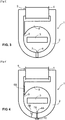
- the figure 2 represents a current transformer according to an embodiment of the invention with a device 6 interposed in a section 7 of the magnetic circuit.
- the energy losses in the iron of the magnetic circuit increase in particular when the fundamental frequency of the electric network increases and becomes higher than 100 Hz or when a high frequency current or harmonics of current are superimposed on the load current flowing in the conductor 3 primary.
- the magnetization variation device limits the circulation of the magnetic flux to a value less than 50% of the value at 20 ° C when the temperature is above 150 ° C.
- the magnetization variation device creates an additional total or partial air gap in the magnetic circuit to limit the circulation of the magnetic flux when the temperature exceeds a predetermined threshold.
- the device 6 is a magnetic flux limiter as a function of the temperature. The advantage of such a device is that it does not create an additional air gap at a low current level for which it is necessary to have a good transfer of energy to the secondary winding. In addition, at low current level the heating remains low.
- the figure 3 represents a current transformer according to another embodiment of the invention.
- the magnetic circuit has a partially rounded shape and has a magnetic shunt 8 with an air gap 9.
- the shunt 8 diverts a magnetic flux when the magnetization of the magnetic circuit exceeds a predetermined level so as to reduce the flux in part 5 of the receiving magnetic circuit the secondary winding 4.
- the shunt 8 has the function of limiting the secondary current of the winding 4 when the current in the primary conductor increases.
- the shunt 8 is made in the same sheets as the magnetic circuit 2.
- shunts can be added to the magnetic circuit and made from a different material, in particular iron powder for better regulation of the current in the secondary winding.
- a device 6A for varying the magnetization of a part 7A of said magnetic circuit is held by a holding device 10 for the magnetic circuit. If the device 6A is mechanical, the holding device 10 is also used to ensure the return to the normal position.
- a device 6B for varying the magnetization of a part 7B of said magnetic circuit can also be arranged in the air gap 9 of the shunt 8. In this case, if the device 6B is a mechanical device and if an opening is placed on the part 7B of the magnetic circuit remote from the device 6B, then an opening of greater amplitude is possible on the part 7B to reduce the magnetization of the magnetic circuit 2.
- the variation device 6 magnetization comprises a mechanical device 11 housed in a recess 12 of the magnetic circuit 2 to produce an air gap 13 or increase an air gap by opening the magnetic circuit 2 when the temperature reaches said predetermined threshold.
- said predetermined threshold is between 120 ° C and 180 ° C.
- the mechanical device 11 creates an additional air gap which will increase from a temperature threshold.
- the mechanical device 11 comprises blades 14 of bimetal mounted head to tail and housed in the recess 12 to act on a spacing of the magnetic circuit generating an air gap 13.
- the recess 12 makes it possible to contain the bimetallic strips in position so to produce a thrust perpendicular to their deformation under the action of temperature.
- a device 10 for holding the magnetic circuit includes a return spring to ensure that the magnetic circuit is properly closed or re-closed and to avoid noise.
- the deflection of bimetallic strips spreads the edges of the air gap from a fixed temperature.
- the magnetic circuit is worked in mechanical elasticity so the operation is reversible.
- a gap or air gap of 0.5 mm is sufficient to significantly reduce iron losses by -50% and thus reduce or limit the heating of the magnetic circuit.
- Such a separation of the magnetic circuit has little impact on the secondary current when the primary current is at a nominal operating current.
- said air gap is greater than 0.5 mm when the temperature is greater than 120 ° C.
- the mechanical device comprises a number of 6 to 12 bimetal blades.
- the embodiment of the mechanical limiting device comprises 8 blades of bimetal material mounted head to tail.
- the location of the recess is preferably in the magnetic circuit with separation of a cut section as in the figures.
- the recess can also be placed on an edge or outside of the magnetic circuit or on a support causing separation by air gap.
- the Figures 9 to 11 represent details of the blades composing the device for varying the magnetization according to the first embodiment.
- An example of a bimetal blade is shown on the figure 9 , a first face 16 of the blade consists of a first material having a first coefficient of expansion and a second face 17 consists of a second material having a second coefficient of expansion lower than the first coefficient of expansion.
- the figure 9 shows two blades 15 mounted head to tail or face to face at low temperature for example 20 ° C and the figure 11 shows the same blades in high temperature of the order of 130 ° C.
- the deformation of the blades is intended to push the walls of a section of the magnetic circuit to create an air gap at high temperature.
- the size of each blade has a length of 8.5 mm, a width of 3 mm and a thickness of 0.6 mm.
- the displacement or length is greater than 0.5 mm when the temperature is greater than 120 ° C or the magnetic circuit has a heating of 120 K.
- the displacement is 0.6 mm.
- the displacement with 10 blades will be of the order of 0.74 mm.
- the bimetal material will preferably be chosen with a linear deformation from -20 ° C to 200 ° C. This movement is a theoretical value which does not take into account the pressure of the return spring of the holding device 10. In reality, the movements may be a little shorter depending on the springs.
- the device for varying the magnetization comprises a static device 18 housed in a section of said magnetic circuit.
- the static device 18 is composed of a magnetic material having a Curie point or Curie temperature lower than that of the material of the magnetic circuit.
- the material of the static device 18 preferably has a Curie temperature of between 80 ° C and 200 ° C, for example around 130 ° C.
- the material of the static device is mainly composed of Fer-Nickel (FeNi) or ferrite. Another example of this type of material is "Phytherm from the company Aperam".
- said magnetic circuit includes a cutout which can generate an air gap.
- an element made of magnetic material with a low Curie point (Tc) is inserted in this cutout or opening.
- the magnetization of this material decreases as a function of the temperature until it vanishes for the temperature Tc.
- the material In the temperature range not presenting risks for the sensor, for example below 120 ° C., the material has magnetic properties allowing normal operation of the sensor, by allowing the magnetic flux to pass freely through the opening. In this case, the power supplied by the sensor at low current levels is little affected.
- the material loses its magnetization enough to behave like air. The iron losses and the heating are then reduced as in the first solution with bimetallic strips.
- the figure 12 shows an embodiment of a static device for varying the magnetization 18 comprising cutouts 19 to avoid losses by eddy current.
- cutouts 19 to avoid losses by eddy current.
- the figure 13 shows a magnetization curve 20 of a device for varying the magnetization as a function of the temperature. Around 20 ° C the magnetization is still maximum. Then, when the temperature increases, the magnetization of the material decreases until it becomes almost zero when the Curie point 21 is exceeded.
- the Figures 14 and 15 represent arrangements according to the second embodiment of a device for varying the static magnetization 18 to limit the magnetic flux as a function of the temperature.
- the magnetic circuit has notches or openings to create air gaps at high temperatures.
- the air gap will be complete since an opening 22 takes up the entire section.
- a holding device 10 prevents displacement of the magnetic circuit.
- the air gap is partial with a notch 23 taking only part of the section of the magnetic circuit. So an element 18 in magnetic material with a low Curie point (Tc) is inserted into the notches or openings 22 or 23.
- the distance from the air gap of the openings 22 or 23 is between 0.5 and 1 mm.
- the figure 16 shows a block diagram of a circuit breaker 30 and a protection device 31 comprising a transformer 1 according to an embodiment of the invention.
- the electronic protection device 31 comprises an electronic processing unit 32 connected to at least one current transformer and supplying an electronic signal D in response to protection functions.
- the protection device comprises a current transformer 1 according to an embodiment of the invention with variation in magnetization.
- the transformer 1 has a secondary winding 4 connected to the processing unit 32 to supply a secondary current Is for measurement or electrical supply.
- the protection device comprises a current transformer 1 with a device for varying the magnetization as a function of the temperature for the supply of the processing unit 32 and a current sensor 33 for supplying a current measurement signal Im to the processing unit.
- the electrical circuit breaker 30 comprises at least one main contact 34 for cutting a current Ip in an electrical circuit 35, a mechanism 36 for controlling the opening of said electrical contact 34 and a protection device 31 supplying a control signal D to said control 36.
- This circuit breaker comprises at least one current transformer 1 with a device for varying the magnetization as a function of the temperature for supplying the processing unit 32 of the protection device 31.
Landscapes
- Engineering & Computer Science (AREA)
- Power Engineering (AREA)
- Physics & Mathematics (AREA)
- Electromagnetism (AREA)
- Chemical & Material Sciences (AREA)
- Composite Materials (AREA)
- Transformers For Measuring Instruments (AREA)
- Emergency Protection Circuit Devices (AREA)
- Soft Magnetic Materials (AREA)
- Protection Of Transformers (AREA)
- Regulation Of General Use Transformers (AREA)
Abstract
Description
- L'invention concerne un transformateur de courant comportant :
- un circuit magnétique en matériau magnétique destiné à être placé autour d'un conducteur primaire, et
- un enroulement secondaire enroulé sur une partie dudit circuit magnétique pour fournir un courant secondaire à un circuit de traitement.
- L'invention concerne aussi un dispositif de protection et un disjoncteur comportant un tel transformateur de courant.
- Un transformateur 1 de courant connu est représenté sur la
figure 1 . Il comporte un circuit magnétique 2 destiné à être placé autour d'un conducteur 3 primaire, et un enroulement 4 secondaire enroulé sur une partie 5 dudit circuit magnétique. Le circuit magnétique est souvent réalisé en tôles empilées. Ces tôles sont composées majoritairement en fer et sont prévues pour fonctionner à des fréquences du réseau électrique, notamment en 50 Hz ou 60 Hz. - Lorsque la fréquence fondamentale du réseau électrique augmente et devient supérieure à 100 Hz ou lorsqu'un courant haute fréquence ou des harmoniques de courant sont superposés au courant de charge circulant dans le conducteur 3 primaire, des pertes d'énergie dans le fer du circuit magnétique sont générées. Ces pertes fer induisent un échauffement du circuit magnétique ainsi que des composants attenants ou en contact avec le circuit magnétique. Ces échauffements sont d'autant sensibles lorsque les transformateurs sont intégrés dans des boitiers isolants avec d'autres composants électriques ou électroniques. L'utilisation de boitiers isolants permet de garantir un isolement électrique entre le conducteur primaire 3 et le reste de l'équipement électrique associé au transformateur de courant.
- L'invention a pour but un transformateur de courant capable d'éviter ou réduire des échauffements du circuit magnétique ainsi qu'un dispositif de protection et un disjoncteur comportant un tel transformateur de courant.
- Dans un transformateur de courant comportant un circuit magnétique en matériau magnétique destiné à être placé autour d'un conducteur primaire, et un enroulement secondaire enroulé sur une partie dudit circuit magnétique pour fournir un courant secondaire à un circuit de traitement selon l'invention, le circuit magnétique comprend au moins un dispositif de variation de la magnétisation d'une partie dudit circuit magnétique en fonction de la température pour limiter ou réduire le flux magnétique dans le circuit magnétique lorsque la température du circuit magnétique augmente.
- De préférence, le dispositif de variation de la magnétisation limite la circulation du flux magnétique à une valeur inférieure à 50% de la valeur à 20°C lorsque la température est supérieure à 150°C.
- Avantageusement, le dispositif de variation de la magnétisation crée un entrefer supplémentaire total ou partiel dans le circuit magnétique pour limiter la circulation du flux magnétique lorsque la température devient supérieure à un seuil prédéterminé. De préférence, ledit seuil prédéterminé est compris entre 120°C et 180°C.
- Selon un premier mode de réalisation de l'invention préférentiel, le dispositif de variation de la magnétisation comprend un dispositif mécanique logé dans un évidement du circuit magnétique pour produire un entrefer ou augmenter un entrefer par ouverture du circuit magnétique lorsque la température atteint ledit seuil prédéterminé.
- Avantageusement, le dispositif mécanique comporte des lames de bimétal montées tête-bêche logé dans un évidement qui agit sur un écartement du circuit magnétique générant un entrefer.
- De préférence, le dispositif mécanique comporte un nombre de 6 à 12 lames de bimétal.
- Avantageusement, ledit entrefer est supérieur à 0,5 mm lorsque la température est supérieure à 120°C ou le circuit magnétique a un échauffement de 120 K.
- Selon un second mode de réalisation de l'invention préférentiel, le dispositif de variation de la magnétisation comprend un dispositif statique logé dans une section dudit circuit magnétique, ledit dispositif statique étant composé d'un matériau magnétique ayant un point de Curie ou température de Curie plus basse que celle du matériau magnétique du circuit magnétique.
- De préférence, le matériau du dispositif statique a une température de Curie comprise entre 80°C et 200°C.
- Avantageusement, le matériau du dispositif statique est composé majoritairement de fer Nickel ou de ferrite.
- De préférence, le matériau du dispositif statique comporte des découpes pour éviter les courants pertes par courants de Foucault.
- Un dispositif de protection électronique selon l'invention comportant une unité de traitement électronique connectée à au moins un transformateur de courant et fournissant un signal électronique en réponse à des fonctions de protection comporte un transformateur de courant tel que défini ci-dessus ayant un enroulement secondaire connecté à ladite unité de traitement pour fournir un courant secondaire de mesure ou d'alimentation électrique.
- Un disjoncteur électrique selon l'invention comportant au moins un contact électrique principal pour couper un courant dans un circuit électrique, un mécanisme de commande de l'ouverture dudit contact électrique et un dispositif de protection fournissant un signal de commande audit mécanisme de commande comporte au moins un transformateur de courant tel que défini ci-dessus connecté à une unité de traitement dudit dispositif de protection.
- D'autres avantages et caractéristiques ressortiront plus clairement de la description qui va suivre, de modes particuliers de réalisation de l'invention, donnés à titre d'exemples non limitatifs, et représentés aux dessins annexés sur lesquels :
- [
Fig 1 ] - lafigure 1 représente un transformateur de courant de l'art antérieur ; - [
Fig 2 ] - lafigure 2 représente un transformateur de courant selon un premier mode de réalisation de l'invention ; - [
Fig 3 ] - lafigure 3 représente un transformateur de courant selon un second mode de réalisation de l'invention ; - [
Fig 4 ] - lafigure 4 représente un transformateur de courant selon un troisième mode de réalisation de l'invention ; - [
Fig 5-8 ] - lesfigures 5 à 8 représentent des dispositions d'un premier mode de réalisation mécanique d'un dispositif de variation de la magnétisation ; - [
Fig 9-12 ] - lesfigures 9 à 11 représentent des détails de lames composant le dispositif de variation de la magnétisation selon le premier mode de réalisation ; - [
Fig 9-12 ] - lafigure 12 représente un second mode de réalisation statique d'un dispositif de variation de la magnétisation ; - [
Fig 13 ] - lafigure 13 montre une courbe de magnétisation d'un dispositif de variation de la magnétisation en fonction de la température ; - [
Fig 14-15 ] - lesfigures 14 et 15 représentent des dispositions d'un second mode de réalisation d'un dispositif de variation de la magnétisation statique ; et - [
Fig 16 ] - lafigure 16 représente un schéma bloc d'un disjoncteur et d'un dispositif de protection comportant un transformateur selon un mode de réalisation de l'invention. - La
figure 1 représente un transformateur 1 de courant comportant un circuit magnétique 2 en matériau magnétique destiné à être placé autour d'un conducteur primaire 3, et un enroulement secondaire 4 enroulé sur une partie 5 du circuit magnétique 2 pour fournir un courant secondaire à des circuits de traitement. Le circuit magnétique comporte des tôles composées majoritairement en fer est sont prévues pour fonctionner à des fréquences du réseau électrique notamment en 50 Hz ou 60 Hz. - Pour éviter un échauffement du circuit magnétique lorsque des pertes d'énergie dans le fer du circuit magnétique augmentent, le circuit magnétique comprend au moins un dispositif 6 de variation de la magnétisation d'une partie 7 dudit circuit magnétique pour limiter ou réduire le flux magnétique dans le circuit magnétique lorsque la température du circuit magnétique augmente. La
figure 2 représente un transformateur de courant selon un mode de réalisation de l'invention avec un dispositif 6 intercalé dans une section 7 du circuit magnétique. - Les pertes d'énergie dans le fer du circuit magnétique augmentent notamment lorsque la fréquence fondamentale du réseau électrique augmente et devient supérieure à 100 Hz ou lorsqu'un courant haute fréquence ou des harmoniques de courant sont superposés au courant de charge circulant dans le conducteur 3 primaire.
- Par exemple, le dispositif de variation de la magnétisation limite la circulation du flux magnétique à une valeur inférieure à 50% de la valeur à 20°C lorsque la température est supérieure à 150°C. Dans un mode de réalisation préférentiel, le dispositif de variation de la magnétisation crée un entrefer supplémentaire total ou partiel dans le circuit magnétique pour limiter la circulation du flux magnétique lorsque la température devient supérieure à un seuil prédéterminé. Ainsi, le dispositif 6 est un limiteur de flux magnétique en fonction de la température. L'avantage d'un tel dispositif est de ne pas créer d'entrefer supplémentaire à bas niveau de courant pour lequel il est nécessaire d'avoir un bon transfert d'énergie vers l'enroulement secondaire. De plus, à bas niveau de courant l'échauffement reste faible.
- La
figure 3 représente un transformateur de courant selon un autre mode de réalisation de l'invention. Le circuit magnétique a une forme en partie arrondie et comporte un shunt magnétique 8 à entrefer 9. Le shunt 8 détourne un flux magnétique lorsque la magnétisation du circuit magnétique dépasse un niveau prédéterminé de manière à réduire le flux dans la partie 5 du circuit magnétique recevant l'enroulement secondaire 4. Le shunt 8 a pour fonction de limiter le courant secondaire de l'enroulement 4 lorsque le courant dans le conducteur primaire augmente. Dans le mode de réalisation de lafigure 3 , le shunt 8 est réalisé dans les mêmes tôles que le circuit magnétique 2. Cependant, d'autres modes de réalisation sont possibles. Par exemple, des shunts peuvent être rapportés sur le circuit magnétique et réalisés dans un matériau différent, notamment en poudre de fer pour une meilleure régulation du courant dans l'enroulement secondaire. - Un autre mode de réalisation d'un transformateur de courant selon l'invention est représenté sur la
figure 4 . Un dispositif 6A de variation de la magnétisation d'une partie 7A dudit circuit magnétique est maintenu par un dispositif de maintien 10 du circuit magnétique. Si le dispositif 6A est mécanique, le dispositif 10 de maintien est aussi utilisé pour assurer le rappel en position normale. Un dispositif 6B de variation de la magnétisation d'une partie 7B dudit circuit magnétique peut aussi être disposé dans l'entrefer 9 du shunt 8. Dans ce cas, si le dispositif 6B est un dispositif mécanique et si une ouverture est placée sur la partie 7B du circuit magnétique éloignée du dispositif 6B, alors une ouverture de plus grande amplitude est possible sur la partie 7B pour réduire la magnétisation du circuit magnétique 2. - Selon un premier mode de réalisation du dispositif limiteur de flux magnétique en fonction de la température représenté sur les
figures 5 à 8 , le dispositif 6 de variation de la magnétisation comprend un dispositif mécanique 11 logé dans un évidement 12 du circuit magnétique 2 pour produire un entrefer 13 ou augmenter un entrefer par ouverture du circuit magnétique 2 lorsque la température atteint ledit seuil prédéterminé. De préférence, ledit seuil prédéterminé est compris entre 120°C et 180°C. - Le dispositif mécanique 11 crée un entrefer supplémentaire qui va augmenter à partir d'un seuil de température. Pour cela, Le dispositif mécanique 11 comporte des lames 14 de bimétal montées tête-bêche et logées dans l'évidement 12 pour agir sur un écartement du circuit magnétique générant un entrefer 13. L'évidement 12 permet de contenir les bilames en position de manière à produire une poussée perpendiculairement à leur déformation sous l'action de la température. Un dispositif de maintien 10 du circuit magnétique comporte un ressort de rappel pour assurer une bonne fermeture du circuit magnétique ou la re-fermeture et éviter le bruit.
- Ainsi, La déflexion des bilames écarte les bords de l'entrefer à partir d'une température fixée. Dans ce cas, On travaille le circuit magnétique en élasticité mécanique donc le fonctionnement est réversible. Un écartement ou un entrefer de 0,5 mm est suffisant pour réduire significativement les pertes fer de -50% et de réduire ou limiter ainsi l'échauffement du circuit magnétique. Un tel écartement du circuit magnétique a peu d'impact sur le courant secondaire lorsque le courant primaire est à un courant nominal de fonctionnement. Avantageusement, ledit entrefer est supérieur à 0,5 mm lorsque la température est supérieure à 120°C.
- De préférence, le dispositif mécanique comporte un nombre de 6 à 12 lames de bimétal. Sur les
figures 5 à 8 le mode de réalisation du dispositif limiteur mécanique comporte 8 lames de matériau bimétal montées tête-bêche. - L'emplacement de l'évidement est de préférence dans le circuit magnétique avec séparation d'une section découpée comme sur les figures. Cependant l'évidement peux aussi être disposé sur un bord ou à l'extérieur du circuit magnétique ou sur un support provoquant la séparation par entrefer.
- Les
figures 9 à 11 représentent des détails de lames composant le dispositif de variation de la magnétisation selon le premier mode de réalisation. Un exemple de lame bimétal est représentée sur lafigure 9 , une première face 16 de la lame est constituée d'un premier matériau ayant un premier coefficient de dilatation et une seconde face 17 est constituée d'un second matériau ayant un second coefficient de dilatation inférieur au premier coefficient de dilatation. Lafigure 9 montre deux lames 15 montées en tête-bêche ou face à face à basse température par exemple 20°C et lafigure 11 montre les mêmes lames en haute température de l'ordre 130 °C. La déformation des lames est destinée à pousser les parois d'une section du circuit magnétique pour créer un entrefer à haute température. Dans un exemple de réalisation, la taille de chaque lame à une longueur 8,5 mm, une largeur 3 mm et épaisseur 0,6 mm. Ainsi, le déplacement ou longueur est supérieur à 0,5 mm lorsque la température est supérieure à 120°C ou le circuit magnétique a un échauffement de 120 K. Pour un ensemble de 8 lames, le déplacement est de 0,6 mm. Le déplacement avec 10 lames sera de l'ordre de 0,74 mm. Le matériau bilame sera choisi de préférence avec une déformation de linéaire de -20 °C à 200°C. Ce déplacement est une valeur théorique qui ne tient pas compte de la pression du ressort de rappel du dispositif de maintien 10. Dans la réalité, les déplacements peuvent un peu moins longs en fonction des ressorts. - Afin d'éviter des mouvements mécaniques du circuit magnétique, dans un second mode de réalisation du dispositif limiteur de flux magnétique en fonction de la température, le dispositif de variation de la magnétisation comprend un dispositif statique 18 logé dans une section dudit circuit magnétique. Selon ce second mode de réalisation de l'invention, le dispositif statique 18 est composé d'un matériau magnétique ayant un point de Curie ou température de Curie plus basse que celle du matériau du circuit magnétique. Le matériau du dispositif statique 18 a de préférence une température de Curie comprise entre 80°C et 200°C, par exemple autour de 130°C. Avantageusement, le matériau du dispositif statique est composé majoritairement de Fer-Nickel (FeNi) ou de ferrite. Un autre exemple de ce type de matériaux est le "Phytherm de la société Aperam".
- Ainsi pour limiter la température du circuit magnétique, ledit circuit magnétique comporte une découpe pouvant générer un entrefer. Dans cette découpe ou ouverture, un élément en matériau magnétique à bas point de Curie (Tc) est inséré. L'aimantation de ce matériau décroit en fonction de la température jusqu'à s'annuler pour la température Tc. Dans la plage de températures ne présentant pas de risques pour le capteur par exemple inférieures à 120 °C, le matériau a des propriétés magnétiques permettant un fonctionnement normal du capteur, en laissant passer librement le flux magnétique à travers l'ouverture. Dans ce cas, la puissance fournie par le capteur aux bas niveaux de courants est peu affectée. A l'approche de la température limite définie, le matériau perd suffisamment son aimantation pour se comporter comme de l'air. Les pertes fer et l'échauffement sont alors réduits comme dans la première solution avec bilames.
- La
figure 12 représente un mode de réalisation d'un dispositif statique de variation de la magnétisation 18 comportant des découpes 19 pour éviter des pertes par courant de Foucault. Lorsque le matériau est de la ferrite des découpes ne sont pas nécessaires puisque le ce matériau n'est pas un bon conducteur ou isolant électrique. - La
figure 13 montre une courbe 20 de magnétisation d'un dispositif de variation de la magnétisation en fonction de la température. Autour de 20 °C la magnétisation est encore maximale. Puis, lorsque la température augmente la magnétisation du matériau diminue jusqu'à devenir quasiment nulle au dépassement du point de Curie 21. - Les
figures 14 et 15 représentent des dispositions selon le second mode de réalisation d'un dispositif de variation de la magnétisation statique 18 pour limiter le flux magnétique en fonction de la température. Le circuit magnétique comporte des entailles ou des ouvertures pour créer des entrefers à des températures élevées. Sur lafigure 14 l'entrefer sera complet puisqu'une ouverture 22 prend toute la section. Dans ce cas, un dispositif 10 de maintien empêche de déplacement du circuit magnétique. Sur lafigure 15 , l'entrefer est partiel avec une entaille 23 ne prenant qu'une partie de la section du circuit magnétique. Ainsi, un élément 18 en matériau magnétique à bas point de Curie (Tc) est inséré dans les entailles ou ouvertures 22 ou 23. De préférence, la distance de l'entrefer des ouvertures 22 ou 23 est comprise entre 0,5 et 1 mm. - La
figure 16 représente un schéma bloc d'un disjoncteur 30 et d'un dispositif 31 de protection comportant un transformateur 1 selon un mode de réalisation de l'invention. - Le dispositif de protection électronique 31 comporte une unité de traitement 32 électronique connectée à au moins un transformateur de courant et fournissant un signal électronique D en réponse à des fonctions de protection. Le dispositif de protection comporte un transformateur de courant 1 selon un mode de réalisation de l'invention a variation de magnétisation. Le transformateur 1 a un enroulement secondaire 4 connecté à l'unité de traitement 32 pour fournir un courant secondaire Is de mesure ou d'alimentation électrique. Dans le cas particulier de la
figure 16 , le dispositif de protection comporte un transformateur de courant 1 avec un dispositif de variation de la magnétisation en fonction de la température pour l'alimentation de l'unité de traitement 32 et un capteur de courant 33 pour fournir un signal de mesure de courant Im à l'unité de traitement. - Le disjoncteur électrique 30 comporte au moins un contact principal 34 pour couper un courant Ip dans un circuit électrique 35, un mécanisme 36 de commande de l'ouverture dudit contact électrique 34 et un dispositif de protection 31 fournissant un signal de commande D audit mécanisme de commande 36. Ce disjoncteur comporte au moins un transformateur de courant 1 avec un dispositif de variation de la magnétisation en fonction de la température pour l'alimentation de l'unité de traitement 32 du dispositif de protection 31. Le conducteur primaire 3, faisant partie du circuit électrique 35, traverse l'intérieur du circuit magnétique 2 du transformateur de courant 1.
Claims (14)
- Transformateur (1) de courant comportant :- un circuit magnétique (2) en matériau magnétique destiné à être placé autour d'un conducteur primaire (3), et- un enroulement secondaire (4) enroulé sur une partie (5) dudit circuit magnétique (2) pour fournir un courant secondaire à un circuit de traitement (32),caractérisé en ce que le circuit magnétique (2) comprend au moins un dispositif (6, 6A, 6B) de variation de la magnétisation d'une partie (7) dudit circuit magnétique en fonction de la température pour limiter ou réduire le flux magnétique dans le circuit magnétique lorsque la température du circuit magnétique augmente.
- Transformateur de courant selon la revendication 1 caractérisé en ce que le dispositif (6, 6A, 6B) de variation de la magnétisation limite la circulation du flux magnétique à une valeur inférieure à 50% de la valeur à 20°C lorsque la température est supérieure à 150°C.
- Transformateur de courant selon l'une des revendications 1 ou 2 caractérisé en ce que le dispositif (6, 6A, 6B) de variation de la magnétisation crée un entrefer supplémentaire total ou partiel dans le circuit magnétique pour limiter la circulation du flux magnétique lorsque la température devient supérieure à un seuil prédéterminé.
- Transformateur de courant selon la revendication 3 caractérisé en ce que ledit seuil prédéterminé est compris entre 120°C et 180°C.
- Transformateur de courant selon l'une quelconque des revendications 1 à 4 caractérisé en ce que le dispositif (6, 6A, 6B) de variation de la magnétisation comprend un dispositif mécanique (11, 14) logé dans un évidement (12) du circuit magnétique (2) pour produire un entrefer (13) ou augmenter un entrefer (13) par ouverture du circuit magnétique (2) lorsque la température atteint ledit seuil prédéterminé.
- Transformateur de courant selon la revendication 5 caractérisé en ce que le dispositif mécanique (11, 14) comporte des lames (15) de bimétal montées tête-bêche logé dans un évidement (12) qui agit sur un écartement du circuit magnétique générant un entrefer.
- Transformateur de courant selon la revendication 6 caractérisé en ce que le dispositif mécanique (11, 14) comporte un nombre de 6 à 12 lames (15) de bimétal (16, 17).
- Transformateur de courant selon l'une des revendications 6 ou 7 caractérisé en ce ledit entrefer (13) est supérieur à 0,5 mm lorsque la température est supérieure à 120°C ou le circuit magnétique a un échauffement de 120 K.
- Transformateur de courant selon l'une quelconque des revendications 1 à 4 caractérisé en ce que le dispositif (6, 6A, 6B) de variation de la magnétisation comprend un dispositif statique (18) logé dans une section dudit circuit magnétique (2), ledit dispositif statique étant composé d'un matériau magnétique ayant un point de Curie ou température de Curie plus basse que celle du matériau magnétique du circuit magnétique (2).
- Transformateur de courant selon la revendication 9 caractérisé en ce que le matériau du dispositif statique (18) a une température de Curie comprise entre 80°C et 200°C.
- Transformateur de courant selon l'une des revendications 9 ou 10 caractérisé en ce que le matériau du dispositif statique (18) est composé majoritairement de fer Nickel (FeNi) ou de ferrite.
- Transformateur de courant selon l'une quelconque des revendications 9 à 11 caractérisé en ce que le matériau du dispositif statique (18) comporte des découpes (19) pour éviter les courants pertes par courants de Foucault.
- Dispositif de protection électronique (31) comportant une unité de traitement (32) électronique connectée à au moins un transformateur de courant (1) et fournissant un signal électronique (D) en réponse à des fonctions de protection, dispositif caractérisé en ce qu'il comporte un transformateur de courant (1) selon l'une des revendications 1 à 12 ayant un enroulement secondaire (4) connecté à ladite unité de traitement (32) pour fournir un courant secondaire de mesure ou d'alimentation électrique (Is).
- Disjoncteur électrique (30) comportant au moins un contact électrique principal (34) pour couper un courant (Ip) dans un circuit électrique (35), un mécanisme de commande (36) de l'ouverture dudit contact électrique (34) et un dispositif de protection (31) fournissant un signal de commande (D) audit mécanisme de commande (36) caractérisée en ce qu'il comporte au moins un transformateur de courant (1) selon l'une quelconque des revendications 1 à 12 connecté à une unité de traitement (32) dudit dispositif de protection (31).
Applications Claiming Priority (1)
| Application Number | Priority Date | Filing Date | Title |
|---|---|---|---|
| FR1872079A FR3089340B1 (fr) | 2018-11-29 | 2018-11-29 | Transformateur de courant, dispositif de protection et disjoncteur électrique comportant un tel transformateur |
Publications (2)
| Publication Number | Publication Date |
|---|---|
| EP3660875A1 true EP3660875A1 (fr) | 2020-06-03 |
| EP3660875B1 EP3660875B1 (fr) | 2021-01-27 |
Family
ID=65951762
Family Applications (1)
| Application Number | Title | Priority Date | Filing Date |
|---|---|---|---|
| EP19207422.7A Active EP3660875B1 (fr) | 2018-11-29 | 2019-11-06 | Transformateur de courant, dispositif de protection et disjoncteur electrique comportant un tel transformateur |
Country Status (7)
| Country | Link |
|---|---|
| US (1) | US11295885B2 (fr) |
| EP (1) | EP3660875B1 (fr) |
| CN (1) | CN111243835B (fr) |
| AU (1) | AU2019268212B2 (fr) |
| BR (1) | BR102019023509B1 (fr) |
| ES (1) | ES2864740T3 (fr) |
| FR (1) | FR3089340B1 (fr) |
Cited By (1)
| Publication number | Priority date | Publication date | Assignee | Title |
|---|---|---|---|---|
| EP3905287A4 (fr) * | 2018-12-26 | 2022-03-09 | Ls Electric Co., Ltd. | Transformateur de courant de disjoncteur à air |
Families Citing this family (2)
| Publication number | Priority date | Publication date | Assignee | Title |
|---|---|---|---|---|
| US11631518B2 (en) * | 2019-08-29 | 2023-04-18 | Ford Global Technologies, Llc | Power inductor with variable width air gap |
| JP7561721B2 (ja) | 2021-09-30 | 2024-10-04 | 三菱電機株式会社 | 変流器一体形電流センサおよび遮断器 |
Citations (4)
| Publication number | Priority date | Publication date | Assignee | Title |
|---|---|---|---|---|
| FR1163942A (fr) * | 1955-11-15 | 1958-10-02 | Western Electric Co | Dispositif inductif ajustable à compensation de température |
| DE2359756A1 (de) * | 1973-11-30 | 1975-06-12 | Siemens Ag | Saettigungswandler |
| FR2725320A1 (fr) * | 1994-09-29 | 1996-04-05 | Schneider Electric Sa | Dispositif de declenchement comportant au moins un transformateur de courant |
| FR2999013A1 (fr) * | 2012-12-03 | 2014-06-06 | Schneider Electric Ind Sas | Dispositif magnetothermique de limitation de courant |
Family Cites Families (11)
| Publication number | Priority date | Publication date | Assignee | Title |
|---|---|---|---|---|
| US1710862A (en) * | 1927-11-21 | 1929-04-30 | Delco Remy Corp | Ignition coil |
| US3662307A (en) * | 1968-12-12 | 1972-05-09 | Matsushita Electric Industrial Co Ltd | Flyback transformer |
| US4068275A (en) * | 1976-06-09 | 1978-01-10 | Westinghouse Electric Corporation | Ground fault protective apparatus and method |
| JP4020177B2 (ja) * | 1998-05-21 | 2007-12-12 | 三菱電機株式会社 | 変成器 |
| JP2009224439A (ja) * | 2008-03-14 | 2009-10-01 | Seiko Epson Corp | 磁気コア及び磁気コアを有するトランス |
| ES1068677Y (es) * | 2008-08-12 | 2009-02-16 | Ion Oil S L | Dispositivo inhibidor estatico de los campos de influencia externa aplicable a fluidos, liquidos, gases y materia organica en general |
| CN103636087B (zh) * | 2011-07-04 | 2016-02-17 | 三菱电机株式会社 | 温度监视装置及温度监视方法 |
| US9631251B2 (en) * | 2012-11-29 | 2017-04-25 | Amp Annealing Limited | Cartridge case induction annealing apparatus |
| DE102013222435B4 (de) * | 2013-11-05 | 2019-06-06 | SUMIDA Components & Modules GmbH | Magnetkernelement, Magnetkernmodul und ein das Magnetkernmodul verwendendes induktives Bauelement |
| CN105679494A (zh) * | 2016-03-15 | 2016-06-15 | 东莞铭普光磁股份有限公司 | 一种可调电感器 |
| CN206921628U (zh) * | 2017-04-27 | 2018-01-23 | 安徽中富磁电有限公司 | 一种新型高频变压器用铁氧体磁芯 |
-
2018
- 2018-11-29 FR FR1872079A patent/FR3089340B1/fr not_active Expired - Fee Related
-
2019
- 2019-11-06 ES ES19207422T patent/ES2864740T3/es active Active
- 2019-11-06 EP EP19207422.7A patent/EP3660875B1/fr active Active
- 2019-11-08 BR BR102019023509-8A patent/BR102019023509B1/pt active IP Right Grant
- 2019-11-15 US US16/684,928 patent/US11295885B2/en active Active
- 2019-11-22 AU AU2019268212A patent/AU2019268212B2/en active Active
- 2019-11-25 CN CN201911166535.5A patent/CN111243835B/zh active Active
Patent Citations (4)
| Publication number | Priority date | Publication date | Assignee | Title |
|---|---|---|---|---|
| FR1163942A (fr) * | 1955-11-15 | 1958-10-02 | Western Electric Co | Dispositif inductif ajustable à compensation de température |
| DE2359756A1 (de) * | 1973-11-30 | 1975-06-12 | Siemens Ag | Saettigungswandler |
| FR2725320A1 (fr) * | 1994-09-29 | 1996-04-05 | Schneider Electric Sa | Dispositif de declenchement comportant au moins un transformateur de courant |
| FR2999013A1 (fr) * | 2012-12-03 | 2014-06-06 | Schneider Electric Ind Sas | Dispositif magnetothermique de limitation de courant |
Cited By (2)
| Publication number | Priority date | Publication date | Assignee | Title |
|---|---|---|---|---|
| EP3905287A4 (fr) * | 2018-12-26 | 2022-03-09 | Ls Electric Co., Ltd. | Transformateur de courant de disjoncteur à air |
| US11810709B2 (en) | 2018-12-26 | 2023-11-07 | Ls Electric Co., Ltd. | Current transformer of air circuit breaker |
Also Published As
| Publication number | Publication date |
|---|---|
| CN111243835B (zh) | 2024-12-13 |
| AU2019268212A1 (en) | 2020-06-18 |
| BR102019023509A2 (pt) | 2020-06-09 |
| FR3089340A1 (fr) | 2020-06-05 |
| CN111243835A (zh) | 2020-06-05 |
| BR102019023509B1 (pt) | 2022-11-01 |
| US11295885B2 (en) | 2022-04-05 |
| US20200176166A1 (en) | 2020-06-04 |
| AU2019268212B2 (en) | 2023-02-23 |
| EP3660875B1 (fr) | 2021-01-27 |
| ES2864740T3 (es) | 2021-10-14 |
| FR3089340B1 (fr) | 2020-10-30 |
Similar Documents
| Publication | Publication Date | Title |
|---|---|---|
| EP3660875B1 (fr) | Transformateur de courant, dispositif de protection et disjoncteur electrique comportant un tel transformateur | |
| US8378778B2 (en) | Varistor comprising an electrode having a protruding portion forming a pole and protection device comprising such a varistor | |
| EP0704867B1 (fr) | Dispositif de déclenchement comportant au moins un transformateur de courant | |
| KR101389709B1 (ko) | 과전류 차단 및 서지 흡수 기능을 갖는 복합 방호부품 | |
| US20120086539A1 (en) | Device for protection from overvoltages with split thermal disconnectors | |
| US7697252B2 (en) | Overvoltage device with enhanced surge suppression | |
| KR20160029082A (ko) | 보호 디바이스 | |
| FR3023988A3 (fr) | ||
| US8477468B2 (en) | Circuit protection device | |
| EP4248534A1 (fr) | Appareillage de protection à coupure électronique | |
| CZ42298A3 (cs) | Oddělovací zařízení pro svodič přepětí | |
| US20130265687A1 (en) | Circuit protection device | |
| FR2897231A1 (fr) | Circuit de protection thermique pour un composant semiconducteur | |
| JP5295635B2 (ja) | サージ防護装置 | |
| US9378916B2 (en) | Heater apparatus, circuit interrupter, and related method | |
| US10741350B2 (en) | Electrical protection unit including a current limiter device | |
| JP6876034B2 (ja) | クリティカル動作状態時に、スイッチギアまたはバックアップヒューズから独立して、電源から過電圧保護デバイスを安全に取り外すための構成 | |
| EP3185275B1 (fr) | Dispositif d'assemblage d'un bilame et d'une pièce formant support de ce bilame et appareil de protection électrique le comportant | |
| US2046962A (en) | Circuit protecting system | |
| FR3088475A1 (fr) | Système de détection et de limitation des effets de perte d'isolement d'un transformateur électrique | |
| CN117254440A (zh) | 具有灭弧功能的电涌抑制装置 | |
| JP2014150251A (ja) | 回路保護装置 | |
| EP1111750A1 (fr) | Dispositif de protection de défaut électrique | |
| WO2019231759A1 (fr) | Protection contre les surtensions de circuit de voie | |
| WO2003063188A1 (fr) | Transformateur de classe 2 sans limitation d'energie avec protection a coefficient de temperature positive |
Legal Events
| Date | Code | Title | Description |
|---|---|---|---|
| PUAI | Public reference made under article 153(3) epc to a published international application that has entered the european phase |
Free format text: ORIGINAL CODE: 0009012 |
|
| STAA | Information on the status of an ep patent application or granted ep patent |
Free format text: STATUS: THE APPLICATION HAS BEEN PUBLISHED |
|
| AK | Designated contracting states |
Kind code of ref document: A1 Designated state(s): AL AT BE BG CH CY CZ DE DK EE ES FI FR GB GR HR HU IE IS IT LI LT LU LV MC MK MT NL NO PL PT RO RS SE SI SK SM TR |
|
| AX | Request for extension of the european patent |
Extension state: BA ME |
|
| STAA | Information on the status of an ep patent application or granted ep patent |
Free format text: STATUS: REQUEST FOR EXAMINATION WAS MADE |
|
| 17P | Request for examination filed |
Effective date: 20200622 |
|
| RBV | Designated contracting states (corrected) |
Designated state(s): AL AT BE BG CH CY CZ DE DK EE ES FI FR GB GR HR HU IE IS IT LI LT LU LV MC MK MT NL NO PL PT RO RS SE SI SK SM TR |
|
| GRAP | Despatch of communication of intention to grant a patent |
Free format text: ORIGINAL CODE: EPIDOSNIGR1 |
|
| STAA | Information on the status of an ep patent application or granted ep patent |
Free format text: STATUS: GRANT OF PATENT IS INTENDED |
|
| RIC1 | Information provided on ipc code assigned before grant |
Ipc: H01F 3/10 20060101ALN20201022BHEP Ipc: H01F 3/14 20060101ALI20201022BHEP Ipc: H01F 21/06 20060101ALI20201022BHEP Ipc: H01F 38/30 20060101AFI20201022BHEP Ipc: H01F 27/40 20060101ALN20201022BHEP Ipc: H01F 38/02 20060101ALN20201022BHEP Ipc: H01F 29/10 20060101ALI20201022BHEP |
|
| GRAS | Grant fee paid |
Free format text: ORIGINAL CODE: EPIDOSNIGR3 |
|
| INTG | Intention to grant announced |
Effective date: 20201119 |
|
| RAP1 | Party data changed (applicant data changed or rights of an application transferred) |
Owner name: SCHNEIDER ELECTRIC INDUSTRIES SAS |
|
| RIN1 | Information on inventor provided before grant (corrected) |
Inventor name: SHI, XIAODONG Inventor name: MAS, PATRICK |
|
| GRAA | (expected) grant |
Free format text: ORIGINAL CODE: 0009210 |
|
| STAA | Information on the status of an ep patent application or granted ep patent |
Free format text: STATUS: THE PATENT HAS BEEN GRANTED |
|
| AK | Designated contracting states |
Kind code of ref document: B1 Designated state(s): AL AT BE BG CH CY CZ DE DK EE ES FI FR GB GR HR HU IE IS IT LI LT LU LV MC MK MT NL NO PL PT RO RS SE SI SK SM TR |
|
| REG | Reference to a national code |
Ref country code: GB Ref legal event code: FG4D Free format text: NOT ENGLISH |
|
| REG | Reference to a national code |
Ref country code: CH Ref legal event code: EP |
|
| REG | Reference to a national code |
Ref country code: AT Ref legal event code: REF Ref document number: 1359101 Country of ref document: AT Kind code of ref document: T Effective date: 20210215 |
|
| REG | Reference to a national code |
Ref country code: IE Ref legal event code: FG4D Free format text: LANGUAGE OF EP DOCUMENT: FRENCH |
|
| REG | Reference to a national code |
Ref country code: DE Ref legal event code: R096 Ref document number: 602019002401 Country of ref document: DE |
|
| REG | Reference to a national code |
Ref country code: NL Ref legal event code: MP Effective date: 20210127 |
|
| REG | Reference to a national code |
Ref country code: LT Ref legal event code: MG9D |
|
| REG | Reference to a national code |
Ref country code: AT Ref legal event code: MK05 Ref document number: 1359101 Country of ref document: AT Kind code of ref document: T Effective date: 20210127 |
|
| PG25 | Lapsed in a contracting state [announced via postgrant information from national office to epo] |
Ref country code: HR Free format text: LAPSE BECAUSE OF FAILURE TO SUBMIT A TRANSLATION OF THE DESCRIPTION OR TO PAY THE FEE WITHIN THE PRESCRIBED TIME-LIMIT Effective date: 20210127 Ref country code: BG Free format text: LAPSE BECAUSE OF FAILURE TO SUBMIT A TRANSLATION OF THE DESCRIPTION OR TO PAY THE FEE WITHIN THE PRESCRIBED TIME-LIMIT Effective date: 20210427 Ref country code: FI Free format text: LAPSE BECAUSE OF FAILURE TO SUBMIT A TRANSLATION OF THE DESCRIPTION OR TO PAY THE FEE WITHIN THE PRESCRIBED TIME-LIMIT Effective date: 20210127 Ref country code: GR Free format text: LAPSE BECAUSE OF FAILURE TO SUBMIT A TRANSLATION OF THE DESCRIPTION OR TO PAY THE FEE WITHIN THE PRESCRIBED TIME-LIMIT Effective date: 20210428 Ref country code: LT Free format text: LAPSE BECAUSE OF FAILURE TO SUBMIT A TRANSLATION OF THE DESCRIPTION OR TO PAY THE FEE WITHIN THE PRESCRIBED TIME-LIMIT Effective date: 20210127 Ref country code: PT Free format text: LAPSE BECAUSE OF FAILURE TO SUBMIT A TRANSLATION OF THE DESCRIPTION OR TO PAY THE FEE WITHIN THE PRESCRIBED TIME-LIMIT Effective date: 20210527 Ref country code: NO Free format text: LAPSE BECAUSE OF FAILURE TO SUBMIT A TRANSLATION OF THE DESCRIPTION OR TO PAY THE FEE WITHIN THE PRESCRIBED TIME-LIMIT Effective date: 20210427 |
|
| PG25 | Lapsed in a contracting state [announced via postgrant information from national office to epo] |
Ref country code: PL Free format text: LAPSE BECAUSE OF FAILURE TO SUBMIT A TRANSLATION OF THE DESCRIPTION OR TO PAY THE FEE WITHIN THE PRESCRIBED TIME-LIMIT Effective date: 20210127 Ref country code: LV Free format text: LAPSE BECAUSE OF FAILURE TO SUBMIT A TRANSLATION OF THE DESCRIPTION OR TO PAY THE FEE WITHIN THE PRESCRIBED TIME-LIMIT Effective date: 20210127 Ref country code: AT Free format text: LAPSE BECAUSE OF FAILURE TO SUBMIT A TRANSLATION OF THE DESCRIPTION OR TO PAY THE FEE WITHIN THE PRESCRIBED TIME-LIMIT Effective date: 20210127 Ref country code: RS Free format text: LAPSE BECAUSE OF FAILURE TO SUBMIT A TRANSLATION OF THE DESCRIPTION OR TO PAY THE FEE WITHIN THE PRESCRIBED TIME-LIMIT Effective date: 20210127 Ref country code: SE Free format text: LAPSE BECAUSE OF FAILURE TO SUBMIT A TRANSLATION OF THE DESCRIPTION OR TO PAY THE FEE WITHIN THE PRESCRIBED TIME-LIMIT Effective date: 20210127 |
|
| PG25 | Lapsed in a contracting state [announced via postgrant information from national office to epo] |
Ref country code: IS Free format text: LAPSE BECAUSE OF FAILURE TO SUBMIT A TRANSLATION OF THE DESCRIPTION OR TO PAY THE FEE WITHIN THE PRESCRIBED TIME-LIMIT Effective date: 20210527 |
|
| REG | Reference to a national code |
Ref country code: ES Ref legal event code: FG2A Ref document number: 2864740 Country of ref document: ES Kind code of ref document: T3 Effective date: 20211014 |
|
| REG | Reference to a national code |
Ref country code: DE Ref legal event code: R097 Ref document number: 602019002401 Country of ref document: DE |
|
| PG25 | Lapsed in a contracting state [announced via postgrant information from national office to epo] |
Ref country code: EE Free format text: LAPSE BECAUSE OF FAILURE TO SUBMIT A TRANSLATION OF THE DESCRIPTION OR TO PAY THE FEE WITHIN THE PRESCRIBED TIME-LIMIT Effective date: 20210127 Ref country code: CZ Free format text: LAPSE BECAUSE OF FAILURE TO SUBMIT A TRANSLATION OF THE DESCRIPTION OR TO PAY THE FEE WITHIN THE PRESCRIBED TIME-LIMIT Effective date: 20210127 Ref country code: SM Free format text: LAPSE BECAUSE OF FAILURE TO SUBMIT A TRANSLATION OF THE DESCRIPTION OR TO PAY THE FEE WITHIN THE PRESCRIBED TIME-LIMIT Effective date: 20210127 |
|
| PG25 | Lapsed in a contracting state [announced via postgrant information from national office to epo] |
Ref country code: DK Free format text: LAPSE BECAUSE OF FAILURE TO SUBMIT A TRANSLATION OF THE DESCRIPTION OR TO PAY THE FEE WITHIN THE PRESCRIBED TIME-LIMIT Effective date: 20210127 Ref country code: SK Free format text: LAPSE BECAUSE OF FAILURE TO SUBMIT A TRANSLATION OF THE DESCRIPTION OR TO PAY THE FEE WITHIN THE PRESCRIBED TIME-LIMIT Effective date: 20210127 Ref country code: RO Free format text: LAPSE BECAUSE OF FAILURE TO SUBMIT A TRANSLATION OF THE DESCRIPTION OR TO PAY THE FEE WITHIN THE PRESCRIBED TIME-LIMIT Effective date: 20210127 |
|
| PLBE | No opposition filed within time limit |
Free format text: ORIGINAL CODE: 0009261 |
|
| STAA | Information on the status of an ep patent application or granted ep patent |
Free format text: STATUS: NO OPPOSITION FILED WITHIN TIME LIMIT |
|
| 26N | No opposition filed |
Effective date: 20211028 |
|
| PG25 | Lapsed in a contracting state [announced via postgrant information from national office to epo] |
Ref country code: AL Free format text: LAPSE BECAUSE OF FAILURE TO SUBMIT A TRANSLATION OF THE DESCRIPTION OR TO PAY THE FEE WITHIN THE PRESCRIBED TIME-LIMIT Effective date: 20210127 |
|
| PG25 | Lapsed in a contracting state [announced via postgrant information from national office to epo] |
Ref country code: IS Free format text: LAPSE BECAUSE OF FAILURE TO SUBMIT A TRANSLATION OF THE DESCRIPTION OR TO PAY THE FEE WITHIN THE PRESCRIBED TIME-LIMIT Effective date: 20210527 |
|
| PG25 | Lapsed in a contracting state [announced via postgrant information from national office to epo] |
Ref country code: MC Free format text: LAPSE BECAUSE OF FAILURE TO SUBMIT A TRANSLATION OF THE DESCRIPTION OR TO PAY THE FEE WITHIN THE PRESCRIBED TIME-LIMIT Effective date: 20210127 |
|
| PG25 | Lapsed in a contracting state [announced via postgrant information from national office to epo] |
Ref country code: LU Free format text: LAPSE BECAUSE OF NON-PAYMENT OF DUE FEES Effective date: 20211106 Ref country code: BE Free format text: LAPSE BECAUSE OF NON-PAYMENT OF DUE FEES Effective date: 20211130 |
|
| REG | Reference to a national code |
Ref country code: BE Ref legal event code: MM Effective date: 20211130 |
|
| PG25 | Lapsed in a contracting state [announced via postgrant information from national office to epo] |
Ref country code: IE Free format text: LAPSE BECAUSE OF NON-PAYMENT OF DUE FEES Effective date: 20211106 |
|
| PG25 | Lapsed in a contracting state [announced via postgrant information from national office to epo] |
Ref country code: CY Free format text: LAPSE BECAUSE OF FAILURE TO SUBMIT A TRANSLATION OF THE DESCRIPTION OR TO PAY THE FEE WITHIN THE PRESCRIBED TIME-LIMIT Effective date: 20210127 |
|
| REG | Reference to a national code |
Ref country code: CH Ref legal event code: PL |
|
| PG25 | Lapsed in a contracting state [announced via postgrant information from national office to epo] |
Ref country code: LI Free format text: LAPSE BECAUSE OF NON-PAYMENT OF DUE FEES Effective date: 20221130 Ref country code: HU Free format text: LAPSE BECAUSE OF FAILURE TO SUBMIT A TRANSLATION OF THE DESCRIPTION OR TO PAY THE FEE WITHIN THE PRESCRIBED TIME-LIMIT; INVALID AB INITIO Effective date: 20191106 Ref country code: CH Free format text: LAPSE BECAUSE OF NON-PAYMENT OF DUE FEES Effective date: 20221130 |
|
| PG25 | Lapsed in a contracting state [announced via postgrant information from national office to epo] |
Ref country code: SI Free format text: LAPSE BECAUSE OF FAILURE TO SUBMIT A TRANSLATION OF THE DESCRIPTION OR TO PAY THE FEE WITHIN THE PRESCRIBED TIME-LIMIT Effective date: 20210127 |
|
| PG25 | Lapsed in a contracting state [announced via postgrant information from national office to epo] |
Ref country code: MK Free format text: LAPSE BECAUSE OF FAILURE TO SUBMIT A TRANSLATION OF THE DESCRIPTION OR TO PAY THE FEE WITHIN THE PRESCRIBED TIME-LIMIT Effective date: 20210127 |
|
| PG25 | Lapsed in a contracting state [announced via postgrant information from national office to epo] |
Ref country code: MT Free format text: LAPSE BECAUSE OF FAILURE TO SUBMIT A TRANSLATION OF THE DESCRIPTION OR TO PAY THE FEE WITHIN THE PRESCRIBED TIME-LIMIT Effective date: 20210127 |
|
| PG25 | Lapsed in a contracting state [announced via postgrant information from national office to epo] |
Ref country code: NL Free format text: LAPSE BECAUSE OF FAILURE TO SUBMIT A TRANSLATION OF THE DESCRIPTION OR TO PAY THE FEE WITHIN THE PRESCRIBED TIME-LIMIT Effective date: 20210127 |
|
| PG25 | Lapsed in a contracting state [announced via postgrant information from national office to epo] |
Ref country code: TR Free format text: LAPSE BECAUSE OF FAILURE TO SUBMIT A TRANSLATION OF THE DESCRIPTION OR TO PAY THE FEE WITHIN THE PRESCRIBED TIME-LIMIT Effective date: 20210127 |
|
| PGFP | Annual fee paid to national office [announced via postgrant information from national office to epo] |
Ref country code: DE Payment date: 20251126 Year of fee payment: 7 |
|
| PGFP | Annual fee paid to national office [announced via postgrant information from national office to epo] |
Ref country code: GB Payment date: 20251125 Year of fee payment: 7 |
|
| PGFP | Annual fee paid to national office [announced via postgrant information from national office to epo] |
Ref country code: FR Payment date: 20251124 Year of fee payment: 7 |
|
| PGFP | Annual fee paid to national office [announced via postgrant information from national office to epo] |
Ref country code: ES Payment date: 20260127 Year of fee payment: 7 |
|
| PGFP | Annual fee paid to national office [announced via postgrant information from national office to epo] |
Ref country code: IT Payment date: 20260123 Year of fee payment: 7 |