EP3660680A1 - Redundant system - Google Patents
Redundant system Download PDFInfo
- Publication number
- EP3660680A1 EP3660680A1 EP19207046.4A EP19207046A EP3660680A1 EP 3660680 A1 EP3660680 A1 EP 3660680A1 EP 19207046 A EP19207046 A EP 19207046A EP 3660680 A1 EP3660680 A1 EP 3660680A1
- Authority
- EP
- European Patent Office
- Prior art keywords
- devices
- communication
- redundant system
- group
- malfunction
- Prior art date
- Legal status (The legal status is an assumption and is not a legal conclusion. Google has not performed a legal analysis and makes no representation as to the accuracy of the status listed.)
- Granted
Links
Images



Classifications
-
- H—ELECTRICITY
- H04—ELECTRIC COMMUNICATION TECHNIQUE
- H04L—TRANSMISSION OF DIGITAL INFORMATION, e.g. TELEGRAPHIC COMMUNICATION
- H04L41/00—Arrangements for maintenance, administration or management of data switching networks, e.g. of packet switching networks
- H04L41/06—Management of faults, events, alarms or notifications
- H04L41/0654—Management of faults, events, alarms or notifications using network fault recovery
-
- G—PHYSICS
- G06—COMPUTING OR CALCULATING; COUNTING
- G06F—ELECTRIC DIGITAL DATA PROCESSING
- G06F11/00—Error detection; Error correction; Monitoring
- G06F11/07—Responding to the occurrence of a fault, e.g. fault tolerance
- G06F11/16—Error detection or correction of the data by redundancy in hardware
- G06F11/20—Error detection or correction of the data by redundancy in hardware using active fault-masking, e.g. by switching out faulty elements or by switching in spare elements
- G06F11/2002—Error detection or correction of the data by redundancy in hardware using active fault-masking, e.g. by switching out faulty elements or by switching in spare elements where interconnections or communication control functionality are redundant
- G06F11/2007—Error detection or correction of the data by redundancy in hardware using active fault-masking, e.g. by switching out faulty elements or by switching in spare elements where interconnections or communication control functionality are redundant using redundant communication media
-
- G—PHYSICS
- G06—COMPUTING OR CALCULATING; COUNTING
- G06F—ELECTRIC DIGITAL DATA PROCESSING
- G06F11/00—Error detection; Error correction; Monitoring
- G06F11/07—Responding to the occurrence of a fault, e.g. fault tolerance
- G06F11/16—Error detection or correction of the data by redundancy in hardware
- G06F11/1658—Data re-synchronization of a redundant component, or initial sync of replacement, additional or spare unit
-
- G—PHYSICS
- G06—COMPUTING OR CALCULATING; COUNTING
- G06F—ELECTRIC DIGITAL DATA PROCESSING
- G06F11/00—Error detection; Error correction; Monitoring
- G06F11/07—Responding to the occurrence of a fault, e.g. fault tolerance
- G06F11/16—Error detection or correction of the data by redundancy in hardware
- G06F11/20—Error detection or correction of the data by redundancy in hardware using active fault-masking, e.g. by switching out faulty elements or by switching in spare elements
- G06F11/2002—Error detection or correction of the data by redundancy in hardware using active fault-masking, e.g. by switching out faulty elements or by switching in spare elements where interconnections or communication control functionality are redundant
- G06F11/2012—Error detection or correction of the data by redundancy in hardware using active fault-masking, e.g. by switching out faulty elements or by switching in spare elements where interconnections or communication control functionality are redundant and using different communication protocols
-
- H—ELECTRICITY
- H04—ELECTRIC COMMUNICATION TECHNIQUE
- H04L—TRANSMISSION OF DIGITAL INFORMATION, e.g. TELEGRAPHIC COMMUNICATION
- H04L45/00—Routing or path finding of packets in data switching networks
- H04L45/28—Routing or path finding of packets in data switching networks using route fault recovery
-
- G—PHYSICS
- G06—COMPUTING OR CALCULATING; COUNTING
- G06F—ELECTRIC DIGITAL DATA PROCESSING
- G06F11/00—Error detection; Error correction; Monitoring
- G06F11/07—Responding to the occurrence of a fault, e.g. fault tolerance
- G06F11/16—Error detection or correction of the data by redundancy in hardware
- G06F11/20—Error detection or correction of the data by redundancy in hardware using active fault-masking, e.g. by switching out faulty elements or by switching in spare elements
- G06F11/202—Error detection or correction of the data by redundancy in hardware using active fault-masking, e.g. by switching out faulty elements or by switching in spare elements where processing functionality is redundant
- G06F11/2023—Failover techniques
- G06F11/203—Failover techniques using migration
-
- G—PHYSICS
- G06—COMPUTING OR CALCULATING; COUNTING
- G06F—ELECTRIC DIGITAL DATA PROCESSING
- G06F11/00—Error detection; Error correction; Monitoring
- G06F11/07—Responding to the occurrence of a fault, e.g. fault tolerance
- G06F11/16—Error detection or correction of the data by redundancy in hardware
- G06F11/20—Error detection or correction of the data by redundancy in hardware using active fault-masking, e.g. by switching out faulty elements or by switching in spare elements
- G06F11/202—Error detection or correction of the data by redundancy in hardware using active fault-masking, e.g. by switching out faulty elements or by switching in spare elements where processing functionality is redundant
- G06F11/2035—Error detection or correction of the data by redundancy in hardware using active fault-masking, e.g. by switching out faulty elements or by switching in spare elements where processing functionality is redundant without idle spare hardware
Definitions
- the disclosure relates to a redundant system and, more particularly, to a redundant system including multiple devices mounted in an aircraft.
- multiple devices 101 A to 101 E may be communicably coupled via a bus 102 that is a communication path to constitute a system 100 as illustrated in, for example, FIG. 7 .
- a malfunction such as a wire break occurs in the bus 102
- communication between the devices is interrupted in a malfunction part, indicated by the sign "x", of the bus 102 and the system 100 is divided into two groups.
- one group includes the devices 101A to 101C, and the other group includes the devices 101D and 101E.
- the system may be constructed so that each of the devices is communicably coupled to two or more of the devices other than the each of the devices via communication paths (see, for example, Japanese Unexamined Patent Application Publication JP H8-265 319 A ).
- each of six devices 201A to 201F such as computers may be communicably coupled to two or more of the devices other than the each of the six devices 201A to 201F via communication paths 202 to construct a system 200.
- this configuration may be expressed by the phrase that "multiple devices are communicably coupled in a ring shape via communication paths", for the purpose of simplifying the description.
- the multiple devices 201A to 201F are kept communicably coupled to each other via the communication paths 202.
- the multiple devices 201A to 201F are not divided into two groups unlike the system 100 (see FIG. 7 ), and communication may be continued among the devices 201A to 201F via the communication paths 202.
- the system 200 is configured such that the multiple devices 201A to 201F are communicably coupled in a ring shape via the communication paths 202, which provides the redundancy of the system 200.
- redundant system a system having the redundancy as described above will be referred to as a "redundant system”.
- An aspect of the invention provides a redundant system including multiple devices communicably coupled via communication paths.
- Each of the devices is communicably coupled via two or more of the communication paths to two or more of the devices other than each of the devices.
- Each of the devices is configured to perform wired communication via two or more of the communication paths with the devices communicably coupled to each of the devices via the two or more of the communication paths in a normal state.
- Each of the devices includes a wireless communication unit.
- each of the devices When each of the devices communicates with two or more of the devices other than each of the devices under a condition that a malfunction occurs in two or more parts in the redundant system, then each of the devices performs a wired communication via the communication path with a counterpart device with which the wired communication via the communication path is enabled, and switches from the wired communication via the communication path to a wireless communication and continues communication with a counterpart device with which the wired communication via the communication path is disabled.
- the redundant system 200 is divided into two groups.
- one group includes devices 201A to 201D, and the other group includes devices 201E and 201F.
- the redundant system 200 is also divided into two groups.
- one group includes the devices 201A to 201C, and the other group includes the devices 201E and 201F.
- a device of a certain group may be unable to communicate with any device of a group(s) other than the certain group.
- the system may be divided into multiple groups, and a device of a certain group may be unable to communicate with any device of a group(s) other than the certain group.
- this configuration may be expressed by the phrase that the multiple devices are communicably coupled in a ring shape via the communication paths, for the purpose of simplifying the description. It is appreciated that this does not limit an actual redundant system to one having a ring shape without a twist.
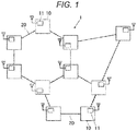
- FIG. 1 illustrates an example of the configuration of the redundant system according to the embodiment.
- a redundant system 1 according to the embodiment includes multiple devices 10 communicably coupled via communication paths 20 such as signal lines. Each of the devices 10 is communicably coupled via the communication paths 20 to two or more of the devices 10 other than the each of the devices 10. That is, the redundant system 1 according to the embodiment includes the multiple devices 10 communicably coupled in the ring shape via the communication paths 20.
- the redundant system 1 in FIG. 1 includes the multiple devices 10 communicably coupled in multiple ring shapes in a combined manner via the communication paths 20.
- the redundant system 1 may include the multiple devices 10 communicably coupled in a single ring shape via the communication paths 20, for example, like the redundant system 200 illustrated in FIG. 8 .
- the redundant system 1 when the redundant system 1 is configured such that all or many of the devices 10 in the aircraft are communicably coupled to each other via the communication paths 20 or the devices 10 physically distant from each other are communicably coupled to each other via the communication paths 20, the volume of the hardware of the redundant system 1 may increase or the number of the communication paths 20 may increase, which may result in an increase in the weight of the aircraft.
- the redundant system 1 when the redundant system 1 is configured such that the devices 10 physically close to each other are communicably coupled to each other via the communication paths 20, the redundant system 1 can avoid the increase in the weight of the aircraft.
- the devices 10 physically close to each other are communicably coupled to each other in a single ring shape via the communication paths 20 in a combined manner via the communication paths 20 as illustrated in FIG. 1 , which provides the redundancy.
- the devices 10 are, for example, computers and modules mounted in an aircraft.
- the devices 10 uniquely perform processes such as control of equipment and appliances of a power system, a steering system, a power supply system, and a communication system.
- the devices 10 constituting the redundant system 1 do not include an alternative device that performs no work in a normal state, that is, a state in which no malfunction occurs in the communication paths 20 , and each of the devices 10 performs a unique process.
- the devices 10 of the redundant system 1 may include an alternative device that performs no process in the normal state.
- each of the devices 10 performs wired communication via the communication paths 20 with the devices 10 (referred to below as the adjacent devices 10) communicably coupled to the each of the device 10 via the communication paths 20.
- each of the devices 10 communicates with the adjacent devices 10 periodically or at predetermined timings (for example, at a timing when transmitting or receiving a signal or data) to confirm that wired communication with the adjacent devices 10 via the communication paths 20 is established, that is, communicable coupling via the communication paths 20 is maintained and no malfunction occurs in the communication paths 20.
- the device 10 when the device 10 becomes unable to perform the wired communication with any of the adjacent devices 10 via the communication path 20 due to, for example, occurrence of a malfunction (such as a wire break that disables the wired communication via the communication paths 20) in the communication path 20, the device 10 notifies all the devices 10 of the redundant system 1 by transmitting a signal indicating that the wired communication is disabled, using the wired communication via the communication paths 20 other than the communication path 20 through which the wired communication is disabled.
- a malfunction such as a wire break that disables the wired communication via the communication paths 20
- each of the devices 10 Upon receipt of the signal, each of the devices 10 recognizes that wired communication between a certain pair of the devices 10 via the communication path 20 is disabled (that is, a malfunction has occurred in the communication path 20 therebetween).
- the multiple devices 10 of the redundant system 1 are kept communicably coupled to each other via the communication paths 20 in the redundant system 1 according to the embodiment even when a malfunction occurs in one of the communication paths 20. Therefore, the wired communication between the devices 10 via the communication paths 20 continues.
- a malfunction may occur in two or more parts in the redundant system 1. For example, a malfunction occurs in one part in the redundant system 1, and then a malfunction occurs in another part in the redundant system 1. Or, a malfunction occurs in two or more parts in the redundant system 1 at the same time. In this case, even in the redundant system 1 according to the embodiment, the wired communication via the communication paths 20 is interrupted in the parts in which a malfunction has occurred.
- each of the devices 10 includes a wireless communication unit 11.
- each of the multiple devices 10 of the redundant system 1 (i) performs the wired communication via the communication path 20 with a counterpart device 10 with which wired communication via the communication path 20 is enabled and (ii) switches from the wired communication via the communication path 20 to wireless communication and continues communication with a counterpart device 10 with which the wired communication via the communication path 20 is disabled.
- a malfunction includes either one or both of a malfunction in the communication path 20 and a malfunction in the device 10. Description will be made on the case in which a malfunction occurs in two communication paths 20 of the redundant system 1, to show a method for continuing communication between the devices 10 even when a malfunction occurs in the redundant system 1 according to the embodiment.
- the redundant system 1 keeps all the devices 10 communicably coupled via the communication paths 20.
- the redundant system 1 continues to function as a single system.
- the redundant system 200 is formed in a single ring via the communication paths 202 like the redundant system 200 illustrated in FIG. 8 , if a malfunction occurs in two of the communication paths of the redundant system 200, the redundant system 200 is divided into two groups (specifically, a group including the devices 201A to 201D and a group including the devices 201E and 201F) as illustrated in FIG. 9A , and the redundant system 200 no longer continues to function as a single system.
- the redundant system 1 is configured such that the multiple devices 10 are communicably coupled in multiple ring shapes in a combined manner via the communication paths 20 as illustrated in FIG. 1 , even if a malfunction occurs in two of the communication paths 20, all the devices 10 is kept communicably coupled via the communication paths 20, and the redundant system 1 continues to function as a single system as described above.
- the device 10A and the device 10J transmit signals (referred to below as "communication outage signals") indicating that the wired communication with the corresponding devices 10J and 10A via the communication paths 20 is disabled, via the communication paths 20 other than the communication paths 20 through which the wired communication is disabled, using the wired communication.
- all the devices 10 in the redundant system 1 are communicably coupled via the communication paths 20.
- Each of the devices 10 receives both the communication outage signal transmitted from the device 10A and the communication outage signal transmitted from the device 10J.
- each of the devices 10 upon receipt of the communication outage signals from these two devices 10, each of the devices 10 recognizes that a malfunction has occurred in the communication paths 20 through which the two devices 10 are communicably coupled and that all the devices 10 are kept communicably coupled via the communication paths 20 (that is, the redundant system 1 continues to function as a single system) even when the malfunction has occurred.
- each of the devices 10 notifies a user of the occurrence of a malfunction, prompts the user for repair, and continues wired communication via the communication paths 20 with the devices 10.
- the devices 10 of a group G1 (see FIG. 4B ) including the devices 10A and 10C can perform wired communication with each other via the communication paths 20, and the devices 10 of a group G2 including the devices 10B and 10D can perform wired communication with each other via the communication paths 20.
- disabled is wired communication between the groups G1 and G2 via the communication paths 20.
- the redundant system 1 is divided into two groups, that is, the groups G1 and G2.
- the device 10B becomes unable to perform wired communication with any devices 10 other than the device 10B via the communication paths 20.
- the one device 10 becomes unable to perform wired communication with any devices 10 other than the device 10B via the communication paths 20.
- the one device 10 is treated as a group, that is, a group G4 consisting of the device 10B that is unable to perform wired communication with any devices 10 other than the device 10B via the communication paths 20.
- multiple devices 10 capable of performing wired communication with each other via the communication paths 20 are treated as a group, and one device 10 that is unable to perform wired communication with the device 10 other than the one device 10 via the communication paths 20 is treated as a group.
- the devices 10 of the redundant system 1 belong to any of groups. As a result, there may be a group including multiple devices 10 and a group consisting of one device 10.
- wireless communication between a device 10 of one group and a device 10 of a group other than the one group may be referred to as wireless communication between the groups for simplification.
- each group includes multiple devices 10 as illustrated in FIGS. 4A and 4B , below. It is noted that the following description is applicable to an example in which a group consists of one device 10.
- the redundant system 1 illustrated in FIG. 1 may continue to function as a single system as illustrated in FIGS. 3A and 3B , or the redundant system 1 may be divided into two groups G1 and G2 as illustrated in FIGS. 4A and 4B and disabled is wired communication between the groups G1 and G2 via the communication paths 20.
- each of the devices 10 determines whether
- both the communication outage signal transmitted from the device 10A and the communication outage signal transmitted from the device 10J are transmitted to all the devices 10.
- each of the devices 10 determines that all the devices 10 are kept communicably coupled via the communication paths 20 even though a malfunction has occurred (that is, the redundant system 1 continues to function as a single system).
- each of the devices 10 notifies a user of the occurrence of a malfunction, prompts the user for repair, and continues wired communication via the communication paths 20 with the devices 10.
- the communication outage signal from the device 10C is transmitted to the devices 10 of the group G1, but the communication outage signal from the device 10D is not transmitted to the devices 10 of the group G1.
- the communication outage signal from the device 10D is transmitted to the devices 10 of the group G2, but the communication outage signal from the device 10C is not transmitted to the devices 10 of the group G2.
- each of the devices 10 when each of the devices 10 receives the communication outage signal from one device 10 and does not receive the communication outage signal from the other device 10, each of the devices 10 determines that a malfunction has occurred and the redundant system 1 has been divided into the two groups G1 and G2.
- each of the devices 10 recognizes which of the devices 10 is communicable to each of the devices 10 via the communication paths 20, by exchanging information with other devices 10.
- each of the devices 10 of the group G1 including the device 10A recognizes (i) that the group G1 includes the seven devices 10 (including the each of the devices 10) communicable via the communication paths 20 and (ii) which of the ten devices 10 the group G1 includes.
- each of the devices 10 of the group G2 including the device 10B recognizes
- each of the devices 10 When each of the devices 10 communicates with the devices 10 of the group to which each of the devices 10 belongs, each of the devices 10 performs wired communication via the communication paths 20. When each of the devices 10 communicates across groups, each of the devices 10 switches to wireless communication using the wireless communication unit 11 to continue the communication.
- single input and single output (SISO) wireless communication may be performed between one of the devices 10 of the group G1 and one of the devices 10 of the group G2.
- wireless communication has a higher error rate and lower reliability than wired communication via the communication paths 20.
- SISO wireless communication either one of multi input and multi output (MIMO) wireless communication, multi input and single output (MISO) wireless communication, and single input and multi output (SIMO) wireless communication may be performed between the groups G1 and G2.
- MIMO multi input and multi output
- MISO multi input and single output
- SIMO single input and multi output
- all (or one or ones of) the devices 10 of the group G1 Upon receipt of the signal, all (or one or ones of) the devices 10 of the group G1 transmit the received signal to the device 10A via the communication paths 20 using the wired communication.
- the devices 10 of different groups that perform wireless communication, the output of wireless communication, and the like may be improved based on the physical distance between the devices 10 of the different groups, the noise strength of wireless communication, and the radio characteristics.
- the communication strength of wireless communication may become weak if the physical distance between the device 10A and the device 10B is large.
- a large noise may be added to the wireless communication between the devices 10A and 10B.
- the obstacle when an obstacle is present between the device 10A and the device 10B, the obstacle may interfere with the radio waves of wireless communication.
- the radio waves of wireless communication between the device 10A and the device 10B may be amplified by reflection or diffraction by an object, such as a wall, other than the device 10A and the device 10B.
- wireless communication may be improved by determining the devices 10 that perform transmission and reception in wireless communication so as to be improved those conditions and determining the output and the like in wireless communication.
- an improvement process may be performed in one or ones of the devices 10 of the groups G1 and G2 based on situations such as noise and an obstacle and the sensitivity of wireless communication in the devices 10, to determine which of (one or ones of) devices 10 of the groups perform wireless communication and how much output power is used in wireless communication.
- a table may be prepared in advance that defines which (one or ones of) devices 10 of the groups performs wireless communication and how much output power is used in the wireless communication when a malfunction occurs in two communication paths 20 of the redundant system 1, for all combinations of two communication paths 20.
- the reliability of wireless communication is lower than that of wired communication via the communication paths 20.
- the redundant system 1 switches the communication between groups to wireless communication when a malfunction has occurred and the redundant system 1 has been divided into two groups. Since the reliability of wireless communication is lower than that of wired communication via the communication paths 20, such a measure is an emergency measure and is taken until wired communication via the communication paths 20 is recovered.
- the amount of wireless communication is desirably reduced.
- two groups generated due to occurrence of a malfunction is classified into a main group and an isolated group.
- communication between the groups is switched from wired communication via the communication paths 20 to wireless communication, data including signals, information, and parameters (the same applies to the following) is transmitted from the isolated group to the main group using wireless communication, but no data is basically transmitted from the main group to the isolated group.
- the main group may simply transmit the requested data to the isolated group using wireless communication.
- each group may be classified into a main group or an isolated group based on, for example, the number of devices 10 of each group.
- the group G1 includes seven devices 10 and the group G2 includes three devices 10. Then, the group G1 is classified into the main group, and the group G2 is classified into the isolated group.
- a group G3 including the device 10A is classified into the main group, and a group G4 including the device 10B is classified into an isolated group.
- a group G5 including the device 10A is classified into the main group, and a group G6 including the device 10B is classified into the isolated group.
- the redundant system 1 includes a management device that manages the redundant system 1
- the group including this management device may be classified into the main group, and the other group may be classified into the isolated group.
- the method for classification into the main group or the isolated group is determined as appropriate.
- wireless communication from the main group to the isolated group is simply limited to necessary communication, so that the amount of wireless communication in the entire redundant system 1 is reduced while the reliability of the entire redundant system 1 is maintained.
- one of the groups may be classified into the main group based on the number of the devices 10 of the groups and the presence or absence of the management device.
- the groups other than the main group may be classified into isolated groups.
- each of the devices 10 may determine the group to be classified into the main group and the groups to be classified into the isolated groups at the time when a malfunction occurs in two or more communication paths 20 of the redundant system 1.
- a table may be prepared in advance that defines a group to be classified into the main group and groups to be classified into the isolated groups when a malfunction occurs in the redundant system 1, for all combinations of two or more communication paths 20.
- each of the devices 10 may recognize the classification of the groups with reference to the table.
- the redundant system 1 is also divided into two groups G5 and G6.
- the redundant system 1 when a malfunction occurs in two or more parts in the devices 10 and the communication paths 20 of the redundant system 1 in which the devices 10 are communicably coupled in a ring shape via the communication paths 20, the redundant system 1 switches to wireless communication from the wired communication via the communication path 20 between
- the process to be uniquely performed by the device 10C is inherited to a device 10 other than the device 10C.
- each of the devices 10 communicates with the other devices 10, for example, exchanges information, recognizes the devices 10 with which the each of the devices 10 is communicable via the communication paths 20, performs wireless communication between groups, and recognizes which group is the main group. It is noted here that a group may consist of one device 10 as described above.
- each of the devices 10 determines that a malfunction has occurred in a certain device (the device 10C in this example).
- a device 10 of the main group inherits and performs the process originally performed by the device 10C in which a malfunction has occurred.
- Such a configuration allows the devices 10 (or one of the devices 10) of the main group to inherit and perform the process originally performed by the device 10C in which a malfunction has occurred, thereby preventing the process originally performed by the device 10C from being not performed.
- the device 10 of the isolated group does not inherit the process originally performed by the device 10C in which a malfunction has occurred, and performs its own process.
- the devices 10 of the isolated group notify the main group of completion or non-completion of a certain process using wireless communication as well as the number of the devices 10 of the isolated group.
- the management device may store, in advance, programs of all the devices 10 of the redundant system 1.
- the management device may inherit and perform the process based on the programs or may cause one of the devices 10 of the main group to inherit the process by transmitting the programs to be used to the device 10.
- each of the devices 10 may store the programs of all the devices 10 of the redundant system 1 in advance.
- any of the devices 10 of the main group (group G5 in the example of FIGS. 6A and 6B ) stores in advance the programs necessary for the process originally performed by the device 10 in which a malfunction has occurred, the device 10 may inherit and perform the process based on the programs.
- one of the devices 10 of the main group inherits the process originally performed by the device 10C in which a malfunction has occurred as described above, for example, one of the devices 10 of the main group that has enough processing power may inherit the process originally performed by the device 10C in which a malfunction has occurred. Alternatively, multiple devices 10 of the main group may inherit and perform the process in corporation.
- the device 10 communicably coupled to the equipment originally processed by the device 10 in which a malfunction has occurred may inherit the process.
- the device 10 communicably coupled to the equipment originally processed by the device 10 in which a malfunction has occurred is present in the isolated group but is absent in the main group, the device 10 of the isolated group may inherit the process originally processed by device 10 in which a malfunction has occurred.
- a table that contains all assumed cases in which a malfunction occurs in the devices 10 and the communication paths 20 of the redundant system 1 may be prepared and, when a malfunction occurs, the device 10 that inherits the processing originally performed by the device 10 in which a malfunction has occurred may be determined based on the table.
Landscapes
- Engineering & Computer Science (AREA)
- Theoretical Computer Science (AREA)
- Quality & Reliability (AREA)
- Physics & Mathematics (AREA)
- General Engineering & Computer Science (AREA)
- General Physics & Mathematics (AREA)
- Computer Networks & Wireless Communication (AREA)
- Signal Processing (AREA)
- Small-Scale Networks (AREA)
Abstract
Description
- The present application claims priority from Japanese Patent Application No.
2018-220889 filed on November 27, 2018 2019-179204 filed on September 30, 2019 - The disclosure relates to a redundant system and, more particularly, to a redundant system including multiple devices mounted in an aircraft.
- When multiple devices are communicably coupled via a communication path such as a signal line to constitute a system,
multiple devices 101 A to 101 E may be communicably coupled via abus 102 that is a communication path to constitute asystem 100 as illustrated in, for example,FIG. 7 . In this case, however, when a malfunction such as a wire break occurs in thebus 102, communication between the devices is interrupted in a malfunction part, indicated by the sign "x", of thebus 102 and thesystem 100 is divided into two groups. InFIG. 7 , one group includes thedevices 101A to 101C, and the other group includes thedevices - It is noted that a part in which a malfunction has occurred will be indicated by the sign "x" in the following figures.
- To avoid the occurrence of such a state, when multiple devices are communicably coupled via communication paths to construct a system, the system may be constructed so that each of the devices is communicably coupled to two or more of the devices other than the each of the devices via communication paths (see, for example, Japanese Unexamined Patent Application Publication
JP H8-265 319 A - That is, as illustrated in
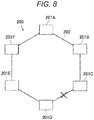
FIG. 8 , for example, each of sixdevices 201A to 201F such as computers may be communicably coupled to two or more of the devices other than the each of the sixdevices 201A to 201F viacommunication paths 202 to construct asystem 200. - When each of multiple devices of a system is communicably coupled to two or more of the devices other than the each of the devices via communication paths as described above, this configuration may be expressed by the phrase that "multiple devices are communicably coupled in a ring shape via communication paths", for the purpose of simplifying the description.
- In such a configuration, even when, for example, a malfunction such as a wire break occurs in the
communication path 202 as illustrated inFIG. 8 , themultiple devices 201A to 201F are kept communicably coupled to each other via thecommunication paths 202. - Accordingly, even when a malfunction occurs in any of the
communication paths 202, themultiple devices 201A to 201F are not divided into two groups unlike the system 100 (seeFIG. 7 ), and communication may be continued among thedevices 201A to 201F via thecommunication paths 202. - As illustrated in
FIG. 8 , thesystem 200 is configured such that themultiple devices 201A to 201F are communicably coupled in a ring shape via thecommunication paths 202, which provides the redundancy of thesystem 200. - In the following description, a system having the redundancy as described above will be referred to as a "redundant system".
- An aspect of the invention provides a redundant system including multiple devices communicably coupled via communication paths. Each of the devices is communicably coupled via two or more of the communication paths to two or more of the devices other than each of the devices. Each of the devices is configured to perform wired communication via two or more of the communication paths with the devices communicably coupled to each of the devices via the two or more of the communication paths in a normal state. Each of the devices includes a wireless communication unit.
- When each of the devices communicates with two or more of the devices other than each of the devices under a condition that a malfunction occurs in two or more parts in the redundant system, then each of the devices performs a wired communication via the communication path with a counterpart device with which the wired communication via the communication path is enabled, and switches from the wired communication via the communication path to a wireless communication and continues communication with a counterpart device with which the wired communication via the communication path is disabled.
-
- FIG. 1
- illustrates an example of the configuration of a redundant system according to an embodiment.
- FIG. 2
- illustrates an example in which a malfunction has occurred in a communication path.
- FIGS. 3A and 3B
- illustrate examples in which all devices are kept communicably coupled via communication paths even when a malfunction has occurred in two communication paths.
- FIGS. 4A and 4B
- illustrate an example in which a malfunction has occurred in two communication paths and the redundant system has been divided into two groups.
- FIG. 5
- illustrates a group consisting of one device that is unable to perform wired communication with any of devices other than the one device.
- FIGS. 6A and 6B
- illustrate an example in which a malfunction has occurred
- in
- a communication path and a device and the redundant system has been divided into two groups.
- FIG. 7
- illustrates an example in which a malfunction has occurred in a bus of a system in which multiple devices are communicably coupled via the bus.
- FIG. 8
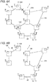
- illustrates an example in which a malfunction has occurred in communication paths of a redundant system in which multiple devices are communicably coupled in a ring shape via the communication paths.
- FIG. 9A
- illustrates a state in which a malfunction has occurred in two communication paths of the redundant system in
FIG. 8 . - FIG. 9B
- illustrates a state in which a malfunction has occurred in a communication path and a device of the redundant system in
FIG. 8 . - Even in a
redundant system 200 in which multiple devices are communicably coupled in a ring shape via communication paths, when a malfunction occurs in two ormore communication paths 202 of theredundant system 200 as illustrated inFIG. 9A , theredundant system 200 is divided into two groups. InFIG. 9A , one group includesdevices 201A to 201D, and the other group includesdevices - In addition, when a malfunction occurs not only in any of the
communication paths 202, but also in any of the devices as illustrated inFIG. 9B (specifically, a malfunction occurs in thecommunication path 202 and thedevice 201D inFIG. 9B ), theredundant system 200 is also divided into two groups. InFIG. 9B , one group includes thedevices 201A to 201C, and the other group includes thedevices - In these cases, a device of a certain group may be unable to communicate with any device of a group(s) other than the certain group.
- As described above, even in the redundant system in which the multiple devices are communicably coupled in a ring shape via the communication paths, when a malfunction occurs in two or more parts, the system may be divided into multiple groups, and a device of a certain group may be unable to communicate with any device of a group(s) other than the certain group.
- It is desirable to provide a redundant system, including multiple devices communicably coupled in a ring shape via communication paths, that allows devices in which a malfunction does not occur to continue communication with each other even when a malfunction occurs in two or more parts in the redundant system.
- A redundant system according to an embodiment of the invention will be described below with reference to the drawings.
- It is assumed that the redundant system is mounted in an aircraft, but the invention is not limited to this example.
- In addition, when each of the multiple devices of the redundant system is communicably coupled to two or more of the devices other than the each of the multiple devices via the communication paths, this configuration may be expressed by the phrase that the multiple devices are communicably coupled in a ring shape via the communication paths, for the purpose of simplifying the description. It is appreciated that this does not limit an actual redundant system to one having a ring shape without a twist.
-
FIG. 1 illustrates an example of the configuration of the redundant system according to the embodiment. - A
redundant system 1 according to the embodiment includesmultiple devices 10 communicably coupled viacommunication paths 20 such as signal lines. Each of thedevices 10 is communicably coupled via thecommunication paths 20 to two or more of thedevices 10 other than the each of thedevices 10. That is, theredundant system 1 according to the embodiment includes themultiple devices 10 communicably coupled in the ring shape via thecommunication paths 20. - The
redundant system 1 inFIG. 1 includes themultiple devices 10 communicably coupled in multiple ring shapes in a combined manner via thecommunication paths 20. Alternatively, theredundant system 1 may include themultiple devices 10 communicably coupled in a single ring shape via thecommunication paths 20, for example, like theredundant system 200 illustrated inFIG. 8 . - In this case, when the
redundant system 1 is configured such that all or many of thedevices 10 in the aircraft are communicably coupled to each other via thecommunication paths 20 or thedevices 10 physically distant from each other are communicably coupled to each other via thecommunication paths 20, the volume of the hardware of theredundant system 1 may increase or the number of thecommunication paths 20 may increase, which may result in an increase in the weight of the aircraft. - However, when the
redundant system 1 is configured such that thedevices 10 physically close to each other are communicably coupled to each other via thecommunication paths 20, theredundant system 1 can avoid the increase in the weight of the aircraft. - In place of the configuration that the
devices 10 physically close to each other are communicably coupled to each other in a single ring shape via thecommunication paths 20, thedevices 10 physically close to each other are communicably coupled in multiple ring shapes in a combined manner via thecommunication paths 20 as illustrated inFIG. 1 , which provides the redundancy. - The
devices 10 are, for example, computers and modules mounted in an aircraft. Thedevices 10 uniquely perform processes such as control of equipment and appliances of a power system, a steering system, a power supply system, and a communication system. - As described above, in the
redundant system 1 according to the embodiment, thedevices 10 constituting theredundant system 1 do not include an alternative device that performs no work in a normal state, that is, a state in which no malfunction occurs in thecommunication paths 20 , and each of thedevices 10 performs a unique process. Alternatively, thedevices 10 of theredundant system 1 may include an alternative device that performs no process in the normal state. - In the normal state, each of the
devices 10 performs wired communication via thecommunication paths 20 with the devices 10 (referred to below as the adjacent devices 10) communicably coupled to the each of thedevice 10 via thecommunication paths 20. - In addition, each of the
devices 10 communicates with theadjacent devices 10 periodically or at predetermined timings (for example, at a timing when transmitting or receiving a signal or data) to confirm that wired communication with theadjacent devices 10 via thecommunication paths 20 is established, that is, communicable coupling via thecommunication paths 20 is maintained and no malfunction occurs in thecommunication paths 20. - In addition, when the
device 10 becomes unable to perform the wired communication with any of theadjacent devices 10 via thecommunication path 20 due to, for example, occurrence of a malfunction (such as a wire break that disables the wired communication via the communication paths 20) in thecommunication path 20, thedevice 10 notifies all thedevices 10 of theredundant system 1 by transmitting a signal indicating that the wired communication is disabled, using the wired communication via thecommunication paths 20 other than thecommunication path 20 through which the wired communication is disabled. - Upon receipt of the signal, each of the
devices 10 recognizes that wired communication between a certain pair of thedevices 10 via thecommunication path 20 is disabled (that is, a malfunction has occurred in thecommunication path 20 therebetween). - As in the redundant system 200 (see
FIG. 8 ) in the related art described above, themultiple devices 10 of theredundant system 1 are kept communicably coupled to each other via thecommunication paths 20 in theredundant system 1 according to the embodiment even when a malfunction occurs in one of thecommunication paths 20. Therefore, the wired communication between thedevices 10 via thecommunication paths 20 continues. - However, a malfunction may occur in two or more parts in the
redundant system 1. For example, a malfunction occurs in one part in theredundant system 1, and then a malfunction occurs in another part in theredundant system 1. Or, a malfunction occurs in two or more parts in theredundant system 1 at the same time. In this case, even in theredundant system 1 according to the embodiment, the wired communication via thecommunication paths 20 is interrupted in the parts in which a malfunction has occurred. - In order to prevent the interruption of the wired communication via the
communication paths 20 in the parts in which a malfunction has occurred, each of thedevices 10 according to the embodiment includes awireless communication unit 11. - When a malfunction occurs in two or more parts in the
redundant system 1, each of themultiple devices 10 of the redundant system 1 (i) performs the wired communication via thecommunication path 20 with acounterpart device 10 with which wired communication via thecommunication path 20 is enabled and (ii) switches from the wired communication via thecommunication path 20 to wireless communication and continues communication with acounterpart device 10 with which the wired communication via thecommunication path 20 is disabled. - With this configuration, even when a malfunction occurs in two or more parts in the
redundant system 1 and the wired communication between thedevices 10 via thecommunication paths 20 is disabled, communication between thedevices 10 in which no malfunction occurs continues in a wireless manner instead of the wired communication via thecommunication paths 20. - Specific descriptions will be given below.
- A malfunction includes either one or both of a malfunction in the
communication path 20 and a malfunction in thedevice 10. Description will be made on the case in which a malfunction occurs in twocommunication paths 20 of theredundant system 1, to show a method for continuing communication between thedevices 10 even when a malfunction occurs in theredundant system 1 according to the embodiment. - In the following, the description will be made on the case in which a malfunction occurs in one
communication path 20 of theredundant system 1 and then a malfunction occurs in acommunication path 20 other than the one communication path 20 (that is, the case in which a malfunction occurs in the twocommunication paths 20 at different timings). This description is applicable to the case in which a malfunction occurs in twocommunication paths 20 of theredundant system 1 at the same time. - It is assumed that a malfunction occurs in the
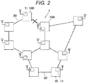
communication path 20 through which adevice 10A is communicably coupled to adevice 10B as illustrated inFIG. 2 , and then a malfunction occurs in thecommunication path 20 other than thecommunication path 20 in which the malfunction has already occurred. - Even in this case, if the latter malfunction occurs in the
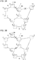
communication path 20 as illustrated in, for example, either one ofFIGS. 3A and 3B , theredundant system 1 according to the embodiment keeps all thedevices 10 communicably coupled via thecommunication paths 20. - Therefore, the
redundant system 1 continues to function as a single system. - In the case where the redundant system is formed in a single ring via the
communication paths 202 like theredundant system 200 illustrated inFIG. 8 , if a malfunction occurs in two of the communication paths of theredundant system 200, theredundant system 200 is divided into two groups (specifically, a group including thedevices 201A to 201D and a group including thedevices FIG. 9A , and theredundant system 200 no longer continues to function as a single system. - By contrast, in the case where the
redundant system 1 is configured such that themultiple devices 10 are communicably coupled in multiple ring shapes in a combined manner via thecommunication paths 20 as illustrated inFIG. 1 , even if a malfunction occurs in two of thecommunication paths 20, all thedevices 10 is kept communicably coupled via thecommunication paths 20, and theredundant system 1 continues to function as a single system as described above. - In the
redundant system 1 according to the embodiment, when a malfunction occurs in two of the communication paths, for example, when a malfunction occurs in thecommunication path 20 through which thedevice 10A is communicably coupled to thedevice 10B and then a malfunction occurs in thecommunication path 20 through which thedevice 10A is communicably coupled to adevice 10J as illustrated inFIG. 3A , thedevice 10A and thedevice 10J transmit signals (referred to below as "communication outage signals") indicating that the wired communication with thecorresponding devices communication paths 20 is disabled, via thecommunication paths 20 other than thecommunication paths 20 through which the wired communication is disabled, using the wired communication. - In this case, all the
devices 10 in theredundant system 1 are communicably coupled via thecommunication paths 20. Each of thedevices 10 receives both the communication outage signal transmitted from thedevice 10A and the communication outage signal transmitted from thedevice 10J. - Therefore, according to the embodiment, upon receipt of the communication outage signals from these two
devices 10, each of thedevices 10 recognizes that a malfunction has occurred in thecommunication paths 20 through which the twodevices 10 are communicably coupled and that all thedevices 10 are kept communicably coupled via the communication paths 20 (that is, theredundant system 1 continues to function as a single system) even when the malfunction has occurred. - In this case, each of the
devices 10 notifies a user of the occurrence of a malfunction, prompts the user for repair, and continues wired communication via thecommunication paths 20 with thedevices 10. - On the other hand, for example, it is assumed that a malfunction occurs in the
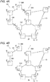
communication path 20 through which thedevice 10A is communicably coupled to thedevice 10B as illustrated inFIG. 2 and then a malfunction occurs in thecommunication path 20 through which adevice 10C is communicably coupled to adevice 10D as illustrated inFIG. 4A . - In this case, in the
redundant system 1, thedevices 10 of a group G1 (seeFIG. 4B ) including thedevices communication paths 20, and thedevices 10 of a group G2 including thedevices communication paths 20. However, disabled is wired communication between the groups G1 and G2 via thecommunication paths 20. - The
redundant system 1 is divided into two groups, that is, the groups G1 and G2. - When the two
communication paths 20 in which a malfunction has occurred are twocommunication paths 20 communicably coupled to, for example, thedevice 10B as illustrated inFIG. 5 , thedevice 10B becomes unable to perform wired communication with anydevices 10 other than thedevice 10B via thecommunication paths 20. - According to the embodiment, however, even when one device 10 (the
device 10B in this example) becomes unable to perform wired communication with anydevices 10 other than thedevice 10B via thecommunication paths 20, the onedevice 10 is treated as a group, that is, a group G4 consisting of thedevice 10B that is unable to perform wired communication with anydevices 10 other than thedevice 10B via thecommunication paths 20. - As described above, among the
devices 10 in theredundant system 1 in which a malfunction has occurred in two or more parts in theredundant system 1,multiple devices 10 capable of performing wired communication with each other via thecommunication paths 20 are treated as a group, and onedevice 10 that is unable to perform wired communication with thedevice 10 other than the onedevice 10 via thecommunication paths 20 is treated as a group. - Therefore, after a malfunction has occurred in two or more parts in the
redundant system 1, thedevices 10 of theredundant system 1 belong to any of groups. As a result, there may be a group includingmultiple devices 10 and a group consisting of onedevice 10. - In the following descriptions, wireless communication between a
device 10 of one group and adevice 10 of a group other than the one group may be referred to as wireless communication between the groups for simplification. - Description will be made on an example in which each group includes
multiple devices 10 as illustrated inFIGS. 4A and 4B , below. It is noted that the following description is applicable to an example in which a group consists of onedevice 10. - Depending on the
communication paths 20 in which a malfunction occurs, theredundant system 1 illustrated inFIG. 1 may continue to function as a single system as illustrated inFIGS. 3A and 3B , or theredundant system 1 may be divided into two groups G1 and G2 as illustrated inFIGS. 4A and 4B and disabled is wired communication between the groups G1 and G2 via thecommunication paths 20. - Therefore, according to the embodiment, each of the
devices 10 determines whether - (i) the
redundant system 1 is continuing to function as a single system or - (ii) the
redundant system 1 has been divided into the two groups G1 and G2, based on the communication outage signals transmitted from thedevices 10 that are unable to perform wired communication with theadjacent devices 10 via thecommunication paths 20 due to occurrence of a malfunction in thecommunication paths 20. - That is, when a malfunction occurs in, for example, the
communication path 20 through which thedevice 10A is communicably coupled to thedevice 10J as illustrated inFIG. 3A , both the communication outage signal transmitted from thedevice 10A and the communication outage signal transmitted from thedevice 10J are transmitted to all thedevices 10. - Therefore, upon receipt of the two communication outage signals, each of the
devices 10 determines that all thedevices 10 are kept communicably coupled via thecommunication paths 20 even though a malfunction has occurred (that is, theredundant system 1 continues to function as a single system). - In this case, each of the
devices 10 notifies a user of the occurrence of a malfunction, prompts the user for repair, and continues wired communication via thecommunication paths 20 with thedevices 10. - Alternatively, as illustrated in
FIGS. 4A and 4B , when a malfunction occurs in, for example, thecommunication path 20 through which thedevice 10C is communicably coupled to thedevice 10D, the communication outage signal from thedevice 10C is transmitted to thedevices 10 of the group G1, but the communication outage signal from thedevice 10D is not transmitted to thedevices 10 of the group G1. - In addition, the communication outage signal from the
device 10D is transmitted to thedevices 10 of the group G2, but the communication outage signal from thedevice 10C is not transmitted to thedevices 10 of the group G2. - As described above, according to the embodiment, when each of the
devices 10 receives the communication outage signal from onedevice 10 and does not receive the communication outage signal from theother device 10, each of thedevices 10 determines that a malfunction has occurred and theredundant system 1 has been divided into the two groups G1 and G2. - In the latter case, each of the
devices 10 recognizes which of thedevices 10 is communicable to each of thedevices 10 via thecommunication paths 20, by exchanging information withother devices 10. - For example, in the example illustrated in
FIGS. 4A and 4B , each of thedevices 10 of the group G1 including thedevice 10A recognizes (i) that the group G1 includes the seven devices 10 (including the each of the devices 10) communicable via thecommunication paths 20 and (ii) which of the tendevices 10 the group G1 includes. - In addition, each of the
devices 10 of the group G2 including thedevice 10B recognizes - (i) that the group G2 includes the three
devices 10 communicable via thecommunication paths 20 and - (ii) which of the ten
devices 10 the group G2 includes. - When each of the
devices 10 communicates with thedevices 10 of the group to which each of thedevices 10 belongs, each of thedevices 10 performs wired communication via thecommunication paths 20. When each of thedevices 10 communicates across groups, each of thedevices 10 switches to wireless communication using thewireless communication unit 11 to continue the communication. - Wireless communication between groups will be specifically described below.
- In the wireless communication between groups, single input and single output (SISO) wireless communication may be performed between one of the
devices 10 of the group G1 and one of thedevices 10 of the group G2. - However, wireless communication has a higher error rate and lower reliability than wired communication via the
communication paths 20. Instead of the SISO wireless communication, either one of multi input and multi output (MIMO) wireless communication, multi input and single output (MISO) wireless communication, and single input and multi output (SIMO) wireless communication may be performed between the groups G1 and G2. Such a configuration further improves the reliability of wireless communication between groups. - When either one of MIMO, MISO, and SIMO wireless communications is performed, for example, if a signal is transmitted from the
device 10B to thedevice 10A using wireless communication in the state illustrated inFIGS. 4A and 4B , the signal is transmitted from all (or one or ones) thedevices 10 of the group G2 and then received by all (or one or ones of) thedevices 10 of the group G1. - Upon receipt of the signal, all (or one or ones of) the
devices 10 of the group G1 transmit the received signal to thedevice 10A via thecommunication paths 20 using the wired communication. - Meanwhile, when wireless communication is performed between groups, the
devices 10 of different groups that perform wireless communication, the output of wireless communication, and the like may be improved based on the physical distance between thedevices 10 of the different groups, the noise strength of wireless communication, and the radio characteristics. - Specifically, when wireless communication is performed between, for example, the
device 10A and thedevice 10B in the state illustrated inFIGS. 4A and 4B , the communication strength of wireless communication may become weak if the physical distance between thedevice 10A and thedevice 10B is large. - In addition, if there is equipment that generates a large noise near either one of the
device 10A and thedevice 10B, a large noise may be added to the wireless communication between thedevices - In addition, when an obstacle is present between the
device 10A and thedevice 10B, the obstacle may interfere with the radio waves of wireless communication. Conversely, the radio waves of wireless communication between thedevice 10A and thedevice 10B may be amplified by reflection or diffraction by an object, such as a wall, other than thedevice 10A and thedevice 10B. - Therefore, when wireless communication is performed between the groups G1 and G2 as described above, wireless communication may be improved by determining the
devices 10 that perform transmission and reception in wireless communication so as to be improved those conditions and determining the output and the like in wireless communication. - In this case, at the time when a malfunction occurs and the
redundant system 1 is divided into two groups G1 and G2, an improvement process may be performed in one or ones of thedevices 10 of the groups G1 and G2 based on situations such as noise and an obstacle and the sensitivity of wireless communication in thedevices 10, to determine which of (one or ones of)devices 10 of the groups perform wireless communication and how much output power is used in wireless communication. - In addition, a table may be prepared in advance that defines which (one or ones of)
devices 10 of the groups performs wireless communication and how much output power is used in the wireless communication when a malfunction occurs in twocommunication paths 20 of theredundant system 1, for all combinations of twocommunication paths 20. - At the time when a malfunction occurs and the
redundant system 1 is divided into two groups G1 and G2, - (i) whether each of the
devices 10 performs wireless communication and - (ii) the strength of the wireless communication may be determined based on the table.
- As described above, the reliability of wireless communication is lower than that of wired communication via the
communication paths 20. - The
redundant system 1 according to the embodiment switches the communication between groups to wireless communication when a malfunction has occurred and theredundant system 1 has been divided into two groups. Since the reliability of wireless communication is lower than that of wired communication via thecommunication paths 20, such a measure is an emergency measure and is taken until wired communication via thecommunication paths 20 is recovered. - Since the reliability of wireless communication is lower than that of wired communication via the
communication paths 20, the amount of wireless communication is desirably reduced. - Accordingly, for example, two groups generated due to occurrence of a malfunction is classified into a main group and an isolated group. When communication between the groups is switched from wired communication via the
communication paths 20 to wireless communication, data including signals, information, and parameters (the same applies to the following) is transmitted from the isolated group to the main group using wireless communication, but no data is basically transmitted from the main group to the isolated group. - When the isolated group requests transmission of data, the main group may simply transmit the requested data to the isolated group using wireless communication.
- In this case, each group may be classified into a main group or an isolated group based on, for example, the number of
devices 10 of each group. For example, in the example illustrated inFIGS. 4A and 4B , the group G1 includes sevendevices 10 and the group G2 includes threedevices 10. Then, the group G1 is classified into the main group, and the group G2 is classified into the isolated group. - In addition, in the example illustrated in
FIG. 5 , a group G3 including thedevice 10A is classified into the main group, and a group G4 including thedevice 10B is classified into an isolated group. In an example illustrated inFIGS. 6A and 6B which will be described later, a group G5 including thedevice 10A is classified into the main group, and a group G6 including thedevice 10B is classified into the isolated group. - In this case, when a malfunction occurs, wireless communication is performed between the groups to exchange the number of the
devices 10 of the groups, so that each of thedevices 10 knows whether the group to which the each of thedevices 10 belongs is the main group or the isolated group. - For example, in the case where the
redundant system 1 includes a management device that manages theredundant system 1, the group including this management device may be classified into the main group, and the other group may be classified into the isolated group. As described above, the method for classification into the main group or the isolated group is determined as appropriate. - In this manner, wireless communication from the main group to the isolated group is simply limited to necessary communication, so that the amount of wireless communication in the entire
redundant system 1 is reduced while the reliability of the entireredundant system 1 is maintained. - The description has been made on the case in which a malfunction occurs in two
communication paths 20 in theredundant system 1. The above description is applicable to the case in which a malfunction occurs in three ormore communication paths 20. - In this case, even when a malfunction occurs in three or
more communication paths 20 of theredundant system 1, all thedevices 10 of theredundant system 1 may be kept communicably coupled via thecommunication paths 20 and theredundant system 1 continues to function as a single system, or theredundant system 1 may be divided into two groups as described above. Since the same configuration as above may be adopted in these cases, descriptions thereon will be omitted. - When a malfunction occurs in three or
more communication paths 20 of theredundant system 1 and theredundant system 1 is divided into three or more groups, communication between thedevices 10 of each group is performed using wired communication via thecommunication paths 20, and communication between the groups is performed using wireless communication. - Also in this case, one of the groups may be classified into the main group based on the number of the
devices 10 of the groups and the presence or absence of the management device. The groups other than the main group may be classified into isolated groups. - Similarly to the case in which a malfunction occurs in two
communication paths 20 of theredundant system 1, each of thedevices 10 may determine the group to be classified into the main group and the groups to be classified into the isolated groups at the time when a malfunction occurs in two ormore communication paths 20 of theredundant system 1. - In addition, a table may be prepared in advance that defines a group to be classified into the main group and groups to be classified into the isolated groups when a malfunction occurs in the
redundant system 1, for all combinations of two ormore communication paths 20. When a malfunction occurs, each of thedevices 10 may recognize the classification of the groups with reference to the table. - Next, description will be made on a case in which a malfunction occurs in the
device 10 using an example in which a malfunction occurs in thedevice 10C as illustrated inFIGS. 6A and 6B . - As illustrated in
FIGS. 6A and 6B , when a malfunction occurs in thecommunication path 20 through which, for example, thedevice 10A is communicably coupled to thedevice 10B and then a malfunction occurs in thedevice 10C, theredundant system 1 is also divided into two groups G5 and G6. - Accordingly, a process such as switching the communication between groups to wireless communication is performed in a similar manner as described above. It is noted here that this process is the same as above and descriptions thereon will be omitted.
- As described above, in the
redundant system 1 according to the embodiment, when a malfunction occurs in two or more parts in thedevices 10 and thecommunication paths 20 of theredundant system 1 in which thedevices 10 are communicably coupled in a ring shape via thecommunication paths 20, theredundant system 1 switches to wireless communication from the wired communication via thecommunication path 20 between - (i) the
device 10 of the group including thedevices 10 capable of performing the wired communication with each other via the communication paths 20 (or a group consisting of onedevice 10 incapable of performing wired communication via thecommunication paths 20 with anydevices 10 other than the one device 10) and - (ii) the
device 10 of another group incapable of performing wired communication via thecommunication paths 20 with the group, thereby continuing the communication. - Therefore, in the
redundant system 1 according to the embodiment, even when a malfunction occurs in two or more parts in theredundant system 1, communication between thedevices 10 in which no malfunction occurs continues. - There is room for improvement in that when a malfunction occurs in the
device 10C and the malfunction is left unrepaired, control of equipment and appliances to be uniquely processed by thedevice 10C may not be performed. - Accordingly, when a malfunction occurs in, for example, the
device 10C, the process to be uniquely performed by thedevice 10C is inherited to adevice 10 other than thedevice 10C. - This process will be described specifically below.
- As described above, when determining that a malfunction has occurred in the
redundant system 1, each of thedevices 10 communicates with theother devices 10, for example, exchanges information, recognizes thedevices 10 with which the each of thedevices 10 is communicable via thecommunication paths 20, performs wireless communication between groups, and recognizes which group is the main group. It is noted here that a group may consist of onedevice 10 as described above. - As a result of communication among the
devices 10, when adevice 10 belonging to no group is found (that is, thedevice 10 that returns no response), it is determined that a malfunction has occurred in the device 10 (thedevice 10C in this example). According to the embodiment, each of thedevices 10 determines that a malfunction has occurred in a certain device (thedevice 10C in this example). - In the embodiment, when a malfunction occurs in the device 10 (
device 10C in this example) as described above, adevice 10 of the main group inherits and performs the process originally performed by thedevice 10C in which a malfunction has occurred. - Such a configuration allows the devices 10 (or one of the devices 10) of the main group to inherit and perform the process originally performed by the
device 10C in which a malfunction has occurred, thereby preventing the process originally performed by thedevice 10C from being not performed. - In this case, the
device 10 of the isolated group does not inherit the process originally performed by thedevice 10C in which a malfunction has occurred, and performs its own process. - Then, the
devices 10 of the isolated group notify the main group of completion or non-completion of a certain process using wireless communication as well as the number of thedevices 10 of the isolated group. - In the case described above, when classification into the main group or the isolated group is determined such that, for example, the group including the management device of the
redundant system 1 is classified into the main group as described above, the management device may store, in advance, programs of all thedevices 10 of theredundant system 1. - With this configuration, even when a malfunction occurs in any of the
devices 10, since the management device stores the programs to be used, the management device may inherit and perform the process based on the programs or may cause one of thedevices 10 of the main group to inherit the process by transmitting the programs to be used to thedevice 10. - In addition, in the case where classification into the main group or the isolated group is determined based on, for example, the numbers of the
devices 10 of the groups as described above, it is difficult to know thedevice 10 or thecommunication path 20 in which a malfunction will occur in advance and it is difficult to know which of thedevices 10 will belong to a main group and inherit the process originally performed by thedevice 10 in which the malfunction occurs in advance. Therefore, each of thedevices 10 may store the programs of all thedevices 10 of theredundant system 1 in advance. - With this configuration, even when a malfunction occurs in any of the
devices 10, since any of thedevices 10 of the main group (group G5 in the example ofFIGS. 6A and 6B ) stores in advance the programs necessary for the process originally performed by thedevice 10 in which a malfunction has occurred, thedevice 10 may inherit and perform the process based on the programs. - In addition, when one of the
devices 10 of the main group inherits the process originally performed by thedevice 10C in which a malfunction has occurred as described above, for example, one of thedevices 10 of the main group that has enough processing power may inherit the process originally performed by thedevice 10C in which a malfunction has occurred. Alternatively,multiple devices 10 of the main group may inherit and perform the process in corporation. - In addition, the
device 10 communicably coupled to the equipment originally processed by thedevice 10 in which a malfunction has occurred may inherit the process. - When the
device 10 communicably coupled to the equipment originally processed by thedevice 10 in which a malfunction has occurred is present in the isolated group but is absent in the main group, thedevice 10 of the isolated group may inherit the process originally processed bydevice 10 in which a malfunction has occurred. - In addition, a table that contains all assumed cases in which a malfunction occurs in the
devices 10 and thecommunication paths 20 of theredundant system 1 may be prepared and, when a malfunction occurs, thedevice 10 that inherits the processing originally performed by thedevice 10 in which a malfunction has occurred may be determined based on the table. - It is appreciated that the present invention is not limited to the above embodiments, and modification may be made as appropriate without departing from the spirit of the invention.
-
- 1
- Redundant system
- 10
- Device
- 10A
- Device
- 10B
- Device
- 10C
- Device
- 10D
- Device
- 11
- Wireless communication unit
- 20
- Communication path
- G1
- Group
- G2
- Group
- G3
- Group
- G4
- Group
- G5
- Group
- 100
- System
- 101A
- Device
- 101B
- Device
- 101C
- Device
- 101D
- Device
- 101E
- Device
- 102
- Bus
- 200
- Redundant system
- 201A
- Device
- 201B
- v
- 201C
- Device
- 201D
- Device
- 201E
- Device
- 201F
- Device
- 202
- Communication path
Claims (5)
- A redundant system (1) comprising:- multiple devices (10) communicably coupled via communication paths, wherein- each of the devices (10) is communicably coupled via two or more of the communication paths (20) to two or more of the devices (10) other than the each of the devices (10),- each of the devices (10) is configured to perform wired communication via the two or more of the communication paths (20) with the devices (10) communicably coupled to each of the devices (10) via the two or more of the communication paths (20) in a normal state,- each of the devices (10) comprises a wireless communication unit (11), and
when each of the devices (10) communicates with two or more of the devices (10) other than each of the devices (10) under a condition that a malfunction occurs in two or more parts in the redundant system (1), then each of the devices (10)is configured to perform a wired communication via the communication path (20) with a counterpart device with which the wired communication via the communication path (20) is enabled, andis configured to switch from the wired communication via the communication path (20) to wireless communication and to continue communication with a counterpart device with which the wired communication via the communication path (20) is disabled. - The redundant system (1) according to claim 1,
wherein a malfunction comprises either one or both of a malfunction in the communication paths (20) and a malfunction in the devices (10). - The redundant system (1) according to claim 1 or 2,
wherein the wireless communication is of a multi input and multi output scheme, a multi input and single output scheme, or a single input and multi output scheme. - The redundant system (1) according to any one of claims 1 to 3,
wherein after the malfunction has occurred in two or more parts in the redundant system (1), the multiple devices (10) are classified into one or more groups (G1 to G5) each comprising multiple devices (10) capable of performing a wired communication via the communication paths (20) with each other,
if there is a device incapable of performing a wired communication via any communication path (20) with any of the other devices (10), the device is classified into a group, and
if the groups are classified into a main group and an isolated group, data is transmitted from a device of the isolated group to a device of the main group using a wireless communication and necessary data is simply transmitted from the device of the main group to the device of the isolated group using the wireless communication. - The redundant system (1) according to claim 4,
wherein if a malfunction occurs in one of the devices (10), the device of the main group inherits a process originally performed by the one of the devices (10) in which the malfunction has occurred and performs the process.
Applications Claiming Priority (2)
| Application Number | Priority Date | Filing Date | Title |
|---|---|---|---|
| JP2018220889 | 2018-11-27 | ||
| JP2019179204A JP7454349B2 (en) | 2018-11-27 | 2019-09-30 | redundant system |
Publications (2)
| Publication Number | Publication Date |
|---|---|
| EP3660680A1 true EP3660680A1 (en) | 2020-06-03 |
| EP3660680B1 EP3660680B1 (en) | 2023-01-04 |
Family
ID=68468581
Family Applications (1)
| Application Number | Title | Priority Date | Filing Date |
|---|---|---|---|
| EP19207046.4A Active EP3660680B1 (en) | 2018-11-27 | 2019-11-05 | Redundant system |
Country Status (2)
| Country | Link |
|---|---|
| US (1) | US11196615B2 (en) |
| EP (1) | EP3660680B1 (en) |
Families Citing this family (1)
| Publication number | Priority date | Publication date | Assignee | Title |
|---|---|---|---|---|
| WO2023043440A1 (en) * | 2021-09-15 | 2023-03-23 | Hewlett-Packard Development Company, L.P. | Network issue identifications |
Citations (4)
| Publication number | Priority date | Publication date | Assignee | Title |
|---|---|---|---|---|
| JPH08265319A (en) | 1995-03-20 | 1996-10-11 | Nec Telecom Syst Ltd | Duplex monitoring control system |
| US20060253726A1 (en) * | 2005-05-06 | 2006-11-09 | Vikas Kukshya | Fault-tolerant architecture for a distributed control system |
| JP2010033454A (en) * | 2008-07-30 | 2010-02-12 | Kyocera Corp | Information processor and information processing method |
| US20170242764A1 (en) * | 2016-02-23 | 2017-08-24 | Vmware, Inc. | High availability handling network segmentation in a cluster |
Family Cites Families (3)
| Publication number | Priority date | Publication date | Assignee | Title |
|---|---|---|---|---|
| JP4776374B2 (en) * | 2005-12-27 | 2011-09-21 | 株式会社東芝 | Redundant supervisory control system and redundant switching method for the same system |
| US9215124B2 (en) * | 2010-11-03 | 2015-12-15 | Broadcom Corporation | Unified vehicle network frame protocol |
| US10419271B2 (en) * | 2014-12-30 | 2019-09-17 | Lg Cns Co., Ltd. | Public transportation fee payment system and operating method thereof |
-
2019
- 2019-11-01 US US16/671,812 patent/US11196615B2/en active Active
- 2019-11-05 EP EP19207046.4A patent/EP3660680B1/en active Active
Patent Citations (4)
| Publication number | Priority date | Publication date | Assignee | Title |
|---|---|---|---|---|
| JPH08265319A (en) | 1995-03-20 | 1996-10-11 | Nec Telecom Syst Ltd | Duplex monitoring control system |
| US20060253726A1 (en) * | 2005-05-06 | 2006-11-09 | Vikas Kukshya | Fault-tolerant architecture for a distributed control system |
| JP2010033454A (en) * | 2008-07-30 | 2010-02-12 | Kyocera Corp | Information processor and information processing method |
| US20170242764A1 (en) * | 2016-02-23 | 2017-08-24 | Vmware, Inc. | High availability handling network segmentation in a cluster |
Also Published As
| Publication number | Publication date |
|---|---|
| EP3660680B1 (en) | 2023-01-04 |
| US20200169454A1 (en) | 2020-05-28 |
| US11196615B2 (en) | 2021-12-07 |
Similar Documents
| Publication | Publication Date | Title |
|---|---|---|
| TW200528988A (en) | Managing transmissions between devices | |
| JPH04117743A (en) | Optical transceiver | |
| EP3384612B1 (en) | Switch matrix with active and spare second ports and connection of a first port from an active second port to a spare second port on reduced performance on the second active port. | |
| EP4261699B1 (en) | Method and circuit for multiplexing usb interface, and electronic device and storage medium | |
| EP3588993A1 (en) | Broadcast sending method, device, terminal and storage medium | |
| CN112995070B (en) | Double-card switching system and method | |
| EP3660680B1 (en) | Redundant system | |
| US10595255B2 (en) | Wireless communication apparatus, system, and method | |
| CN111431668B (en) | Baud rate switching method based on multi-node UART communication, air conditioning system and processor | |
| US8626001B2 (en) | Optical communication card and optical transmission device | |
| JP2020091839A (en) | Redundant system | |
| CN100382535C (en) | Data communication device, data communication system, and data communication method | |
| EP4489353A1 (en) | Can communication apparatus and method | |
| KR102177230B1 (en) | Apparatus and method for serial communication control discriminating | |
| CN113300885B (en) | Network switching equipment and method | |
| WO2020230316A1 (en) | Communication terminal constituting multi-hop network, and multi-hop network | |
| EP1793626B1 (en) | System and method for implementing service switching | |
| CN117349208A (en) | Isolated serial interface bidirectional communication method, system, medium and master controller based on daisy chain frame structure | |
| WO2006136997A1 (en) | Communication network system | |
| US7440398B2 (en) | Fault tolerant communication apparatus | |
| JP3149047B2 (en) | Redundant data processor | |
| JP2003140704A (en) | Process controller | |
| CN117319183A (en) | Ring network communication fault identification method and device and distributed control ring network | |
| KR200206030Y1 (en) | Dual interface structure between the shelfs in the exchanger | |
| CN115835391A (en) | Data transmission method and equipment |
Legal Events
| Date | Code | Title | Description |
|---|---|---|---|
| PUAI | Public reference made under article 153(3) epc to a published international application that has entered the european phase |
Free format text: ORIGINAL CODE: 0009012 |
|
| STAA | Information on the status of an ep patent application or granted ep patent |
Free format text: STATUS: THE APPLICATION HAS BEEN PUBLISHED |
|
| AK | Designated contracting states |
Kind code of ref document: A1 Designated state(s): AL AT BE BG CH CY CZ DE DK EE ES FI FR GB GR HR HU IE IS IT LI LT LU LV MC MK MT NL NO PL PT RO RS SE SI SK SM TR |
|
| AX | Request for extension of the european patent |
Extension state: BA ME |
|
| STAA | Information on the status of an ep patent application or granted ep patent |
Free format text: STATUS: REQUEST FOR EXAMINATION WAS MADE |
|
| 17P | Request for examination filed |
Effective date: 20201203 |
|
| RBV | Designated contracting states (corrected) |
Designated state(s): AL AT BE BG CH CY CZ DE DK EE ES FI FR GB GR HR HU IE IS IT LI LT LU LV MC MK MT NL NO PL PT RO RS SE SI SK SM TR |
|
| STAA | Information on the status of an ep patent application or granted ep patent |
Free format text: STATUS: EXAMINATION IS IN PROGRESS |
|
| 17Q | First examination report despatched |
Effective date: 20210826 |
|
| GRAP | Despatch of communication of intention to grant a patent |
Free format text: ORIGINAL CODE: EPIDOSNIGR1 |
|
| STAA | Information on the status of an ep patent application or granted ep patent |
Free format text: STATUS: GRANT OF PATENT IS INTENDED |
|
| INTG | Intention to grant announced |
Effective date: 20220714 |
|
| GRAS | Grant fee paid |
Free format text: ORIGINAL CODE: EPIDOSNIGR3 |
|
| GRAA | (expected) grant |
Free format text: ORIGINAL CODE: 0009210 |
|
| STAA | Information on the status of an ep patent application or granted ep patent |
Free format text: STATUS: THE PATENT HAS BEEN GRANTED |
|
| AK | Designated contracting states |
Kind code of ref document: B1 Designated state(s): AL AT BE BG CH CY CZ DE DK EE ES FI FR GB GR HR HU IE IS IT LI LT LU LV MC MK MT NL NO PL PT RO RS SE SI SK SM TR |
|
| REG | Reference to a national code |
Ref country code: GB Ref legal event code: FG4D |
|
| REG | Reference to a national code |
Ref country code: CH Ref legal event code: EP |
|
| REG | Reference to a national code |
Ref country code: AT Ref legal event code: REF Ref document number: 1542460 Country of ref document: AT Kind code of ref document: T Effective date: 20230115 |
|
| REG | Reference to a national code |
Ref country code: DE Ref legal event code: R096 Ref document number: 602019023896 Country of ref document: DE |
|
| REG | Reference to a national code |
Ref country code: IE Ref legal event code: FG4D |
|
| REG | Reference to a national code |
Ref country code: LT Ref legal event code: MG9D |
|
| REG | Reference to a national code |
Ref country code: NL Ref legal event code: MP Effective date: 20230104 |
|
| REG | Reference to a national code |
Ref country code: AT Ref legal event code: MK05 Ref document number: 1542460 Country of ref document: AT Kind code of ref document: T Effective date: 20230104 |
|
| PG25 | Lapsed in a contracting state [announced via postgrant information from national office to epo] |
Ref country code: NL Free format text: LAPSE BECAUSE OF FAILURE TO SUBMIT A TRANSLATION OF THE DESCRIPTION OR TO PAY THE FEE WITHIN THE PRESCRIBED TIME-LIMIT Effective date: 20230104 |
|
| PG25 | Lapsed in a contracting state [announced via postgrant information from national office to epo] |
Ref country code: RS Free format text: LAPSE BECAUSE OF FAILURE TO SUBMIT A TRANSLATION OF THE DESCRIPTION OR TO PAY THE FEE WITHIN THE PRESCRIBED TIME-LIMIT Effective date: 20230104 Ref country code: PT Free format text: LAPSE BECAUSE OF FAILURE TO SUBMIT A TRANSLATION OF THE DESCRIPTION OR TO PAY THE FEE WITHIN THE PRESCRIBED TIME-LIMIT Effective date: 20230504 Ref country code: NO Free format text: LAPSE BECAUSE OF FAILURE TO SUBMIT A TRANSLATION OF THE DESCRIPTION OR TO PAY THE FEE WITHIN THE PRESCRIBED TIME-LIMIT Effective date: 20230404 Ref country code: LV Free format text: LAPSE BECAUSE OF FAILURE TO SUBMIT A TRANSLATION OF THE DESCRIPTION OR TO PAY THE FEE WITHIN THE PRESCRIBED TIME-LIMIT Effective date: 20230104 Ref country code: LT Free format text: LAPSE BECAUSE OF FAILURE TO SUBMIT A TRANSLATION OF THE DESCRIPTION OR TO PAY THE FEE WITHIN THE PRESCRIBED TIME-LIMIT Effective date: 20230104 Ref country code: HR Free format text: LAPSE BECAUSE OF FAILURE TO SUBMIT A TRANSLATION OF THE DESCRIPTION OR TO PAY THE FEE WITHIN THE PRESCRIBED TIME-LIMIT Effective date: 20230104 Ref country code: ES Free format text: LAPSE BECAUSE OF FAILURE TO SUBMIT A TRANSLATION OF THE DESCRIPTION OR TO PAY THE FEE WITHIN THE PRESCRIBED TIME-LIMIT Effective date: 20230104 Ref country code: AT Free format text: LAPSE BECAUSE OF FAILURE TO SUBMIT A TRANSLATION OF THE DESCRIPTION OR TO PAY THE FEE WITHIN THE PRESCRIBED TIME-LIMIT Effective date: 20230104 |
|
| PG25 | Lapsed in a contracting state [announced via postgrant information from national office to epo] |
Ref country code: SE Free format text: LAPSE BECAUSE OF FAILURE TO SUBMIT A TRANSLATION OF THE DESCRIPTION OR TO PAY THE FEE WITHIN THE PRESCRIBED TIME-LIMIT Effective date: 20230104 Ref country code: PL Free format text: LAPSE BECAUSE OF FAILURE TO SUBMIT A TRANSLATION OF THE DESCRIPTION OR TO PAY THE FEE WITHIN THE PRESCRIBED TIME-LIMIT Effective date: 20230104 Ref country code: IS Free format text: LAPSE BECAUSE OF FAILURE TO SUBMIT A TRANSLATION OF THE DESCRIPTION OR TO PAY THE FEE WITHIN THE PRESCRIBED TIME-LIMIT Effective date: 20230504 Ref country code: GR Free format text: LAPSE BECAUSE OF FAILURE TO SUBMIT A TRANSLATION OF THE DESCRIPTION OR TO PAY THE FEE WITHIN THE PRESCRIBED TIME-LIMIT Effective date: 20230405 Ref country code: FI Free format text: LAPSE BECAUSE OF FAILURE TO SUBMIT A TRANSLATION OF THE DESCRIPTION OR TO PAY THE FEE WITHIN THE PRESCRIBED TIME-LIMIT Effective date: 20230104 |
|
| REG | Reference to a national code |
Ref country code: DE Ref legal event code: R097 Ref document number: 602019023896 Country of ref document: DE |
|
| PG25 | Lapsed in a contracting state [announced via postgrant information from national office to epo] |
Ref country code: SM Free format text: LAPSE BECAUSE OF FAILURE TO SUBMIT A TRANSLATION OF THE DESCRIPTION OR TO PAY THE FEE WITHIN THE PRESCRIBED TIME-LIMIT Effective date: 20230104 Ref country code: RO Free format text: LAPSE BECAUSE OF FAILURE TO SUBMIT A TRANSLATION OF THE DESCRIPTION OR TO PAY THE FEE WITHIN THE PRESCRIBED TIME-LIMIT Effective date: 20230104 Ref country code: EE Free format text: LAPSE BECAUSE OF FAILURE TO SUBMIT A TRANSLATION OF THE DESCRIPTION OR TO PAY THE FEE WITHIN THE PRESCRIBED TIME-LIMIT Effective date: 20230104 Ref country code: DK Free format text: LAPSE BECAUSE OF FAILURE TO SUBMIT A TRANSLATION OF THE DESCRIPTION OR TO PAY THE FEE WITHIN THE PRESCRIBED TIME-LIMIT Effective date: 20230104 Ref country code: CZ Free format text: LAPSE BECAUSE OF FAILURE TO SUBMIT A TRANSLATION OF THE DESCRIPTION OR TO PAY THE FEE WITHIN THE PRESCRIBED TIME-LIMIT Effective date: 20230104 |
|
| PLBE | No opposition filed within time limit |
Free format text: ORIGINAL CODE: 0009261 |
|
| STAA | Information on the status of an ep patent application or granted ep patent |
Free format text: STATUS: NO OPPOSITION FILED WITHIN TIME LIMIT |
|
| PG25 | Lapsed in a contracting state [announced via postgrant information from national office to epo] |
Ref country code: SK Free format text: LAPSE BECAUSE OF FAILURE TO SUBMIT A TRANSLATION OF THE DESCRIPTION OR TO PAY THE FEE WITHIN THE PRESCRIBED TIME-LIMIT Effective date: 20230104 |
|
| 26N | No opposition filed |
Effective date: 20231005 |
|
| PG25 | Lapsed in a contracting state [announced via postgrant information from national office to epo] |
Ref country code: SI Free format text: LAPSE BECAUSE OF FAILURE TO SUBMIT A TRANSLATION OF THE DESCRIPTION OR TO PAY THE FEE WITHIN THE PRESCRIBED TIME-LIMIT Effective date: 20230104 |
|
| PG25 | Lapsed in a contracting state [announced via postgrant information from national office to epo] |
Ref country code: IT Free format text: LAPSE BECAUSE OF FAILURE TO SUBMIT A TRANSLATION OF THE DESCRIPTION OR TO PAY THE FEE WITHIN THE PRESCRIBED TIME-LIMIT Effective date: 20230104 |
|
| REG | Reference to a national code |
Ref country code: CH Ref legal event code: PL |
|
| PG25 | Lapsed in a contracting state [announced via postgrant information from national office to epo] |
Ref country code: MC Free format text: LAPSE BECAUSE OF FAILURE TO SUBMIT A TRANSLATION OF THE DESCRIPTION OR TO PAY THE FEE WITHIN THE PRESCRIBED TIME-LIMIT Effective date: 20230104 |
|
| PG25 | Lapsed in a contracting state [announced via postgrant information from national office to epo] |
Ref country code: LU Free format text: LAPSE BECAUSE OF NON-PAYMENT OF DUE FEES Effective date: 20231105 |
|
| PG25 | Lapsed in a contracting state [announced via postgrant information from national office to epo] |
Ref country code: CH Free format text: LAPSE BECAUSE OF NON-PAYMENT OF DUE FEES Effective date: 20231130 |
|
| GBPC | Gb: european patent ceased through non-payment of renewal fee |
Effective date: 20231105 |
|
| PG25 | Lapsed in a contracting state [announced via postgrant information from national office to epo] |
Ref country code: MC Free format text: LAPSE BECAUSE OF FAILURE TO SUBMIT A TRANSLATION OF THE DESCRIPTION OR TO PAY THE FEE WITHIN THE PRESCRIBED TIME-LIMIT Effective date: 20230104 Ref country code: LU Free format text: LAPSE BECAUSE OF NON-PAYMENT OF DUE FEES Effective date: 20231105 Ref country code: CH Free format text: LAPSE BECAUSE OF NON-PAYMENT OF DUE FEES Effective date: 20231130 |
|
| REG | Reference to a national code |
Ref country code: BE Ref legal event code: MM Effective date: 20231130 |
|
| REG | Reference to a national code |
Ref country code: IE Ref legal event code: MM4A |
|
| PG25 | Lapsed in a contracting state [announced via postgrant information from national office to epo] |
Ref country code: IE Free format text: LAPSE BECAUSE OF NON-PAYMENT OF DUE FEES Effective date: 20231105 |
|
| PG25 | Lapsed in a contracting state [announced via postgrant information from national office to epo] |
Ref country code: GB Free format text: LAPSE BECAUSE OF NON-PAYMENT OF DUE FEES Effective date: 20231105 |
|
| PG25 | Lapsed in a contracting state [announced via postgrant information from national office to epo] |
Ref country code: BE Free format text: LAPSE BECAUSE OF NON-PAYMENT OF DUE FEES Effective date: 20231130 |
|
| PG25 | Lapsed in a contracting state [announced via postgrant information from national office to epo] |
Ref country code: IE Free format text: LAPSE BECAUSE OF NON-PAYMENT OF DUE FEES Effective date: 20231105 Ref country code: GB Free format text: LAPSE BECAUSE OF NON-PAYMENT OF DUE FEES Effective date: 20231105 Ref country code: BE Free format text: LAPSE BECAUSE OF NON-PAYMENT OF DUE FEES Effective date: 20231130 |
|
| PG25 | Lapsed in a contracting state [announced via postgrant information from national office to epo] |
Ref country code: BG Free format text: LAPSE BECAUSE OF FAILURE TO SUBMIT A TRANSLATION OF THE DESCRIPTION OR TO PAY THE FEE WITHIN THE PRESCRIBED TIME-LIMIT Effective date: 20230104 |
|
| PG25 | Lapsed in a contracting state [announced via postgrant information from national office to epo] |
Ref country code: BG Free format text: LAPSE BECAUSE OF FAILURE TO SUBMIT A TRANSLATION OF THE DESCRIPTION OR TO PAY THE FEE WITHIN THE PRESCRIBED TIME-LIMIT Effective date: 20230104 |
|
| PG25 | Lapsed in a contracting state [announced via postgrant information from national office to epo] |
Ref country code: CY Free format text: LAPSE BECAUSE OF FAILURE TO SUBMIT A TRANSLATION OF THE DESCRIPTION OR TO PAY THE FEE WITHIN THE PRESCRIBED TIME-LIMIT; INVALID AB INITIO Effective date: 20191105 |
|
| PG25 | Lapsed in a contracting state [announced via postgrant information from national office to epo] |
Ref country code: HU Free format text: LAPSE BECAUSE OF FAILURE TO SUBMIT A TRANSLATION OF THE DESCRIPTION OR TO PAY THE FEE WITHIN THE PRESCRIBED TIME-LIMIT; INVALID AB INITIO Effective date: 20191105 |
|
| PG25 | Lapsed in a contracting state [announced via postgrant information from national office to epo] |
Ref country code: TR Free format text: LAPSE BECAUSE OF FAILURE TO SUBMIT A TRANSLATION OF THE DESCRIPTION OR TO PAY THE FEE WITHIN THE PRESCRIBED TIME-LIMIT Effective date: 20230104 |
|
| PGFP | Annual fee paid to national office [announced via postgrant information from national office to epo] |
Ref country code: DE Payment date: 20251119 Year of fee payment: 7 |
|
| PGFP | Annual fee paid to national office [announced via postgrant information from national office to epo] |
Ref country code: FR Payment date: 20251126 Year of fee payment: 7 |