EP3660537A1 - Procédé et dispositif de détection environnementale - Google Patents
Procédé et dispositif de détection environnementale Download PDFInfo
- Publication number
- EP3660537A1 EP3660537A1 EP19209160.1A EP19209160A EP3660537A1 EP 3660537 A1 EP3660537 A1 EP 3660537A1 EP 19209160 A EP19209160 A EP 19209160A EP 3660537 A1 EP3660537 A1 EP 3660537A1
- Authority
- EP
- European Patent Office
- Prior art keywords
- signal
- radar
- signals
- comparison
- sigc21
- Prior art date
- Legal status (The legal status is an assumption and is not a legal conclusion. Google has not performed a legal analysis and makes no representation as to the accuracy of the status listed.)
- Pending
Links
Images


Classifications
-
- G—PHYSICS
- G01—MEASURING; TESTING
- G01S—RADIO DIRECTION-FINDING; RADIO NAVIGATION; DETERMINING DISTANCE OR VELOCITY BY USE OF RADIO WAVES; LOCATING OR PRESENCE-DETECTING BY USE OF THE REFLECTION OR RERADIATION OF RADIO WAVES; ANALOGOUS ARRANGEMENTS USING OTHER WAVES
- G01S13/00—Systems using the reflection or reradiation of radio waves, e.g. radar systems; Analogous systems using reflection or reradiation of waves whose nature or wavelength is irrelevant or unspecified
- G01S13/88—Radar or analogous systems specially adapted for specific applications
- G01S13/89—Radar or analogous systems specially adapted for specific applications for mapping or imaging
- G01S13/90—Radar or analogous systems specially adapted for specific applications for mapping or imaging using synthetic aperture techniques, e.g. synthetic aperture radar [SAR] techniques
- G01S13/9021—SAR image post-processing techniques
- G01S13/9023—SAR image post-processing techniques combined with interferometric techniques
-
- G—PHYSICS
- G01—MEASURING; TESTING
- G01S—RADIO DIRECTION-FINDING; RADIO NAVIGATION; DETERMINING DISTANCE OR VELOCITY BY USE OF RADIO WAVES; LOCATING OR PRESENCE-DETECTING BY USE OF THE REFLECTION OR RERADIATION OF RADIO WAVES; ANALOGOUS ARRANGEMENTS USING OTHER WAVES
- G01S7/00—Details of systems according to groups G01S13/00, G01S15/00, G01S17/00
- G01S7/02—Details of systems according to groups G01S13/00, G01S15/00, G01S17/00 of systems according to group G01S13/00
- G01S7/40—Means for monitoring or calibrating
- G01S7/4004—Means for monitoring or calibrating of parts of a radar system
- G01S7/4021—Means for monitoring or calibrating of parts of a radar system of receivers
-
- G—PHYSICS
- G01—MEASURING; TESTING
- G01S—RADIO DIRECTION-FINDING; RADIO NAVIGATION; DETERMINING DISTANCE OR VELOCITY BY USE OF RADIO WAVES; LOCATING OR PRESENCE-DETECTING BY USE OF THE REFLECTION OR RERADIATION OF RADIO WAVES; ANALOGOUS ARRANGEMENTS USING OTHER WAVES
- G01S13/00—Systems using the reflection or reradiation of radio waves, e.g. radar systems; Analogous systems using reflection or reradiation of waves whose nature or wavelength is irrelevant or unspecified
- G01S13/003—Bistatic radar systems; Multistatic radar systems
-
- G—PHYSICS
- G01—MEASURING; TESTING
- G01S—RADIO DIRECTION-FINDING; RADIO NAVIGATION; DETERMINING DISTANCE OR VELOCITY BY USE OF RADIO WAVES; LOCATING OR PRESENCE-DETECTING BY USE OF THE REFLECTION OR RERADIATION OF RADIO WAVES; ANALOGOUS ARRANGEMENTS USING OTHER WAVES
- G01S13/00—Systems using the reflection or reradiation of radio waves, e.g. radar systems; Analogous systems using reflection or reradiation of waves whose nature or wavelength is irrelevant or unspecified
- G01S13/88—Radar or analogous systems specially adapted for specific applications
- G01S13/89—Radar or analogous systems specially adapted for specific applications for mapping or imaging
- G01S13/90—Radar or analogous systems specially adapted for specific applications for mapping or imaging using synthetic aperture techniques, e.g. synthetic aperture radar [SAR] techniques
- G01S13/9021—SAR image post-processing techniques
-
- G—PHYSICS
- G01—MEASURING; TESTING
- G01S—RADIO DIRECTION-FINDING; RADIO NAVIGATION; DETERMINING DISTANCE OR VELOCITY BY USE OF RADIO WAVES; LOCATING OR PRESENCE-DETECTING BY USE OF THE REFLECTION OR RERADIATION OF RADIO WAVES; ANALOGOUS ARRANGEMENTS USING OTHER WAVES
- G01S7/00—Details of systems according to groups G01S13/00, G01S15/00, G01S17/00
- G01S7/02—Details of systems according to groups G01S13/00, G01S15/00, G01S17/00 of systems according to group G01S13/00
- G01S7/023—Interference mitigation, e.g. reducing or avoiding non-intentional interference with other HF-transmitters, base station transmitters for mobile communication or other radar systems, e.g. using electro-magnetic interference [EMI] reduction techniques
-
- G—PHYSICS
- G01—MEASURING; TESTING
- G01S—RADIO DIRECTION-FINDING; RADIO NAVIGATION; DETERMINING DISTANCE OR VELOCITY BY USE OF RADIO WAVES; LOCATING OR PRESENCE-DETECTING BY USE OF THE REFLECTION OR RERADIATION OF RADIO WAVES; ANALOGOUS ARRANGEMENTS USING OTHER WAVES
- G01S7/00—Details of systems according to groups G01S13/00, G01S15/00, G01S17/00
- G01S7/02—Details of systems according to groups G01S13/00, G01S15/00, G01S17/00 of systems according to group G01S13/00
- G01S7/35—Details of non-pulse systems
- G01S7/352—Receivers
-
- G—PHYSICS
- G01—MEASURING; TESTING
- G01S—RADIO DIRECTION-FINDING; RADIO NAVIGATION; DETERMINING DISTANCE OR VELOCITY BY USE OF RADIO WAVES; LOCATING OR PRESENCE-DETECTING BY USE OF THE REFLECTION OR RERADIATION OF RADIO WAVES; ANALOGOUS ARRANGEMENTS USING OTHER WAVES
- G01S13/00—Systems using the reflection or reradiation of radio waves, e.g. radar systems; Analogous systems using reflection or reradiation of waves whose nature or wavelength is irrelevant or unspecified
- G01S13/87—Combinations of radar systems, e.g. primary radar and secondary radar
-
- G—PHYSICS
- G01—MEASURING; TESTING
- G01S—RADIO DIRECTION-FINDING; RADIO NAVIGATION; DETERMINING DISTANCE OR VELOCITY BY USE OF RADIO WAVES; LOCATING OR PRESENCE-DETECTING BY USE OF THE REFLECTION OR RERADIATION OF RADIO WAVES; ANALOGOUS ARRANGEMENTS USING OTHER WAVES
- G01S13/00—Systems using the reflection or reradiation of radio waves, e.g. radar systems; Analogous systems using reflection or reradiation of waves whose nature or wavelength is irrelevant or unspecified
- G01S13/88—Radar or analogous systems specially adapted for specific applications
- G01S13/89—Radar or analogous systems specially adapted for specific applications for mapping or imaging
- G01S13/90—Radar or analogous systems specially adapted for specific applications for mapping or imaging using synthetic aperture techniques, e.g. synthetic aperture radar [SAR] techniques
Definitions
- the invention relates to a radar system for detecting an environment of a moving object and a corresponding method.
- radar is used to detect the surroundings of a moving object, such as a vehicle, in particular an autonomous vehicle, a robot (or part of it), a crane system (or part of it), etc.
- the aim is to record the environment as precisely as possible, particularly with regard to distance, lateral position, speed and, if necessary, self-movement.
- the exact recording consists of a good separation (differentiation) of individual goals as well as the most accurate recording of the individual separated goals.
- ⁇ v c 2nd T sw ⁇ f c with T SW as the measurement duration and f c as the center frequency of the radar signal.
- f start as the start frequency of the signal
- l ant as the extension of the antennas (or the aperture of the antenna in the plane in which the angle is measured).
- the depth and speed resolution and accuracy that can be achieved with conventional radar systems are sufficient for most tasks in the field of environment detection.
- An important limiting factor in the environment detection is the angle resolution achieved so far (i.e. the ability to separate or resolve multiple adjacent targets over the angle) and the accuracy of the angle measurement.
- a high angular resolution and accuracy can be achieved via a large, spatially extended antenna array, as for example in Hardware Realization of a 2 mx 1 m Fully Electronic Real-Time mm-Wave Imaging System, A. Schiessl, A. Genghammer, S. Ahmed, L.-P. Schmidt, EUSAR 2012, or BLASTDAR - A Large Radar Sensor Array System for Blast Furnace Burden Surface Imaging, D. Zankl et al., IEEE Sensor Jounal, Vol. 15, No. 10, Oct. 2015 .
- HF high frequency
- substrates that are technically complex to manufacture and handle.
- RF antennas of a certain size or more can be problematic with regard to the radiation and coherence length of the individual paths.
- Arrangements with several substrates and connecting cables between them are technically very complex or cannot be implemented in a phase-stable manner at the commonly used frequencies (often above 10 GHz) and therefore do not represent a practical alternative.
- it is considered problematic in the prior art that known methods for Increasing the (lateral) accuracy and resolution of radar systems are comparatively complex and time-consuming or cannot be implemented in practice.
- the object of the invention is to propose a method or a system for environment detection which enables a comparatively high (lateral) accuracy and resolution with little effort.
- This object is achieved in particular by a radar system for detecting an environment of a moving object according to claim 1 and a corresponding method according to claim 14.
- the object is achieved by a radar system for detecting an environment of a moving object, in particular a vehicle and / or a transport device, such as in particular a crane, the system being mountable or mountable on the moving object, the radar System comprises at least two (non-coherent) radar modules with at least one transmitting and at least one receiving antenna, the Radar modules are arranged or can be arranged in a distributed manner on the moving object, at least one evaluation device being provided, which is configured to process transmit and receive signals of the radar modules into modified measurement signals in such a way that the modified measurement signals are coherent with one another (as if the transmit and Received signals from which they were derived come from a common source).
- the radar System comprises at least two (non-coherent) radar modules with at least one transmitting and at least one receiving antenna, the Radar modules are arranged or can be arranged in a distributed manner on the moving object, at least one evaluation device being provided, which is configured to process transmit and receive signals of the radar modules into modified measurement signals in such a
- a core idea of the invention is to configure the radar system in such a way that the transmit and receive signals of the radar modules are processed into modified measurement signals (in postprocessing) such that the signals (which are fundamentally non-coherent) are used to produce coherent, modified measurement signals be generated.
- modified measurement signals in postprocessing
- the signals which are fundamentally non-coherent
- the at least two radar modules are preferably connected to one another via a bus system.
- the at least two radar modules can each form an independent structural unit.
- the at least two radar modules can be separated from one another (spatially) or spaced apart (for example by at least 10 cm).
- the radar system in particular the evaluation device, is particularly preferably configured to form a comparison comparison signal from the first comparison signal and the further comparison signal. Also with regard to the formation of the comparison comparison signal DE 10 2014 104 273 A1 referred, whereby by reference, the relevant disclosure content should be part of the present disclosure.
- the system in particular the evaluation device, is configured to compensate for deviations in the comparison signals caused by systematic deviations in the radar modules in a first step and for at least one in a second step to use a complex value from a first of the two comparison signals or from a signal that was derived from this first comparison signal to adapt at least one complex value of the second of the two comparison signals or a value of a signal that was derived from this second comparison signal and to form such an adapted signal, the adaptation taking place in such a way that the vectorial sum or the difference of the complex values is formed by a mathematical operation, or the sum or the difference of the phases of the complex values is formed.
- Method II or configuration II realizes a radar system which, in the present case of the environment detection, in particular in combination with methods for radar imaging, allows a particularly high resolution or accuracy in the detection with simple means and in particular without a particularly large computing effort.
- the comparison comparison signal in which the two comparison signals are processed with one another - in particular conjugate multiplication complex - can correspond to a comparison signal generated with a coherent radar system.
- the first and / or second radar module preferably has (in each case) at least one, more preferably at least two (in particular its own) transmitting antenna (s) and / or at least one, preferably at least two (in particular its own) receiving antenna (s).
- the first and / or the second radar module (in each case) have at most four, preferably at most three (in particular own) transmitting antennas and / or at most five (preferably at most four) receiving antennas.
- the radar modules therefore preferably have at least one transmitting and at least one receiving antenna.
- the transmitting antenna and the receiving antenna can also be designed as a (common) transmitting and receiving antenna (that is, as a single antenna both for transmitting and for receiving).
- a plurality of transmit and receive antennas are preferably accommodated on one module, further preferably 1 to 3 transmit antennas and 2 to 4 receive antennas (which has proven to be an advantageous compromise between size and array configuration for the present application).
- the radar modules preferably comprise (in each case) a device for generating the HF signal (HF generator).
- the radar modules can have a device (comprising one or more antennas) for transmitting the RF signal and a device (comprising one or more antennas) for receiving the RF signal.
- the radar modules (each) can have a device for converting the RF signal to a lower frequency level, for example by means of a mixer or correlator.
- the radar modules (each) have their own (local) clock source for the system clock and possibly an AD converter.
- the radar modules can be arranged in a distributed manner, for example around a vehicle and / or looking ahead to cover the direction of movement or looking down, for example, in a crane system.
- the radar modules can then exchange the signals received either with one another or with a central processing unit (evaluation unit). This is preferably done via a (digital) data bus.
- Antennas of the (individual) radar modules can represent individual antenna elements.
- the radar modules are preferably arranged comparatively far apart, for example at a distance of at least 5 cm, preferably at least 10 cm, even more preferably at least 40 cm.
- a maximum distance can be less than 10 m, preferably less than 5 m, even more preferably less than 2 m, even more preferably less than 1.50 m.
- the radar modules are arranged so far apart that the resulting aperture is under-populated (i.e. there is only a smaller proportion of transmit and receive antennas or transmit and receive patches via a complete antenna array; sparse array).
- understaffed arrays usually have high side lobes. This can be optimized by individual arrangements. At least three radar modules are particularly preferably used, as a result of which the side lobes can be suppressed further.
- a sparse array is also an arrangement in which the transmit and receive antennas are not fully occupied in a periodic grid.
- a calibration measurement is preferably carried out with the radar modules (preferably after the individual radar modules have been installed) a single target well known in position).
- the radar modules preferably after the individual radar modules have been installed
- a single target well known in position By comparing the actually measured angle with a predetermined angle, (optimal) correction factors can be calculated for each reception path. It is particularly preferred to adapt the (complex) correction terms for each reception path in such a way that a peak for the known target becomes as high and narrow as possible. This enables different phase offsets of the radar modules to be compensated for.
- the (complex) correction terms can be adaptively adapted so that the estimation of the angle to a target delivers a (possible) consistent result from all radar modules.
- the radar system in particular the evaluation device, is preferably configured to determine an angular position of a surrounding structure by means of a phase monopulse method.
- the system in particular the evaluation device, can be configured to estimate, in particular to determine, the angular position of a / the surrounding structure by means of a method in the state space.
- the radar system can be configured so that targets are first separated according to distance and speed criteria, for example using range Doppler evaluation. The angle can then be determined by processing using interferometry (also called phase monopulse method in radar technology). For example, in a first step, a range Doppler diagram can be generated for each reception channel. A phase difference between two (closely) adjacent channels can then be determined for specific targets in a radar spectrum.
- the phase difference to a channel further away can then be determined in order to increase the accuracy.
- the accuracy can be increased by the (now) significantly increased base length between the channels.
- the MUSIC method can preferably be used Multiple Emitter - Location and Signal - Parameter Estimation, R. Schmidt, IEEE TRANSACTIONS ON ANTENNAS AND PROPAGATION, VOL. AP-34, NO.3, MARCH 1986 (particularly preferred for side lobe suppression in sparse arrays) can be used.
- the Capon process can be carried out according to High-Resolution Frequency-Wavenumber Spectrum Analysis, J.
- Capon Proceedings of the IEEE, Vol. 57, No. August 8, 1969 , can be used.
- the Capon method is particularly preferred because it does not require an assumption about the number of targets.
- Such an estimation can be carried out in state space methods on the basis of an amount of eigenvalues of a covariance matrix and is comparatively difficult to carry out in practice, in particular with coherent signals, since these do not differ significantly in amount.
- a correction of the hypothesis to be checked (referred to in this context as "steering vector") should preferably be carried out in this application.
- the system in particular the evaluation device, is preferably configured to detect a surrounding structure by means of the holography method, further preferably by means of the holography method, an angular position and / or an, in particular vectorial (relative), speed and / or an, in particular vectorial (relative), Estimating acceleration of the surrounding structure.
- the system in particular the evaluation device, is configured to carry out a calibration by means of the holography method.
- the radar system in particular the evaluation device, is preferably configured to have a (lateral) speed or a speed vector, in particular by means of a method for comparing a change in To determine the difference phases of reception channels.
- the system in particular the evaluation device, is preferably configured to determine a (lateral) acceleration or an acceleration vector, in particular by means of a method for comparing a change in differential phases of reception channels.
- a significantly enlarged aperture can also be used to improve the (vectorial) motion estimation.
- Previous radar systems usually only estimate the radial speed of a system using the Doppler effect. However, there is the possibility of additionally estimating the change in a phase difference between the channels over several reception channels. A lateral speed can be estimated from this.
- these fundamental considerations only provide precise results when the antennas are spaced apart.
- a sparse array is therefore particularly preferably constructed in order to be able to carry out a precise estimate with at least two modules at a greater distance (for example greater than 10 cm).
- a preferred realization of an evaluation can be carried out in the FMCW chirp sequence method.
- a burst of several, for example 128, frequency ramps can be sent simultaneously by the at least two radar modules (or overlapping in time).
- the received signals can then, for example S. Roehr, P. Gulden, and M. Vossiek, "Precise Distance and Velocity Measurement for Real Time Locating in Multipath Environments Using a Frequency-Modulated Continuous-Wave Secondary Radar Approach," IEEE Trans. Microw. Theory Tech., Vol. 56, no.10, pp. 2329-2339, Oct. 2008 , be separated.
- a processing step can then take place according to, for example, method II or configuration II for an indirect path.
- a range-doppler diagram can then be calculated (for each path) and the object position and speed can be determined.
- the angular position can be determined from the phase difference of the receiving channels using known methods (for example using phase monopulse or holography).
- a change in the phase difference from ramp to ramp can then be determined (angular velocity).
- This can then be measured with a measured distance into the lateral speed can be converted.
- the vectorial speed can then be determined as the sum of the lateral and radial speeds. This procedure improves the environment detection considerably, since the complete motion vector of the objects is then available in the environment.
- the measurement accuracy of the lateral speed is improved when a distance between the radar modules (a base between the modules) is large.
- a (lateral) acceleration (by again differentiating or subtracting the phase difference changes) can also be determined, in particular when using at least three receiving antennas. If one then determines a radial acceleration from at least three radar spectra recorded in succession, the vectorial acceleration can also be determined. In this context too, it is particularly advantageous if the antennas are at a comparatively large distance from one another.
- the radar image is therefore advantageously calculated holographically, for example according to A Rotating Synthetic Aperture Radar Imaging Concept for Robot Navigation, F. Ali, G. Bauer and M. Vossiek, IEEE TRANSACTIONS ON MICROWA VE THEORY AND TECHNIQUES, VOL. 62, NO. 7, JULY 2014 .
- This disclosure is hereby, by reference, part of the present disclosure (in particular with regard to the holographic calculation).
- the system in particular the evaluation device, is preferably configured for a SAR application and / or a (SAR) imaging method.
- SAR stands for Synthetic Aperture Radar.
- the use of a large (distributed) aperture is advantageous for SAR applications.
- the radar modules are preferably arranged or can be arranged at different heights on the moving object, in particular for measuring a height of an environmental object in an environment of the moving object, preferably by means of (interferometric) SAR processing.
- the radar modules can, for example, be at a distance of at least 5 cm, preferably at least 10 cm, still more preferably at least 25 cm, in the vertical direction.
- a bumper of a motor vehicle and / or a second radar module can be arranged on / in the roof of the motor vehicle and / or at least one radar module in the region of the interior mirror.
- the height measurement or height detection for example for automatic parking processes, is significantly improved.
- An arrangement with three or more systems at different heights is also advantageous.
- a time difference between several, in particular all, stations can then be used, in particular also in accordance with the procedure in the German patent application with the application number, which was not yet published at the time of the application DE 10 2015 121 724.4 or the corresponding international patent application with the application number PCT / EP2016 / 07596 .
- a phase noise or phase variations are corrected (it being possible for the system, in particular the evaluation device, to be configured accordingly).
- the system, in particular the evaluation device is preferably configured to have a phase noise component in a term for a variation within a measurement spectrum (or a sweep or a ramp) and a variation from measurement spectrum to measurement spectrum (or from sweep to sweep or from ramp to ramp) ) to structure.
- the variation from measurement spectrum to measurement spectrum is preferably determined (and possibly corrected) as the first (separate) step. This can significantly improve the accuracy of a measurement result.
- a / the variation of the phase noise component from measurement spectrum to measurement spectrum is preferably determined as a (common) component in both stations from the (common) variation of the phase in each spectrum, preferably about the dot product of the two measurement spectra.
- Two (of the two) measurement spectra are preferably added. These measures also improve the accuracy of the measurement result.
- the amplitudes of the spectra can be normalized beforehand to an absolute normal or to one another.
- phase noise or phase variations can be corrected in a simple manner.
- the radar modules can be arranged stationary in this case.
- An (optionally independent) aspect of the invention is (accordingly) a radar system (with movable or stationary radar modules or non-coherent transceiver units), in particular for detecting an environment of an (moving or non-moving) object , the system being mounted or mountable in particular on the object, the radar system comprising at least two (in particular distributed) non-coherent radar modules with at least one transmitting and at least one receiving antenna, wherein the radar modules are arranged or can be arranged in particular distributed on the object, at least one evaluation device is provided which is configured to process transmit and receive signals of the radar modules into modified measurement signals in such a way that the modified measurement signals are coherent with one another, a correction of a phase noise or of phase variations (where the system, in particular the evaluation device, can be configured accordingly) takes place.
- the (possibly stationary) system in particular the evaluation device, is preferably configured to include a phase noise component in a term for structure a variation within a measurement spectrum (or a sweep or a ramp) and a variation from measurement spectrum to measurement spectrum (or from sweep to sweep or from ramp to ramp).
- the variation from measurement spectrum to measurement spectrum is preferably determined (and possibly corrected) as the first (separate) step.
- a / the variation of the phase noise component from measurement spectrum to measurement spectrum is preferably determined as a (common) component in both stations from the (common) variation of the phase in each spectrum, preferably via the dot product of the two measurement spectra.
- Two (of the two) measurement spectra are preferably added.
- the amplitudes of the spectra can be normalized beforehand to an absolute normal or to one another.
- phase noise or phase variations can be corrected in a simple manner.
- Another (optionally independent) aspect of the invention is (accordingly) a radar method (using movable or stationary radar modules or non-coherent transceiver units), in particular for detecting an environment of a (moving or non-moving) ) Object, in particular using the above system and / or the above object, at least two non-coherent radar modules being arranged distributed on and / or in the object, wherein transmit and receive signals of the radar modules are processed into modified measurement signals in such a way that the modified measurement signals are coherent with one another, whereby a phase noise or phase variations are corrected.
- a phase noise component is preferably divided into a term for a variation within a measurement spectrum (or a sweep or a ramp) and a variation from measurement spectrum to measurement spectrum (or from sweep to sweep or from ramp to ramp).
- the variation from measurement spectrum to measurement spectrum is preferably determined (and possibly corrected) as the first (separate) step.
- a / the variation of the phase noise component from measurement spectrum to measurement spectrum is preferably determined as a (common) component in both stations from the (common) variation of the phase in each spectrum, preferably via the dot product of the two measurement spectra.
- An addition of two (of the two) is preferably carried out Measurement spectra.
- the amplitudes of the spectra can be normalized beforehand to an absolute normal or to one another.
- phase noise or phase variations can be corrected in a simple manner.
- a path is to be understood in particular as an (air) interface via which the corresponding signals (and possibly comparison signals) can be transmitted or transmitted and received by means of antennas.
- An indirect path (path) or a cross path is to be understood as the path (path) of a signal which originates from one (for example the second) radar module and is received by another (for example the first) radar module. Accordingly, a direct path is to be understood as a signal that is both transmitted and received (as a reflected signal) by one and the same radar module.
- a non-coherent radar module is to be understood as a radar module whose transmitted signal is non-coherent with respect to the signal of a further radar module (even if the signal of the first radar module or of the further radar module is inherently coherent).
- the respective radar module can be designed as an arrangement of in particular one or more antennas with a few signal-generating or signal-processing components, while other components such as signal comparison units or an evaluation device are connected to such an arrangement as structurally independent components.
- components can, as far as technically feasible, be made from processing hardware Components be formed and / or implemented as a signal or data processing steps executed entirely or partially in a processor.
- the evaluation device can be part of one or more (both) radar modules or can be connected to one or more (both) such radar modules. Possibly.
- a physically independent evaluation device can be provided, which is connected to the respective radar module or the other components of the respective radar module.
- the evaluation device can optionally be integrated into the first and / or the further (non-coherent) radar module, for example in a common housing and / or as a structural unit.
- non-coherent transmitter and receiver units being intended to be part of the radar modules described above (or to be designed).
- the non-coherent sending and receiving units are also abbreviated as NKSE.
- signals transmitted between the NKSE are processed in such a way that comparison signals are produced which have advantageous properties, which otherwise actually only have radar signals, which work with only one common device for signal generation, that is to say with a coherent signal source.
- Method II relates in particular to methods for reducing interfering effects which are caused by the uncorrelated phase noise of the several independent devices for signal generation.
- Method II is particularly advantageously applicable to the radar modules according to the invention which are arranged in a distributed manner and which can form a network.
- Method II begins with at least two NKSE transmitting almost simultaneously. Almost simultaneously in this context means that the transmit signals sigTX1 and sigTX2 are transmitted in both directions, i.e. sigTX1 from NKSE1 to NKSE2 and sigTX2 from NKSE2 to NKSE1, at least for a large part of their signal duration.
- the initially unknown difference between the start times of the transmission signals sigTX1 and sigTX2 is referred to as T_off.
- the aim should be the same transmission times as possible, the shift T_off should preferably not be longer than half the signal duration, but in any case less than the signal duration. Due to the at least partially independent generation, the signals sigTX1 and sigTX2 have uncorrelated signal components which are due to the phase noise of the signal sources in the stations NKSE1 and NKSE2.
- the same antennas for transmitting (Tx) and receiving (Rx) are preferably used to determine the reciprocity of the Ensure transmission channels.
- Tx transmitting
- Rx receiving
- the same antennas for transmitting (Tx) and receiving (Rx) are preferably used to determine the reciprocity of the Ensure transmission channels.
- at least one of the transmission paths is preferably reciprocal.
- the use of a transmission mixer in at least one transmission and reception path of the NKSE is particularly suitable for achieving the reciprocity.
- An exemplary embodiment of a transmission mixer in a radar arrangement is shown, for example, in US 6,317,075 B1 executed.
- the comparison signals (sigC21; sigC12) are then formed in each NKSE between the respectively received signal and the transmission signal or with a portion of the transmission signal correlated with the transmission signal with respect to the phase noise.
- the method for forming these comparison signals corresponds to the procedure in the patent application DE 10 2014 104 273 A1 .
- phase noise and synchronization errors are then at least reduced by processing the received signals in two stages: as a first step, systematic deviations are corrected, either before the signals are received by activating the signal source, and / or by compensating directly in the received signal and / or via a compensation in the comparison signal.
- a second step a shortened evaluation of the correlation or the formation of a comparison comparison signal is then carried out only for the expected shift range or, in the best case, in only one shift value.
- a multiplication or division of the signals represents a nonlinear operation.
- Nonlinear operations always work with nonlinear effects, so here in particular with so-called intermodulation of signal and noise components.
- the use of the addition of the complex signals proposed according to method II has the great advantage that the addition is a linear operation, as a result of which nonlinear effects, that is to say in particular intermodulation of signal and noise components, are avoided.
- This embodiment variant therefore generally leads to a significantly better reduction in phase noise compared to methods for combining the comparison signals sigC21 and sigC12.
- phase II the phase noise / the influence of the phase noise is suppressed without the previously mentioned additional disturbing influences occurring, as in the case of DE 10 2014 104 273 A1 would be expected.
- this approach is technically advantageous because it requires significantly less computing effort than the embodiment in FIG DE 10 2014 104 273 A1 Proposed complete multiplication or correlation is required.
- a precise, either direct (via controllable hardware) and / or synthetic (arithmetic) synchronization is preferably first carried out in order to compensate for the frequency offset (as far as possible).
- a linearized consideration can then be used, which only eliminates the correlated portion of the disturbance in the case of small, residual phase differences (principle shown in Fig. 3 ).
- the synchronization can be carried out separately before the measurement, as part of the measurement itself, or after the measurement. In the case of a synchronization as part of the measurement or afterwards, the synchronization can take place, for example, by subsequently adapting the comparison signal.
- Means or methods can be provided for the synchronization which are suitable for directly controlling the clock rates of the sources of sigTX1 and sigTX2 (e.g. using TCXO) or computationally (synthetic synchronization).
- Wired can mean electrical signals or optical signals that are carried by cables.
- very high-quality clock sources for example atomic clocks, can also be used.
- signals (sigEP21, sigEP12) can be derived from the comparison signals, each of which represents a function that has the signal propagation time or the length of the transmission channel of the respective signal components as a function argument.
- the offset T_off between the stations is then determined, for example, by the in DE 101 57 931 disclosed method determined, or by correlating the comparison signals of the at least two NKSE.
- the maximum can provide the offset.
- the method described below for FMCW signals can also be used.
- the methods can be wired or carried out using radio waves.
- At least one function value F1 can be determined from the signal sigEP21, which is to be assigned to a specific runtime, and at least one further function value F2 of the signal sigEP12, which is to be assigned as exactly as possible to the same runtime. F1 with F2 are then offset against each other. This calculation is carried out, for example, by adding or subtracting the two runtime values.
- Interference caused by the uncorrelated signal components of the signals sigTX1 and sigTX2, which can be attributed to the phase noise of the signal sources, can thus be eliminated or at least reduced.
- Fig. 1 how out Fig. 1 can be seen, two transceiver units NKSE1, NKSE2 communicate with each other via a radio interface. A first and a second signal sigTX1, sigTX2 are sent.
- the transceiver units NKSE1, NKSE2 each have a signal source 1, a unit for clock adaptation or comparison signal modification 2 and a transmission comparison unit (SigComp1, SigComp2).
- the (non-coherent) transceiver units are preferably formed by radar modules.
- NKSE1 can be viewed as a first radar module and NKSE2 as a second radar module.
- Fig. 2 also shows a unit for phase modification 4 in each case, a data exchange takes place between the two units for phase modification 4.
- a first signal (sigTX1) is generated and sent, in particular broadcast, via a path (SP).
- a second signal (sigTX2) is generated and transmitted, in particular transmitted, via the path (SP).
- the signals are emitted at the same time as possible, but at least in time so that the two signal forms preferably overlap at least half of the transmission time.
- the signal sources can be completely or partially independent.
- the transmission signals used can be represented as a breakdown into an equivalent baseband signal (bbTX1) and a carrier signal.
- signals with so-called good correlation properties are preferably used as baseband signals.
- Signals with good correlation properties are, for example, broadband pulses, noise signals, pseudo-random pulse sequences (PN codes) such as M sequences, Gold codes or Barker codes, Kasami sequences, Huffman sequences, chirps, linear frequency-modulated signals (FMCW), chirp or FMCW sequences, etc.
- PN codes pseudo-random pulse sequences
- Such signal forms have long been known in a variety of ways in radar technology and communication technology (in particular in the CDMA area).
- the angular frequency ⁇ c l characterizes the frequency of the carrier signal from sigTX1.
- the transmission signal (sigTX2) of the transceiver unit (NKSE2) can be formed in the same way.
- sigTX 2nd t re bbTX 2nd t - T 02 ⁇ e j ⁇ c 2nd t - T 02 + ⁇ TX 2nd t - T 02
- the transmitted signals (sigTX1 and sigTX2) reach the other transceiver station - either directly or reflected on objects - and are received there and processed as received signals sigRX12 and sigRX21.
- the received signal which is received at the second non-coherent transceiver unit (NKSE2), corresponds to the transmitted signal (sigTX1), the amplitude of which, however, is changed and delayed by the transit time ⁇ 21 .
- sigRX 21 t ARX 21 ⁇ bbTX 1 t - T 01 - ⁇ 21 ⁇ e j ⁇ c 1 t - T 01 - ⁇ 21 + ⁇ TX 1 t - T 01 - ⁇ 21
- sigRX 12 t ARX 12 ⁇ bbTX 2nd t - T 02 - ⁇ 12 ⁇ e j ⁇ c 2nd t - T 02 - ⁇ 12 + ⁇ TX 2nd t - T 02 - ⁇ 12 respectively.
- sigRX 12 i t ARX 12 i ⁇ bbTX 2nd t - T 02 - ⁇ 12 i ⁇ e j ⁇ c 2nd t - T 02 - ⁇ 12 i + ⁇ TX 2nd t - T 02 - ⁇ 12 i
- the transceiver units are designed in such a way that they include signal comparison units SigComp1, SigComp2, in which the respective received signal of a transceiver unit is offset against its transmitted signal - that is to say the signal sigRX12 with the signal sigTX1 in NKSE1 and that in NKSE2 Signal sigRX21 with the signal sigTX2.
- the signal comparison units SigComp1, SigComp2 are designed as a mixer mix. Ie here the signal sigRX12 is mixed with the signal sigTX1 in NKSE1 and the signal sigRX21 with the signal sigTX2 in NKSE2.
- NKSE1 does not mix the signal sigRX12 with the signal sigTX1 but only with its carrier.
- the common evaluation unit can be NKSE1, NKSE2 or another evaluation unit.
- phase noise reduction leads to better detectability of targets, to a larger measuring range and improved measuring accuracy.
- phase terms shown above have different signs.
- the preferred linking of the phase terms is not necessarily an addition, but possibly also a subtraction. It is crucial that the link leads to a reduction in the phase noise terms and that the phase term, which is dependent on the transit time, ie an expression which includes the term ⁇ c ⁇ , is retained. It is also generally known that in the event that the phase values are represented by complex numbers, the complex numbers are multiplied, divided or multiplied by the conjugate complex of the other number in order to form the sum or the difference of the phases.
- the two signals are identical except for their phase terms.
- Slightly different amplitudes of the sigC12 and sigC21 signals can, however, occur despite a reciprocal radio channel due to different properties of the electronic components, such as mixers or amplifiers, etc. If the amplitudes of the signals sigC12 and sigC21 are different, the signals in the preferred variant described here must first be standardized to the same amplitude.
- phase offsets can also arise in the process of forming the signals sigC12 and sigC21. If these phase offsets of the signals sigC12 and sigC21 are different, these phase offsets must first be compensated for in the preferred variant described here.
- the signal sigCC then has a significantly lower phase noise than the signal sigC12 or sigC21 and the signal sigCC is then further used for the purpose of distance measurement, angle measurement or for imaging.
- sigC12 and sigC21 are values of sigC12 and sigC21 and also not necessarily the signals sigC12 and sigC21 itself have to be added.
- at least one complex value from a first of the two comparison signals or from a signal that was derived from this first comparison signal should be used to at least one complex value of the second of the two comparison signals or a value of a signal that is derived from this second comparison signal was derived, to adapt and thus to form at least one value of a signal (sigCC), the adaptation taking place in such a way that the vectorial sum or the difference of at least two complex values derived from sigC12 and sigC21 is formed by a mathematical operation or the sum or the difference between the phases of these complex values is formed.
- phase noise components could also be realized by alternative methods.
- all high-frequency signals could be digitized before mixing, i.e. are scanned with an analog-to-digital converter, and all further operations could be carried out arithmetically or digitally, for example, in a processor or FPGA (field-programmable gate array).
- the signals sigTX1 and SigTX2 FMCW can be modulated.
- the spectra of the comparison signals are preferably normalized to the highest value (before the mathematical operation).
- the NKSE send several N signals with a linearly increasing or decreasing frequency, hereinafter referred to as frequency ramps.
- the comparison signals are then generated in the NKSE from the received signals and temporarily stored for further processing. There are exemplary rising and falling ramps are used, since this enables the relative speed to be determined with the correct sign.
- the frequency band in which the beat signal is to be expected is generously cut out.
- the spectrogram of the first N / 2 ramps is correlated with that of the second N / 2 ramps along the frequency axis (step 1).
- the maximum found here reflects the relative time drift of the two NKSEs (a linear function can be assumed here).
- the targets can also be identified, for example, by means of the opposite drift on both sides.
- the frequency offset can also be determined, in particular in the case of primary radars, via a common bus system, in that the systems exchange their measurement signals or further synchronization signals via the cables of a bus system.
- the bus system is in particular a CAN, FlexRay, Most, Gigabyte Ethernet system, USB, Firewire or TTP system.
- the time offset can also be determined via a common bus system, in particular by either transmitting the measurement data or suitable correlation sequences.
- Tint + Tfrac) in order to obtain a uniform time base. Due to the common exact time base, the phase noise is more correlated.
- Tfrac can now be compensated for, for example by using a fractional delay filter.
- a peak is now searched for an FFT of the beat signal for the channel impulse response.
- secondary radar it is preferred to take the strongest peak or alternatively the first peak, in the case of primary radar one must select a peak which is contained equally on both sides. For each ramp at both stations, this results in a maximum at the estimated distance with the associated phase position.
- These values are basically correct for the measurement on the way there and back with a reciprocal channel match.
- the remaining deviations are due to remaining frequency and phase differences between the two signal sources 1 of the NKSE, for example the oscillators, which are based on phase noise.
- the exact frequency difference can now be determined absolutely and thus corrected (the phase difference can be determined up to 180 ° ambiguity (360 ° for IQ mixers)). This ambiguity is eliminated by restricting the phase curve to +/- 90 ° from ramp to ramp, which is also referred to as unwrapping. After this precise correction of the remaining phase error, the synthetic mixed signals of the two stations hardly differ anymore.
- phase noise can be viewed as an additive contribution and eliminated by linear combination. This is done, for example, by means of 2D Fourier transformation of all N ramps on both NKSEs, whereupon the beat signals standardized in amplitude are added. Taking into account the system parameters (sampling rate, ramp slope, carrier frequency, ...), the maximum of the result of this linear combination represents the estimated value for distance and speed.
- Fig. 5 shows schematically an arrangement of a plurality of radar modules RM 1, RM 2,... RM N, each having a device for frequency generation (HF generator) 11, a device 12 for frequency conversion and an (optional) device 13 for clock generation and a ( have optional) device 14 for AD conversion.
- HF generator frequency generation
- device 12 for frequency conversion
- device 13 for clock generation
- device 14 for AD conversion
- Fig. 6 shows examples of how the schematic in Fig. 1 Radar modules shown can be arranged on a motor vehicle (car).
- Fig. 6a Four radar modules (front left, front right, rear left and rear right) are arranged on the motor vehicle.
- an environment detection in the present case with four sensors
- Fig. 6b there are three radar modules at the front (in this case none at the rear), namely front left, front center and front right. This enables a particularly advantageous detection of the surroundings in the direction of travel (in the present case with three sensors).
- Fig. 6c A particularly extensive environment detection can be carried out, in the present case with eight radar modules (front left, front center, front right, rear left, rear center, rear right and one radar module on each side).
- holographic calculation can be carried out as follows.
- a room to be calculated can be displayed using individual room points.
- the arrangement of the transmitting and receiving antennas in the space to be calculated or relative to the space to be calculated is (usually) known.
- a synthetic signal amplitude, phase, frequency
- This signal can then be correlated with real measurement data for this transmission path and the complex correlation result can be recorded for this spatial point.
- This procedure can be repeated for all k propagation paths for a spatial point and added (complex) to the result of the previous calculation. An absolute value of this sum then represents an occupancy probability for the spatial point.
- This method can be repeated over all n, m spatial points and the radar image can thus be generated.
- This signal hypothesis can then be multiplied with real measurement data (an exact amplitude and phase value can be obtained from the beat spectrum by interpolation) for this transmission path (complex conjugate) and the (complex) intermediate result for this spatial point can be recorded.
- This procedure can be repeated for all k propagation paths for the spatial point and added (complex) to the result of the previous calculation.
- a value of this sum then represents the occupancy probability for the spatial point.
- This method can be repeated for all n, m spatial points (in the two spatial dimensions) and a radar image can thus be generated.
- the holographic calculation can particularly preferably also be used for the calibration.
- iteratively it is possible to determine the correction vector which represents a target that is as focused as possible.
- a point target in the far field is used (ideally) which, according to the above approximation formula, is very far from the arrangement in the case of distributed radar modules. Because of this, the required high signal-to-noise ratio is not achieved.
- the choice of a suitable environment without additional reflective objects and with little clutter is comparatively complex.
- the calibration (instead of an object in the far field) uses a largely ideal point target at a known position (eg a metal cylinder or a metal ball) in the near field.
- a known position eg a metal cylinder or a metal ball
- the amplitudes can be adjusted and phase differences (according to the above holographic approach) can be corrected.
- the holographic processes can also be carried out at the speed and acceleration level.
- the speed and acceleration vector can thus be determined (holographically) for each pixel. Suitable methods for speed and acceleration holography are described, for example, in DE 10 2009 030 076 described.
- SAR imaging is illustrated below.
- radar measurements can be carried out and recorded along a certain movement path. These can then be mathematically combined as if they were combined from an antenna array with elements at any location where a measurement was taken.
- a radar was used for this and the synthetic aperture was generated over the entire movement length.
- the radar systems whose signals are corrected by means of postprocessing as if they were generated by a coherent radar, are therefore advantageously spanned in a large aperture. Then the radar signals of both radar modules (a direct path and a cross path or indirect path) can be used together in a SAR algorithm.
- Fig. 10 shows a schematic vehicle with an exemplary sensor arrangement (arrangement of modules).
- the accuracy that can be achieved is significantly limited by a difference in height of the receiving antennas.
- a comparatively high level of accuracy is particularly important for distinguishing objects such as curbs, fences, guide posts, traffic signs, manhole covers or garbage (here, for example, beverage cans or small packaging do not represent any major obstacles on the road) that are on the road, but also for the detection and differentiation of people or animals in road traffic, advantageous.
- height detection is of (significant) importance for automatic parking processes.
- ⁇ ( ⁇ R ) represents the accuracy of the measurement of the difference distance, which can be determined very precisely, for example with the aid of a phase comparison.
- the base line B can be significantly enlarged, since further receiving elements (modules) can be positioned on the vehicle as desired (or at least essentially as desired).
- a radar module in a bumper and a second radar module on the roof of the vehicle, this can increase the accuracy by a factor of 10 (compared to a single, compact radar module with several receiving elements).
- Exemplary installation positions are in Fig. 10 illustrated, namely in a bumper 15, side mirrors 16 and / or in a roof (roof rail) 17.
- modules can in particular be the (non-coherent) transceiver units according to method I or method II.
- the modules (transceiver units) therefore do not have to (necessarily) on a moving object (for example on the motor vehicle according to FIG Fig. 8 ) may be arranged or configured for such an arrangement. However, this is possible.
- a spectrum of a first radar module is shown. Specifically, a course of several (here, for example, 128) ramps is specified if these are displayed next to one another for a transmission channel. It can be seen that a cross path is influenced on the one hand by a frequency offset ⁇ f (selected here as 350 kHz), but also by an unknown drift T d and jitter T J, such that a beat frequency changes over a signal duration (for example the Sequence of 128 ramps) changes.
- the unknown time offset between the modules T off, 0 may also have an influence. This offset arises from the different starting points of the signal generation in the radar modules. This offset may not be completely known even in the case of a pre-synchronization via the air interface or via a synchronization line.
- Fig. 11a shows the spectrum of the first radar module.
- Fig. 11b shows a corresponding spectrum of a second radar module.
- Fig. 12a for the first radar module
- 12b for the second radar module
- the mixed signal consists of an amplitude A a1 two phase terms e j 2nd ⁇ f 0 - 1 a - 1 ⁇ + ⁇ l - T off , l + ⁇ 0 , l e j ⁇ p , al t + - 1 a - 1 ⁇ at , and a frequency term e - j 2nd ⁇ t ⁇ f + ⁇ - 1 a - 1 ⁇ - T off , l .
- This change in transit time (with at least approximately uniform movement over the measurement time) is detected via a phase change in the beat frequency, which can be assumed to be at least approximately constant within the measurement time.
- phase noise For the variance of phase noise (Allan variance) the time difference between two points in time is decisive, which is why the expression is approximately the same in both stations ( ⁇ p , 1 l ( t ) ⁇ ⁇ p, 2 l ( t )).
- the phase noise of the local oscillators ⁇ p , 1 l and ⁇ p, 2 l is not correlated (in contrast to a primary radar) and can (drastically) deteriorate the phase evaluation or signal coherence or speed measurement.
- the respective spectrum can be calculated from a Hilbert transformation (which may be necessary if no I / Q data is available) using a Fourier transformation.
- a region around the cross path can be cut out as an interval (generous) so that a resulting signal also contains information about (far) distant targets (with a higher beat frequency for the second radar module).
- equation (2) describes all relevant signal components.
- a beat frequency for a target is the same in all channels (an antenna position should only vary slightly here).
- a convolution of the signals S 1 l ( f ) and S 2 l ( f ) of the two stations can be calculated in order to eliminate the signal transit time ⁇ .
- the SNR only has to be sufficiently high overall in the measurement under consideration.
- N 128 in this case is an example of the total number of ramps sent.
- D l can now be divided into three partial sequences, which are denoted by c 1 l , c 2 l and c 3 l and which in turn match the jumps around 0, J 0 , and - J 0 .
- Figures 13a, 13b show spectrograms of both modules ( Fig. 13 a for the first radar module; Fig. 13b for the second radar module) after correcting drift and jitter.
- a system without jitter in the order of the clock
- a common trigger per module in this case, however, a significantly smaller proportion of jitter can remain, which is compensated for in the other method steps.
- a synchronization e.g. A CAN bus can prevent the drift of both modules if necessary.
- a synchronization of the clock signals and a common trigger an evaluation using the described method is possible in a simple manner, since no more jitter occurs and the drift (negligible) is low.
- a runtime via a synchronization cable or a (preset) frequency offset (to separate the primary and secondary response) can lead to an (unknown) shift in the beat frequency, which is identical at both stations.
- the amplitude of the beat signal for both stations results S al f ⁇ B a ⁇ f - ⁇ - 1 a - 1 ⁇ + ⁇ f - ⁇ T off , 0 .
- l can be the maximum of H (f) determine which f to be a very accurate estimate can be m the virtual central use.
- a previous correction of drift and jitter is advantageous at this point, since it can (significantly) increase the entire SNR.
- Figures 14a, 14b show spectrograms of both modules after correction of time and frequency offset ( 14a for the first module; 14b for the second module, both modules were at a short distance from each other, which is why a certain amount of crosstalk can be recognized as a "target" at 0m.).
- phase curve of the two stations is the same for a target (here the one with the greatest amplitude), since in the present example 128 successive ramps were sent as in Figures 15a, 15b can be seen ( 15a for the first module, 15b for the second module).
- the determination of the phase at the largest peak is an option.
- this phase position can only be determined as a superimposition in the case of closely adjacent targets, on the other hand, this variant only includes the information from one target, which is a general disadvantage in the case of multipath propagation or several reflection points to be detected.
- This portion represents the influence of uncorrelated phase noise, which leads to a phase deviation within a (FMCW) ramp or a (FMCW) sweep.
- phase jump between adjacent ramps may be too large for many measurements to carry out phase tracking.
- a maximum expected phase jump can limit the measurement range in the Doppler frequency and thus in the maximum speed that can be detected. This problem can be reduced by an improved synchronization of the two stations. A remaining deviation after an adjustment of the clock rates may not (no longer) lead to phase jumps beyond a uniqueness range between adjacent sweeps.
- a corrected signal model is described below.
- the signal of the cross path S anl f A ⁇ e j 2nd ⁇ f 0 ⁇ ⁇ e j 2nd ⁇ f 0 ⁇ l ⁇ e j ⁇ at ⁇ ⁇ f - ⁇ now (completely) resembles a primary response and can therefore preferably be used for coherent processing.
- A represents the amplitude, e j 2 ⁇ f 0 ⁇ the initial phase, e j 2 ⁇ f 0 ⁇ l the Doppler component , e j ⁇ at the angular component and ⁇ ( f - ⁇ ) the associated beat frequency.
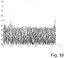
- FIG. 17a, 17b generate (which show plots without correcting the phase variations; Figures 18a, 18b , demonstrate Plots with correction of phase variations; Fig. 17a , 18a for the first module, 18a, 18b for the second module), from which the speed can also be derived comparatively precisely.
- a remaining phase noise which is much stronger on the cross path than in a primary radar response, is noticeable in the form of randomly distributed, small peaks. These are distributed over all speeds and (quasi) the same in the first and second module (but out of phase by 180 degrees).
- the method just described for reducing interference components, in particular phase noise has (in particular in the automotive sector) a number of advantages.
- an improved SNR (signal-to-noise ratio) and increased reliability can be achieved.
- the distance and speed vector of a target can be estimated with comparatively high accuracy, since additional estimated values are available and can be used.
- a (coherent) processing of a frequency shift caused by a Doppler effect can also take place without problems via a cross path.
- Phase information from a first radar module and a second radar module can thus be used to carry out a precise measurement of the surroundings. This enables SAR processing, in particular in an automotive radar application, to be implemented in order to generate a high-resolution image of the environment.
- An application as a phase monopole with both stations can serve to be able to estimate an azimuth angle very precisely. This estimate can also used in conjunction with existing angle information to further increase accuracy.
- pre-synchronization By feeding in an external, regulated clock, it could be recognized that a rough synchronization (pre-synchronization) is fundamentally possible, which would be conceivable, for example, via a CAN bus (of a motor vehicle). This can reduce the computational complexity of the method and can result in less error propagation.
- Reflections from complex objects can be recognized comparatively easily, possibly even if they do not go in the direction of an incident wave (bistatic radar principle).
- a combination of several radar modules enables a (significant) improvement in an estimate of an inherent movement of the moving object (vehicle), since the accuracy of the angle measurement significantly influences it.
- a combination of several radar modules in the elevation direction enables a significant improvement in an altitude estimate, in particular by means of interferometric SAR, that is to say an estimate of the altitude profile of a (complete) environment of a moving object (vehicle).
Applications Claiming Priority (4)
| Application Number | Priority Date | Filing Date | Title |
|---|---|---|---|
| DE102017104377 | 2017-03-02 | ||
| DE102017110063.6A DE102017110063A1 (de) | 2017-03-02 | 2017-05-10 | Verfahren und Vorrichtung zur Umfelderfassung |
| EP18708108.8A EP3589971A1 (fr) | 2017-03-02 | 2018-02-28 | Procédé et dispositif d'enregistrement de l'environnement |
| PCT/EP2018/054861 WO2018158281A1 (fr) | 2017-03-02 | 2018-02-28 | Procédé et dispositif d'enregistrement de l'environnement |
Related Parent Applications (2)
| Application Number | Title | Priority Date | Filing Date |
|---|---|---|---|
| EP18708108.8A Division-Into EP3589971A1 (fr) | 2017-03-02 | 2018-02-28 | Procédé et dispositif d'enregistrement de l'environnement |
| EP18708108.8A Division EP3589971A1 (fr) | 2017-03-02 | 2018-02-28 | Procédé et dispositif d'enregistrement de l'environnement |
Publications (1)
| Publication Number | Publication Date |
|---|---|
| EP3660537A1 true EP3660537A1 (fr) | 2020-06-03 |
Family
ID=63171074
Family Applications (2)
| Application Number | Title | Priority Date | Filing Date |
|---|---|---|---|
| EP18708108.8A Pending EP3589971A1 (fr) | 2017-03-02 | 2018-02-28 | Procédé et dispositif d'enregistrement de l'environnement |
| EP19209160.1A Pending EP3660537A1 (fr) | 2017-03-02 | 2018-02-28 | Procédé et dispositif de détection environnementale |
Family Applications Before (1)
| Application Number | Title | Priority Date | Filing Date |
|---|---|---|---|
| EP18708108.8A Pending EP3589971A1 (fr) | 2017-03-02 | 2018-02-28 | Procédé et dispositif d'enregistrement de l'environnement |
Country Status (7)
| Country | Link |
|---|---|
| US (1) | US11906655B2 (fr) |
| EP (2) | EP3589971A1 (fr) |
| JP (2) | JP2020509386A (fr) |
| KR (1) | KR102397235B1 (fr) |
| CN (1) | CN110622026B (fr) |
| DE (1) | DE102017110063A1 (fr) |
| WO (1) | WO2018158281A1 (fr) |
Families Citing this family (27)
| Publication number | Priority date | Publication date | Assignee | Title |
|---|---|---|---|---|
| DE102017110063A1 (de) | 2017-03-02 | 2018-09-06 | Friedrich-Alexander-Universität Erlangen-Nürnberg | Verfahren und Vorrichtung zur Umfelderfassung |
| JP7004520B2 (ja) * | 2017-07-05 | 2022-02-04 | 日本無線株式会社 | レーダ装置および高さ測定方法 |
| DE102017215561A1 (de) * | 2017-09-05 | 2019-03-07 | Robert Bosch Gmbh | FMCW-Radarsensor mit synchronisierten Hochfrequenzbausteinen |
| DE112019003435T5 (de) * | 2018-08-07 | 2021-04-01 | Murata Manufacturing Co., Ltd. | Radarvorrichtung |
| US11656335B2 (en) * | 2019-03-05 | 2023-05-23 | Rohde & Schwarz Gmbh & Co. Kg | System and method for detecting aircraft signatures |
| DE102019002662A1 (de) | 2019-04-10 | 2020-10-15 | Friedrich-Alexander-Universität Erlangen-Nürnberg | Verfahren zur Auswertung von Radarsystemen |
| JP7429054B2 (ja) | 2019-04-30 | 2024-02-07 | ツェンダー インク. | レーダデータを結合するためのシステムおよび方法 |
| CN110379178B (zh) * | 2019-07-25 | 2021-11-02 | 电子科技大学 | 基于毫米波雷达成像的无人驾驶汽车智能泊车方法 |
| RU2726188C1 (ru) * | 2019-08-21 | 2020-07-09 | Федеральное государственное казенное военное образовательное учреждение высшего образования "Военный учебно-научный центр Военно-воздушных сил "Военно-воздушная академия имени профессора Н.Е. Жуковского и Ю.А. Гагарина" (г. Воронеж) Министерства обороны Российской Федерации | Способ определения параметров частотно-кодированных сигналов в автокорреляционном приемнике |
| DE102019124120A1 (de) | 2019-09-09 | 2021-03-11 | Friedrich-Alexander-Universität Erlangen-Nürnberg | Radar-Verfahren sowie Radar-System |
| WO2021053640A1 (fr) * | 2019-09-20 | 2021-03-25 | University Of Kansas | Capture et remplissage sans échos parasites (deccaf) pour la compensation d'une variation d'encoche spectrale intra-cpi |
| DE102019126988A1 (de) * | 2019-10-08 | 2021-04-08 | Friedrich-Alexander-Universität Erlangen-Nürnberg | Verfahren zur Reduzierung von Störeinflüssen in einem Radar-System |
| DE102019128432A1 (de) * | 2019-10-22 | 2021-04-22 | Valeo Schalter Und Sensoren Gmbh | Verfahren zum Betreiben eines Radarsensors für ein Fahrzeug mit Kompensation von Störungen im Nahbereich, Recheneinrichtung sowie Radarsensor |
| CN111030683B (zh) * | 2019-12-31 | 2024-04-09 | 加特兰微电子科技(上海)有限公司 | 低通滤波器、锁相环以及雷达系统 |
| US11719786B2 (en) * | 2020-02-25 | 2023-08-08 | The United States Of America As Represented By The Secretary Of The Army | Asynchronous, coherent, radar transmitter-receiver system |
| CN113391257B (zh) * | 2020-03-13 | 2023-04-18 | 光宝科技新加坡私人有限公司 | 用于物件的角度估测的运算装置及物件的角度估测方法 |
| EP3883144B1 (fr) * | 2020-03-18 | 2022-12-07 | Airbus Defence and Space GmbH | Procédé de synchronisation de n uds de réseau sans fil et réseau de communication sans fil |
| US20210364622A1 (en) * | 2020-05-20 | 2021-11-25 | Infineon Technologies Ag | Processing radar signals |
| DE102020116236A1 (de) | 2020-06-19 | 2021-12-23 | Audi Aktiengesellschaft | Verfahren zur Ermittlung eines Geschwindigkeitsvektors eines Umfeldobjekts in einem Kraftfahrzeug und Kraftfahrzeug |
| DE102020123293A1 (de) | 2020-09-07 | 2022-03-10 | Friedrich-Alexander-Universität Erlangen-Nürnberg | Verfahren, Radarsystem und Fahrzeug zur Signalverarbeitung von Radarsignalen |
| US11762079B2 (en) * | 2020-09-30 | 2023-09-19 | Aurora Operations, Inc. | Distributed radar antenna array aperture |
| DE102021118076A1 (de) | 2021-02-08 | 2022-08-11 | Friedrich-Alexander-Universität Erlangen-Nürnberg, Körperschaft des öffentlichen Rechts | Radar-System sowie entsprechendes Verfahren |
| KR20230144035A (ko) | 2021-02-08 | 2023-10-13 | 지메오 게엠베하 | 레이더 시스템 및 대응하는 방법 |
| CN114722344B (zh) * | 2022-03-11 | 2023-10-20 | 中国电子科技集团公司第二十九研究所 | 基于相位补偿的高精度数据拼接方法 |
| DE102022131595A1 (de) * | 2022-03-14 | 2023-09-14 | Elmos Semiconductor Se | Verfahren und Vorrichtung zur Datenkommunikation in einem Fahrzeug zwischen einer Ansteuervorrichtung und mehreren Einheiten |
| DE102022120258A1 (de) | 2022-08-11 | 2024-02-22 | Bayerische Motoren Werke Aktiengesellschaft | Verfahren und Radareinrichtung zur radarbasierten Größeneinstufung von Objekten und entsprechend eingerichtetes Kraftfahrzeug |
| DE102022127669A1 (de) | 2022-10-20 | 2024-04-25 | Bayerische Motoren Werke Aktiengesellschaft | Verfahren und Vorrichtung zur Ermittlung der tangentialen Geschwindigkeit eines Objektes |
Citations (6)
| Publication number | Priority date | Publication date | Assignee | Title |
|---|---|---|---|---|
| US6317075B1 (en) | 1997-08-27 | 2001-11-13 | Siemens Aktiengesselschaft | FMCW sensor |
| DE10157931A1 (de) | 2001-11-26 | 2003-06-12 | Siemens Ag | Verfahren und Vorrichtungen zur Synchronisation von Funkstationen und zeitsynchrones Funkbussystem |
| DE102008010536A1 (de) | 2008-02-22 | 2009-08-27 | Symeo Gmbh | Schaltungsanordnung und Verfahren zur Synchronisation von Uhren in einem Netz |
| DE102009030076A1 (de) | 2009-06-23 | 2010-12-30 | Symeo Gmbh | Abbildungsverfahren mittels synthetischer Apertur, Verfahren zur Bestimmung einer Relativgeschwindigkeit zwischen einem wellenbasierten Sensor und einem Objekt bzw. Vorrichtung zur Durchführung der Verfahren |
| DE102014104273A1 (de) | 2014-03-26 | 2015-10-01 | Friedrich-Alexander-Universität Erlangen-Nürnberg | Verfahren in einem Radarsystem, Radarsystem bzw. Vorrichtung eines Radarsystems |
| DE102015121724A1 (de) | 2015-12-14 | 2017-06-14 | Symeo Gmbh | System und Verfahren mit zumindest drei Signale empfangenden Stationen |
Family Cites Families (28)
| Publication number | Priority date | Publication date | Assignee | Title |
|---|---|---|---|---|
| DE4037725A1 (de) * | 1990-11-27 | 1992-06-11 | Deutsche Forsch Luft Raumfahrt | Verfahren zur digitalen generierung von sar-bildern und einrichtung zu dessen durchfuehrung |
| US5557196A (en) * | 1993-08-25 | 1996-09-17 | Advantest Corporation | Jitter analyzer |
| WO1997022890A1 (fr) * | 1995-12-19 | 1997-06-26 | Siemens Schweiz Ag | Procede et appareil radar monopulse en amplitude ou en phase pour reperer des objets volants |
| IL127650A0 (en) * | 1996-06-28 | 1999-10-28 | Milkovich Systems Engineering | Improved fast fourier transform processor |
| FR2760536B1 (fr) * | 1997-03-04 | 1999-05-28 | Thomson Csf | Procede et dispositif de detection radar a modulation de frequence a onde continue presentant une levee d'ambiguite entre la distance et la vitesse |
| US7076227B1 (en) * | 1998-12-03 | 2006-07-11 | Apex/Eclipse Systems, Inc. | Receiving system with improved directivity and signal to noise ratio |
| JP4509297B2 (ja) * | 2000-04-26 | 2010-07-21 | 三菱電機株式会社 | スペクトル拡散受信装置 |
| WO2005008281A1 (fr) * | 2003-07-19 | 2005-01-27 | Gamma Remote Sensing Research And Consulting Ag | Procede permettant d'ameliorer les signatures interferometriques de diffuseurs ponctuels coherents |
| US7821422B2 (en) * | 2003-08-18 | 2010-10-26 | Light Vision Systems, Inc. | Traffic light signal system using radar-based target detection and tracking |
| US7183969B2 (en) | 2004-12-22 | 2007-02-27 | Raytheon Company | System and technique for calibrating radar arrays |
| EP1869492B1 (fr) | 2005-04-04 | 2013-04-24 | Raytheon Company | Systeme et procede permettant de combiner de façon coherente une pluralite de radars |
| WO2007098011A2 (fr) * | 2006-02-17 | 2007-08-30 | Regents Of The University Of Minnesota | Résonance magnétique de haute résolution |
| JP2007225442A (ja) | 2006-02-23 | 2007-09-06 | Mitsubishi Electric Corp | レーダ装置 |
| JP4980129B2 (ja) | 2007-04-26 | 2012-07-18 | 三菱電機株式会社 | 画像レーダ装置 |
| US8477888B2 (en) * | 2008-06-24 | 2013-07-02 | Qualcomm Incorporated | Phase-noise resilient generation of a channel quality indicator |
| DE102009030075A1 (de) * | 2009-06-23 | 2010-12-30 | Symeo Gmbh | Vorrichtung und Abbildungsverfahren mit synthetischer Apertur zum Bestimmen eines Einfallwinkels und/oder einer Entfernung |
| US8600606B2 (en) * | 2010-02-11 | 2013-12-03 | GM Global Technology Operations LLC | Vehicle safety systems and methods |
| WO2011150242A1 (fr) * | 2010-05-28 | 2011-12-01 | Optical Air Data Systems, Llc | Procédé et appareil destinés à un télémètre laser cohérent à impulsion |
| US10051643B2 (en) * | 2011-08-17 | 2018-08-14 | Skyline Partners Technology Llc | Radio with interference measurement during a blanking interval |
| JP6031267B2 (ja) * | 2012-06-21 | 2016-11-24 | 古野電気株式会社 | 干渉検出装置、干渉除去器、レーダ装置、干渉検出方法および干渉検出用プログラム |
| EP3033634B1 (fr) | 2013-08-14 | 2017-05-31 | IEE International Electronics & Engineering S.A. | Détection radar d'occupation de véhicule |
| CN103954944A (zh) * | 2014-05-14 | 2014-07-30 | 武汉大学 | 一种高频地波雷达射频干扰抑制的方法 |
| US9057785B1 (en) * | 2014-05-29 | 2015-06-16 | Robert W. Lee | Radar operation with increased doppler capability |
| US10168425B2 (en) | 2014-07-03 | 2019-01-01 | GM Global Technology Operations LLC | Centralized vehicle radar methods and systems |
| CN107004174B (zh) | 2014-10-23 | 2021-09-03 | 东南水务公司 | 用于监视一个或更多个设施处的活动的系统和方法 |
| US10101438B2 (en) | 2015-04-15 | 2018-10-16 | Texas Instruments Incorporated | Noise mitigation in radar systems |
| EP3400458B1 (fr) | 2016-01-04 | 2021-10-13 | Symeo GmbH | Procédé et système pour la réduction de perturbation par bruit de phase dans un système radar |
| DE102017110063A1 (de) | 2017-03-02 | 2018-09-06 | Friedrich-Alexander-Universität Erlangen-Nürnberg | Verfahren und Vorrichtung zur Umfelderfassung |
-
2017
- 2017-05-10 DE DE102017110063.6A patent/DE102017110063A1/de active Pending
-
2018
- 2018-02-28 US US16/490,476 patent/US11906655B2/en active Active
- 2018-02-28 EP EP18708108.8A patent/EP3589971A1/fr active Pending
- 2018-02-28 EP EP19209160.1A patent/EP3660537A1/fr active Pending
- 2018-02-28 KR KR1020197029132A patent/KR102397235B1/ko active IP Right Grant
- 2018-02-28 CN CN201880028424.5A patent/CN110622026B/zh active Active
- 2018-02-28 JP JP2019547513A patent/JP2020509386A/ja active Pending
- 2018-02-28 WO PCT/EP2018/054861 patent/WO2018158281A1/fr unknown
-
2024
- 2024-01-25 JP JP2024009482A patent/JP2024042029A/ja active Pending
Patent Citations (7)
| Publication number | Priority date | Publication date | Assignee | Title |
|---|---|---|---|---|
| US6317075B1 (en) | 1997-08-27 | 2001-11-13 | Siemens Aktiengesselschaft | FMCW sensor |
| DE10157931A1 (de) | 2001-11-26 | 2003-06-12 | Siemens Ag | Verfahren und Vorrichtungen zur Synchronisation von Funkstationen und zeitsynchrones Funkbussystem |
| US7940743B2 (en) | 2001-11-26 | 2011-05-10 | Symeo Gmbh | Method and device for the synchronization of radio stations and a time-synchronous radio bus system |
| DE102008010536A1 (de) | 2008-02-22 | 2009-08-27 | Symeo Gmbh | Schaltungsanordnung und Verfahren zur Synchronisation von Uhren in einem Netz |
| DE102009030076A1 (de) | 2009-06-23 | 2010-12-30 | Symeo Gmbh | Abbildungsverfahren mittels synthetischer Apertur, Verfahren zur Bestimmung einer Relativgeschwindigkeit zwischen einem wellenbasierten Sensor und einem Objekt bzw. Vorrichtung zur Durchführung der Verfahren |
| DE102014104273A1 (de) | 2014-03-26 | 2015-10-01 | Friedrich-Alexander-Universität Erlangen-Nürnberg | Verfahren in einem Radarsystem, Radarsystem bzw. Vorrichtung eines Radarsystems |
| DE102015121724A1 (de) | 2015-12-14 | 2017-06-14 | Symeo Gmbh | System und Verfahren mit zumindest drei Signale empfangenden Stationen |
Non-Patent Citations (8)
| Title |
|---|
| D. ZANKL ET AL.: "BLASTDAR - A Large Radar Sensor Array System for Blast Furnace Burden Surface Imaging", IEEE SENSOR JOUNAL, vol. 15, no. 10, October 2015 (2015-10-01), XP011666994, DOI: 10.1109/JSEN.2015.2445494 |
| F. ALIG. BAUERM. VOSSIEK: "A Rotating Synthetic Aperture Radar Imaging Concept for Robot Navigation", IEEE TRANSACTIONS ON MICROWAVE THEORY AND TECHNIQUES, vol. 62, no. 7, July 2014 (2014-07-01), XP011552510, DOI: 10.1109/TMTT.2014.2323013 |
| FRISCHEN ANDREAS ET AL: "A Cooperative MIMO Radar Network Using Highly Integrated FMCW Radar Sensors", IEEE TRANSACTIONS ON MICROWAVE THEORY AND TECHNIQUES, PLENUM, USA, vol. 65, no. 4, 1 February 2017 (2017-02-01), pages 1355 - 1366, XP011644690, ISSN: 0018-9480, [retrieved on 20170403], DOI: 10.1109/TMTT.2016.2647701 * |
| J. CAPON: "High-Resolution Frequency-Wavenumber Spectrum Analysis", PROCEEDINGS OF THE IEEE, vol. 57, no. 8, August 1969 (1969-08-01), XP008025691 |
| KONG SUNWOO ET AL: "Wireless Cooperative Synchronization of Coherent UWB MIMO Radar", IEEE TRANSACTIONS ON MICROWAVE THEORY AND TECHNIQUES, PLENUM, USA, vol. 62, no. 1, 1 January 2014 (2014-01-01), pages 154 - 165, XP011536024, ISSN: 0018-9480, [retrieved on 20140101], DOI: 10.1109/TMTT.2013.2291541 * |
| M. A. RICHARDS: "A Beginner's Guide to Interferometric SAR Concepts and Signal Processing", IEEE AEROSPACE AND ELECTRONIC SYSTEMS MAGAZINE, vol. 22, no. 9, 2007, pages 5 - 29, XP011194384, DOI: 10.1109/MAES.2007.4350281 |
| R. SCHMIDT: "Multiple Emitter - Location and Signal - Parameter Estimation", IEEE TRANSACTIONS ON ANTENNAS AND PROPAGATION, vol. AP-34, no. 3, March 1986 (1986-03-01), XP000644956, DOI: 10.1109/TAP.1986.1143830 |
| S. ROEHRP. GULDENM. VOSSIEK: "Precise Distance and Velocity Measurement for Real Time Locating in Multipath Environments Using a Frequency-Modulated Continuous-Wave Secondary Radar Approach", IEEE TRANS. MICROW. THEORY TECH., vol. 56, no. 10, October 2008 (2008-10-01), pages 2329 - 2339, XP011234437, DOI: 10.1109/TMTT.2008.2003137 |
Also Published As
| Publication number | Publication date |
|---|---|
| EP3589971A1 (fr) | 2020-01-08 |
| KR102397235B1 (ko) | 2022-05-11 |
| US20210405183A1 (en) | 2021-12-30 |
| CN110622026B (zh) | 2024-03-08 |
| KR20190137801A (ko) | 2019-12-11 |
| DE102017110063A1 (de) | 2018-09-06 |
| CN110622026A (zh) | 2019-12-27 |
| US11906655B2 (en) | 2024-02-20 |
| JP2020509386A (ja) | 2020-03-26 |
| JP2024042029A (ja) | 2024-03-27 |
| WO2018158281A1 (fr) | 2018-09-07 |
Similar Documents
| Publication | Publication Date | Title |
|---|---|---|
| EP3660537A1 (fr) | Procédé et dispositif de détection environnementale | |
| EP3400458B1 (fr) | Procédé et système pour la réduction de perturbation par bruit de phase dans un système radar | |
| DE102018127947B3 (de) | Mimo fmcw radarsystem | |
| EP3377915B1 (fr) | Système radar avec transmission en série et réception en parallèle imbriquée | |
| EP3123199B1 (fr) | Procédé mis en oeuvre dans un système de radar, système de radar et dispositif d'un système de radar | |
| EP3161514B1 (fr) | Procédé de mesure d'un mimo radar | |
| EP3014297B1 (fr) | Détecteur à radar fmcw à résolution angulaire | |
| EP3161513B1 (fr) | Procédé de mésure de radar avec des zones de vision différentes | |
| DE102018108648B4 (de) | Fmcw radar mit störsignalunterdrückung | |
| DE102020111533A1 (de) | Mimo-radar-vorrichtungen und mimo-radar-verfahren | |
| DE102018100632A1 (de) | Radar-Verfahren und -System zur Bestimmung der Winkellage, des Ortes und/oder der, insbesondere vektoriellen, Geschwindigkeit eines Zieles | |
| EP2725382B1 (fr) | Radar à ouverture synthétique pour la prise de vue et la détection de cible mobile simultanées | |
| DE102019106529A1 (de) | Fmcw radar mit störsignalunterdrückung mittels künstlichem neuronalen netz | |
| DE102018132745B4 (de) | Fmcw radar mit störsignalunterdrückung im zeitbereich | |
| EP3803454B1 (fr) | Procédé radar à ouverture synthetique et dispositif radar à ouverture synthetique | |
| EP2417475A2 (fr) | Système radar doté d'agencements et procédé pour découpler des signaux d'émission et de réception ainsi que pour annuler des rayonnements parasites | |
| EP2294446A2 (fr) | Système radar à capacité de mesure en élévation | |
| DE102012021973A1 (de) | Verfahren zum Betreiben eines Radarsensors eines Kraftfahrzeugs, Fahrerassistenzeinrichtung und Kraftfahrzeug | |
| EP3470874A1 (fr) | Procédé et système radar permettant de déterminer la position angulaire, l'emplacement et / ou la vitesse d'une cible, en particulier la vitesse vectorielle | |
| DE102012024998A1 (de) | Verfahren zum Bestimmen einer lateralen Geschwindigkeit eines Zielobjekts relativ zu einem Kraftfahrzeug mit Hilfe eines Radarsensors, Fahrerassistenzsystem und Kraftfahrzeug | |
| DE102014218092A1 (de) | Erstellen eines Abbilds der Umgebung eines Kraftfahrzeugs und Bestimmen der relativen Geschwindigkeit zwischen dem Kraftfahrzeug und Objekten in der Umgebung | |
| WO2021047844A1 (fr) | Procédé radar et système radar | |
| DE102017110404A1 (de) | Verfahren und Vorrichtung zur Kompensation von Störeinflüssen | |
| DE102008011889A1 (de) | Digitale Strahlformung mit frequenzmodulierten Signalen | |
| WO2018158173A1 (fr) | Système radar et procédé pour faire fonctionner un système radar |
Legal Events
| Date | Code | Title | Description |
|---|---|---|---|
| PUAI | Public reference made under article 153(3) epc to a published international application that has entered the european phase |
Free format text: ORIGINAL CODE: 0009012 |
|
| STAA | Information on the status of an ep patent application or granted ep patent |
Free format text: STATUS: THE APPLICATION HAS BEEN PUBLISHED |
|
| AC | Divisional application: reference to earlier application |
Ref document number: 3589971 Country of ref document: EP Kind code of ref document: P |
|
| AK | Designated contracting states |
Kind code of ref document: A1 Designated state(s): AL AT BE BG CH CY CZ DE DK EE ES FI FR GB GR HR HU IE IS IT LI LT LU LV MC MK MT NL NO PL PT RO RS SE SI SK SM TR |
|
| AX | Request for extension of the european patent |
Extension state: BA ME |
|
| STAA | Information on the status of an ep patent application or granted ep patent |
Free format text: STATUS: REQUEST FOR EXAMINATION WAS MADE |
|
| 17P | Request for examination filed |
Effective date: 20201130 |
|
| RBV | Designated contracting states (corrected) |
Designated state(s): AL AT BE BG CH CY CZ DE DK EE ES FI FR GB GR HR HU IE IS IT LI LT LU LV MC MK MT NL NO PL PT RO RS SE SI SK SM TR |
|
| RAP3 | Party data changed (applicant data changed or rights of an application transferred) |
Owner name: SYMEO GMBH Owner name: FRIEDRICH-ALEXANDER-UNIVERSITAET ERLANGEN-NUERNBERG |
|
| RAP1 | Party data changed (applicant data changed or rights of an application transferred) |
Owner name: SYMEO GMBH |
|
| STAA | Information on the status of an ep patent application or granted ep patent |
Free format text: STATUS: EXAMINATION IS IN PROGRESS |
|
| 17Q | First examination report despatched |
Effective date: 20221129 |