EP3660302B1 - Yaw system for a wind turbine - Google Patents
Yaw system for a wind turbine Download PDFInfo
- Publication number
- EP3660302B1 EP3660302B1 EP18382867.2A EP18382867A EP3660302B1 EP 3660302 B1 EP3660302 B1 EP 3660302B1 EP 18382867 A EP18382867 A EP 18382867A EP 3660302 B1 EP3660302 B1 EP 3660302B1
- Authority
- EP
- European Patent Office
- Prior art keywords
- gliding
- bearing component
- bearing
- nacelle
- axial
- Prior art date
- Legal status (The legal status is an assumption and is not a legal conclusion. Google has not performed a legal analysis and makes no representation as to the accuracy of the status listed.)
- Active
Links
Images


Classifications
-
- F—MECHANICAL ENGINEERING; LIGHTING; HEATING; WEAPONS; BLASTING
- F03—MACHINES OR ENGINES FOR LIQUIDS; WIND, SPRING, OR WEIGHT MOTORS; PRODUCING MECHANICAL POWER OR A REACTIVE PROPULSIVE THRUST, NOT OTHERWISE PROVIDED FOR
- F03D—WIND MOTORS
- F03D7/00—Controlling wind motors
- F03D7/02—Controlling wind motors the wind motors having rotation axis substantially parallel to the air flow entering the rotor
- F03D7/0204—Controlling wind motors the wind motors having rotation axis substantially parallel to the air flow entering the rotor for orientation in relation to wind direction
-
- F—MECHANICAL ENGINEERING; LIGHTING; HEATING; WEAPONS; BLASTING
- F03—MACHINES OR ENGINES FOR LIQUIDS; WIND, SPRING, OR WEIGHT MOTORS; PRODUCING MECHANICAL POWER OR A REACTIVE PROPULSIVE THRUST, NOT OTHERWISE PROVIDED FOR
- F03D—WIND MOTORS
- F03D80/00—Details, components or accessories not provided for in groups F03D1/00 - F03D17/00
- F03D80/50—Maintenance or repair
-
- F—MECHANICAL ENGINEERING; LIGHTING; HEATING; WEAPONS; BLASTING
- F03—MACHINES OR ENGINES FOR LIQUIDS; WIND, SPRING, OR WEIGHT MOTORS; PRODUCING MECHANICAL POWER OR A REACTIVE PROPULSIVE THRUST, NOT OTHERWISE PROVIDED FOR
- F03D—WIND MOTORS
- F03D1/00—Wind motors with rotation axis substantially parallel to the air flow entering the rotor
- F03D1/06—Rotors
- F03D1/065—Rotors characterised by their construction elements
- F03D1/0675—Rotors characterised by their construction elements of the blades
-
- F—MECHANICAL ENGINEERING; LIGHTING; HEATING; WEAPONS; BLASTING
- F03—MACHINES OR ENGINES FOR LIQUIDS; WIND, SPRING, OR WEIGHT MOTORS; PRODUCING MECHANICAL POWER OR A REACTIVE PROPULSIVE THRUST, NOT OTHERWISE PROVIDED FOR
- F03D—WIND MOTORS
- F03D13/00—Assembly, mounting or commissioning of wind motors; Arrangements specially adapted for transporting wind motor components
- F03D13/20—Arrangements for mounting or supporting wind motors; Masts or towers for wind motors
-
- F—MECHANICAL ENGINEERING; LIGHTING; HEATING; WEAPONS; BLASTING
- F03—MACHINES OR ENGINES FOR LIQUIDS; WIND, SPRING, OR WEIGHT MOTORS; PRODUCING MECHANICAL POWER OR A REACTIVE PROPULSIVE THRUST, NOT OTHERWISE PROVIDED FOR
- F03D—WIND MOTORS
- F03D80/00—Details, components or accessories not provided for in groups F03D1/00 - F03D17/00
- F03D80/70—Bearing or lubricating arrangements
-
- F—MECHANICAL ENGINEERING; LIGHTING; HEATING; WEAPONS; BLASTING
- F16—ENGINEERING ELEMENTS AND UNITS; GENERAL MEASURES FOR PRODUCING AND MAINTAINING EFFECTIVE FUNCTIONING OF MACHINES OR INSTALLATIONS; THERMAL INSULATION IN GENERAL
- F16C—SHAFTS; FLEXIBLE SHAFTS; ELEMENTS OR CRANKSHAFT MECHANISMS; ROTARY BODIES OTHER THAN GEARING ELEMENTS; BEARINGS
- F16C17/00—Sliding-contact bearings for exclusively rotary movement
- F16C17/10—Sliding-contact bearings for exclusively rotary movement for both radial and axial load
-
- F—MECHANICAL ENGINEERING; LIGHTING; HEATING; WEAPONS; BLASTING
- F05—INDEXING SCHEMES RELATING TO ENGINES OR PUMPS IN VARIOUS SUBCLASSES OF CLASSES F01-F04
- F05B—INDEXING SCHEME RELATING TO WIND, SPRING, WEIGHT, INERTIA OR LIKE MOTORS, TO MACHINES OR ENGINES FOR LIQUIDS COVERED BY SUBCLASSES F03B, F03D AND F03G
- F05B2240/00—Components
- F05B2240/50—Bearings
-
- Y—GENERAL TAGGING OF NEW TECHNOLOGICAL DEVELOPMENTS; GENERAL TAGGING OF CROSS-SECTIONAL TECHNOLOGIES SPANNING OVER SEVERAL SECTIONS OF THE IPC; TECHNICAL SUBJECTS COVERED BY FORMER USPC CROSS-REFERENCE ART COLLECTIONS [XRACs] AND DIGESTS
- Y02—TECHNOLOGIES OR APPLICATIONS FOR MITIGATION OR ADAPTATION AGAINST CLIMATE CHANGE
- Y02E—REDUCTION OF GREENHOUSE GAS [GHG] EMISSIONS, RELATED TO ENERGY GENERATION, TRANSMISSION OR DISTRIBUTION
- Y02E10/00—Energy generation through renewable energy sources
- Y02E10/70—Wind energy
- Y02E10/72—Wind turbines with rotation axis in wind direction
-
- Y—GENERAL TAGGING OF NEW TECHNOLOGICAL DEVELOPMENTS; GENERAL TAGGING OF CROSS-SECTIONAL TECHNOLOGIES SPANNING OVER SEVERAL SECTIONS OF THE IPC; TECHNICAL SUBJECTS COVERED BY FORMER USPC CROSS-REFERENCE ART COLLECTIONS [XRACs] AND DIGESTS
- Y02—TECHNOLOGIES OR APPLICATIONS FOR MITIGATION OR ADAPTATION AGAINST CLIMATE CHANGE
- Y02E—REDUCTION OF GREENHOUSE GAS [GHG] EMISSIONS, RELATED TO ENERGY GENERATION, TRANSMISSION OR DISTRIBUTION
- Y02E10/00—Energy generation through renewable energy sources
- Y02E10/70—Wind energy
- Y02E10/728—Onshore wind turbines
Definitions
- the present disclosure relates to gliding yaw bearings for wind turbines, wind turbines comprising such gliding yaw bearings and methods for removing a gliding pad of a gliding yaw bearing.
- Wind turbines are commonly used to supply electricity into the electrical grid.
- Wind turbines of this kind generally comprise a tower and a rotor arranged on the tower.
- the rotor which typically comprises a hub and a plurality of blades, is set into rotation under the influence of the wind on the blades. Said rotation generates a torque that is normally transmitted through a rotor shaft to a generator, either directly (“directly driven”) or through the use of a gearbox. This way, the generator produces electricity which can be supplied to the electrical grid.
- Most wind turbines comprise a yaw system used for orienting the rotor of the wind turbine in the prevailing wind direction. Normally, when the rotor is aligned with the wind direction, the yaw system maintains the position by means of brakes (e.g. hydraulic brake calipers and/or electro-brakes of the yaw motors). When the rotor is misaligned from the wind direction the yaw system rotates the nacelle to reach an appropriate alignment with the wind.
- brakes e.g. hydraulic brake calipers and/or electro-brakes of the yaw motors
- the yaw system normally performs this rotation of the nacelle by means of a yaw drive that includes a plurality of (electric or hydraulic) motors with suitable gearboxes for driving gears (pinions) that mesh with an annular gear or gear ring attached to the nacelle or to the wind turbine tower.
- the nacelle can thus be rotated around the tower's longitudinal axis in or out of the wind direction.
- the rotatable connection between the wind turbine tower and the nacelle is called a yaw bearing.
- the yaw bearing can be of the roller or gliding type.
- Gliding yaw bearings or sliding yaw bearings may be used in large wind turbines because they are cheaper than roller yaw bearings and are able to withstand high loads in axial and radial directions.
- Gliding or sliding yaw bearings may include an annular gear or gear ring configured to be fixed to the tower wherein the frame of the nacelle may rest and slide in its yawing movement.
- Lubrication e.g. oil or grease, may be applied between the annular gear and the frame of the nacelle for allowing the frame to rotate with respect to the annular gear. Lubrication reduces the friction between the annular gear and the frame of the nacelle and avoids the wear of the annular gear and/or the frame.
- the gliding yaw bearings usually comprise top axial gliding pads arranged between the upper surfaces of the annular gear and the frame, bottom axial gliding pads arranged between the bottom surfaces of the annular gear and the frame and radial gliding pads arranged between the radial surfaces of the annular gear and the frame. These pads are attached directly or indirectly to the main support of the nacelle.
- gliding pads generally suffer from wear, in particular in heavy wind turbines, e.g. offshore wind turbines.
- the sliding or gliding pads may thus need to be periodically repaired or replaced.
- replacing these pads is generally very complex and costly.
- the bottom axial gliding pads and the radial gliding pads may be attached to brackets connected to the frame of the nacelle. Disconnecting these brackets from the frame allows facilitating the removal of the bottom axial gliding pads and the radial gliding pads from the frame. However, in order to remove the top axial gliding pads, an extra operation may further be required.
- the present disclosure provides examples of systems and methods that at least partially resolve some of the aforementioned disadvantages.
- a method according to claim 1 for removing a gliding pad of a gliding yaw bearing of a wind turbine comprises selecting a gliding pad to be removed; rotating a nacelle that is rotatably mounted on a tower to a removal position in which a front side of the nacelle at which a rotor is arranged is positioned substantially diametrically opposite to the selected gliding pad, such that the pressure exerted on the selected gliding pad is released and then removing the selected gliding pad.
- the rotation of the nacelle may allow reducing the pressure exerted on the selected gliding yaw to be removed.
- Removing a gliding pad may be simplified since no external cranes or internal lifting devices may be necessary. Cost and time for replacing a gliding pad may thus be reduced. Maintenance costs of wind turbines may accordingly be reduced.
- a gliding yaw bearing for a wind turbine.
- the gliding yaw bearing comprises a first bearing component configured to be coupled to a tower of a wind turbine and a second bearing component configured to be coupled to a nacelle of a wind turbine.
- the first bearing component is configured to rotate with respect to the second bearing component.
- the gliding yaw bearing further comprises one or more axial gliding pads arranged between the first and the second bearing components.
- the gliding yaw bearing comprises a cut-out for accessing at least one axial gliding pad of the one or more axial gliding pads.
- the gliding pads may be easily removed through the cut-out.
- the pressure exerted by the first and the second bearing component on at least one axial gliding pad in the region of the cut-out is released.
- a gliding yaw bearing for a wind turbine having receptacles for receiving gliding pads.
- the gliding yaw bearing comprises a first bearing component configured to be coupled to a tower of a wind turbine and a second bearing component configured to be coupled to a nacelle of a wind turbine.
- the first bearing component comprises one or more receptacles and is configured to rotate with respect to the second bearing component.
- the gliding yaw bearing further comprises one or more axial gliding pads arranged between the first and the second bearing components, wherein the one or more axial gliding pads are fitted in the one or more receptacles.
- the axial gliding pads may be easily coupled to the first bearing component.
- the receptacles may also help holding the gliding pad in a correct position.
- loads acting on the axial gliding pads may be more uniformly distributed as the axial gliding pads are mounted on the first bearing component.
- Loads acting on each of the axial gliding pads may vary with the orientation of the nacelle. As the nacelle may be oriented towards the wind direction and the pads are associated with tower, the most stressed pads may vary according to the orientation of the nacelle. Accordingly, wear of the axial gliding pads may also be more uniformly distributed. Maintenance operations involving replacing axial gliding pads may thus be reduced.
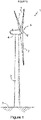
- Figure 1 illustrates a perspective view of one example of a wind turbine 1.
- the wind turbine 1 includes a tower 2 extending from a support surface 3, a nacelle 4 mounted on the tower 2, and a rotor 5 coupled to the nacelle 4.
- the rotor 5 includes a rotatable hub 6 and at least one rotor blade 7 coupled to and extending outwardly from the hub 6.
- the rotor 5 includes three rotor blades 7.
- the rotor 5 may include more or less than three rotor blades 7.
- Each rotor blade 7 may be spaced from the hub 6 to facilitate rotating the rotor 5 to enable kinetic energy to be transferred from the wind into usable mechanical energy, and subsequently, electrical energy.
- the hub 6 may be rotatably coupled to an electric generator 10 ( Figure 2 ) positioned within the nacelle 4 or forming part of the nacelle to permit electrical energy to be produced.
- the rotation of the rotor may be directly transmitted, e.g. in direct drive wind turbines, or through the use of a gearbox to a generator.
- FIG. 2 illustrates a simplified, internal view of one example of a nacelle 4 of a direct drive wind turbine 1.
- the generator 10 may be disposed within the nacelle 4 or between the nacelle 4 and the rotor 5.
- the generator 10 may be coupled to the rotor 5 of the wind turbine 1 for generating electrical power from the rotational energy generated by the rotor 5.
- the rotor 5 of the wind turbine may include a hub 6 coupled to a rotor 9 of a generator 10 for rotation therewith. The rotation of the hub 6 may thus drive the rotor 12 of the generator 10.
- the wind turbine rotor 5 may be rotatably mounted on a support frame 9 through two rotor bearings 8 at a coupling region or a front side.
- the support frame 9 may not extend through the hub 6 and therefore the rotor may be supported by a single rotor bearing 8, commonly called as the main bearing.
- the generator 10 may comprise a rotor 12 and a stator 13.
- the stator may be rigidly mounted on the support frame 9.
- the rotor may be rotatably mounted on the stator through a generator bearing 14 so that the rotor may rotate with respect to the stator around an axis.
- the generator 10 may be electrically coupled to the converter.
- the wind turbine converter may adapt the output electrical power of the generator to the requirements of the electrical grid.
- the converter may be placed inside the nacelle 4; however, in other examples it may be placed in other locations of the wind turbine.
- the rotor 5 of the wind turbine and the generator 10 may be supported by a bedplate or a support frame 9 positioned atop the wind turbine tower 2.
- the nacelle 4 is rotatably coupled to the tower 2 through a yaw system 20.
- the yaw system comprises a yaw bearing (not visible in Figure 2 ) having two bearing components configured to rotate with respect to the other.
- the tower 2 is coupled to a first bearing component and the nacelle 4, e.g. the bedplate or support frame 9, is coupled to the second bearing component.
- FIG. 3 illustrates an isometric view of a yaw system comprising a gliding yaw bearing according to one example.
- the yaw system 20 comprises a gliding yaw bearing 30 having a first bearing component 31 coupled to the tower 2 and a second bearing component 32 coupled to a nacelle 4.
- the second bearing component 32 may be coupled or form part of the support frame 9 of the nacelle.
- the first bearing component 31 is configured to rotate with respect to the second bearing component 32.
- the gliding yaw bearing 30 comprises one or more axial gliding pads (not visible in Figure 3 ) arranged between the first bearing component 31 and the second bearing component 32 for reducing the friction between them.
- the first and the second bearing components exert pressure on the one or more axial gliding pads.
- the axial gliding pads may thus be clamped between the bearing components.
- the gliding pads may be coupled to the first bearing component.
- the first bearing component may comprise receptacles (not visible in Figure 3 , but discussed later with respect to Figure 9 ) in which the gliding pads may be fitted.
- the receptacles may be configured to receive the axial gliding pads. A connection between the gliding pads and the first bearing component may thus be established.
- each one of the gliding pads may be coupled with one different receptacle.
- the first bearing component 31 comprises a gliding plate or gliding track or a gliding disk.
- the second bearing component 32 of this example comprises a bearing guide or a guiding pad assembly partially enclosing the gliding plate. A portion of the second bearing component 32 may thus partially enclose a portion of the first bearing component 31.
- the first and second bearing may comprise a top axial gliding surface, a bottom axial gliding surface and a radial gliding surface.
- the top and the bottom axial gliding surface and the radial gliding surface of the second bearing component in this example substantially define a C-shape.
- the first bearing component, i.e. the gliding plate is arranged between these gliding surfaces of the second bearing component, i.e. the guiding pad assembly.
- the guiding pad assembly may thus guide the rotation of the gliding plate.
- the guiding pad assembly is placed radially inwards of the gliding plate.
- the gliding plate may be placed radially inwards of the guiding pad assembly.
- the second bearing component 32 may comprise a portion of the support frame 9 or may be coupled to the support frame.
- the first bearing component 31 may comprise a portion of a tower 2, e.g. a flange, or may be coupled to the tower.
- the first bearing component may comprise a portion of a tower adapter, the tower adapter extending along a vertical axis and configured to be fixedly coupled to a top portion of a wind turbine tower.
- the yaw system may comprise an annular gear 21 coupled to the tower 2 and a plurality of yaw drives 22 coupled to the support frame 9.
- the yaw drives 22 comprise a motor 23, a gearbox 24 and a pinion 25 for meshing with the annular gear 21.
- the rotation of the gearbox can rotate the pinion with respect to annular gear 21.
- first bearing component 31 comprises the annular gear 21. The first bearing component 31 can therefore rotate with respect to the second bearing component 32.
- the annular gear 21 may comprise a plurality of teeth which engage with the teeth of the pinions 25 of the yaw drives.
- the yaw drives 22 and the annular gear 21 are placed outside the external diameter of the tower.
- the teeth of the annular gear are outwardly orientated.
- the annular gear 21 may be connected, e.g. welded or fastened, to the guiding plate of the first bearing component.
- the annular gear 21 and the guiding plate of the first bearing component may form an integral part.
- the yaw system may also comprise braking units or brake calipers (not visible in Figure 3 ) for braking or blocking the rotation of the first bearing component 31 with respect to the second bearing component 32.
- the braking units may thus block the rotation of the nacelle with respect to the tower.
- FIG. 4 schematically illustrates a gliding yaw bearing according to a further example.
- the gliding yaw bearing 30 in this example comprises a first bearing component 31 coupled to the tower and a second bearing component 32 coupled to the nacelle 4.
- the first bearing component 31 is configured to rotate with respect to the second bearing component 32 around the rotational axis 19.
- Coupling the second bearing component to the nacelle may include connecting, e.g. bolting, the second bearing component to the support frame 9 of the nacelle or forming an integral part of the support frame 9.
- the second bearing component comprises a bracket 33 bolted to a portion of the support frame.
- the bracket 33 and the portion of the support frame form a gliding pad assembly partially enclosing the first bearing component.
- the bracket may be formed from several pieces joined together, e.g. welded or bolted.
- the first bearing 31 component is bolted to a flange 91 of the top portion of the tower 2.
- the first bearing component may be integrally formed with the tower.
- the annular gear 21 is formed integrally with first bearing component.
- the teeth of the annular gear are arranged outside the diameter defined by the tower and may be outwardly oriented.
- the annular gear 21 may be connected to the first bearing component or to the tower 2.
- Yaw drives with a pinion may engage the annular gear 21 coupled (directly or indirectly) to the tower 2.
- the gliding yaw bearing further comprises one or more axial gliding pads 51 arranged between the first bearing component 31 and the second bearing component 32.
- the axial gliding pads 51 are coupled to the first bearing component.
- the first bearing component 31 may comprise receptacles 34 for receiving the axial gliding pads.
- the axial gliding pads 51 may be fitted in the receptacles 34. The axial gliding pads may thus be retained by the receptacles.
- coupling the axial gliding pads to the first bearing component may comprise bolting or gluing or otherwise adhering the axial gliding pads to the first bearing component.
- the axial gliding pads may be arranged in the fixed part of the yaw bearing.
- the nacelle 4 of Figure 4 comprises a front side 17 or a coupling region.
- a rotor (not illustrated in Figure 4 ) including a rotor hub and at least one rotor blade may be rotatably coupled to the nacelle 4, e.g. to the support frame 9, at the front side 17 or coupling region.
- a generator may be arranged between the rotor and the nacelle. In these examples, the generator may be arranged at the front side 17. The rotor may thus be coupled to the support frame at the front side 17 through the generator.
- the generator and the rotor are coupled to the nacelle, e.g. to the support frame 9, at the front side 17.
- the center of gravity of the wind turbine is thus in a position forward from the rotational axis 19 of the wind turbine.
- the weight of the rotor and/or of the generator may create an upwards movement of the second bearing component with respect to the first bearing component in a rear side 16 of the nacelle, i.e. at the opposite side of the front side 17 or of the rotor.
- the pressure exerted by the second bearing component on the axial gliding pad(s) 51 arranged at the rear side 16 may be reduced.
- the nacelle may thus be slightly tilted by the action of the weight of the rotor and/or of the generator of the wind turbine.
- the weight of the rotor and/or of the generator may release the pressure exerted by the second bearing component on the axial gliding pad(s) 51 arranged at the rear side 16 and a gap between the axial gliding pad(s) and the second bearing component may be created. This gap may allow the gliding pad(s) to be easily removed from the yaw bearing.
- the yaw bearing component may comprise a cut-out.
- the cut-out 35 is arranged at the second bearing component, e.g. in a portion of the support frame 9.
- the cut-out 35 may be arranged at the rear side 16 of the nacelle, i.e. substantially at the opposite region of the front side of the rotor. This cut-out may be arranged in direct drive wind turbines and in wind turbines having a gearbox and a generator mounted inside the nacelle.
- the cut-out 35 may allow accessing an axial gliding pad, regardless the type of wind turbine.
- the axial gliding pad may be removed from the yaw bearing through the cut-out.
- the cut-out may allow reducing the pressure exerted by the bearing components on a selected gliding component.
- the cut-out may be a recess.
- one of the bearing components does not contact at least one axial gliding pad in the region of the cut-out.
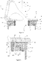
- FIG. 5 is a close-up view of the rear side of the yaw bearing of Figure 4 .
- the first bearing component 31 in this example comprises a top axial gliding surface 311, a bottom axial gliding surface 313 and a radial gliding surface 312. These gliding surfaces may engage with the corresponding gliding surfaces of the second bearing component 32.
- the second bearing component 32 in these examples also includes a top axial gliding surface 321, a bottom axial gliding surface 323 and a radial gliding surface 322.
- the top axial gliding surface 311 of the first bearing component 31 may face the top axial gliding surface 321 of the second bearing component 32.
- the bottom axial gliding surfaces and the radial gliding surfaces may respectively face to each other.
- One or more axial gliding pads 51 may be arranged between the top axial gliding surfaces 311,321 of the first and the second bearing components.
- the yaw bearing may further comprise bottom axial gliding pads 53 arranged between the bottom axial gliding surfaces 313, 323 and radial gliding pads 52 arranged between the radial gliding surfaces 312, 322. Accordingly, the friction between the gliding surfaces of the bearing components may be controlled.
- the gliding pads may include grease or lubrication in order to reduce the friction coefficient and reduce or control noise. Vibrations of the nacelle may also be absorbed by the gliding pads.
- one or more of the gliding pads may comprise a pressure system for controlling the pressure provided by the gliding pads to the gliding surfaces. The friction between the adjacent gliding surfaces may thus be controlled.
- the pressure system may comprise a spring or a bolt that adjust the pressure between the two bearing components.
- the pressure system may comprise pneumatic or hydraulic pre-tension elements.
- the axial gliding pads 51 may be fitted in the receptacles 34 of the first bearing component 31.
- the top axial gliding surface 311 comprises the receptacles 34.
- the axial gliding pads may be coupled to the first bearing component 31.
- the cut-out 35 is arranged at an outer side of the yaw bearing.
- the cut-out may communicate an outside the yaw bearing and an axial gliding pad 51.
- an axial gliding pad may be removed from the yaw bearing by substantially making this axial gliding pad coincide with the cut-out or opening.
- the cut-out 35 may extend from an outer side to an inner side of the gliding pad.
- such an axial gliding pad 51 may be removed to an outside the yaw bearing, e.g. an outside the tower and/or the nacelle through the cut-out 35.
- An axial gliding pad may be extracted outwardly through the cut-out 35.
- the cut-out may be arranged at an inner side of the yaw bearing.
- the cut-out may communicate the top gliding surface 311 of the first bearing component and an inner side of the yaw bearing.
- An axial gliding pad may thus be extracted inwardly through the cut-out.
- Such an axial gliding pad may be removed to an inside the yaw bearing, e.g. an inside the tower and/or the nacelle through the cut-out.
- the radial gliding pads 52 and the bottom axial gliding pads 53 may be coupled to the second bearing component 32.
- the radial and the bottom gliding pads are coupled to the bracket 33, e.g. glued to the bracket.
- the bracket 33 may comprise the bottom axial gliding surface 323 and the radial gliding surface 322.
- the bracket may be connected to the top axial gliding surface by e.g. bolts. Accordingly, the bracket 33 may be disconnected from the remaining part of the second bearing component, e.g. a portion of the support frame, and the radial gliding pads 52 and the bottom axial gliding pads 53 may be easily removed.
- the top 311, 321 and the bottom axial gliding surface 313, 323 of the first bearing component 31 and of the second bearing component 32 may limit the up and down movement of the nacelle produced by the wind or by the weight of the rotor and/or the generator, by limiting the movement of the second bearing component 32 with respect to the first bearing component 31.
- the bracket may limit the effect of the weight of the rotor.
- Disconnecting the bracket 33 from the remaining portion of the second bearing component may thus increase the effect of tilting due to the weight of the rotor and/or the generator on the up movement of the support frame with respect to the first bearing component in the rear portion of the nacelle, i.e. the up movement of the top axial gliding surface 321 of the second bearing component with respect to the top axial gliding surface 311 of the first bearing component.
- Figure 6 schematically illustrates a close-up view of a portion of a gliding yaw bearing according to one example.
- the gliding yaw bearing comprises a first bearing component 31 configured to be coupled to a tower 2 of a wind turbine, a second bearing component 32 configured to be coupled to a nacelle of a wind turbine and one or more axial gliding pads 51 arranged between the first and the second bearing components.
- the gliding yaw bearing comprises a cut-out 35 for accessing at least one axial gliding pad of the one or more axial gliding pads.
- the one or more axial pads 51 are coupled with the second bearing component 32, rather than with the first bearing component as in the example of Figure 5 .
- the axial gliding pads 51 are thus coupled with the movable part of the wind turbine.
- the first bearing component 31 of Figure 6 comprises the cut-out 35 for accessing at least one axial gliding pad of the one or more axial gliding pads 51.
- the cut-out 35 may be a recess arranged at the top axial gliding surface 311 of the first bearing component 31.
- the axial gliding pads 51 may be attached, e.g. gluing or adhering or bolting, to the top gliding surface 321 of the second bearing component 32.
- the cut-out 35 of Figure 6 is configured to create a gap between the first bearing component 31 and at least one axial gliding pad of the one or more axial gliding pads.
- at least one axial gliding pad 51 may not be contacted by the top gliding surface 311 of the first bearing component 31 at the region of the cut-out 35. Therefore, in this example, the axial gliding pad 51 is not clamped between the first and the second bearing component at the region of the cut-out 35. This is to say that at the region of the cut-out, the first bearing component does not exert pressure on the axial gliding pads.
- the nacelle may be rotated to a position in which an axial gliding pad to be removed may substantially match the region of the cut-out 35 of the first bearing component 31.
- the axial gliding pad to be removed may thus be made coincide with the region of the cut-out 35.
- the axial gliding pads at the cut-out region may be removed from the second bearing component 32.
- the cut-out 35 may be arranged at an outer side of the yaw bearing and may communicate an outside the yaw bearing and an axial gliding pad 51.
- An axial gliding pad may thus be removed to an outside the yaw bearing, e.g. an outside the tower and/or the nacelle through the cut-out 35.
- an axial gliding pad may be extracted outwardly through the cut-out 35.
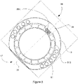
- Figure 7 schematically represents a top view of a portion of a nacelle 4 and a yaw bearing according to one example. Some components of the yaw bearing are actually not visible from this top view, for this reason axial gliding pads 51 and an cut-out 35 have been represented in dotted lines.
- the nacelle 4 extends from a front side 17 to a rear side 16 along the axis 29.
- the nacelle comprises a support frame 9 which may also extend from the front side 17 to the rear side 16 along the axis 29.
- a rotor may be coupled to the nacelle, e.g. to the support frame 9, at the front side 17.
- the support frame 9 thus supports the rotor.
- one side of a generator may be coupled to the rotor and the other side to the front side 17.
- both the rotor and the generator are thus supported by the support frame 9.
- the yaw bearing 30 comprises a first bearing component and a second bearing component (not represented in Figure 7 ) and one or more axial gliding pads arranged between them according to any of the examples herein described.
- the one or more axial gliding pads 51 are coupled with the first bearing component, i.e. are arranged at the fixed part of the bearing.
- the yaw bearing of this example comprises several axial gliding pads 51, e.g. 16 axial gliding pads, extending along at least a portion of a perimeter of the yaw bearing.
- the axial gliding pads 51 may substantially extend along the whole perimeter of yaw bearing. In some examples, the axial gliding pads may be substantially uniformly distributed along the first bearing component. In other examples, the axial gliding pads may be arranged only at regions of the first bearing component wherein higher axial loads are expected.
- the yaw bearing may comprise between 10 and 50 axial gliding pads, specifically between 15 and 40. In some examples, the yaw bearing may comprise between 20 and 30 axial gliding pads.
- the axial gliding pads may have a substantially rectangular shape.
- a length of an axial gliding pad shall be understood as the extension of the axial gliding pad along a portion of a perimeter of the yaw bearing.
- a width shall be understood as the extension along a radial direction, i.e. extending between a radially inner side to a radially outer side of the yaw bearing.
- a depth may be understood as the extension along an axial direction, i.e. extending parallel to the rotational axis of the nacelle.
- the axial gliding pads may have a length of between 250 mm (approximately 9.84 inches) to 1000 mm (approximately 39.37 inches), specifically between 500 mm (approximately 19.68 inches) to 900 mm (approximately 35.43 inches).
- the axial gliding pads may have a width of between 100 mm (approximately 3.93 inches) and 400 mm (approximately 15.75 inches), specifically between 150 mm (approximately 5.91 inches) and 300 mm (approximately 11.81 inches).
- the depth of the axial gliding pads may be between 20 mm (approximately 0.79 inches) and 200 mm (approximately 7.87 inches), specifically between 20 mm (approximately 0.79 inches) and 100 mm (approximately 3.94 inches).
- a portion of the support frame 9 comprises a cut-out 35 arranged at the rear side 16.
- This cut-out 35 may communicate an outside the yaw bearing and an axial gliding pad.
- An axial gliding pad may be removed from this cut-out.
- a tool may be inserted through the cut-out 35 and an axial gliding pad may be removed from the yaw bearing inwardly.
- a gliding axial pad may be pushed through the cut-out towards the rotational axis.
- An operator inside the tower or the nacelle may pick the removed axial gliding pad up.
- a gliding axial pad may be removed to a region inside a diameter defined by the yaw bearing.
- an axial gliding pad may be removed outwardly through the cut-out 35.
- a tool may be used for removing an axial gliding pad from inside the yaw bearing.
- An axial gliding pad may thus be extracted through the cut-out.
- a platform may be arranged for supporting an operator performing this operation. This platform may be placed inside the nacelle 4. Removing an axial gliding pad to a region outside a diameter defined by the yaw bearing may be performed inside the nacelle. Braking units and other components of the yaw system placed in an inner side of the yaw bearing may not interfere with removing an axial gliding pad.
- the cut-out 35 may have a size suitable for extracting a gliding pad or for preventing the contact between the upper gliding surface of the second bearing component and an axial gliding pad to be removed.
- the cut-out may have a length of between 300 mm (approximately 11.81 inches) and 1500 mm (approximately 55.06 inches), specifically between 800 mm (approximately 31.50 inches) and 1200 mm (approximately 47.24 inches).
- a length of the cut-out shall be understood as the extension of the cut-out substantially perpendicular to the axis 29, i.e. tangential to the yaw bearing.
- the cut-out 35 may have a length of between 200% and 90% of the length of the axial gliding pads, specifically between 150% and 100%.
- the pressure exerted by the second bearing component on the axial gliding pads is not uniform.
- the region of the second bearing component having the cut-out exerts less pressure on the axial gliding pads than in other regions of the second bearing component. Therefore, the pressure exerted by the axial sliding surface on the axial gliding pad 51B may be inferior to the pressure exerted on the gliding pad 51A.
- the second bearing component may not contact at least one axial gliding 51B arranged substantially matching with the cut-out 35.
- the weight supported by the front side 17 may tilt the nacelle forwards, in particular in direct drive wind turbines.
- the axial gliding surface of the second bearing component at the rear portion 16 may tend to move up.
- the pressure exerted by the axial gliding surface on the gliding pad 51B may thus be inferior to the pressure exerted on the gliding pad 51A.
- the pressure exerted by the second bearing component on an axial gliding pad to be removed may be released by the cut-out arranged at the top axial gliding surface of the second bearing component.
- the pressure exerted by the second bearing component on an axial gliding pad to be removed may be released by the effect of the weight of the rotor and/or of the generator. This may be in direct drive wind turbines.
- both the effect weight of the rotor and/or the generator and the cut-out may release the pressure exerted by the second bearing component on the axial gliding pad to be removed.
- the gliding pad 51A is selected to be removed. However, the orientation of the nacelle does not allow removing this axial gliding pad 51A from this position.
- Figure 8 schematically represents the top view of a portion of Figure 7 wherein the nacelle is in a removal position.
- the nacelle rotates around the rotational axis from Figure 7 to Figure 8 to a removal position.
- the axial gliding pad 51A may be removed.
- the front side 17 is positioned substantially diametrically opposite to the axial gliding pad 51A to be removed.
- the axial gliding pad to be removed 51A is substantially at or closed to the rear portion 16 of the support frame 9 or nacelle.
- the rear portion 16 may thus match the position of the axial gliding pad to be removed 51A.
- the cut-out may match the axial gliding pad to be removed 51A.
- the weight of the rotor and/or of the generators may release or help to release the force of the second bearing component against the axial gliding pad to be removed 51A.
- the axial gliding pad 51A may thus be removed.
- Removing the axial gliding pad 51A may be facilitated by the cut-out 35.
- the cut-out may increase the distance between the top axial surfaces of the first and the second components. In the removal position, the cut-out may substantially match the axial gliding pad 51A.
- rotating the nacelle for removing an axial gliding pad may also be used in those wind turbines wherein the weight of the rotor and/or of the generator is not capable of moving away in a sufficient manner the second bearing component with respect the first bearing component. This may be the case in wind turbines having a gearbox arranged inside the nacelle.
- the nacelle may be rotated as previously described. However, in these examples, the nacelles may rotate in order to make an axial gliding pad to be removed coincide with the region of the cut-out of the first bearing component.
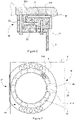
- Figure 9 schematically illustrates a first bearing component according to one example.
- the first bearing component 31 of figure 9 comprises one or more receptacles 34.
- the top axial gliding surface 311 comprises these receptacles 34.
- the first bearing component comprises an annular gear 21.
- the annular gear 21 and the first bearing component 31 may be integrally formed in a single piece.
- the first bearing component may be manufactured by casting.
- the receptacles 34 may extend along at least a portion of a perimeter of the first bearing component 31. In some examples, the receptacles 34 may substantially extend along the whole perimeter of the first bearing component 31.
- the receptacles may be substantially uniformly distributed along the first bearing component. In other examples, the receptacles may be arranged only at regions of the first bearing component wherein higher axial loads are expected.
- one axial gliding pad may be arranged in one receptacle 34.
- length and width of the receptacles may be similar to the length and width of the axial gliding pads.
- length and width of the receptacles may be according to any of the examples of axial gliding pads herein disclosed.
- several axial gliding pads may be arranged at a single receptacle.
- size of the receptacles may be suitable for engaging the axial gliding pads.
- a depth of the receptacles may be higher than the depth of the axial gliding pads.
- the axial gliding pad may thus be clamped between the gliding upper surface 311 of first bearing component and the gliding upper surface of the second bearing component.
- the receptacles 34 are separated by bridges 344. These bridges 344 may connect the radial gliding surface 312 and the annular gear 21.
- the receptacles 34 may comprise an outer radial sidewall 341. Outwardly movements of the axial gliding pads may thus be prevented.
- the receptacles 34 may comprise an inner radial sidewall 342. Inwardly movements of the axial gliding pads may thus be prevented. In the examples of receptacles having an inner radial sidewall 342 and an outer radial sidewall 341, coupling between the axial gliding pad and the first bearing component 31 may thus be enhanced.
- the inner radial sidewall 342 comprises a notch 343.
- the notch 343 may have a shape suitable for inserting a lever tool.
- a lever tool e.g. screwdriver, may thus be inserted in the notch 343 to disengage the axial gliding pad from the receptacle 34.
- a wind turbine comprising a tower and a nacelle mounted on the tower and extending between a front side to a rear side.
- the wind turbine further comprises a rotor including a rotor hub and at least one rotor blade, the rotor being arranged at the front side.
- the wind turbine comprises a gliding yaw bearing for rotating the nacelle with respect to the tower.
- the gliding yaw bearing may be according to any of the examples herein disclosed.
- the gliding yaw bearing may comprise a cut-out for accessing one gliding pad.
- the cut-out may be arranged substantially diametrically opposite to the front side of the nacelle.
- the second bearing component e.g. a portion of the support frame
- the cut-out may be arranged at the rear side of the nacelle, e.g. at the rear portion of the support frame.
- the gliding yaw bearing may comprise a first bearing component coupled to the tower and a second bearing component coupled to the nacelle.
- the first bearing component may be configured to rotate with respect to the second bearing component.
- the gliding yaw bearing may comprise one or more axial gliding pads arranged between the first and the second bearing components.
- the axial gliding pads may be coupled with the first bearing component.
- the first bearing component may comprise one or more receptacles. Each of the receptacles may be configured to receive at least one of the axial gliding pads.
- the axial gliding pads may be arranged between the top axial gliding surface 311, 321 of the first and second bearing components.
- the axial gliding pads may thus be connected to the first bearing component.
- Each of the receptacles may engage with at least one of the axial gliding pads.
- the nacelle may comprise a support frame.
- the second bearing component may comprise a portion of the support frame.
- the axial gliding pads may be coupled with the second bearing component 32.
- the yaw bearing may comprise a cut-out 35 arranged at the first bearing component 31.
- the wind turbine may be directly driven, i.e. the wind turbine may be a direct drive wind turbine.
- the wind turbine may be driven by a gearbox coupled with the rotor through a shaft.
- the gearbox may be arranged inside the nacelle, e.g. supported by the support frame.
- Figure 10 is a flow diagram of a method for removing gliding pad of a gliding yaw bearing of a wind turbine.
- the method 100 for removing an axial gliding pad of a gliding yaw bearing comprises selecting 101 a gliding pad to be removed.
- rotating a nacelle that is rotatably mounted on a tower through the gliding yaw bearing to a removal position is represented.
- the front side is positioned substantially diametrically opposite to the selected gliding pad, such that the pressure exerted on the selected pad is released.
- the selected gliding pad to be removed is substantially positioned at the rear side of the nacelle.
- the rear side of the nacelle is substantially positioned close or at the region of the selected gliding pad.
- Block 103 represents removing the selected gliding pad. When the pressure exerted on the gliding pad to be removed is sufficiently low, this gliding pad may be removed.
- the wind turbine may comprise a tower, a rotor including a rotor hub and at least one rotor blade and a nacelle mounted on the tower and extending from a front side to a rear side.
- the rotor may be arranged at the front side of the nacelle.
- the gliding yaw bearing may comprise a first bearing component coupled to the tower and a second bearing component coupled to the nacelle.
- the first bearing component is configured to rotate with respect to the second bearing component.
- the gliding yaw bearing comprises one or more axial gliding pads arranged between the first and the second bearing components, in such a way that the first and the second bearing components exert a pressure on the gliding pads.
- a gap may be created between the selected guiding pad and one of the first and second bearing components.
- the method may comprise removing the selected gliding pad in a direction moving away from the front side.
- the method may comprise removing the selected gliding pad in a direction towards the front side.
- the pressure may be released by the action of the weight of the rotor and/or of the generator.
- the method may further comprise tilting the nacelle at the removal position by the action of the weight of a rotor and/or a generator of the wind turbine.
- the generator may be arranged between the rotor and the nacelle.
- the weight of the rotor and/or the generator is displaced from the rotational axis of the nacelle. This weight may tilt the nacelle towards the front side. This tilt towards the rotor region may allow a portion of the nacelle in a region opposite to the front side, i.e. in a rear side, to be moved away from the tower. Consequently, as the first and the second bearing components are respectively coupled to the tower and to the nacelle, the second bearing component may be moved away from the first bearing component in the region opposite to front side, i.e. opposite to the rotor. This relative displacement may release the pressure exerted by the second bearing component on the axial gliding pad and a gap between the bearing components sufficient for removing the selected axial gliding pad may be created.
- This method may get benefit from having the center of gravity of the direct drive wind turbine in a position forward from the rotational axis of the wind turbine, i.e. the center of gravity is displaced towards the rotor region of the wind turbine. Therefore, existing components of wind turbines, e.g. the rotor and the generator, may be used to go up a portion of the second bearing component with respect to the first bearing component when the nacelle is positioned in a removal position.
- the second bearing component may comprise a bracket according to any of the examples herein described.
- the bracket may be connected to a portion of the second bearing component, e.g. to a portion of the support frame, and the bracket may partially enclose the first bearing component.
- the method may further comprise disconnecting the bracket form the portion of the second bearing component.
- up and down movements of the second bearing components with respect to the first bearing component may be prevented.
- the tilting effect generated by the weight of the rotor and/or of the generator may thus be enhanced by disconnecting the bracket from the portion of the second bearing component, e.g. a portion of the support frame.
- the pressure on the axial gliding pad to be removed may be released by providing a cut-out at the gliding yaw bearing, e.g. at the second bearing component.
- the second bearing component may thus comprise a cut-out arranged substantially at the opposite region of the front side.
- the first bearing component may comprise receptacles according to any of the examples herein disclosed.
- a lever tool may be used for disengaging the axial gliding pad to be removed from the receptacle.
- a notch may be provided in the receptacles for inserting the lever tool. The selected axial gliding pad may be easily removed.
Landscapes
- Engineering & Computer Science (AREA)
- General Engineering & Computer Science (AREA)
- Mechanical Engineering (AREA)
- Life Sciences & Earth Sciences (AREA)
- Sustainable Development (AREA)
- Sustainable Energy (AREA)
- Chemical & Material Sciences (AREA)
- Combustion & Propulsion (AREA)
- Wind Motors (AREA)
Priority Applications (5)
| Application Number | Priority Date | Filing Date | Title |
|---|---|---|---|
| EP18382867.2A EP3660302B1 (en) | 2018-11-29 | 2018-11-29 | Yaw system for a wind turbine |
| PL18382867.2T PL3660302T3 (pl) | 2018-11-29 | 2018-11-29 | System odchylania dla turbiny wiatrowej |
| ES18382867T ES2941796T3 (es) | 2018-11-29 | 2018-11-29 | Sistema de orientación para una turbina eólica |
| US16/693,824 US11280320B2 (en) | 2018-11-29 | 2019-11-25 | Yaw system for a wind turbine |
| CN201911200143.6A CN111237125B (zh) | 2018-11-29 | 2019-11-29 | 用于风力涡轮的偏航系统 |
Applications Claiming Priority (1)
| Application Number | Priority Date | Filing Date | Title |
|---|---|---|---|
| EP18382867.2A EP3660302B1 (en) | 2018-11-29 | 2018-11-29 | Yaw system for a wind turbine |
Publications (2)
| Publication Number | Publication Date |
|---|---|
| EP3660302A1 EP3660302A1 (en) | 2020-06-03 |
| EP3660302B1 true EP3660302B1 (en) | 2023-01-04 |
Family
ID=64665085
Family Applications (1)
| Application Number | Title | Priority Date | Filing Date |
|---|---|---|---|
| EP18382867.2A Active EP3660302B1 (en) | 2018-11-29 | 2018-11-29 | Yaw system for a wind turbine |
Country Status (5)
| Country | Link |
|---|---|
| US (1) | US11280320B2 (pl) |
| EP (1) | EP3660302B1 (pl) |
| CN (1) | CN111237125B (pl) |
| ES (1) | ES2941796T3 (pl) |
| PL (1) | PL3660302T3 (pl) |
Families Citing this family (11)
| Publication number | Priority date | Publication date | Assignee | Title |
|---|---|---|---|---|
| AT521884B1 (de) * | 2018-12-13 | 2020-10-15 | Miba Gleitlager Austria Gmbh | Verfahren zum Wechseln eines Gleitlagerelementes einer Rotorlagerung einer Windkraftanlage, sowie Gondel für eine Windkraftanlage |
| AT521775B1 (de) | 2018-12-13 | 2020-06-15 | Miba Gleitlager Austria Gmbh | Planetengetriebe für eine Windkraftanlage |
| AT521885B1 (de) | 2018-12-13 | 2020-09-15 | Miba Gleitlager Austria Gmbh | Gondel für eine Windkraftanlage |
| AT521953B1 (de) | 2018-12-13 | 2020-07-15 | Miba Gleitlager Austria Gmbh | Gondel für eine Windkraftanlage |
| AT521687B1 (de) | 2018-12-13 | 2020-04-15 | Miba Gleitlager Austria Gmbh | Gondel für eine Windkraftanlage |
| PL3922850T3 (pl) * | 2020-06-11 | 2023-12-04 | General Electric Renovables España S.L. | Łożyska odchylania do turbiny wiatrowej |
| USD1042341S1 (en) | 2021-12-21 | 2024-09-17 | Kodair Wind Designs Limited | Wind turbine |
| EP4343149A1 (en) * | 2022-09-21 | 2024-03-27 | Siemens Gamesa Renewable Energy A/S | Fluid film bearing comprising bearing pads and method of replacing bearing pads |
| EP4343148A1 (en) * | 2022-09-21 | 2024-03-27 | Siemens Gamesa Renewable Energy A/S | Fluid film bearing comprising bearing pads and method of replacing bearing pads |
| CN116538030B (zh) * | 2023-05-30 | 2026-03-06 | 西安热工研究院有限公司 | 一种风电主机架及其制造工艺 |
| US20250243841A1 (en) * | 2024-01-31 | 2025-07-31 | Kodair Wind Designs Limited | Yaw drive system |
Family Cites Families (12)
| Publication number | Priority date | Publication date | Assignee | Title |
|---|---|---|---|---|
| US20060292349A1 (en) | 2005-05-05 | 2006-12-28 | Seeley Frederic F | An evaporative material system and method of manufacture |
| ES2326852B1 (es) * | 2006-12-26 | 2010-07-15 | GAMESA INNOVATION & TECHNOLOGY, S.L. | Corona de guiñada con base deslizante en aerogeneradores. |
| CN201326521Y (zh) * | 2008-12-24 | 2009-10-14 | 华锐风电科技有限公司 | 风力发电机组滑动式偏航轴承装置 |
| AT509625B1 (de) * | 2010-04-14 | 2012-02-15 | Miba Gleitlager Gmbh | Lagerelement |
| EP2388480B1 (en) | 2010-08-31 | 2013-10-30 | Mitsubishi Heavy Industries, Ltd. | Maintenance method for wind power generation device |
| EP2679815B1 (en) * | 2012-06-26 | 2017-02-01 | ALSTOM Renewable Technologies | Wind turbine with a rotating assembly |
| EP2711568B1 (en) * | 2012-09-24 | 2018-05-30 | Siemens Aktiengesellschaft | Sliding bearing and method to perform service at the sliding bearing |
| DK2837818T3 (en) * | 2013-08-13 | 2019-03-11 | Siemens Ag | Wind turbine with bend bearing lift device |
| DK3165764T3 (da) * | 2015-11-06 | 2021-06-21 | Sb Patent Holding Aps | Yaw-bremse til en vindturbine |
| CN207647700U (zh) * | 2017-12-26 | 2018-07-24 | 新疆金风科技股份有限公司 | 偏航对风结构和风力发电机组 |
| CN108105042B (zh) * | 2018-01-19 | 2019-07-12 | 国华爱依斯(黄骅)风电有限公司 | 一种风力发电机组中偏航衬垫的更换方法 |
| US11319935B2 (en) * | 2018-04-16 | 2022-05-03 | Siemens Gamesa Renewable Energy A/S | Method for replacing a wind turbine pad |
-
2018
- 2018-11-29 ES ES18382867T patent/ES2941796T3/es active Active
- 2018-11-29 EP EP18382867.2A patent/EP3660302B1/en active Active
- 2018-11-29 PL PL18382867.2T patent/PL3660302T3/pl unknown
-
2019
- 2019-11-25 US US16/693,824 patent/US11280320B2/en active Active
- 2019-11-29 CN CN201911200143.6A patent/CN111237125B/zh active Active
Also Published As
| Publication number | Publication date |
|---|---|
| EP3660302A1 (en) | 2020-06-03 |
| CN111237125A (zh) | 2020-06-05 |
| CN111237125B (zh) | 2024-10-29 |
| PL3660302T3 (pl) | 2023-03-27 |
| US11280320B2 (en) | 2022-03-22 |
| US20200173424A1 (en) | 2020-06-04 |
| ES2941796T3 (es) | 2023-05-25 |
Similar Documents
| Publication | Publication Date | Title |
|---|---|---|
| EP3660302B1 (en) | Yaw system for a wind turbine | |
| US12338798B2 (en) | Uptower main bearing replacement | |
| EP2317137B1 (en) | Configuration of a wind turbine nacelle | |
| EP3597903B1 (en) | Yaw system for a wind turbine | |
| EP2759701B1 (en) | Power generating apparatus of renewable energy type | |
| KR20110114428A (ko) | 풍력 발전 장치용의 로터 터닝 장치 및 로터 터닝 방법 | |
| EP3431752A1 (en) | Method for removing or installing rotor blade hardware of a wind turbine | |
| CN108661864A (zh) | 用于风轮机的齿轮箱组件的修理方法 | |
| EP3730783B1 (en) | System and method for repairing a gearbox of a wind turbine uptower | |
| EP4102065A1 (en) | Hub-shaft bolted-joint connection of a wind turbine | |
| US20210108620A1 (en) | System and Method for Locking of a Rotor of a Wind Turbine during Extended Maintenance | |
| EP3450749B1 (en) | Hoistable induction and cooling unit for wind turbine maintenance | |
| EP2530300B1 (en) | Nacelle main frame structure and drive train assembly for a wind turbine | |
| EP3382200A1 (en) | Hub crane assembly for a wind turbine | |
| EP2607684B1 (en) | Means to rotate the rotor of a wind turbine and method to rotate the rotor | |
| US12497946B2 (en) | Service brake for a wind turbine yaw motor | |
| KR101444363B1 (ko) | 풍력발전 설비의 유지보수 장치 | |
| EP3364023B1 (en) | System and method for removing or installing a main shaft of a wind turbine | |
| CN121701426A (zh) | 更换轴承的方法以及风力发电机 | |
| CN113896086A (zh) | 一种用于风电齿轮箱端盖拆卸的吊具及方法 |
Legal Events
| Date | Code | Title | Description |
|---|---|---|---|
| PUAI | Public reference made under article 153(3) epc to a published international application that has entered the european phase |
Free format text: ORIGINAL CODE: 0009012 |
|
| STAA | Information on the status of an ep patent application or granted ep patent |
Free format text: STATUS: THE APPLICATION HAS BEEN PUBLISHED |
|
| AK | Designated contracting states |
Kind code of ref document: A1 Designated state(s): AL AT BE BG CH CY CZ DE DK EE ES FI FR GB GR HR HU IE IS IT LI LT LU LV MC MK MT NL NO PL PT RO RS SE SI SK SM TR |
|
| AX | Request for extension of the european patent |
Extension state: BA ME |
|
| STAA | Information on the status of an ep patent application or granted ep patent |
Free format text: STATUS: REQUEST FOR EXAMINATION WAS MADE |
|
| 17P | Request for examination filed |
Effective date: 20201203 |
|
| RBV | Designated contracting states (corrected) |
Designated state(s): AL AT BE BG CH CY CZ DE DK EE ES FI FR GB GR HR HU IE IS IT LI LT LU LV MC MK MT NL NO PL PT RO RS SE SI SK SM TR |
|
| STAA | Information on the status of an ep patent application or granted ep patent |
Free format text: STATUS: EXAMINATION IS IN PROGRESS |
|
| 17Q | First examination report despatched |
Effective date: 20220328 |
|
| GRAP | Despatch of communication of intention to grant a patent |
Free format text: ORIGINAL CODE: EPIDOSNIGR1 |
|
| STAA | Information on the status of an ep patent application or granted ep patent |
Free format text: STATUS: GRANT OF PATENT IS INTENDED |
|
| INTG | Intention to grant announced |
Effective date: 20221013 |
|
| GRAS | Grant fee paid |
Free format text: ORIGINAL CODE: EPIDOSNIGR3 |
|
| GRAA | (expected) grant |
Free format text: ORIGINAL CODE: 0009210 |
|
| STAA | Information on the status of an ep patent application or granted ep patent |
Free format text: STATUS: THE PATENT HAS BEEN GRANTED |
|
| AK | Designated contracting states |
Kind code of ref document: B1 Designated state(s): AL AT BE BG CH CY CZ DE DK EE ES FI FR GB GR HR HU IE IS IT LI LT LU LV MC MK MT NL NO PL PT RO RS SE SI SK SM TR |
|
| REG | Reference to a national code |
Ref country code: GB Ref legal event code: FG4D |
|
| REG | Reference to a national code |
Ref country code: CH Ref legal event code: EP |
|
| REG | Reference to a national code |
Ref country code: AT Ref legal event code: REF Ref document number: 1542103 Country of ref document: AT Kind code of ref document: T Effective date: 20230115 |
|
| REG | Reference to a national code |
Ref country code: DE Ref legal event code: R096 Ref document number: 602018044977 Country of ref document: DE |
|
| REG | Reference to a national code |
Ref country code: IE Ref legal event code: FG4D |
|
| REG | Reference to a national code |
Ref country code: NL Ref legal event code: FP |
|
| REG | Reference to a national code |
Ref country code: LT Ref legal event code: MG9D |
|
| REG | Reference to a national code |
Ref country code: ES Ref legal event code: FG2A Ref document number: 2941796 Country of ref document: ES Kind code of ref document: T3 Effective date: 20230525 |
|
| REG | Reference to a national code |
Ref country code: AT Ref legal event code: MK05 Ref document number: 1542103 Country of ref document: AT Kind code of ref document: T Effective date: 20230104 |
|
| P01 | Opt-out of the competence of the unified patent court (upc) registered |
Effective date: 20230529 |
|
| PG25 | Lapsed in a contracting state [announced via postgrant information from national office to epo] |
Ref country code: RS Free format text: LAPSE BECAUSE OF FAILURE TO SUBMIT A TRANSLATION OF THE DESCRIPTION OR TO PAY THE FEE WITHIN THE PRESCRIBED TIME-LIMIT Effective date: 20230104 Ref country code: PT Free format text: LAPSE BECAUSE OF FAILURE TO SUBMIT A TRANSLATION OF THE DESCRIPTION OR TO PAY THE FEE WITHIN THE PRESCRIBED TIME-LIMIT Effective date: 20230504 Ref country code: NO Free format text: LAPSE BECAUSE OF FAILURE TO SUBMIT A TRANSLATION OF THE DESCRIPTION OR TO PAY THE FEE WITHIN THE PRESCRIBED TIME-LIMIT Effective date: 20230404 Ref country code: LV Free format text: LAPSE BECAUSE OF FAILURE TO SUBMIT A TRANSLATION OF THE DESCRIPTION OR TO PAY THE FEE WITHIN THE PRESCRIBED TIME-LIMIT Effective date: 20230104 Ref country code: LT Free format text: LAPSE BECAUSE OF FAILURE TO SUBMIT A TRANSLATION OF THE DESCRIPTION OR TO PAY THE FEE WITHIN THE PRESCRIBED TIME-LIMIT Effective date: 20230104 Ref country code: HR Free format text: LAPSE BECAUSE OF FAILURE TO SUBMIT A TRANSLATION OF THE DESCRIPTION OR TO PAY THE FEE WITHIN THE PRESCRIBED TIME-LIMIT Effective date: 20230104 Ref country code: AT Free format text: LAPSE BECAUSE OF FAILURE TO SUBMIT A TRANSLATION OF THE DESCRIPTION OR TO PAY THE FEE WITHIN THE PRESCRIBED TIME-LIMIT Effective date: 20230104 |
|
| PG25 | Lapsed in a contracting state [announced via postgrant information from national office to epo] |
Ref country code: SE Free format text: LAPSE BECAUSE OF FAILURE TO SUBMIT A TRANSLATION OF THE DESCRIPTION OR TO PAY THE FEE WITHIN THE PRESCRIBED TIME-LIMIT Effective date: 20230104 Ref country code: IS Free format text: LAPSE BECAUSE OF FAILURE TO SUBMIT A TRANSLATION OF THE DESCRIPTION OR TO PAY THE FEE WITHIN THE PRESCRIBED TIME-LIMIT Effective date: 20230504 Ref country code: GR Free format text: LAPSE BECAUSE OF FAILURE TO SUBMIT A TRANSLATION OF THE DESCRIPTION OR TO PAY THE FEE WITHIN THE PRESCRIBED TIME-LIMIT Effective date: 20230405 Ref country code: FI Free format text: LAPSE BECAUSE OF FAILURE TO SUBMIT A TRANSLATION OF THE DESCRIPTION OR TO PAY THE FEE WITHIN THE PRESCRIBED TIME-LIMIT Effective date: 20230104 |
|
| REG | Reference to a national code |
Ref country code: DE Ref legal event code: R097 Ref document number: 602018044977 Country of ref document: DE |
|
| PG25 | Lapsed in a contracting state [announced via postgrant information from national office to epo] |
Ref country code: SM Free format text: LAPSE BECAUSE OF FAILURE TO SUBMIT A TRANSLATION OF THE DESCRIPTION OR TO PAY THE FEE WITHIN THE PRESCRIBED TIME-LIMIT Effective date: 20230104 Ref country code: RO Free format text: LAPSE BECAUSE OF FAILURE TO SUBMIT A TRANSLATION OF THE DESCRIPTION OR TO PAY THE FEE WITHIN THE PRESCRIBED TIME-LIMIT Effective date: 20230104 Ref country code: EE Free format text: LAPSE BECAUSE OF FAILURE TO SUBMIT A TRANSLATION OF THE DESCRIPTION OR TO PAY THE FEE WITHIN THE PRESCRIBED TIME-LIMIT Effective date: 20230104 Ref country code: DK Free format text: LAPSE BECAUSE OF FAILURE TO SUBMIT A TRANSLATION OF THE DESCRIPTION OR TO PAY THE FEE WITHIN THE PRESCRIBED TIME-LIMIT Effective date: 20230104 Ref country code: CZ Free format text: LAPSE BECAUSE OF FAILURE TO SUBMIT A TRANSLATION OF THE DESCRIPTION OR TO PAY THE FEE WITHIN THE PRESCRIBED TIME-LIMIT Effective date: 20230104 |
|
| PLBE | No opposition filed within time limit |
Free format text: ORIGINAL CODE: 0009261 |
|
| STAA | Information on the status of an ep patent application or granted ep patent |
Free format text: STATUS: NO OPPOSITION FILED WITHIN TIME LIMIT |
|
| PG25 | Lapsed in a contracting state [announced via postgrant information from national office to epo] |
Ref country code: SK Free format text: LAPSE BECAUSE OF FAILURE TO SUBMIT A TRANSLATION OF THE DESCRIPTION OR TO PAY THE FEE WITHIN THE PRESCRIBED TIME-LIMIT Effective date: 20230104 |
|
| 26N | No opposition filed |
Effective date: 20231005 |
|
| PG25 | Lapsed in a contracting state [announced via postgrant information from national office to epo] |
Ref country code: SI Free format text: LAPSE BECAUSE OF FAILURE TO SUBMIT A TRANSLATION OF THE DESCRIPTION OR TO PAY THE FEE WITHIN THE PRESCRIBED TIME-LIMIT Effective date: 20230104 |
|
| PG25 | Lapsed in a contracting state [announced via postgrant information from national office to epo] |
Ref country code: IT Free format text: LAPSE BECAUSE OF FAILURE TO SUBMIT A TRANSLATION OF THE DESCRIPTION OR TO PAY THE FEE WITHIN THE PRESCRIBED TIME-LIMIT Effective date: 20230104 |
|
| REG | Reference to a national code |
Ref country code: CH Ref legal event code: PL |
|
| PG25 | Lapsed in a contracting state [announced via postgrant information from national office to epo] |
Ref country code: MC Free format text: LAPSE BECAUSE OF FAILURE TO SUBMIT A TRANSLATION OF THE DESCRIPTION OR TO PAY THE FEE WITHIN THE PRESCRIBED TIME-LIMIT Effective date: 20230104 |
|
| PG25 | Lapsed in a contracting state [announced via postgrant information from national office to epo] |
Ref country code: LU Free format text: LAPSE BECAUSE OF NON-PAYMENT OF DUE FEES Effective date: 20231129 |
|
| PG25 | Lapsed in a contracting state [announced via postgrant information from national office to epo] |
Ref country code: CH Free format text: LAPSE BECAUSE OF NON-PAYMENT OF DUE FEES Effective date: 20231130 |
|
| PG25 | Lapsed in a contracting state [announced via postgrant information from national office to epo] |
Ref country code: MC Free format text: LAPSE BECAUSE OF FAILURE TO SUBMIT A TRANSLATION OF THE DESCRIPTION OR TO PAY THE FEE WITHIN THE PRESCRIBED TIME-LIMIT Effective date: 20230104 Ref country code: LU Free format text: LAPSE BECAUSE OF NON-PAYMENT OF DUE FEES Effective date: 20231129 Ref country code: CH Free format text: LAPSE BECAUSE OF NON-PAYMENT OF DUE FEES Effective date: 20231130 |
|
| REG | Reference to a national code |
Ref country code: BE Ref legal event code: MM Effective date: 20231130 |
|
| PG25 | Lapsed in a contracting state [announced via postgrant information from national office to epo] |
Ref country code: BE Free format text: LAPSE BECAUSE OF NON-PAYMENT OF DUE FEES Effective date: 20231130 |
|
| PG25 | Lapsed in a contracting state [announced via postgrant information from national office to epo] |
Ref country code: BE Free format text: LAPSE BECAUSE OF NON-PAYMENT OF DUE FEES Effective date: 20231130 |
|
| PG25 | Lapsed in a contracting state [announced via postgrant information from national office to epo] |
Ref country code: BG Free format text: LAPSE BECAUSE OF FAILURE TO SUBMIT A TRANSLATION OF THE DESCRIPTION OR TO PAY THE FEE WITHIN THE PRESCRIBED TIME-LIMIT Effective date: 20230104 |
|
| PG25 | Lapsed in a contracting state [announced via postgrant information from national office to epo] |
Ref country code: BG Free format text: LAPSE BECAUSE OF FAILURE TO SUBMIT A TRANSLATION OF THE DESCRIPTION OR TO PAY THE FEE WITHIN THE PRESCRIBED TIME-LIMIT Effective date: 20230104 |
|
| PG25 | Lapsed in a contracting state [announced via postgrant information from national office to epo] |
Ref country code: CY Free format text: LAPSE BECAUSE OF FAILURE TO SUBMIT A TRANSLATION OF THE DESCRIPTION OR TO PAY THE FEE WITHIN THE PRESCRIBED TIME-LIMIT; INVALID AB INITIO Effective date: 20181129 |
|
| PG25 | Lapsed in a contracting state [announced via postgrant information from national office to epo] |
Ref country code: HU Free format text: LAPSE BECAUSE OF FAILURE TO SUBMIT A TRANSLATION OF THE DESCRIPTION OR TO PAY THE FEE WITHIN THE PRESCRIBED TIME-LIMIT; INVALID AB INITIO Effective date: 20181129 |
|
| PGFP | Annual fee paid to national office [announced via postgrant information from national office to epo] |
Ref country code: NL Payment date: 20251022 Year of fee payment: 8 |
|
| PG25 | Lapsed in a contracting state [announced via postgrant information from national office to epo] |
Ref country code: TR Free format text: LAPSE BECAUSE OF FAILURE TO SUBMIT A TRANSLATION OF THE DESCRIPTION OR TO PAY THE FEE WITHIN THE PRESCRIBED TIME-LIMIT Effective date: 20230104 |
|
| PGFP | Annual fee paid to national office [announced via postgrant information from national office to epo] |
Ref country code: DE Payment date: 20251022 Year of fee payment: 8 |
|
| PGFP | Annual fee paid to national office [announced via postgrant information from national office to epo] |
Ref country code: GB Payment date: 20251023 Year of fee payment: 8 |
|
| PGFP | Annual fee paid to national office [announced via postgrant information from national office to epo] |
Ref country code: FR Payment date: 20251022 Year of fee payment: 8 |
|
| PGFP | Annual fee paid to national office [announced via postgrant information from national office to epo] |
Ref country code: IE Payment date: 20251024 Year of fee payment: 8 |
|
| PGFP | Annual fee paid to national office [announced via postgrant information from national office to epo] |
Ref country code: PL Payment date: 20251023 Year of fee payment: 8 |
|
| PGFP | Annual fee paid to national office [announced via postgrant information from national office to epo] |
Ref country code: ES Payment date: 20251201 Year of fee payment: 8 |