EP3659867A1 - Method for manufacturing a retro-reflecting vehicle number plate, retro-reflecting vehicle number plate, and device for implementing the method - Google Patents
Method for manufacturing a retro-reflecting vehicle number plate, retro-reflecting vehicle number plate, and device for implementing the method Download PDFInfo
- Publication number
- EP3659867A1 EP3659867A1 EP19219268.0A EP19219268A EP3659867A1 EP 3659867 A1 EP3659867 A1 EP 3659867A1 EP 19219268 A EP19219268 A EP 19219268A EP 3659867 A1 EP3659867 A1 EP 3659867A1
- Authority
- EP
- European Patent Office
- Prior art keywords
- blank
- license plate
- shield
- vehicle license
- motor vehicle
- Prior art date
- Legal status (The legal status is an assumption and is not a legal conclusion. Google has not performed a legal analysis and makes no representation as to the accuracy of the status listed.)
- Withdrawn
Links
Images


Classifications
-
- B—PERFORMING OPERATIONS; TRANSPORTING
- B60—VEHICLES IN GENERAL
- B60R—VEHICLES, VEHICLE FITTINGS, OR VEHICLE PARTS, NOT OTHERWISE PROVIDED FOR
- B60R13/00—Elements for body-finishing, identifying, or decorating; Arrangements or adaptations for advertising purposes
- B60R13/10—Registration, licensing, or like devices
Definitions
- the present invention relates to a method for producing a retroreflective motor vehicle license plate, a retroreflective motor vehicle license plate that can be produced according to the method and a device for carrying out the method.
- the invention relates to a production method for a motor vehicle license plate with novel security features, a device suitable for carrying out this method for producing a motor vehicle license plate with novel security features, and a motor vehicle license plate with novel security features.
- An Ensure TM security feature is an optical marking of the film that is only visible when the film is oriented vertically at a viewing angle of approximately 30 ° to the horizontal. Otherwise the film appears uniformly retroreflective, ie the security feature is invisible.
- a method for producing the Ensure TM Image security feature is described, for example, in US 4,691,993 A or in the EP 0 203 752 B1 described.
- the Ensure TM Image security feature is realized by targeted local damage to the metallic reflection layer contained in the retroreflective film by means of laser radiation. It therefore presupposes the existence of a dedicated metallic reflective layer in the retroreflective sheeting ahead and therefore cannot be inserted into retroreflective foils based on embedded microprisms.
- a retroreflective sheeting is marketed under the name Ensure TM Virtual Security Thread, which includes an optically perceptible security feature that is incorporated into the material of the sheeting and appears three-dimensional. It includes two virtual images, one of which appears to float above the plane of the shield and one below. When viewed directly from the film, it is also visible from a greater distance and can also be combined with the Ensure TM Image security feature. Further information on retroreflective foils with the Ensure TM Virtual Security Thread security feature can also be found in the EP 1 602 946 B1 . The Ensure TM Virtual Security Thread security feature can also only be incorporated into retroreflective foils with embedded microlenses and a metallic reflective layer.
- the Ensure TM Virtual Security Thread security feature can only be introduced during film production.
- a change in the security feature, e.g. its contour is therefore reserved for the film manufacturer, which makes the procurement of smaller quantities of film with a security feature individualized on customer request problematic and in particular cost-intensive.
- optical hologram seals as a security feature is known, which are produced in a separate manufacturing process on a separate carrier film.
- the Leonhard Kurz Foundation & Co.KG offers so-called hologram sealing foils, which comprise a polyester carrier, on which a lacquer package consisting of an adhesive layer, a structured metallization to form the optical hologram seal, a replication layer and a protective lacquer is removably arranged.
- these hologram seals are transferred from the polyester film to the surface of the license plate using a thermal transfer process and thermally welded to the surface thereof.
- Optical hologram seals of this type can be easily verified optically and are in particular also on retroreflective foils without metallic ones Reflective layer can be attached, for example on retroreflective foils based on microprismatic elements.
- attaching them to the license plate is technically complex and therefore increases the production costs of the license plate.
- the polyester carrier of the seal adheres in some areas to the surface of the license plate after the seal has been transferred to the surface of the license plate, so that a device is required which detaches the polyester carrier from the license plate again. There is also the risk of mechanical damage to the surface of the license plate.
- hologram seals are naturally non-transparent because of the metal layer contained therein, which in particular in the case of retroreflective license plate signs leads to local areas with a lack of retroreflectivity, which can be undesirable or even inadmissible according to local approval regulations.
- production of holograms customized according to customer requirements is expensive, since a master for hologram production is required for each individual motif, which is complex to produce. The creation of small series is therefore generally forbidden for reasons of cost.
- the object of the present invention is therefore to provide an inexpensive method for producing a license plate with an integrated security feature, which is inexpensive and avoids the aforementioned disadvantages. Furthermore, it is an object of the present invention to provide an advantageous license plate with an integrated security feature and one for Execution of the method according to the invention to specify a suitable device, which is therefore also suitable for producing a license plate according to the invention.
- This object is achieved by a manufacturing method for a license plate according to claim 1, a license plate according to claim 2 and a manufacturing device according to claim 13.
- the method according to the invention can often be integrated in the form of a few additional method steps directly into existing method sequences for the production of motor vehicle license plates, without requiring changes to these method sequences.
- the vehicle license plates produced by the method have a novel, optically perceptible security feature, which is based on an optically perceptible, extensively extended security structure, which is incorporated into the front surface of the blank plate and on regular, raised or recessed structures in the surface of the blank plate is based.
- These license plates therefore offer a high level of protection against counterfeiting, since the security structure forming the security feature is integrally connected to the material of the license plate blank, in particular here to the label plate or to a plastic film laminated thereon.
- a method according to the invention is provided for the production of a license plate.
- it comprises the step of providing a blank shield, e.g. a shield plate made of plastic or a metallic shield plate with laminated colored plastic film.
- a blank plate can already be a ready-to-use vehicle license plate, which is only provided with the security structure according to the invention within the scope of the method according to the invention.
- an optically perceptible, in particular extensive security structure is now introduced into the front surface of the shield blank in a suitable manner.
- This should include processes that either locally deform the material of the shield blank on its front surface or remove it locally.
- This formulation should not explicitly include processes in which additional material is applied to the front surface of the shield blank.
- This security structure introduced according to the invention comprises extensive, regular, raised or recessed structures in the surface of the shield blank, which are designed in such a way that the security structure introduced has an optical effect based on optical interference, in particular a color effect.
- the regular distances between the structures introduced are therefore advantageously of the order of magnitude of the wavelength of visible light, in particular in the range between 150 nanometers and 30 micrometers, particularly preferably between 450 and 1500 nanometers.
- the dominant structure size of the introduced microstructure can be tailored to customer needs within the above-mentioned framework.
- microstructures can be created that are under certain Reflect angles through constructive interference in the visible range and are therefore directly perceptible as colored images with the human eye.
- microstructures can also be generated which reflect in wavelength ranges which are invisible to the human eye, for example in the UV or in the near IR. Structures of this type are predestined for machine authenticity checking.
- the shield blank has retroreflective properties. These retroreflective properties are particularly preferably based on (micro) prismatic elements embedded in the shield blank or formed integrally therewith.
- the shield blank has an additional optically perceptible security feature which is embedded in the material of the shield blank.
- This can be, for example, the aforementioned security features, which 3M offers under the names Ensure TM Image or Ensure TM Virtual Security Thread.
- the shield blank comprises e.g. metallic shield plate, which is laminated with a retroreflective foil from 3M of one of the types 4750E or 4750T, i.e. such a film is laminated onto the front surface of the shield plate.
- the security feature according to the invention Since the security feature according to the invention only shows constructive interference at certain angles and thus only appears to the observer as a colored structure at certain angles, the security feature according to the invention is essentially invisible or transparent when viewed vertically onto the blank plate (or the ready-to-use license plate). Becomes If it is formed in or on the surface of a transparent layer, which can consist, for example, of a plastic, optically perceptible properties of the film or of the shield blank, such as additional security features embedded in the film or retroreflectivity, are largely retained through the transparent layer. In particular, this means that it is possible to design the security structure according to the invention over a large area, in particular so large that the security structure extends essentially over the entire surface of the shield blank. This represents a particular advantage of the security structure according to the invention and thus of a license plate equipped with such a license plate.
- the blank plate is provided with an individual license plate legend, e.g. can be printed on the front surface.
- the label legend can also be embossed in the shield blank when using an embossable material for the shield blank, e.g. as a raised imprint.
- An embossed license plate legend can also be colored, which is possible in particular by means of transfer from a hot stamping foil in a thermal transfer process or by rolling with an ink roller.
- a label legend can also be formed by attaching separately formed individual characters on the front surface of the blank plate.
- a vehicle license plate is basically understood to be a label which is already provided with an individual license plate legend.
- a license plate blank is understood to be a label that has not yet been provided with an individual license plate legend.
- the security structure according to the invention can be introduced into the front surface both on a blank plate and on a ready-to-use vehicle license plate that is individualized with a label legend.
- the optically perceptible security structure can be introduced into the film both before and after the film is laminated on.
- the film can advantageously be colored, e.g. to comply with national approval regulations.
- the film which is laminated onto the shield plate has retroreflective properties.
- it can be a film with microlenses embedded in a transparent plastic layer and a reflection layer behind it, or a film with microprismatic elements embedded in a transparent plastic layer.
- a further transparent layer can be placed above the microlenses or the microprismatic elements, e.g. be arranged from a suitable plastic.
- the film which is laminated onto the shield plate can be equipped with additional security features which are particularly suitable for a visual or visual inspection.
- the film can be equipped with the Ensure TM Image and / or Ensure Ensure TM Virtual Security Thread security features offered by 3M. But also films from other film manufacturers that have alternative security features, can be used advantageously.
- the film to be laminated or already laminated is equipped by the user of the method according to the invention with additional, advantageously optically recognizable security features, for example according to the teaching of the aforementioned US 4,691,993 A .
- the method described there is based on laser treatment of a retroreflective film with embedded microlenses and can advantageously also be integrated into the course of the method according to the invention.
- the optically perceptible security structure is transferred from a structured stamp or a structured roller into the front surface of the shield blank by means of mechanical stamping, in particular by means of hot stamping.
- the punch or the roller can in particular be made of a metal, preferably a suitable steel, in particular stainless steel, or also of a suitable ceramic material.
- Nickel has also proven particularly useful, particularly in the manufacture of sleeves, i.e. of sleeve-like embossing forms, which i.A. are intended to be pushed onto embossing rollers.
- coated metallic materials are fundamentally accessible to microstructuring and can therefore be used for stamping dies or rollers in the process according to the invention. To simplify matters, only stamps are used in the following. However, this wording should also explicitly include embossing rollers and sleeves.
- the preferred temperature range for hot stamping is largely determined by the materials used for the shield blank. Typical hot stamping temperatures are between 70 ° C and 180 ° C, with temperatures around 150 ° C being preferred. The latter temperatures have proven particularly useful when embossing shield blanks, which comprise a plastic film laminated onto a shield plate. This temperature is particularly advantageous when using commercially available retroreflective films for the Vehicle license plate production, such as those offered by manufacturers 3M, Avery and Orafol.
- Typical embossing pressures are a maximum of 10 tons with an embossing area of 20 x 20 mm 2 , but generally lower pressures in the range of 1 to 2 tons are sufficient, especially for hot stamping.
- embossing rollers enables a continuous embossing process, e.g. tape-like security structures are created analogously to the Ensure TM Virtual Security Thread from 3M.
- the security structure according to the invention is therefore produced by rolling the surface of the shield blank with a structured embossing roller or a sleeve.
- embossing stamps also makes it possible to produce large-area security structures which can be produced by embossing using a plurality of stamps.
- simultaneous embossing by means of a plurality of stamps can take place using an embossing press, which increases the efficiency of the method.
- the dies do not have to adjoin one another, but can also be arranged at a distance from one another, e.g. to simultaneously emboss in all four corners of the shield blank.
- Particular advantages result from the use of different embossing stamps if they complement one another in terms of the motif or structure introduced, for example an overall motif or structure. jointly form the four corners of a rectangle.
- the material forming the surface of the shield blank e.g. the top layer of a plastic film laminated onto a shield board or the material of the shield blank itself can be mechanically embossed.
- the material is particularly preferably hot-stampable, i.e. Embossable under the influence of heat.
- both a direct structuring of the embossing stamp by means of a suitable structuring method, which acts directly on the embossing stamp, and an indirect structuring is possible.
- Indirect structuring is understood to mean that by means of a suitable Structuring method a negative of the desired stamp is generated, which is then transferred to the surface of the stamp in a subsequent process step to form the desired positive.
- the structuring of the stamp is preferably produced by means of direct or indirect laser structuring of a workpiece from a material suitable for use as an embossing stamp.
- direct laser structuring is to be understood to mean that the laser radiation used for structuring acts directly on the stamp and there produces the mechanical structure which is molded into the material to be embossed.
- indirect laser structuring is to be understood to mean that the laser radiation used for structuring acts directly on a suitable negative stamp and generates a mechanical structure there. This is then transferred in a suitable manner as a positive into the surface of the stamping die, as a result of which the mechanical structure which is molded into the material to be stamped is produced.
- the structuring of the stamp or of the negative stamp can be based on a structure which is generated by means of interference from at least two laser beams. Such structuring is also referred to in the context of the present invention as "laser interference structuring”.
- the DE 10 2012 011 343 A1 discloses both a method for direct laser interference structuring and an indirectly working method.
- pulsed laser radiation has proven particularly useful for laser interference structuring.
- the disclosure of the DE 10 2012 011 343 A1 refer, the value ranges disclosed there also belong to the disclosure of the present application.
- the optically perceptible security structure is introduced into the front surface of the shield blank by means of direct laser structuring, which is based in particular on the interference of at least two laser beams on / in the surface of the shield blank.
- a corresponding method which is particularly suitable for direct laser interference structuring of shield blanks with a security structure according to the invention, is again from, for example DE 10 2012 011 343 A1 known. Because of its high execution speed, the method disclosed there is also suitable for the integration of a structure for the production of motor vehicle license plates when producing large-area structures. The method can also be used in particular to produce large-area structures, in particular when a moving object, such as a shield blank, is to be structured in a production line.
- a first structure which can in particular be large, is introduced into the surface of the shield blank by means of mechanical stamping. Since this structure is based on an embossing stamp, it cannot be varied from shield blank to shield blank without considerable effort, rather it will be kept constant over a larger number of shield blanks (ie a few tens to a few tens of thousands).
- a second structure is created using laser structuring. In particular if use is made of the from the DE 10 2012 011 343 A1
- the security structure introduced can be varied from shield blank to shield blank. This allows, for example, the application of an individual numbering of the manufactured blank plates, or an individual identification, which encodes, for example, the date of manufacture, the time of manufacture, the machine used, the operator of the machine, etc.
- the stamp or shield blank and the point of incidence of the laser beams on the stamp or shield blank are moved relative to one another perpendicular to the direction of expansion of the foci .
- provision can be made in particular to move the blank plate or the stamp.
- use can be made of any linear movement of the shield blanks which may be present during their manufacture on a corresponding production system.
- a mask is imaged on the surface of the stamp or of the shield blank.
- This mask is essentially opaque to the laser radiation used for laser interference structuring.
- it can be based on a metallic material.
- the use of masks which are designed as structured metallic layers, which are designed to be self-supporting in the form of a film and can also be carried by an optically transparent carrier such as a glass substrate, has proven useful.
- the optically perceptible security structure comprises a plurality of discrete surface areas which, when viewed at a fixed angle, have at least two different color effects. Different color effects can be achieved by, for example, varying the characteristic dimensions of the regular structures, such as the dominant structure spacing.
- the method according to the invention in particular makes it possible to avoid the disadvantages associated with the application of the hologram seals known from the prior art.
- the space requirement is also minimal, at least in the case of mechanical embossing of the security structure according to the invention, so that the embossing process can be easily integrated into existing production plants for the production of shield blanks.
- a motor vehicle license plate according to the invention has an extended blank plate.
- an optically perceptible, extensively extended security structure is now introduced into the front surface of the shield blank, which shows a color effect based on optical interference.
- This color effect is based on extensive, regular, raised or recessed structures in the surface of the shield blank.
- the license plate When ready for use, the license plate usually has an individual license plate legend.
- the shield blank also has retroreflective properties.
- this is based on (micro) prismatic elements embedded in the material of the shield blank or formed by it.
- the shield blank has an additional, optically perceptible security feature which is embedded in the material of the shield blank.
- optically perceptible security features of the type Ensure TM Image and Ensure TM Virtual Security Thread are incorporated.
- the optically perceptible security structure is arranged in a region of the motor vehicle license plate in which the blank plate has retroreflective properties.
- the security structure according to the invention can furthermore advantageously be further developed by designing the security structure according to the invention such that the license plate also has retroreflective properties in the area in which the optically perceptible security structure is arranged.
- the security structure according to the invention must in principle have at least some transparency.
- the optically perceptible security structure is arranged in an area of the motor vehicle license plate, below which the additional, optically perceptible security feature, which is embedded in the material of the plate blank, is arranged.
- optically perceptible additional security feature embedded in the material of the sign blank can be recognized through the optically perceptible security structure which is introduced into the front surface of the sign blank.
- the front surface of the blank plate can be mechanically embossed, in particular hot stamped.
- the security structure according to the invention can be produced particularly simply by means of mechanical stamping of the shield blank with a suitably structured stamp.
- the motor vehicle license plate according to the invention has a shield plate, on the front surface of which a film with a transparent cover layer is laminated.
- This film can have retroreflective properties in particular.
- the shield board can e.g. be made of a metal such as aluminum or a plastic.
- the optically perceptible security structure has a plurality of discrete surface areas which have at least two different color effects.
- a security structure which has the form of a symbol, a logo, etc., into individual pixels and in this way to present the symbol or the logo at least in two colors.
- the structuring unit is set up to generate an optically perceptible security structure which comprises a plurality of discrete surface areas which have at least two different color effects. Different color effects can be created by e.g. Variation of the characteristic dimensions of the regular structures such as of the dominant structural distance.
- the board feed can have a tape feed, with which a metallic endless tape wound on a supply roll is fed.
- Individual shield boards are then removed from this endless belt in the production process, for example by means of punching.
- the supply of a metallic strip, from which individual shield boards are subsequently removed in the production process should also be understood as “provision of a shield board”.
- the structuring unit comprises a structured stamp and is set up to transfer the optically perceptible security structure from the structured stamp into the surface of the shield blank by means of mechanical stamping, in particular by means of hot stamping.
- the device advantageously additionally comprises a mechanical stamping unit.
- the embossing unit can advantageously be designed such that the embossing stamp can be heated. Furthermore, the embossing unit can be designed such that a heating device is provided which allows at least local heating of a shield blank to be embossed.
- the structuring unit comprises a laser and is set up to introduce the optically perceptible security structure into the surface of the shield blank by means of interference from at least two laser beams.
- the structuring unit is set up in such a way that the laser beams each have a linear focus and the foci overlap on or in the surface of the shield blank to be structured.
- a particularly high degree of design freedom with regard to the security structure introduced by means of direct laser interference structuring with at least two beams can be achieved if the device is set up in such a way that the shield blank to be structured and the point of incidence of the laser beams on the shield blank are moved relative to one another perpendicular to the direction of expansion of the foci .
- a shield blank transport device integrated into the device can be provided, which in particular also carries out the transport of the shield blanks when the manufacturing method according to the invention is carried out.
- Fig. 1 shows a shield blank 10 according to the prior art in side view.
- the shield blank 10 comprises a metallic shield plate 12 made of aluminum sheet, on the front of which a retroreflective foil 14 is laminated.
- the retroreflective film 14 is on the back with a pressure-activatable Adhesive layer 16 provided in Fig. 1 is also indicated schematically.
- the retroreflective film 14 is based on microlenses (not shown) embedded in a transparent plastic material, which are arranged in a plane parallel to the direction of extension of the film in the material of the film 14.
- a metallic reflection layer (not shown) is arranged behind the plane of the microlenses and at a substantially constant distance from the microlenses.
- the microlenses in cooperation with the metallic reflection layer effect the retroreflective properties of the film 14.
- the microlenses are covered with a transparent cover layer (not shown), which consists of a transparent plastic that contains a high proportion of PVC, is suitable for hot stamping and is mechanically good can be shaped.
- Fig. 2 shows the shield blank Fig. 1 under supervision.
- the retroreflective sheeting 14 laminated onto the shield plate 12 has on the one hand colored areas 18 which are already applied by the sheeting manufacturer during the manufacture of the sheeting 14.
- these colored areas are printed by the manufacturer of the sign blank 10 onto the sign boards 12 laminated with the retroreflective film 14, preferably by means of a thermal transfer process.
- the printed areas are a blue band arranged on the left side of the shield blank, in which on the one hand a country code and on the other hand the sovereign symbol of the European Union are arranged.
- the film 14 has optically perceptible first and second additional security features 20, 22 embedded in the material of the film 14.
- the first additional security feature 20, which is embedded several times in the material of the film, is a 3M type Ensure TM Image security feature.
- the second additional security feature 22 is an Ensure TM Virtual Security Thread from 3M.
- Fig. 3 shows a blank plate 10 according to the invention for a motor vehicle license plate in supervision.
- the shield blank according to the invention Fig. 3 differs from the shield blank according to Fig. 2 through the security structure 30 according to the invention, which is introduced into the upper surface of the shield blank 10.
- the security structure 30 is in the surface of the transparent cover layer Formed film 14, which covers the layer of microlenses, ie in the so-called "top coat".
- the security structure 30 shown is extended in area and forms a flag in the exemplary embodiment shown.
- the security structure 30 is visually perceptible when a viewer looks at the front surface of the shield blank 10 at a predetermined viewing angle of, for example, 30 ° against the surface normal of the shield blank 10. In the case of a vertical plan view of the shield blank 10, on the other hand, the security structure 30 is practically invisible, to that extent the illustration in FIG Fig. 3 to understand only symbolically.
- the security structure 30 has four different areas 32, 34, 36, 38, which when viewed from the same viewing angle each produce different color impressions on the viewer. These color effects of the security structure 30 are based on optical interference, which is based on extensive, regular, raised or deepened microstructures in the surface of the shield blank 10.
- Each of the four areas 32, 34, 36, 38 comprises a multiplicity of separate surface areas (“pixels”) which are each identically microstructured within a area 32, 34, 36, 38, so that they produce the same color impression on the viewer.
- pixels separate surface areas
- the microstructuring of area 32 from a given viewing angle can produce a yellow color impression
- the microstructuring of area 34 from the same viewing angle for example a red color impression
- the microstructuring of area 36 from the same viewing angle for example, an approximately black color impression
- the microstructuring of area 38 from the same viewing angle for example a brown color impression.
- the four regions 32, 34, 36, 38 are each nano- / microstructured uniformly, so that each has its own color impression. A breakdown of each individual area 32, 34, 36, 38 into individual, identically structured pixels was dispensed with. As a result, such a security structure is much easier to manufacture.
- the security structure 30 is practically invisible when the shield blank 10 according to the invention is viewed vertically.
- the retroreflectivity of the license plate is practically not reduced in these areas 32, 34, 36, 38.
- optically perceptible structures that are embedded in the material of the film 14 can still be clearly seen under a vertical plan view.
- FIG. 3 schematically shown, in which the security structure 30 is arranged in an area in which a second additional security feature 22 is formed in the material of the film 14. Since the security structure 30 is practically invisible when the shield blank 210 according to the invention is viewed vertically, the second additional security feature 22 also remains accessible to an optical inspection or verification. This represents a significant advantage of the blank 10 according to the invention or of a license plate 1 produced therewith.
- the retroreflective properties of the shield blank 10 are also retained in the areas in which the security structure is introduced into the surface of the shield blank 10. This represents a further essential advantage of the blank 10 according to the invention or of a license plate 1 produced therewith.
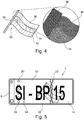
- FIG. 5 A ready-to-use license plate 1 according to the invention is shown in supervision. It is based on the shield blank Fig. 3 , which was provided with a circumferential raised edge 32 and an individual identification legend 34 in a subsequent processing step. Both the edge 32 and the symbols of the license plate legend 34 are raised and produced by means of mechanical stamping of the shield blank 10. After the embossing, the raised embossed areas of the license plate 1, ie the peripheral edge 32 and the identification legend 34, have been permanently colored black by means of a color transfer from a color transfer film in a thermal transfer process.
- Fig. 6 shows a first embodiment of a manufacturing device 100 according to the invention in a schematic representation.
- the device 100 is for Manufacture of a license plate 1 provided and set up. It comprises a blank feed 102 for providing a shield blank 10.
- the blank 10 consists of a (not yet isolated) section of an endless aluminum strip 114 which is unwound from a supply roll 116. These tasks are carried out by the functional unit of the board feeder 110.
- the device 100 comprises a film feed 120 for providing a film 14, for example a retroreflective film with a transparent cover layer as in connection with FIG 1 and 2 explained.
- the film feeder 120 comprises a supply spool 122, on which a supply of the described film 14 is wound up as an endless belt.
- the film structure corresponds to that in connection with Fig. 1 described structure.
- the film 14 to be laminated onto the shield board is unwound and fed to a laminating station 130, in which the film 14 is laminated onto the endless metal strip 114, which is also fed to the laminating station 130.
- a paper liner 128 covering the adhesive layer 16 is pulled off the film 14 and wound onto a take-up roll 126.
- the adhesive layer of the film 14 is further brought into contact with the metal strip 114.
- a (possibly heated) pressure roller 132 arranged in the laminating station 130 applies a defined contact pressure to the film 14 and thus ensures activation of the adhesive layer.
- a punching unit 140 is arranged downstream of the laminating station 130 and cuts individual license plate blanks 10 out of the metallic tape 114, which is laminated with the retroreflective film 14, which are then fed to further processing.
- a mechanical structuring unit 150 in the form of a hot stamping station is arranged between the laminating station 130 assigned to the board supply 110 and the punching unit 140. This is set up to introduce an optically perceptible, extensively extended security structure 30 into the front surface of the shield blank 10, more precisely into the top coat of the retroreflective foil 14 laminated onto the shield plate 12 Security structure 30 a color effect based on optical interference, which is based on regular, raised or recessed structures in the surface of the shield blank 10.
- the structuring unit 150 is in each case set up to produce an optically perceptible security structure 30 which comprises a plurality of discrete surface areas which have at least two different color effects. These different color effects are achieved by, for example, varying the characteristic dimensions of the regular structures, such as the dominant structure spacing.
- the structuring unit 150 comprises a structured metallic stamp (not shown) and is set up to mechanically hot stamp the retroreflective film 14 from the structured stamp into the surface of the top coat of the film 14 and thus of the shield blank 10 by means of mechanical hot stamping transferred to.
- the structuring unit 150 is designed in such a way that the stamping die can be heated, so that it e.g. can be heated to a temperature of over 70 ° C, in particular between 120 ° C and 160 ° C, preferably to 150 ° C.
- the structuring unit 150 is equipped with an additional circuit board heater (not shown) which allows local heating of a shield blank 10 to be embossed in the area in which the security structure 30 is to be mechanically stamped into the surface of the shield blank 10.
- the metallic embossing stamp in turn is provided with a negative of the security structure 30 to be introduced into the surface of the shield blank 10, which is to be molded into the surface of the shield blank 10.
- the structuring of the embossing stamp was generated by means of direct laser interference structuring, ie the structuring of the embossing stamp is based on a structure which was generated by interference from at least two laser beams.
- the two laser beams which can be generated, for example, by beam splitting a laser beam generated by a laser, each have a linear focus. These partial beams are guided that the foci overlap on or in the surface of the previously highly polished stamp, which is made of stainless steel.
- the laser interference structuring of the embossing stamp causes the stamp and the point of incidence of the laser beams on the stamp to be moved relative to one another perpendicularly to the direction of expansion of the foci. It is further provided that an optical mask is imaged on the surface of the stamp in order to form the negative for the optically perceptible, extensively extended security structure on the embossing stamp.
- Fig. 7 shows a second embodiment of a manufacturing device 100 according to the invention again in a schematic representation.
- the manufacturing device 100 according to the second exemplary embodiment corresponds in all its features to the manufacturing device according to the first exemplary embodiment Fig. 6 with the exception of the structuring unit 150, which in this second exemplary embodiment does not work mechanically, but rather is laser-based and therefore contactless.
- the structuring unit 150 comprises a laser (not shown) and is set up to introduce the optically perceptible security structure 30 into the surface of the shield blank 10 by means of interference from at least two laser beams.
- the structuring unit 150 is set up such that the laser beams each have a linear focus and the foci overlap on or in the surface of the shield blank 10 to be structured.
- the laser-based structuring unit 150 is set up to image an optical mask on the surface of the shield blank 10 in order to form the optically perceptible, extensive security structure in the surface of the shield blank 10.
Abstract
Die Erfindung bezieht sich auf ein Kfz-Kennzeichenschild 1, welches ein neuartiges, optisch wahrnehmbares Sicherheitsmerkmal 30 aufweist. Weiterhin bezieht sich die Erfindung auf ein Verfahren zur Herstellung eines solchen Kfz-Kennzeichenschilds 1 sowie eine zur Durchführung des Verfahrens geeignete Herstellvorrichtung 100.The invention relates to a license plate 1, which has a novel, optically perceptible security feature 30. Furthermore, the invention relates to a method for producing such a license plate 1 and a manufacturing device 100 suitable for carrying out the method.
Description
Gegenstand der vorliegenden Erfindung ist ein Verfahren zur Herstellung eines retroreflektierenden Kfz-Kennzeichenschilds, ein gemäß dem Verfahren herstellbares retroreflektierendes Kfz-Kennzeichenschild sowie eine Vorrichtung zur Durchführung des Verfahrens. Insbesondere betrifft die Erfindung ein Herstellverfahren für ein Kfz-Kennzeichenschild mit neuartigen Sicherheitsmerkmalen, eine zur Ausführung dieses Verfahrens geeignete Vorrichtung zur Herstellung eines Kfz-Kennzeichenschilds mit neuartigen Sicherheitsmerkmalen sowie ein Kfz-Kennzeichenschild mit neuartigen Sicherheitsmerkmalen.The present invention relates to a method for producing a retroreflective motor vehicle license plate, a retroreflective motor vehicle license plate that can be produced according to the method and a device for carrying out the method. In particular, the invention relates to a production method for a motor vehicle license plate with novel security features, a device suitable for carrying out this method for producing a motor vehicle license plate with novel security features, and a motor vehicle license plate with novel security features.
Kfz-Kennzeichenschilder mit optisch wahrnehmbaren Sicherheitsmerkmalen sind grundsätzlich seit langem bekannt. Optisch wahrnehmbare Sicherheitsmerkmale werden auch als "Wasserzeichen" bezeichnet. Aus dem Stand der Technik sind Wasserzeichen bekannt, die mittels Druckverfahren erzeugt werden, als auch durch Laserbehandlung erzeugte Wasserzeichen. So hat z.B. die Minnesota Mining & Mfg. Company, Minnesota, USA (handelnd im geschäftlichen Verkehr unter 3M) retroreflektierende Folien zur Herstellung von retroreflektierenden Kfz-Kennzeichen-schildern im Programm, die zweierlei optisch wahrnehmbare Sicherheitsmerkmale umfasst, welche von 3M unter den Bezeichnungen Ensure™ Image und Ensure™ Virtual Security Thread vertrieben werden. Zum Anmeldezeitpunkt handelte es sich hierbei beispielsweise um die Folien der Serien mit der 3M-Produktbezeichnung 4750E sowie 4750T.License plates with optically perceptible security features have been known for a long time. Visually perceptible security features are also referred to as "watermarks". From the prior art, watermarks are known which are generated by means of printing processes, as well as watermarks generated by laser treatment. For example, the Minnesota Mining & Mfg. Company, Minnesota, USA (trading under 3M) retroreflective foils for the production of retroreflective license plates in the program, which includes two optically perceptible security features, which 3M sells under the names Ensure ™ Image and Ensure ™ Virtual Security Thread will. At the time of registration, these were, for example, the films of the series with the 3M product designation 4750E and 4750T.
Als Ensure™ Sicherheitsmerkmal wird eine optische Markierung der Folie bezeichnet, die bei senkrechter Orientierung der Folie nur unter einem Betrachtungswinkel von etwa 30° gegen die Horizontale sichtbar ist. Ansonsten erscheint die Folie einheitlich retroreflektierend, das d.h. das Sicherheitsmerkmal ist unsichtbar. Ein Verfahren zur Herstellung des Ensure™ Image Sicherheitsmerkmals wird z.B. in der
Unter der Bezeichnung Ensure™ Virtual Security Thread wird eine retroreflektierende Folie vermarktet, die ein optisch wahrnehmbares Sicherheitsmerkmal umfasst, welches in das Material der Folie eingebracht ist und dreidimensional erscheint. Es umfasst zwei virtuelle Bilder, von denen eines oberhalb der Ebene des Schilds zu schweben scheint und eines unterhalb. Es ist bei direkter Betrachtung der Folie auch aus größerem Abstand sichtbar und lässt sich auch mit dem Sicherheitsmerkmal Ensure™ Image kombinieren. Weitere Informationen zu retroreflektierenden Folien mit dem Sicherheitsmerkmal Ensure™ Virtual Security Thread ergeben sich auch aus der
Das Sicherheitsmerkmal Ensure™ Virtual Security Thread lässt sich in der Praxis nur bei der Folienherstellung selbst einbringen. Eine Änderung des eingebrachten Sicherheitsmerkmals, z.B. dessen Kontur, ist daher dem Folienhersteller vorbehalten, was die Beschaffung kleinerer Mengen von Folie versehen mit auf Kundenwunsch individualisiertem Sicherheitsmerkmal problematisch und insbesondere kostenintensiv macht. Die Anbringung von auf Kundenwunsch individualisierten Sicherheitsmerkmalen dieser Typen beim Schildhersteller ist damit in der Praxis unmöglich.In practice, the Ensure ™ Virtual Security Thread security feature can only be introduced during film production. A change in the security feature, e.g. its contour is therefore reserved for the film manufacturer, which makes the procurement of smaller quantities of film with a security feature individualized on customer request problematic and in particular cost-intensive. In practice, it is therefore impossible to apply security features of these types that are customized to the customer's requirements at the label manufacturer.
Weiterhin ist die Verwendung von optischen Hologrammsiegeln als Sicherheitsmerkmal bekannt, die in einem separaten Herstellungsverfahren auf einer separaten Trägerfolie erzeugt werden. So bietet die Fa. Leonhard Kurz Stiftung & Co. KG sogenannte Hologrammsiegelfolien an, die einen Polyesterträger umfassen, auf dem ein Lackpaket bestehend aus einer Kleberschicht, einer strukturierten Metallisierung zur Ausbildung des optischen Hologrammsiegels, einer Replizierschicht und einem Schutzlack ablösbar angeordnet ist. Im Rahmen der Herstellung eines Kfz-Kennzeichenschilds werden diese Hologrammsiegel mittels eines Thermotransferverfahrens von der Polyesterfolie auf die Oberfläche des Kfz-Kennzeichenschilds übertragen und mit dessen Oberfläche thermisch verschweißt. Derartige optische Hologrammsiegel sind optisch gut verifizierbar und sind insbesondere auch auf retroreflektierenden Folien ohne metallische Reflexionsschicht anbringbar, also beispielweise auf retroreflektierenden Folien, die auf mikroprismatischen Elementen basieren. Ihre Anbringung auf dem Kfz-Kennzeichenschild ist jedoch technisch aufwendig und erhöht daher die Produktionskosten des Kfz-Kennzeichenschilds. So wird in der Praxis vielfach beobachtet, dass der Polyesterträger des Siegels nach der Übertragung des Siegels auf die Oberfläche des Kfz-Kennzeichenschilds bereichsweise an der Oberfläche des Schilds anhaftet, so dass eine Vorrichtung benötigt wird, die den Polyesterträger wieder vom Kfz-Kennzeichenschilds ablöst. Hierbei besteht zusätzlich das Risiko einer mechanischen Beschädigung der Oberfläche des Kfz-Kennzeichenschilds. Darüber hinaus erhöht die Verwendung derartiger Hologrammsiegel in der Kfz-Kennzeichenschildherstellung die logistischen Anforderungen, da zusätzliche separate Komponenten verwendet werden, die in der Regel von einem weiteren Lieferanten bezogen werden müssen, was sich wiederum nachteilig auf die Produktionskosten auswirkt. Auch der erforderliche Polyesterträger erweist sich in der Praxis als nachteilig. Das Handling des bandförmigen Polyesterträgers in der Zufuhr der Hologrammsiegel als auch in der Rückführung nach dem Siegelprozess ist aufwendig, die hierzu erforderlichen mechanischen Komponenten erfordern relativ viel Platz, so dass eine Integration in bestehende Produktionsanlagen für die Kfz-Kennzeichenschildherstellung problematisch ist. Weiterhin fällt durch den zurückbleibenden Polyesterträger relativ viel Abfall an, was unter Umweltschutzgesichtspunkten nachteilig ist. Weiterhin sind derartige Hologrammsiegel wegen der enthaltenen Metallschicht naturgemäß intransparent, was insbesondere bei retroreflektierenden Kfz-Kennzeichen-schildern zu lokalen Bereichen mit fehlender Retroreflektivität führt, was unerwünscht oder gemäß lokaler Zulassungsvorschriften sogar unzulässig sein kann. Schließlich ist die Produktion von gemäß Kundenanforderung individualisierten Hologrammen teuer, da für jedes individuelle Motiv ein Master für die Hologrammherstellung benötigt wird, welches aufwendig herzustellen ist. Die Erstellung von Kleinserien verbietet sich daher in der Regel aus Kostengründen.Furthermore, the use of optical hologram seals as a security feature is known, which are produced in a separate manufacturing process on a separate carrier film. For example, the Leonhard Kurz Foundation & Co.KG offers so-called hologram sealing foils, which comprise a polyester carrier, on which a lacquer package consisting of an adhesive layer, a structured metallization to form the optical hologram seal, a replication layer and a protective lacquer is removably arranged. As part of the production of a license plate, these hologram seals are transferred from the polyester film to the surface of the license plate using a thermal transfer process and thermally welded to the surface thereof. Optical hologram seals of this type can be easily verified optically and are in particular also on retroreflective foils without metallic ones Reflective layer can be attached, for example on retroreflective foils based on microprismatic elements. However, attaching them to the license plate is technically complex and therefore increases the production costs of the license plate. In practice, it is often observed that the polyester carrier of the seal adheres in some areas to the surface of the license plate after the seal has been transferred to the surface of the license plate, so that a device is required which detaches the polyester carrier from the license plate again. There is also the risk of mechanical damage to the surface of the license plate. In addition, the use of such hologram seals in the production of license plates increases the logistical requirements, since additional separate components are used, which generally have to be obtained from another supplier, which in turn has a disadvantageous effect on the production costs. The required polyester backing also proves to be disadvantageous in practice. The handling of the band-shaped polyester carrier in the supply of the hologram seals as well as in the return after the sealing process is complex, the mechanical components required for this require a relatively large amount of space, so that integration into existing production systems for license plate production is problematic. Furthermore, the remaining polyester carrier produces a relatively large amount of waste, which is disadvantageous from an environmental point of view. Furthermore, such hologram seals are naturally non-transparent because of the metal layer contained therein, which in particular in the case of retroreflective license plate signs leads to local areas with a lack of retroreflectivity, which can be undesirable or even inadmissible according to local approval regulations. Finally, the production of holograms customized according to customer requirements is expensive, since a master for hologram production is required for each individual motif, which is complex to produce. The creation of small series is therefore generally forbidden for reasons of cost.
Aufgabe der vorliegenden Erfindung ist es daher, ein kostengünstiges Verfahren zur Herstellung eines Kfz-Kennzeichenschilds mit integriertem Sicherheitsmerkmal anzugeben, welches kostengünstig ist und die vorgenannten Nachteile vermeidet. Weiterhin ist es Aufgabe der vorliegenden Erfindung, ein vorteilhaftes Kfz-Kennzeichenschild mit integriertem Sicherheitsmerkmal sowie eine zur Ausführung des erfindungsgemäßen Verfahrens geeignete Vorrichtung anzugeben, welche mithin auch zur Herstellung eines erfindungsgemäßen Kfz-Kennzeichen-schilds geeignet ist.The object of the present invention is therefore to provide an inexpensive method for producing a license plate with an integrated security feature, which is inexpensive and avoids the aforementioned disadvantages. Furthermore, it is an object of the present invention to provide an advantageous license plate with an integrated security feature and one for Execution of the method according to the invention to specify a suitable device, which is therefore also suitable for producing a license plate according to the invention.
Gelöst wird diese Aufgabe durch ein Herstellungsverfahren für ein Kfz-Kennzeichenschild gemäß Anspruch 1, ein Kfz-Kennzeichenschild gemäß Anspruch 2 sowie eine Herstellungs-Vorrichtung gemäß Anspruch 13.This object is achieved by a manufacturing method for a license plate according to
Die Unteransprüche betreffen verschiedene voneinander unabhängige, vorteilhafte Weiterbildungen der vorliegenden Erfindung, deren Merkmale von Fachmann im Rahmen des technisch Sinnvollen frei miteinander kombiniert werden können. Dies gilt insbesondere auch über die Grenzen der verschiedenen Anspruchskategorien hinaus.The subclaims relate to various mutually independent, advantageous developments of the present invention, the features of which can be freely combined by one skilled in the art in the context of what is technically sensible. This applies in particular beyond the boundaries of the various claim categories.
Das erfindungsgemäße Verfahren lässt sich oftmals in Form weniger zusätzlicher Verfahrensschritte unmittelbar in bestehende Verfahrensabläufe zur Herstellung von Kfz-Kennzeichenschildern integrieren, ohne Änderungen dieser Verfahrensabläufe erforderlich zu machen. Die mittels des Verfahrens erzeugten Kfz-Kennzeichenschilder weisen ein neuartiges, optisch wahrnehmbares Sicherheitsmerkmal auf, welches auf einer optisch wahrnehmbaren, flächenhaft ausgedehnten Sicherheitsstruktur basiert, die in die vorderseitige Oberfläche des Schildrohlings eingebracht ist und auf regelmäßigen, erhabenen oder vertieften Strukturen in der Oberfläche der Schildrohlings beruht. Diese Kennzeichenschilder bieten daher ein hohes Maß an Fälschungssicherheit, da die das Sicherheitsmerkmal ausbildende Sicherheitsstruktur es integral mit dem Material des Kennzeichenschildrohlings, hier insbesondere mit der Schildplatine oder mit einer auf dieser auflaminierten Kunststofffolie, verbunden ist. Darüber hinaus stehen verschiedene Verfahren zur Erzeugung einer derartigen Sicherheitsstruktur zur Verfügung, die sich insbesondere zu einer Ausführung im Rahmen eines Herstellungsverfahrens für ein Kfz-Kennzeichenschild gemäß Stand der Technik eignen, womit das erfindungsgemäße Verfahren auch direkt beim Schildhersteller anwendbar ist. Diese Verfahren erlauben darüber hinaus eine gute bis hohe Flexibilität bezüglich der eingebrachten Sicherheitsstruktur bezüglich deren Motiv und Größe, deren Anordnung und Ausrichtung auf der Schildplatine sowie deren Farbeindruck, so dass eine Kundenspezifische Individualisierung auch bei Kleinserien wirtschaftlich möglich wird. Schließlich erfordert die neuartige Sicherheitsstruktur keinerlei intransparente, z.B. metallische Reflexionsschicht, so dass sie vorteilhaft auch auf retroreflektierenden Schildrohlingen oder Schildrohlingen angebracht werden kann, die eingebettete zusätzliche, optisch wahrnehmbare Sicherheitsmerkmale wie z.B. die vorbeschriebenen Sicherheitsmerkmale Ensure™ Image oder Ensure™ Virtual Security Thread aus dem Hause 3M umfassen, ohne diese durch Überdeckung unlesbar bzw. unerkennbar und damit unwirksam zu machen.The method according to the invention can often be integrated in the form of a few additional method steps directly into existing method sequences for the production of motor vehicle license plates, without requiring changes to these method sequences. The vehicle license plates produced by the method have a novel, optically perceptible security feature, which is based on an optically perceptible, extensively extended security structure, which is incorporated into the front surface of the blank plate and on regular, raised or recessed structures in the surface of the blank plate is based. These license plates therefore offer a high level of protection against counterfeiting, since the security structure forming the security feature is integrally connected to the material of the license plate blank, in particular here to the label plate or to a plastic film laminated thereon. In addition, various methods for generating such a security structure are available, which are particularly suitable for execution within the scope of a manufacturing method for a license plate for vehicles according to the prior art, with which the method according to the invention can also be used directly by the label manufacturer. These processes also allow good to high flexibility with regard to the security structure introduced with regard to its motif and size, its arrangement and orientation on the plate and its color impression, so that customer-specific individualization is economically possible even in small series. Finally, the new security structure requires no non-transparent, e.g. metallic reflective layer, so that it can also be advantageously applied to retroreflective shield blanks or shield blanks that include embedded additional, optically perceptible security features such as the above-described security features Ensure ™ Image or Ensure ™ Virtual Security Thread from 3M, without them to make them illegible or unrecognizable and thus ineffective by covering them.
Ein erfindungsgemäßes Verfahren ist zur Herstellung eines Kfz-Kennzeichenschilds vorgesehen. In seiner einfachsten Ausprägung umfasst es den Verfahrensschritt des Bereitstellens eines flächenhaft ausgedehnten Schildrohlings, z.B. einer Schildplatine aus Kunststoff oder einer metallischen Schildplatine mit auflaminierter eingefärbter Kunststofffolie. Insbesondere kann es sich bei einem Schildrohling bereits um ein gebrauchsfertiges Kfz-Kennzeichenschild handeln, welches im Rahmen des erfindungsgemäßen Verfahrens nur noch mit der erfindungsgemäßen Sicherheitsstruktur versehen wird.A method according to the invention is provided for the production of a license plate. In its simplest form, it comprises the step of providing a blank shield, e.g. a shield plate made of plastic or a metallic shield plate with laminated colored plastic film. In particular, a blank plate can already be a ready-to-use vehicle license plate, which is only provided with the security structure according to the invention within the scope of the method according to the invention.
Erfindungsgemäß wird nun auf geeignete Weise in die vorderseitige Oberfläche des Schildrohlings eine optisch wahrnehmbare, insbesondere flächenhaft ausgedehnte Sicherheitsstruktur eingebracht. Hierunter sollen Verfahren fallen, die das Material des Schildrohlings an dessen vorderseitigen Oberfläche entweder lokal umformen oder lokal abtragen. Explizit nicht unter diese Formulierung sollen Verfahren fallen, bei denen zusätzliches Material auf die vorderseitige Oberfläche des Schildrohlings aufgebracht wird.According to the invention, an optically perceptible, in particular extensive security structure is now introduced into the front surface of the shield blank in a suitable manner. This should include processes that either locally deform the material of the shield blank on its front surface or remove it locally. This formulation should not explicitly include processes in which additional material is applied to the front surface of the shield blank.
Diese erfindungsgemäß eingebrachte Sicherheitsstruktur umfasst flächenhaft ausgedehnte, regelmäßige, erhabene oder vertiefte Strukturen in der Oberfläche des Schildrohlings, die so ausgestaltet sind, dass die eingebrachte Sicherheitsstruktur einen auf optischer Interferenz beruhenden optischen Effekt, insbesondere Farbeffekt, zeigt. Die regelmäßigen Abstände der eingebrachten Strukturen liegen daher vorteilhaft in der Größenordnung der Wellenlänge sichtbaren Lichts, insbesondere im Bereich zwischen 150 Nanometern und 30 Mikrometern, besonders bevorzugt zwischen 450 und 1500 Nanometern.This security structure introduced according to the invention comprises extensive, regular, raised or recessed structures in the surface of the shield blank, which are designed in such a way that the security structure introduced has an optical effect based on optical interference, in particular a color effect. The regular distances between the structures introduced are therefore advantageously of the order of magnitude of the wavelength of visible light, in particular in the range between 150 nanometers and 30 micrometers, particularly preferably between 450 and 1500 nanometers.
Im Rahmen der vorliegenden Erfindung kann die dominante Strukturgröße der eingebrachten Mikrostruktur im o.g. Rahmen auf Kundenbedürfnisse zugeschnitten werden. So können Mikrostrukturen erzeugt werden, die unter bestimmten Winkeln durch konstruktive Interferenz im sichtbaren Bereich reflektieren und daher unmittelbar mit dem menschlichen Auge als farbige Bilder wahrnehmbar sind. Es können jedoch auch Mikrostrukturen erzeugt werden, die in Wellenlängenbereichen reflektieren, welche für das menschliche Auge unsichtbar sind, z.B. im UV oder im nahen IR. Derartige Strukturen sind für eine maschinelle Echtheitsprüfung prädestiniert.In the context of the present invention, the dominant structure size of the introduced microstructure can be tailored to customer needs within the above-mentioned framework. In this way, microstructures can be created that are under certain Reflect angles through constructive interference in the visible range and are therefore directly perceptible as colored images with the human eye. However, microstructures can also be generated which reflect in wavelength ranges which are invisible to the human eye, for example in the UV or in the near IR. Structures of this type are predestined for machine authenticity checking.
In einer ersten vorteilhaften Weiterbildung weist der Schildrohling retroreflektierende Eigenschaften auf. Besonders bevorzugt basieren diese retroreflektierenden Eigenschaften auf in den Schildrohling eingebetteten bzw. integral mit diesem ausgebildeten (mikro)prismatischen Elementen.In a first advantageous development, the shield blank has retroreflective properties. These retroreflective properties are particularly preferably based on (micro) prismatic elements embedded in the shield blank or formed integrally therewith.
In einer weiteren vorteilhaften Weiterbildung, die alternativ oder ergänzend zu der vorgenannten ersten vorteilhaften Weiterbildung anzuwenden ist, weist der Schildrohling ein zusätzliches optisch wahrnehmbares Sicherheitsmerkmal auf, welches in das Material des Schildrohlings eingebettet ist. Hierbei kann es sich beispielsweise um die vorgenannten Sicherheitsmerkmale handeln, die von der Fa. 3M unter den Bezeichnungen Ensure™ Image bzw. Ensure™ Virtual Security Thread angeboten werden. Hierzu ist umfasst der Schildrohling eine z.B. metallische Schildplatine, die mit einer retroreflektierenden Folie der Fa. 3M eines der Typen 4750E oder 4750T kaschiert ist, d.h. eine solche Folie ist auf die Vorderfläche der Schildplatine auflaminiert.In a further advantageous development, which is to be used as an alternative or in addition to the aforementioned first advantageous development, the shield blank has an additional optically perceptible security feature which is embedded in the material of the shield blank. This can be, for example, the aforementioned security features, which 3M offers under the names Ensure ™ Image or Ensure ™ Virtual Security Thread. For this purpose, the shield blank comprises e.g. metallic shield plate, which is laminated with a retroreflective foil from 3M of one of the types 4750E or 4750T, i.e. such a film is laminated onto the front surface of the shield plate.
Im Zusammenhang mit den vorgenannten vorteilhaften Weiterbildungen ergeben sich besondere Vorteile, wenn die erfindungsgemäße, optisch wahrnehmbare Sicherheitsstruktur in solchen Bereichen des Kfz-Kennzeichenschilds angeordnet wird,
- a) in denen der Schildrohling retroreflektierende Eigenschaften aufweist, oder
- b) unterhalb derer das in das Material des Schildrohlings eingebettete, optisch wahrnehmbare zusätzliche Sicherheitsmerkmal angeordnet ist.
- a) in which the shield blank has retroreflective properties, or
- b) below which the visually perceptible additional security feature is arranged, which is embedded in the material of the shield blank.
Da das erfindungsgemäße Sicherheitsmerkmal nur unter bestimmten Winkeln konstruktive Interferenz zeigt und damit dem Beobachter nur unter bestimmten Winkeln als farbige Struktur erscheint, ist das erfindungsgemäße Sicherheitsmerkmal bei senkrechter Aufsicht auf den Schildrohling (bzw. das gebrauchsfertige Kfz-Kennzeichenschild) im Wesentlichen unsichtbar bzw. transparent. Wird es in oder auf der Oberfläche einer transparenten Schicht ausgebildet, die z.B. aus einem Kunststoff bestehen kann, so bleiben durch die transparente Schicht hindurch optisch wahrnehmbare Eigenschaften der Folie bzw. des Schildrohlings wie z.B. in die Folie eingebettete zusätzliche Sicherheitsmerkmale oder eine Retroreflektivität weitestgehend erhalten. Insbesondere bedeutet dies, dass es möglich ist, die erfindungsgemäße Sicherheitsstruktur großflächig auszubilden, insbesondere so groß, dass sich die Sicherheitsstruktur im Wesentlichen über die gesamte Oberfläche des Schildrohlings erstreckt. Dies stellt einen besonderen Vorteil der mittels der erfindungsgemäßen Sicherheitsstruktur und damit eines mit einer solchen ausgerüsteten Kfz-Kennzeichenschilds dar.Since the security feature according to the invention only shows constructive interference at certain angles and thus only appears to the observer as a colored structure at certain angles, the security feature according to the invention is essentially invisible or transparent when viewed vertically onto the blank plate (or the ready-to-use license plate). Becomes If it is formed in or on the surface of a transparent layer, which can consist, for example, of a plastic, optically perceptible properties of the film or of the shield blank, such as additional security features embedded in the film or retroreflectivity, are largely retained through the transparent layer. In particular, this means that it is possible to design the security structure according to the invention over a large area, in particular so large that the security structure extends essentially over the entire surface of the shield blank. This represents a particular advantage of the security structure according to the invention and thus of a license plate equipped with such a license plate.
Im weiteren Verfahrensgang zur Herstellung eines gebrauchsfertigen individualisierten Kfz-Kennzeichenschilds wird der Schildrohling mit einer individuellen Kennzeichenlegende versehen, die z.B. auf die vorderseitige Oberfläche aufgedruckt sein kann. Alternativ kann die Kennzeichenlegende bei Verwendung eines prägefähigen Materials für den Schildrohling auch in den Schildrohling geprägt sein, z.B. als erhabene Prägung. Eine geprägte Kennzeichenlegende kann auch zusätzlich eingefärbt sein, was insbesondere mittels eines Übertrags von einer Heißprägefolie in einem Thermotransferverfahren oder mittels Abwalzen mit einer Farbwalze möglich ist. Eine Kennzeichenlegende kann aber auch durch Anbringung von separat ausgebildeten individuellen Zeichen auf der vorderseitigen Oberfläche des Schildrohlings ausgebildet werden.In the further process for producing a ready-to-use, individualized license plate, the blank plate is provided with an individual license plate legend, e.g. can be printed on the front surface. Alternatively, the label legend can also be embossed in the shield blank when using an embossable material for the shield blank, e.g. as a raised imprint. An embossed license plate legend can also be colored, which is possible in particular by means of transfer from a hot stamping foil in a thermal transfer process or by rolling with an ink roller. A label legend can also be formed by attaching separately formed individual characters on the front surface of the blank plate.
Im Kontext der vorliegenden Anmeldung wird unter einem Kfz-Kennzeichenschild grundsätzlich ein Schild verstanden, welches bereits mit einer individuellen Kennzeichenlegende versehen ist. Als Kennzeichenrohling wird hingegen ein Schild verstanden, welches noch nicht mit einer individuellen Kennzeichenlegende versehen ist. Ist in den Ansprüchen jedoch von einem Kfz-Kennzeichenschild die Rede, so soll diese Formulierung sowohl ein gebrauchsfertiges, mit einer Kennzeichenlegende individualisiertes Kfz-Kennzeichenschild umfassen als auch einen Kennzeichenrohling im vorgenannten Sinne. Hiermit soll insbesondere klargestellt werden, dass im Rahmen der vorliegenden Erfindung die Einbringung der erfindungsgemäßen Sicherheitsstruktur in die vorderseitige Oberfläche sowohl an einem Schildrohling als auch an einem gebrauchsfertigen, mit einer Kennzeichenlegende individualisierten Kfz-Kennzeichenschild möglich ist. Dies bezieht sich insbesondere auf das erfindungsgemäße Verfahren gemäß Anspruch 1 als auch auf das erfindungsgemäße Kfz-Kennzeichenschild gemäß Anspruch 2, wobei sich der Schutz aus letzterem explizit auch auf Schildrohlinge im oben genannten Sinne erstrecken soll.In the context of the present application, a vehicle license plate is basically understood to be a label which is already provided with an individual license plate legend. A license plate blank, on the other hand, is understood to be a label that has not yet been provided with an individual license plate legend. However, if the claims refer to a license plate, this wording should encompass both a ready-to-use, individualized license plate legend and a blank license plate in the aforementioned sense. This is intended in particular to make it clear that, within the scope of the present invention, the security structure according to the invention can be introduced into the front surface both on a blank plate and on a ready-to-use vehicle license plate that is individualized with a label legend. This relates in particular to the inventive method according to
In einer vorteilhaften Ausprägung des erfindungsgemäßen Verfahrens werden zur Bereitstellung eines Schildrohlings die folgenden Verfahrensschritte ausgeführt:
- a) Bereitstellen einer Schildplatine,
- b) Bereitstellen einer Folie mit einer transparenten Deckschicht, und
- c) Auflaminieren der Folie auf die Schildplatine, so dass die transparente Deckschicht der Folie die vorderseitige Oberfläche des Schildrohlings ausbildet.
- a) providing a shield board,
- b) providing a film with a transparent cover layer, and
- c) laminating the film onto the shield board so that the transparent cover layer of the film forms the front surface of the shield blank.
Dabei kann das Einbringen der optisch wahrnehmbaren Sicherheitsstruktur in die Folie sowohl vor als auch nach dem Auflaminieren der Folie durchgeführt werden.The optically perceptible security structure can be introduced into the film both before and after the film is laminated on.
Dabei kann die Folie vorteilhaft eingefärbt sein, z.B. um nationalen Zulassungsvorschriften zu entsprechen.The film can advantageously be colored, e.g. to comply with national approval regulations.
Sie kann darüber hinaus bereits bereichsweise farbig bedruckt sein, z.B. mit einem die spätere Kennzeichenlegende umgreifenden umlaufenden Rahmen. Auch Hoheitszeichen oder auch dekorative Elemente können bereits aufgedruckt sein.In addition, it can already be color-printed in some areas, e.g. with a surrounding frame that encompasses the later license plate legend. National emblems or decorative elements can also be printed on.
In einer besonders bevorzugten Ausgestaltung weist die Folie, welche auf die Schildplatine auflaminiert wird, retroreflektierende Eigenschaften auf. Insbesondere kann es sich um eine Folie mit in einer transparenten Kunststoffschicht eingebetteten Mikrolinsen und dahinterliegender Reflexionsschicht handeln, oder um eine Folie mit in einer transparenten Kunststoffschicht eingebetteten mikroprismatischen Elementen. In beiden Folientypen kann oberhalb der Mikrolinsen bzw. der mikroprismatischen Elemente eine weitere transparente Schicht z.B. aus einem geeigneten Kunststoff angeordnet sein.In a particularly preferred embodiment, the film which is laminated onto the shield plate has retroreflective properties. In particular, it can be a film with microlenses embedded in a transparent plastic layer and a reflection layer behind it, or a film with microprismatic elements embedded in a transparent plastic layer. In both types of film, a further transparent layer can be placed above the microlenses or the microprismatic elements, e.g. be arranged from a suitable plastic.
Weiterhin kann die Folie, welche auf die Schildplatine auflaminiert wird, mit zusätzlichen Sicherheitsmerkmalen ausrüstet sein, die insbesondere für eine visuelle bzw. optische Überprüfung geeignet sind. So kann die Folie beispielsweise mit den von der Fa. 3M angebotenen Sicherheitsmerkmalen Ensure™ Image oder/und Ensure Ensure™ Virtual Security Thread ausgerüstet sein. Aber auch Folien anderer Folienhersteller, die alternative Sicherheitsmerkmale aufweisen, können vorteilhaft verwendet werden. Schließlich ist es möglich, dass die aufzulaminierende oder bereits auflaminierte Folie vom Anwender des erfindungsgemäßen Verfahrens mit zusätzlichen, vorteilhaft optisch erkennbaren Sicherheitsmerkmalen, ausgerüstet wird, z.B. gemäß der Lehre der vorgenannten
In einer bevorzugten ersten Ausgestaltung des erfindungsgemäßen Verfahrens wird die optisch wahrnehmbare Sicherheitsstruktur mittels mechanischen Prägens, insbesondere mittels Heißprägens, von einem strukturierten Stempel oder einer strukturierten Walze in die vorderseitige Oberfläche des Schildrohlings übertragen. Dabei kann der Stempel oder die Walze insbesondere aus einem Metall, vorzugsweise einem geeigneten Stahl, insbesondere Edelstahl, gefertigt sein, oder auch aus einem geeigneten keramischen Werkstoff. Auch Nickel hat sich besonders bewährt, insbesondere bei der Herstellung von Sleeves, d.h. von hülsenartigen Prägeformen, die i.A. zum Aufschieben auf Prägewalzen vorgesehen sind. Darüber hinaus sind auch beschichtete metallische Materialien grundsätzlich einer Mikrostrukturierung zugänglich und können daher im Rahmen des erfindungsgemäßen Verfahrens für Prägestempel oder -walzen verwendet werden. Zur Vereinfachung wird im Folgenden stets nur von Prägestempeln gesprochen. Diese Formulierung soll aber explizit auch Prägewalzen und Sleeves mit umfassen.In a preferred first embodiment of the method according to the invention, the optically perceptible security structure is transferred from a structured stamp or a structured roller into the front surface of the shield blank by means of mechanical stamping, in particular by means of hot stamping. The punch or the roller can in particular be made of a metal, preferably a suitable steel, in particular stainless steel, or also of a suitable ceramic material. Nickel has also proven particularly useful, particularly in the manufacture of sleeves, i.e. of sleeve-like embossing forms, which i.A. are intended to be pushed onto embossing rollers. In addition, coated metallic materials are fundamentally accessible to microstructuring and can therefore be used for stamping dies or rollers in the process according to the invention. To simplify matters, only stamps are used in the following. However, this wording should also explicitly include embossing rollers and sleeves.
Werden metallische Werkstoffe für den Prägestempel verwendet, so hat es sich bewährt, diesen vor der Strukturierung Hochglanzzupolieren, insbesondere wenn der Stempel mittels Laserstrukturierung strukturiert wird, worauf im Folgenden noch eingegangen wird.If metallic materials are used for the embossing stamp, it has proven useful to polish it to a high gloss before structuring, in particular if the stamp is structured by means of laser structuring, which will be discussed in the following.
Der bevorzugte Temperaturbereich für das Heißprägen wird wesentlich von den für den Schildrohling verwendeten Materialen bestimmt. Typische Heißprägetemperaturen liegen zwischen 70°C und 180°C, wobei Temperaturen um 150°C bevorzugt werden. Die letztgenannten Temperaturen haben sich insbesondere bei der Prägung von Schildrohlingen bewährt, die eine auf eine Schildplatine auflaminierte Kunststofffolie umfassen. Insbesondere vorteilhaft ist diese Temperatur vorteilhaft bei der Verwendung handelsüblicher retroreflektierender Folien für die Kfz-Kennzeichenschildherstellung, wie sie z.B. von den Herstellern 3M, Avery und Orafol vielfältig angeboten werden.The preferred temperature range for hot stamping is largely determined by the materials used for the shield blank. Typical hot stamping temperatures are between 70 ° C and 180 ° C, with temperatures around 150 ° C being preferred. The latter temperatures have proven particularly useful when embossing shield blanks, which comprise a plastic film laminated onto a shield plate. This temperature is particularly advantageous when using commercially available retroreflective films for the Vehicle license plate production, such as those offered by manufacturers 3M, Avery and Orafol.
Typische Prägedrücke liegen bei maximal 10 Tonnen bei einer Prägefläche von 20 x 20 mm2, in der Regel sind aber - insbesondere beim Heißprägen - bereits geringere Drücke im Bereich von 1 bis 2 Tonnen ausreichend.Typical embossing pressures are a maximum of 10 tons with an embossing area of 20 x 20 mm 2 , but generally lower pressures in the range of 1 to 2 tons are sufficient, especially for hot stamping.
Die Verwendung von Prägewalzen erlaubt einen kontinuierlichen Prägeprozess, mit dem z.B. bandartige Sicherheitsstrukturen analog zu dem Ensure™ Virtual Security Thread der Fa. 3M erzeugt werden. In einer bevorzugten Ausgestaltung des Verfahrens wird die erfindungsgemäße Sicherheitsstruktur daher mittels Abwalzen der Oberfläche des Schildrohlings mit einer strukturierten Prägewalze oder einem Sleeve erzeugt.The use of embossing rollers enables a continuous embossing process, e.g. tape-like security structures are created analogously to the Ensure ™ Virtual Security Thread from 3M. In a preferred embodiment of the method, the security structure according to the invention is therefore produced by rolling the surface of the shield blank with a structured embossing roller or a sleeve.
Die Verwendung von Prägestempeln erlaubt es, auch großflächige Sicherheitsstrukturen zu erzeugen, die durch Prägen mittels mehrerer Stempel erzeugt werden können. Dabei kann insbesondere eine gleichzeitige Prägung mittels mehrerer Stempel mittels einer Prägepresse erfolgen, was die Effizienz des Verfahrens erhöht. Dabei müssen die Prägestempel nicht aneinander angrenzen, sondern können auch beabstandet voneinander angeordnet werden, z.B. um zugleich Prägungen in allen vier Ecken des Schildrohlings vorzunehmen. Besondere Vorteile ergeben sich bei der Verwendung verschiedener Prägestempel, wenn sich diese bezüglich des eingebrachten Motivs bzw. der eingebrachten Struktur zu einem Gesamtmotiv oder einer Gesamtstruktur ergänzen, z.B. gemeinschaftlich die vier Ecken eines Rechtecks ausbilden.The use of embossing stamps also makes it possible to produce large-area security structures which can be produced by embossing using a plurality of stamps. In particular, simultaneous embossing by means of a plurality of stamps can take place using an embossing press, which increases the efficiency of the method. The dies do not have to adjoin one another, but can also be arranged at a distance from one another, e.g. to simultaneously emboss in all four corners of the shield blank. Particular advantages result from the use of different embossing stamps if they complement one another in terms of the motif or structure introduced, for example an overall motif or structure. jointly form the four corners of a rectangle.
Um die erfindungsgemäße Sicherheitsstruktur mittels eines mechanischen Prägeverfahrens zu erzeugen ist es erforderlich, dass das die Oberfläche des Schildrohlings ausbildende Material, z.B. die oberste Lage einer auf eine Schildplatine auflaminierten Kunststofffolie oder das Material des Schildrohlings selbst, mechanisch prägbar ist. Besonders bevorzugt ist das Material heißprägefähig, d.h. unter Einwirkung von Wärme prägefähig.In order to create the security structure according to the invention by means of a mechanical stamping process, it is necessary that the material forming the surface of the shield blank, e.g. the top layer of a plastic film laminated onto a shield board or the material of the shield blank itself can be mechanically embossed. The material is particularly preferably hot-stampable, i.e. Embossable under the influence of heat.
Grundsätzlich ist sowohl eine direkte Strukturierung des Prägestempels mittels eines geeigneten Strukturierungsverfahrens, welches unmittelbar auf den Prägestempel einwirkt, als auch eine indirekte Strukturierung möglich. Unter indirekter Strukturierung ist zu verstehen, dass mittels eines geeigneten Strukturierungsverfahrens ein Negativ des gewünschten Prägestempels erzeugt wird, welches dann in einem nachfolgenden Verfahrensschritt in die Oberfläche des Prägestempels unter Ausbildung des gewünschten Positivs übertragen wird.In principle, both a direct structuring of the embossing stamp by means of a suitable structuring method, which acts directly on the embossing stamp, and an indirect structuring is possible. Indirect structuring is understood to mean that by means of a suitable Structuring method a negative of the desired stamp is generated, which is then transferred to the surface of the stamp in a subsequent process step to form the desired positive.
Bevorzugt wird die Strukturierung des Stempels mittels direkter oder indirekter Laserstrukturierung eines Werkstücks aus einem für eine Verwendung als Prägestempel geeigneten Werkstoff erzeugt. Hierbei soll unter "direkter Laserstrukturierung" verstanden werden, dass die zur Strukturierung verwendete Laserstrahlung unmittelbar auf den Stempel einwirkt und dort die beim Prägen in das zu prägende Material abgeformte mechanische Struktur erzeugt. Unter "indirekter Laserstrukturierung" soll hingegen verstanden werden, dass die zur Strukturierung verwendete Laserstrahlung unmittelbar auf einen geeigneten Negativstempel einwirkt und dort eine mechanische Struktur erzeugt. Diese wird dann auf geeignete Weise als Positiv in die Oberfläche des Prägestempels übertragen, wodurch die beim Prägen in das zu prägende Material abgeformte mechanische Struktur erzeugt wird. Insbesondere kann die Strukturierung des Stempels oder des Negativstempels auf einer Struktur basieren, die mittels Interferenz von zumindest zwei Laserstrahlen erzeugt wird. Eine derartige Strukturierung wird im Kontext der vorliegenden Erfindung auch als "Laserinterferenzstrukturierung" bezeichnet.The structuring of the stamp is preferably produced by means of direct or indirect laser structuring of a workpiece from a material suitable for use as an embossing stamp. In this context, “direct laser structuring” is to be understood to mean that the laser radiation used for structuring acts directly on the stamp and there produces the mechanical structure which is molded into the material to be embossed. By contrast, “indirect laser structuring” is to be understood to mean that the laser radiation used for structuring acts directly on a suitable negative stamp and generates a mechanical structure there. This is then transferred in a suitable manner as a positive into the surface of the stamping die, as a result of which the mechanical structure which is molded into the material to be stamped is produced. In particular, the structuring of the stamp or of the negative stamp can be based on a structure which is generated by means of interference from at least two laser beams. Such structuring is also referred to in the context of the present invention as "laser interference structuring".
Beispielhaft wird in diesem Zusammenhang auf die
Zur Laserinterferenzstrukturierung hat sich insbesondere die Verwendung von gepulster Laserstrahlung bewährt. Zu besonders geeigneten Wellenlängen, Pulsdauern, Pulsrepetitionsraten sowie Pulsenergien wird nochmals auf die Offenbarung der
Überraschend hat sich gezeigt, dass auch eine durch Prägung des Schildrohlings mit direkt laserinterferenzstrukturiertem Stempel z.B. gemäß der Lehre
In einer alternativen vorteilhaften Ausgestaltung des erfindungsgemäßen Verfahrens wird die optisch wahrnehmbare Sicherheitsstruktur mittels direkter Laserstrukturierung in die vorderseitige Oberfläche des Schildrohlings eingebracht, die insbesondere auf der Interferenz von zumindest zwei Laserstrahlen auf / in der Oberfläche des Schildrohlings basiert.In an alternative advantageous embodiment of the method according to the invention, the optically perceptible security structure is introduced into the front surface of the shield blank by means of direct laser structuring, which is based in particular on the interference of at least two laser beams on / in the surface of the shield blank.
Ein entsprechendes Verfahren, welches sich insbesondere zur direkten Laserinterferenzstrukturierung von Schildrohlingen mit einer erfindungsgemäßen Sicherheitsstruktur eignet, ist beispielsweise wiederum aus der
In einer besonders vorteilhaften Weiterbildung des erfindungsgemäßen Verfahrens werden zwei separate Sicherheitsstrukturen in den Schildrohling eingebracht. Eine erste Struktur, die insbesondere großflächig sein kann, wird mittels mechanischen Prägens in die Oberfläche des Schildrohlings eingebracht. Da diese Struktur auf einem Prägestempel basiert, kann sie nicht ohne erheblichen Aufwand von Schildrohling zu Schildrohling variiert werden, vielmehr wird sie über eine größere Zahl von Schildrohlingen (d.h. einige zig bis einige zehntausend) konstant gehalten werden. Eine zweite Struktur wird hingegen mittels Laserstrukturierung erzeugt. Insbesondere wenn hierzu Gebrauch gemacht wird von dem aus der
Es hat sich sowohl bei der direkten Laserinterferenzstrukturierung von Schildrohlingen als auch bei der direkten oder indirekten Laserinterferenzstrukturierung von Stempeln jeweils mittels zumindest zweier Laserstrahlen als vorteilhaft erwiesen, wenn die Laserstrahlen jeweils einen linienhaften Fokus aufweisen und sich die Foki der Laserstrahlen auf bzw. in der Oberfläche des Stempels bzw. der vorderseitigen Oberfläche des Schildrohlings überlagern.It has proven to be advantageous both in the direct laser interference structuring of shield blanks and in the direct or indirect laser interference structuring of stamps by means of at least two laser beams if the laser beams each have a linear focus and the foci of the laser beams are on or in the surface of the Overlay the stamp or the front surface of the shield blank.
Weiterhin hat es sich als vorteilhaft erwiesen, wenn bei der Laserinterferenzstrukturierung von Stempel bzw. Schildrohling mittels zumindest zweier sich überlagernder Laserstrahlen der Stempel bzw. der Schildrohling und der Auftreffpunkt der Laserstrahlen auf dem Stempel bzw. dem Schildrohling senkrecht zur Ausdehnungsrichtung der Foki relativ zueinander bewegt werden. Hierzu kann insbesondere vorgesehen werden, den Schildrohling bzw. den Stempel zu bewegen. Insbesondere kann hier bei der Laserinterferenzstrukturierung der Schildrohlingen Gebrauch gemacht werden von einer ggf. vorliegenden linearen Bewegung der Schildrohlinge während ihrer Herstellung auf einer entsprechenden Produktionsanlage.Furthermore, it has proven to be advantageous if in the laser interference structuring of the stamp or shield blank by means of at least two superimposed laser beams, the stamp or shield blank and the point of incidence of the laser beams on the stamp or shield blank are moved relative to one another perpendicular to the direction of expansion of the foci . For this purpose, provision can be made in particular to move the blank plate or the stamp. In particular, in the case of the laser interference structuring of the shield blanks, use can be made of any linear movement of the shield blanks which may be present during their manufacture on a corresponding production system.
In einer vorteilhaften Weiterbildung des Verfahrens zur Laserinterferenzstrukturierung von Stempel oder Schildrohling zur Ausbildung der optisch wahrnehmbaren, flächenhaft ausgedehnten Sicherheitsstruktur wird eine Maske auf die Oberfläche des Stempels bzw. des Schildrohlings abgebildet. Diese Maske ist für die zur Laserinterferenzstrukturierung verwendete Laserstrahlung im Wesentlichen undurchlässig. Sie kann insbesondere auf einem metallischen Werkstoff basieren. Insbesondere hat sich die Verwendung von Masken bewährt, die als strukturierte metallische Schichten ausgebildet sind, die sowohl freitragend in Form einer Folie ausgebildet sein als auch von einem optisch transparenten Träger wie einem Glassubstrat getragen werden können.In an advantageous development of the method for laser interference structuring of stamps or shield blanks to form the optically perceptible, extensively extended security structure, a mask is imaged on the surface of the stamp or of the shield blank. This mask is essentially opaque to the laser radiation used for laser interference structuring. In particular, it can be based on a metallic material. In particular, the use of masks which are designed as structured metallic layers, which are designed to be self-supporting in the form of a film and can also be carried by an optically transparent carrier such as a glass substrate, has proven useful.
In einer besonders bevorzugten Weiterbildung des erfindungsgemäßen Verfahrens umfasst die optisch wahrnehmbare Sicherheitsstruktur eine Mehrzahl diskreter Oberflächenbereiche, die - unter einem festen Winkel betrachtet - zumindest zwei verschiedene Farbeffekte aufweisen. Verschiedene Farbeffekte lassen sich durch z.B. Variation der charakteristischen Abmessungen der regelmäßen Strukturen wie z.B. des dominanten Strukturabstands erzielen.In a particularly preferred development of the method according to the invention, the optically perceptible security structure comprises a plurality of discrete surface areas which, when viewed at a fixed angle, have at least two different color effects. Different color effects can be achieved by, for example, varying the characteristic dimensions of the regular structures, such as the dominant structure spacing.
Insbesondere ist es auf diese Weise möglich, eine Sicherheitsstruktur, die die Form eines Symbols, eines Logos, etc. aufweist, in einzelne Pixel aufzulösen und auf diese Weise das Symbol bzw. das Logo zumindest zweifarbig dazustellen.In particular, it is possible in this way to resolve a security structure, which has the form of a symbol, a logo, etc., into individual pixels and in this way to present the symbol or the logo at least in two colors.
Darüber hinaus ist es möglich, die Zahl der verschiedenen Farbeffekte weiter zu erhöhen, um die Farbtiefe der erzeugten Sicherheitsstruktur, insbesondere also des dargestellten Symbols oder Logos zu erhöhen.In addition, it is possible to further increase the number of different color effects in order to increase the color depth of the security structure generated, in particular the symbol or logo shown.
Hierzu können z.B. acht oder sechzehn formidentische, regelmäßige Strukturen wie z.B. Kreise, Rechtecke, Sechs- oder Achtecke etc. verwendet werden, die sich nur in ihren dominanten Strukturgrößen unterschieden. Auf diese Weise kann eine Farbtiefe von 8 bzw. 16 Bit erzielt werden.For this, e.g. eight or sixteen identical, regular structures such as Circles, rectangles, hexagons or octagons etc. are used, which differ only in their dominant structure sizes. In this way, a color depth of 8 or 16 bits can be achieved.
Ein noch größeres Farbspektrum kann erschlossen werden, wenn jeder für das Auge eines menschlichen Betrachters sichtbare Bildpunkt aus drei oder mehr formidentischen, regelmäßigen Strukturen zusammengesetzt wird, die sich nur in ihren dominanten Strukturgrößen unterschieden und auf diese Weise - wiederum unter einem festen Winkel betrachtet - drei oder mehr verschiedene Farbeindrücke erzeugen. Aus der Überlagerung dieser drei Grundfarben lässt sich für das menschliche Auge das gesamte sichtbare Farbspektrum erzeugen. Insbesondere bieten sich hier die Farben rot, grün und blau an (RGB-Farbsystem). Ab auch andere Farbsysteme wie CYMK können verwendet werden. Es muss jedoch beachtet werden, dass die zur Bilderzeugung verwendeten Pixel tatsächlich nur unter einem vorgegebenen Betrachtungswinkel in den angegebenen Farben erscheinen.An even larger color spectrum can be developed if each pixel that is visible to the eye of a human viewer is composed of three or more regular structures that are identical in shape and differ only in their dominant structure sizes and in this way - again viewed at a fixed angle - three or create more different color impressions. The entire visible color spectrum can be created for the human eye by superimposing these three basic colors. The colors red, green and blue are particularly suitable here (RGB color system). Ab also other color systems such as CYMK can be used. However, it must be noted that the pixels used for image generation actually only appear in the specified colors from a given viewing angle.
Das erfindungsgemäße Verfahren erlaubt es insbesondere, die mit der Anbringung der aus dem Stand der Technik vorbekannten Hologrammsiegel verbundenen Nachteile zu vermeiden. So fällt kein Abfall an, der entsorgt werden muss, und es werden keine potentiell gesundheitsrelevanten Stoffe z.B. aus einem erhitzten Heißkleber frei. Auch ist der Platzbedarf zumindest bei einer mechanischen Prägung der erfindungsgemäßen Sicherheitsstruktur minimal, so dass das Prägeverfahren ohne weiteres in bestehende Produktionsanlagen für die Herstellung von Schildrohlingen integriert werden kann.The method according to the invention in particular makes it possible to avoid the disadvantages associated with the application of the hologram seals known from the prior art. This means that there is no waste that has to be disposed of, and no potentially health-relevant substances, e.g. free from a heated hot glue. The space requirement is also minimal, at least in the case of mechanical embossing of the security structure according to the invention, so that the embossing process can be easily integrated into existing production plants for the production of shield blanks.
Ein erfindungsgemäßes Kfz-Kennzeichenschild weist einen flächenhaft ausgedehnten Schildrohling auf. Bezüglich möglicher Eigenschaften des Schildrohlings sowie des erfindungsgemäßen Kfz-Kennzeichenschilds wird auf die vorstehenden Ausführungen zum erfindungsgemäßen Verfahren verwiesen, die unmittelbar auf erfindungsgemäße Kfz-Kennzeichenschilder übertragen werden können. Dies gilt insbesondere, da das erfindungsgemäße Verfahren zur Herstellung eines erfindungsgemäßen Kfz-Kennzeichenschilds geeignet und eingerichtet ist.A motor vehicle license plate according to the invention has an extended blank plate. Regarding possible properties of the blank plate and the license plate according to the invention, reference is made to the above Reference is made to explanations of the method according to the invention, which can be transferred directly to motor vehicle license plates according to the invention. This applies in particular since the method according to the invention is suitable and set up for producing a motor vehicle license plate according to the invention.
Erfindungsgemäß ist nun in die vorderseitige Oberfläche des Schildrohlings eine optisch wahrnehmbare, flächenhaft ausgedehnte Sicherheitsstruktur eingebracht, die einen auf optischer Interferenz beruhenden Farbeffekt zeigt. Dieser Farbeffekt beruht auf flächenhaft ausgedehnten, regelmäßigen, erhabenen oder vertieften Strukturen in der Oberfläche des Schildrohlings.According to the invention, an optically perceptible, extensively extended security structure is now introduced into the front surface of the shield blank, which shows a color effect based on optical interference. This color effect is based on extensive, regular, raised or recessed structures in the surface of the shield blank.
Im gebrauchsfertigen Zustand weist das Kfz-Kennzeichenschild in der Regel eine individuelle Kennzeichenlegende auf.When ready for use, the license plate usually has an individual license plate legend.
In einer vorteilhaften Ausgestaltung weist der Schildrohling weiterhin retroreflektierende Eigenschaften auf. In einer bevorzugten Weiterbildung basiert diese auf in das Material des Schildrohlings eingebettete bzw. von diesem ausgebildete (Mikro)prismatischen Elementen.In an advantageous embodiment, the shield blank also has retroreflective properties. In a preferred development, this is based on (micro) prismatic elements embedded in the material of the shield blank or formed by it.
In einer weiteren vorteilhaften Ausgestaltung weist der Schildrohling ein zusätzliches, optisch wahrnehmbares Sicherheitsmerkmal auf, welches in das Material des Schildrohlings eingebettet ist. In diesem Zusammenhang wird beispielhaft nochmals auf die vorstehend bereits erwähnten retroreflektierenden Folien mit eingebetteten Mikrolinsen verwiesen, die von der Fa. 3M angeboten werden und in die optisch wahrnehmbare Sicherheitsmerkmale des Typs Ensure™ Image und Ensure™ Virtual Security Thread eingebracht sind.In a further advantageous embodiment, the shield blank has an additional, optically perceptible security feature which is embedded in the material of the shield blank. In this context, reference is again made to the retroreflective foils with embedded microlenses already mentioned above, which are offered by 3M and in which optically perceptible security features of the type Ensure ™ Image and Ensure ™ Virtual Security Thread are incorporated.
In einer vorteilhaften Weiterbildung des erfindungsgemäßen Kfz-Kennzeichenschilds ist die optisch wahrnehmbare Sicherheitsstruktur in einem Bereich des Kfz-Kennzeichenschilds angeordnet, in dem der Schildrohling retroreflektierende Eigenschaften aufweist.In an advantageous development of the motor vehicle license plate according to the invention, the optically perceptible security structure is arranged in a region of the motor vehicle license plate in which the blank plate has retroreflective properties.
Diese Weiterbildung des erfindungsgemäßen Kfz-Kennzeichenschilds kann darüber hinaus noch vorteilhaft weitergebildet werden, indem die erfindungsgemäße Sicherheitsstruktur so ausgebildet ist, dass das Kfz-Kennzeichenschild auch in dem Bereich retroreflektierende Eigenschaften aufweist, in dem die optisch wahrnehmbare Sicherheitsstruktur angeordnet ist. Hierzu muss die erfindungsgemäße Sicherheitsstruktur grundsätzlich zumindest eine gewisse Transparenz aufweisen.This further development of the license plate according to the invention can furthermore advantageously be further developed by designing the security structure according to the invention such that the license plate also has retroreflective properties in the area in which the optically perceptible security structure is arranged. For this purpose, the security structure according to the invention must in principle have at least some transparency.
Es ist ein besonderer Vorteil der erfindungsgemäßen Sicherheitsstruktur, welche einen auf optischer Interferenz beruhenden Farbeffekt zeigt, der auf flächenhaft ausgedehnten, regelmäßigen, erhabenen oder vertieften Strukturen in der Oberfläche des Schildrohlings beruht, dass diese, wenn sie in oder auf transparenten Oberflächen ausgebildet wird, in der Regel bereits ohne weitere Maßnahmen ein gewisses Maß an Transparenz aufweisen.It is a particular advantage of the security structure according to the invention, which shows a color effect based on optical interference, which is based on extensive, regular, raised or recessed structures in the surface of the shield blank that, if it is formed in or on transparent surfaces, in usually have a certain degree of transparency without any further measures.
In einer weiteren vorteilhaften Weiterbildung des erfindungsgemäßen Kfz-Kennzeichenschilds ist die optisch wahrnehmbare Sicherheitsstruktur in einem Bereich des Kfz-Kennzeichenschilds angeordnet, unterhalb dessen das zusätzliche, in das Material des Schildrohlings eingebettete, optisch wahrnehmbare Sicherheitsmerkmal angeordnet ist.In a further advantageous development of the motor vehicle license plate according to the invention, the optically perceptible security structure is arranged in an area of the motor vehicle license plate, below which the additional, optically perceptible security feature, which is embedded in the material of the plate blank, is arranged.
Auch hier ist es wieder von besonderem Vorteil, wenn das in das Material des Schildrohlings eingebettete, optisch wahrnehmbare zusätzliche Sicherheitsmerkmal durch die optisch wahrnehmbare Sicherheitsstruktur hindurch erkennbar ist, die in die vorderseitige Oberfläche des Schildrohlings eingebracht ist.Here, too, it is particularly advantageous if the optically perceptible additional security feature embedded in the material of the sign blank can be recognized through the optically perceptible security structure which is introduced into the front surface of the sign blank.
In einer vorteilhaften Ausgestaltung des erfindungsgemäßen Kfz-Kennzeichenschilds ist die vorderseitige Oberfläche des Schildrohlings mechanisch prägbar, insbesondere heißprägbar. In dieser Ausgestaltung kann die erfindungsgemäße Sicherheitsstruktur besonders einfach mittels mechanischen Prägens des Schildrohlings mit einem geeignet strukturierten Stempel erzeugt werden.In an advantageous embodiment of the license plate of the invention, the front surface of the blank plate can be mechanically embossed, in particular hot stamped. In this embodiment, the security structure according to the invention can be produced particularly simply by means of mechanical stamping of the shield blank with a suitably structured stamp.
In einer besonders bevorzugten Ausgestaltung weist das erfindungsgemäße Kfz-Kennzeichenschild eine Schildplatine auf, auf deren Vorderfläche eine Folie mit einer transparenten Deckschicht auflaminiert ist. Diese Folie kann insbesondere retroreflektierende Eigenschaften haben. Die Schildplatine kann z.B. aus einem Metall wie Aluminium oder auch aus einem Kunststoff gefertigt sein.In a particularly preferred embodiment, the motor vehicle license plate according to the invention has a shield plate, on the front surface of which a film with a transparent cover layer is laminated. This film can have retroreflective properties in particular. The shield board can e.g. be made of a metal such as aluminum or a plastic.
In einer weiteren besonders bevorzugten Ausgestaltung des erfindungsgemäßen Kfz-Kennzeichenschilds weist die optisch wahrnehmbare Sicherheitsstruktur eine Mehrzahl diskreter Oberflächenbereiche auf, die zumindest zwei verschiedene Farbeffekte aufweisen. Insbesondere ist es auf diese Weise möglich, eine Sicherheitsstruktur, die die Form eines Symbols, eines Logos, etc. aufweist, in einzelne Pixel aufzulösen und auf diese Weise das Symbol bzw. das Logo zumindest zweifarbig dazustellen.In a further particularly preferred embodiment of the motor vehicle license plate according to the invention, the optically perceptible security structure has a plurality of discrete surface areas which have at least two different color effects. In particular, it is possible in this way to resolve a security structure, which has the form of a symbol, a logo, etc., into individual pixels and in this way to present the symbol or the logo at least in two colors.
Schließlich betrifft die vorliegende Erfindung auch eine Vorrichtung zur Herstellung eines Kfz-Kennzeichenschilds. Erfindungsgemäß weist die Vorrichtung die folgenden Merkmale auf:
- a) eine Rohlingszuführung zur Bereitstellung eines Schildrohlings, und
- b) eine Strukturierungseinheit, die dazu eingerichtet ist, eine optisch wahrnehmbare, flächenhaft ausgedehnte Sicherheitsstruktur in die vorderseitige Oberfläche des Schildrohlings einzubringen, wobei die eingebrachte Sicherheitsstruktur einen auf optischer Interferenz beruhenden Farbeffekt zeigt, die auf regelmäßigen, erhabenen oder vertieften Strukturen in der Oberfläche des Schildrohlings beruht.
- a) a blank feeder for the provision of a shield blank, and
- b) a structuring unit which is set up to introduce an optically perceptible, extensively extended security structure into the front surface of the shield blank, the security structure introduced showing a color effect based on optical interference, which is based on regular, raised or recessed structures in the surface of the shield blank is based.
Auch im Zusammenhang mit der erfindungsgemäßen Vorrichtung wird auf die vorstehenden Ausführungen verwiesen, die sich auf erfindungsgemäße Verfahren bzw. erfindungsgemäße Kfz-Kennzeichenschilder beziehen. Die dortigen Ausführungen lassen sich unmittelbar auf die erfindungsgemäße Vorrichtung übertragen. Dies gilt insbesondere, da eine erfindungsgemäße Vorrichtung zur Ausführung des erfindungsgemäßen Verfahrens geeignet und eingerichtet ist.Also in connection with the device according to the invention, reference is made to the above explanations, which relate to methods according to the invention or license plates according to the invention. The statements there can be transferred directly to the device according to the invention. This applies in particular since a device according to the invention is suitable and set up for executing the method according to the invention.
In einer bevorzugten Ausgestaltung der erfindungsgemäßen Vorrichtung ist die Strukturierungseinheit dazu eingerichtet, eine optisch wahrnehmbare Sicherheitsstruktur zu erzeugen, die eine Mehrzahl diskreter Oberflächenbereiche umfasst, welche zumindest zwei verschiedene Farbeffekte aufweisen. Verschiedene Farbeffekte lassen sich durch z.B. Variation der charakteristischen Abmessungen der regelmäßen Strukturen wie z.B. des dominanten Strukturabstands erzielen.In a preferred embodiment of the device according to the invention, the structuring unit is set up to generate an optically perceptible security structure which comprises a plurality of discrete surface areas which have at least two different color effects. Different color effects can be created by e.g. Variation of the characteristic dimensions of the regular structures such as of the dominant structural distance.
In einer weiteren vorteilhaften Weiterbildung weist die Rohlingszuführung weiterhin folgendes auf:
- a) eine Platinenzuführung zur Bereitstellung einer Schildplatine,
- b) eine Folienzuführung zur Bereitstellung einer Folie mit einer transparenten Deckschicht,
- c) eine Laminierstation zum Auflaminieren der Folie auf die Schildplatine.
- a) a board feeder to provide a shield board,
- b) a film feeder for providing a film with a transparent cover layer,
- c) a laminating station for laminating the film onto the shield board.
Insbesondere kann die Platinenzuführung eine Bandzuführung aufweisen, mit der ein auf einer Vorratsrolle aufgespultes metallisches Endlosband zugeführt wird. Aus diesem Endlosband werden dann im Produktionsprozess einzelne Schildplatinen herausgelöst, z.B. mittels Stanzen. Im Kontext der vorliegenden Erfindung soll auch die Zuführung eines metallischen Bandes, aus dem im Produktionsprozess nachfolgend einzelne Schildplatinen herausgelöst werden, als "Bereitstellung einer Schildplatine" verstanden werden.In particular, the board feed can have a tape feed, with which a metallic endless tape wound on a supply roll is fed. Individual shield boards are then removed from this endless belt in the production process, for example by means of punching. In the context of the present invention The supply of a metallic strip, from which individual shield boards are subsequently removed in the production process, should also be understood as "provision of a shield board".
In einer bevorzugten Ausgestaltung der erfindungsgemäßen Vorrichtung umfasst die Strukturierungseinheit einen strukturierten Stempel und ist dazu eingerichtet, die optisch wahrnehmbare Sicherheitsstruktur mittels mechanischem Prägen, insbesondere mittels Heißprägen, vom strukturierten Stempel in die Oberfläche des Schildrohlings zu übertragen. Hierzu umfasst die Vorrichtung vorteilhaft zusätzlich eine mechanische Prägeeinheit.In a preferred embodiment of the device according to the invention, the structuring unit comprises a structured stamp and is set up to transfer the optically perceptible security structure from the structured stamp into the surface of the shield blank by means of mechanical stamping, in particular by means of hot stamping. For this purpose, the device advantageously additionally comprises a mechanical stamping unit.
Die Prägeeinheit kann vorteilhaft so ausgebildet sein, dass der Prägestempel beheizbar ist. Weiterhin kann die Prägeeinheit so ausgebildet sein, dass eine Heizeinrichtung vorgesehen ist, die eine zumindest lokale Erwärmung eines zu prägenden Schildrohlings erlaubt.The embossing unit can advantageously be designed such that the embossing stamp can be heated. Furthermore, the embossing unit can be designed such that a heating device is provided which allows at least local heating of a shield blank to be embossed.
In einer alternativen bevorzugten Ausgestaltung der erfindungsgemäßen Vorrichtung umfasst die Strukturierungseinheit einen Laser und ist dazu eingerichtet, die optisch wahrnehmbare Sicherheitsstruktur mittels Interferenz von zumindest zwei Laserstrahlen in die Oberfläche des Schildrohlings einzubringen.In an alternative preferred embodiment of the device according to the invention, the structuring unit comprises a laser and is set up to introduce the optically perceptible security structure into the surface of the shield blank by means of interference from at least two laser beams.
Als besonders vorteilhaft hat es sich in einem solchen Fall erwiesen, wenn die Strukturierungseinheit so eingerichtet ist, dass die Laserstrahlen jeweils einen linienhaften Fokus aufweisen und sich die Foki auf bzw. in der Oberfläche des zu strukturierenden Schildrohlings überlagern.In such a case, it has proven to be particularly advantageous if the structuring unit is set up in such a way that the laser beams each have a linear focus and the foci overlap on or in the surface of the shield blank to be structured.
Eine besonders hohe Gestaltungsfreiheit bezüglich der mittels direkter Laserinterferenzstrukturierung mit zumindest zwei Strahlen eingebrachten Sicherheitsstruktur lässt sich erzielen, wenn die Vorrichtung so eingerichtet ist, dass sich der der zu strukturierende Schildrohling und der Auftreffpunkt der Laserstrahlen auf dem Schildrohling senkrecht zur Ausdehnungsrichtung der Foki relativ zueinander bewegt werden. Hierzu kann beispielsweise eine in die Vorrichtung integrierte Schildrohling-Transportvorrichtung vorgesehen sein, die insbesondere auch den Transport der Schildrohlinge bei der Ausführung des erfindungsgemäßen Herstellungsverfahrens bewerkstelligt.A particularly high degree of design freedom with regard to the security structure introduced by means of direct laser interference structuring with at least two beams can be achieved if the device is set up in such a way that the shield blank to be structured and the point of incidence of the laser beams on the shield blank are moved relative to one another perpendicular to the direction of expansion of the foci . For this purpose, for example, a shield blank transport device integrated into the device can be provided, which in particular also carries out the transport of the shield blanks when the manufacturing method according to the invention is carried out.
Weitere Vorteile und Merkmale des erfindungsgemäßen Verfahrens, des erfindungsgemäßen Kfz-Kennzeichenschilds sowie der erfindungsgemäßen Vorrichtung ergeben sich aus den Unteransprüchen, die sich auf vorteilhafte Ausgestaltungen der vorliegenden Erfindung beziehen und als solche nicht einschränkend zu verstehen sind. Von der Erfindung mit umfasst sind auch Kombinationen der Merkmale verschiedener Unteransprüche soweit sie technisch möglich sind, auch wenn sich die Unteransprüche nicht aufeinander beziehen oder wenn diese verschiedenen Anspruchskategorien zugehören.Further advantages and features of the method according to the invention, the motor vehicle license plate according to the invention and the device according to the invention result from the subclaims which relate to advantageous configurations of the present invention and are not to be understood as restrictive as such. Combinations of the features of various subclaims are also included in the invention, insofar as they are technically possible, even if the subclaims do not relate to one another or if these belong to different categories of claims.
Weitere Vorteile und Merkmale ergeben sich weiterhin aus den nachstehend wiedergegebenen Ausführungsbeispielen, die dazu vorgesehen sind, dem Fachmann die Erfindung näher zu erläutern, ohne deren Umfang beschränken zu wollen. Die Ausführungsbeispiele werden anhand der beigefügten Zeichnungen erläutert. In dieser zeigen:
- Fig. 1:
- einen Schildrohling gemäß Stand der Technik in Seitenansicht,
- Fig. 2:
- den
Schildrohling gemäß Figur 1 in Aufsicht, - Fig. 3:
- einen erfindungsgemäßen Schildrohling für ein Kfz-Kennzeichenschild in Aufsicht,
- Fig. 4:
- eine erfindungsgemäße Sicherheitsstruktur in Aufsicht mit Teilvergrößerung,
- Fig. 5:
- ein erfindungsgemäßes Kfz-Kennzeichenschild in Aufsicht,
- Fig. 6:
- ein erstes Ausführungsbeispiel für eine erfindungsgemäße Herstellvorrichtung in schematischer Darstellung, und
- Fig. 7:
- ein zweites Ausführungsbeispiel für eine erfindungsgemäße Herstellvorrichtung in schematischer Darstellung.
- Fig. 1:
- a shield blank according to the prior art in side view,
- Fig. 2:
- according to the shield blank
Figure 1 under supervision, - Fig. 3:
- a blank according to the invention for a license plate in supervision,
- Fig. 4:
- a security structure according to the invention in supervision with partial enlargement,
- Fig. 5:
- a license plate according to the invention in supervision,
- Fig. 6:
- a first embodiment of a manufacturing device according to the invention in a schematic representation, and
- Fig. 7:
- a second embodiment of a manufacturing device according to the invention in a schematic representation.
In den nachfolgenden Figuren sind identische technische Merkmale mit denselben Bezugszeichen bezeichnet.In the following figures, identical technical features are identified with the same reference symbols.
Die Folie 14 weist in das Material der Folie 14 eingebettete, optisch wahrnehmbare erste und zweite zusätzliche Sicherheitsmerkmale 20, 22 auf. Bei dem ersten zusätzlichen Sicherheitsmerkmal 20, welches mehrfach in das Material der Folie eingebettet ist, handelt es sich um ein Sicherheitsmerkmal vom Typ Ensure™ Image der Fa. 3M. Bei dem zweiten zusätzlichen Sicherheitsmerkmal 22 handelt es sich um ein Sicherheitsmerkmal vom Typ Ensure™ Virtual Security Thread der Fa. 3M.The
Die Sicherheitsstruktur 30 weist vier verschiedene Bereiche 32, 34, 36, 38 auf, die unter demselben Betrachtungswinkel betrachtet jeweils verschiedene Farbeindrücke beim Betrachter hervorrufen. Diese Farbeffekte der Sicherheitsstruktur 30 beruhen auf optischer Interferenz, die auf flächenhaft ausgedehnten, regelmäßigen, erhabenen oder vertieften Mikrostrukturen in der Oberfläche des Schildrohlings 10 beruht.The
Dies ist in
In einer alternativen Ausgestaltung, die hier nicht dargestellt ist, sind die vier Bereiche 32, 34, 36, 38 jeweils einheitlich nano-/mikrostrukturiert, so dass jeweils ein eigener Farbeindruck entsteht. Auf eine Zerlegung jedes einzelnen Bereichs 32, 34, 36, 38 in einzelne, jeweils identisch strukturierte Pixel wurde verzichtet. Dies hat zur Folge, dass eine solche Sicherheitsstruktur deutlich einfacher herzustellen ist.In an alternative embodiment, which is not shown here, the four
In beiden Ausgestaltungen der vier Bereiche 32, 34, 36, 38 gilt, dass bei senkrechter Aufsicht auf den erfindungsgemäßen Schildrohling 10 die Sicherheitsstruktur 30 praktisch unsichtbar ist. Insbesondere ist die Retroreflektivität des Kennzeichenschilds in diesen Bereichen 32, 34, 36, 38 praktisch nicht vermindert. Darüber hinaus sind optisch wahrnehmbare Strukturen, die in das Material der Folie 14 eingebettet sind, weiterhin unter senkrechter Draufsicht gut erkennbar.In both configurations of the four
Dies ist auch in
Weiterhin bleiben die retroreflektierenden Eigenschaften des Schildrohlings 10 auch in den Bereichen erhalten, in denen die Sicherheitsstruktur in die Oberfläche des Schildrohlings 10 eingebracht ist. Dies stellt einen weiteren wesentlichen Vorteil des erfindungsgemäßen Schildrohlings 10 bzw. eines damit hergestellten Kfz-Kennzeichenschilds 1 dar.Furthermore, the retroreflective properties of the shield blank 10 are also retained in the areas in which the security structure is introduced into the surface of the
In
In der gezeigten Ausgestaltung besteht der Rohling 10 aus einem (noch nicht vereinzelten) Abschnitt eines endlosen Aluminiumbands 114, welches von einer Vorratsrolle 116 abgespult wird. Diese Aufgaben werden von der Funktionseinheit der Platinenzuführung 110 ausgeführt.In the embodiment shown, the blank 10 consists of a (not yet isolated) section of an
Weiterhin umfasst die Vorrichtung 100 eine Folienzuführung 120 zur Bereitstellung einer Folie 14, z.B. einer retroreflektierenden Folie mit einer transparenten Deckschicht wie im Zusammenhang mit
In der Laminierstation 130 wird weiterhin die Kleberschicht der Folie 14 mit dem Metallband 114 in Kontakt gebracht. Eine in der Laminierstation 130 angeordnete (ggf. beheizte) Andruckrolle 132 beaufschlagt die Folie 14 mit einem definierten Anpressdruck und sorgt so für eine Aktivierung der Kleberschicht.In the
Stromabwärts der Laminierstation 130 ist eine Stanzeinheit 140 angeordnet, welche aus dem metallischen Band 114, welches mit der retroreflektierenden Folie 14 kaschiert ist, einzelne Kennzeichenschildrohlinge 10 ausstanzt, die dann einer weiteren Verarbeitung zugeführt werden.A
Im Ausführungsbeispiel gemäß
In den in
Im Ausführungsbeispiel gemäß
Hierzu ist die Strukturierungseinheit 150 so ausgebildet, dass der Prägestempel beheizbar ist, so dass er z.B. auf eine Temperatur von über 70°C erwärmt werden kann, insbesondere zwischen 120°C und 160°C, bevorzugt auf 150°C.For this purpose, the
Weiterhin ist die Strukturierungseinheit 150 mit einer zusätzlichen Platinenheizung ausgerüstet (nicht dargestellt), die eine lokale Erwärmung eines zu prägenden Schildrohlings 10 in dem Bereich erlaubt, in dem die Sicherheitsstruktur 30 in die Oberfläche des Schildrohlings 10 mechanisch eingeprägt werden soll.Furthermore, the
Der metallische Prägestempel seinerseits ist mit einem Negativ der in die Oberfläche des Schildrohlings 10 einzubringenden Sicherheitsstruktur 30 versehen, die in die Oberfläche des Schildrohlings 10 abgeformt werden soll. Im gezeigten Ausführungsbeispiel wurde die Strukturierung des Prägestempels mittels direkter Laserinterferenzstrukturierung erzeugt, d.h. die Strukturierung des Prägestempels basiert auf einer Struktur, die mittels Interferenz von zumindest zwei Laserstrahlen erzeugt wurde. Hierzu weisen die beiden Laserstrahlen, die z.B. mittels Strahlteilung eines von einem Laser erzeugten Laserstrahls erzeugt werden können, jeweils einen linienhaften Fokus auf. Diese Teilstrahlen werden so geführt, dass sich die Foki auf bzw. in der Oberfläche des zuvor hochglanzpolierten Stempels, der aus Edelstahl gefertigt ist, überlagern. Auch hier ist zur Ausbildung komplexerer zweidimensionaler Strukturen auf dem Prägestempel vorgesehen, dass bei der Laserinterferenzstrukturierung des Prägestempels der Stempel und der Auftreffpunkt der Laserstrahlen auf dem Stempel senkrecht zur Ausdehnungsrichtung der Foki kontrolliert relativ zueinander bewegt werden. Weiterhin ist vorgesehen, dass zur Ausbildung des Negativs zur optisch wahrnehmbaren, flächenhaft ausgedehnten Sicherheitsstruktur auf dem Prägestempel eine optische Maske auf die Oberfläche des Stempels abgebildet wird.The metallic embossing stamp in turn is provided with a negative of the
Die Strukturierungseinheit 150 wirkt mit der Steuerung des Vortriebs der Platinenzuführung 110 zusammen, so dass der zu strukturierende Schildrohling 10 und der Auftreffpunkt der Laserstrahlen auf dem Schildrohling 10 senkrecht zur Ausdehnungsrichtung der Foki kontrolliert relativ zueinander bewegt werden. Hierdurch kann eine hohe Gestaltungsvielfalt der erzeugten Sicherheitsstruktur 30 erzielt werden.The
Weiterhin ist die laserbasiert arbeitende Strukturierungseinheit 150 dazu eingerichtet, zur Ausbildung der optisch wahrnehmbaren, flächenhaft ausgedehnten Sicherheitsstruktur in der Oberfläche des Schildrohlings 10 eine optische Maske auf die Oberfläche des Schildrohlings 10 abzubilden.Furthermore, the laser-based
- 11
- Kfz-KennzeichenschildLicense plate sign
- 1010th
- SchildrohlingShield blank
- 1212th
- SchildplatineShield board
- 1414
- Foliefoil
- 1616
- KleberschichtAdhesive layer
- 1818th
- farbig bedruckter Bereichcolored printed area
- 2020th
- erstes zusätzliches Sicherheitsmerkmalfirst additional security feature
- 2222
- zweites zusätzliches Sicherheitsmerkmalsecond additional security feature
- 3030th
- SicherheitsstrukturSecurity structure
- 3232
- erhabener Randraised edge
- 3434
- KennzeichenlegendeLicense plate legend
- 100100
- HerstellvorrichtungManufacturing device
- 102102
- RohlingszuführungBlank feed
- 110110
- PlatinenzuführungBoard feed
- 114114
- metallisches Bandmetallic tape
- 116116
- Vorratsrolle metallisches BandSupply roll of metallic tape
- 120120
- FolienzuführungFoil feed
- 122122
- Vorratsrolle FolieSupply roll of foil
- 126126
- AufnahmerolleRecording roll
- 128128
- PapierlinerPaper liner
- 130130
- LaminierstationLaminating station
- 132132
- AndruckrollePinch roller
- 140140
- StanzeinheitPunching unit
- 150150
- StrukturierungseinheitStructuring unit
Claims (13)
b) Einbringen einer optisch wahrnehmbaren, flächenhaft ausgedehnten Sicherheitsstruktur (30) in die vorderseitige Oberfläche des Schildrohlings (10), wobei die eingebrachte Sicherheitsstruktur (30) einen auf optischer Interferenz beruhenden optischen Effekt zeigt, insbesondere einen Farbeffekt, die auf flächenhaft ausgedehnten, regelmäßigen, erhabenen oder vertieften Strukturen in der Oberfläche der Schildrohlings (10) beruht.Process for producing a license plate (1), with the following process steps:
b) introducing an optically perceptible, extensively extended security structure (30) into the front surface of the shield blank (10), the introduced security structure (30) showing an optical effect based on optical interference, in particular a color effect, which is based on extensive, regular, raised or recessed structures in the surface of the shield blank (10) is based.
dadurch gekennzeichnet, dass
in die vorderseitige Oberfläche des Schildrohlings (10) eine optisch wahrnehmbare, flächenhaft ausgedehnte Sicherheitsstruktur (30) eingebracht ist, wobei die eingebrachte Sicherheitsstruktur (30) einen auf optischer Interferenz beruhenden Farbeffekt zeigt, die auf flächenhaft ausgedehnten, regelmäßigen, erhabenen oder vertieften Strukturen in der Oberfläche des Schildrohlings (10) beruht.Motor vehicle license plate (1) with a blank blank (10),
characterized in that
An optically perceptible, extensively extended security structure (30) is introduced into the front surface of the shield blank (10), the introduced security structure (30) showing a color effect based on optical interference, which is based on extensive, regular, raised or recessed structures in the Surface of the shield blank (10) is based.
b) einer Strukturierungseinheit (150), die dazu eingerichtet ist, eine optisch wahrnehmbare, flächenhaft ausgedehnte Sicherheitsstruktur (30) in die vorderseitige Oberfläche des Schildrohlings (10) einzubringen, wobei die eingebrachte Sicherheitsstruktur (30) einen auf optischer Interferenz beruhenden Farbeffekt zeigt, die auf regelmäßigen, erhabenen oder vertieften Strukturen in der Oberfläche des Schildrohlings (10) beruht.Device (100) for producing a license plate (1), having the following features:
b) a structuring unit (150) which is set up to introduce an optically perceptible, extensively extended security structure (30) into the front surface of the shield blank (10), the introduced security structure (30) showing a color effect based on optical interference, which based on regular, raised or recessed structures in the surface of the shield blank (10).
Applications Claiming Priority (3)
| Application Number | Priority Date | Filing Date | Title |
|---|---|---|---|
| DE102016106065.8A DE102016106065A1 (en) | 2016-04-04 | 2016-04-04 | A method of manufacturing a retroreflective license plate, retroreflective license plate and apparatus for carrying out the method |
| PCT/EP2017/050493 WO2017174221A1 (en) | 2016-04-04 | 2017-01-11 | Method for producing a retroreflective automobile license plate, retroreflective automobile license plate, and device for carrying out the method |
| EP17700329.0A EP3408143B1 (en) | 2016-04-04 | 2017-01-11 | Method for manufacturing a retro-reflecting vehicle number plate, retro-reflecting vehicle number plate, and device for implementing the method |
Related Parent Applications (2)
| Application Number | Title | Priority Date | Filing Date |
|---|---|---|---|
| EP17700329.0A Division EP3408143B1 (en) | 2016-04-04 | 2017-01-11 | Method for manufacturing a retro-reflecting vehicle number plate, retro-reflecting vehicle number plate, and device for implementing the method |
| EP17700329.0A Division-Into EP3408143B1 (en) | 2016-04-04 | 2017-01-11 | Method for manufacturing a retro-reflecting vehicle number plate, retro-reflecting vehicle number plate, and device for implementing the method |
Publications (1)
| Publication Number | Publication Date |
|---|---|
| EP3659867A1 true EP3659867A1 (en) | 2020-06-03 |
Family
ID=57796351
Family Applications (2)
| Application Number | Title | Priority Date | Filing Date |
|---|---|---|---|
| EP19219268.0A Withdrawn EP3659867A1 (en) | 2016-04-04 | 2017-01-11 | Method for manufacturing a retro-reflecting vehicle number plate, retro-reflecting vehicle number plate, and device for implementing the method |
| EP17700329.0A Active EP3408143B1 (en) | 2016-04-04 | 2017-01-11 | Method for manufacturing a retro-reflecting vehicle number plate, retro-reflecting vehicle number plate, and device for implementing the method |
Family Applications After (1)
| Application Number | Title | Priority Date | Filing Date |
|---|---|---|---|
| EP17700329.0A Active EP3408143B1 (en) | 2016-04-04 | 2017-01-11 | Method for manufacturing a retro-reflecting vehicle number plate, retro-reflecting vehicle number plate, and device for implementing the method |
Country Status (4)
| Country | Link |
|---|---|
| EP (2) | EP3659867A1 (en) |
| DE (1) | DE102016106065A1 (en) |
| PL (1) | PL3408143T3 (en) |
| WO (1) | WO2017174221A1 (en) |
Families Citing this family (1)
| Publication number | Priority date | Publication date | Assignee | Title |
|---|---|---|---|---|
| DE102017100256A1 (en) | 2017-01-09 | 2018-07-12 | Erich Utsch Ag | Blank for a retroreflective shield and method for its manufacture, retroreflective shield. Method of making the same |
Citations (8)
| Publication number | Priority date | Publication date | Assignee | Title |
|---|---|---|---|---|
| US4691993A (en) | 1985-05-13 | 1987-09-08 | Minnesota Mining And Manufacturing Company | Transparent sheets containing directional images and method for forming the same |
| US5009486A (en) * | 1984-06-08 | 1991-04-23 | Canadian Patents And Development Limited/Societe Canadienne Des Brevets Et D'exploitation Limitee | Form depicting, optical interference authenticating device |
| US6594926B1 (en) * | 1999-02-11 | 2003-07-22 | Edward J. Wujciga | Vehicle license plate cover |
| DE10226718A1 (en) * | 2002-05-08 | 2003-11-20 | Utsch Ag Erich | Manufacturing process for motor vehicle license plates, motor vehicle license plate and device for carrying out the method |
| DE102004017094A1 (en) * | 2004-04-07 | 2005-11-03 | Leonhard Kurz Gmbh & Co. Kg | Method for producing secure licence plate for vehicle with a macroscopic pattern pressed into the areas not covered by the number symbols |
| DE102006057507A1 (en) * | 2006-12-06 | 2008-06-12 | Merck Patent Gmbh | Optically variable security element |
| EP1602946B1 (en) | 2001-07-03 | 2011-10-26 | 3M Innovative Properties Company | Method for attaching a microlens sheeting to a finished article then recording a composite image so that it appears to float upon viewing |
| DE102012011343A1 (en) | 2012-06-11 | 2013-12-12 | Fraunhofer-Gesellschaft zur Förderung der angewandten Forschung e.V. | Apparatus and method for interference structuring of samples and samples structured in this way |
Family Cites Families (2)
| Publication number | Priority date | Publication date | Assignee | Title |
|---|---|---|---|---|
| DE10020548B4 (en) * | 2000-04-27 | 2011-03-24 | Securasta Gmbh | Badge, in particular registration, inspection, seal or toll sticker, preferably for motor vehicles |
| DE102004017093B4 (en) * | 2004-04-07 | 2007-09-20 | Leonhard Kurz Gmbh & Co. Kg | Embossing foil for the production of counterfeit-proof motor vehicle number plates and counterfeit-proof motor vehicle license plate with such embossing foil and use |
-
2016
- 2016-04-04 DE DE102016106065.8A patent/DE102016106065A1/en active Pending
-
2017
- 2017-01-11 WO PCT/EP2017/050493 patent/WO2017174221A1/en active Application Filing
- 2017-01-11 PL PL17700329T patent/PL3408143T3/en unknown
- 2017-01-11 EP EP19219268.0A patent/EP3659867A1/en not_active Withdrawn
- 2017-01-11 EP EP17700329.0A patent/EP3408143B1/en active Active
Patent Citations (9)
| Publication number | Priority date | Publication date | Assignee | Title |
|---|---|---|---|---|
| US5009486A (en) * | 1984-06-08 | 1991-04-23 | Canadian Patents And Development Limited/Societe Canadienne Des Brevets Et D'exploitation Limitee | Form depicting, optical interference authenticating device |
| US4691993A (en) | 1985-05-13 | 1987-09-08 | Minnesota Mining And Manufacturing Company | Transparent sheets containing directional images and method for forming the same |
| EP0203752B1 (en) | 1985-05-13 | 1992-08-05 | Minnesota Mining And Manufacturing Company | Transparent sheet containing directional image information and method for its production |
| US6594926B1 (en) * | 1999-02-11 | 2003-07-22 | Edward J. Wujciga | Vehicle license plate cover |
| EP1602946B1 (en) | 2001-07-03 | 2011-10-26 | 3M Innovative Properties Company | Method for attaching a microlens sheeting to a finished article then recording a composite image so that it appears to float upon viewing |
| DE10226718A1 (en) * | 2002-05-08 | 2003-11-20 | Utsch Ag Erich | Manufacturing process for motor vehicle license plates, motor vehicle license plate and device for carrying out the method |
| DE102004017094A1 (en) * | 2004-04-07 | 2005-11-03 | Leonhard Kurz Gmbh & Co. Kg | Method for producing secure licence plate for vehicle with a macroscopic pattern pressed into the areas not covered by the number symbols |
| DE102006057507A1 (en) * | 2006-12-06 | 2008-06-12 | Merck Patent Gmbh | Optically variable security element |
| DE102012011343A1 (en) | 2012-06-11 | 2013-12-12 | Fraunhofer-Gesellschaft zur Förderung der angewandten Forschung e.V. | Apparatus and method for interference structuring of samples and samples structured in this way |
Also Published As
| Publication number | Publication date |
|---|---|
| PL3408143T3 (en) | 2020-10-05 |
| EP3408143A1 (en) | 2018-12-05 |
| DE102016106065A1 (en) | 2017-10-05 |
| EP3408143B1 (en) | 2020-04-01 |
| WO2017174221A1 (en) | 2017-10-12 |
Similar Documents
| Publication | Publication Date | Title |
|---|---|---|
| EP1263610B1 (en) | Laminate, in particular in the form of cards and a method for producing the same | |
| EP2585314B1 (en) | Method for decorating surfaces | |
| EP3386771A1 (en) | Security element having a lenticular image | |
| EP1440133B1 (en) | Method for producing a laser-printable film | |
| EP0308904A2 (en) | Multi-layered printable identity card and method for its manufacture | |
| EP0866750A1 (en) | Foil capable of being inscribed by a laser beam | |
| WO2001062509A1 (en) | Method for producing laser-writable data carriers and data carrier produced according to this method | |
| EP3215371B1 (en) | Data carrier with see-through security element | |
| EP3802144B1 (en) | Method for producing a laminated body and a laminating film and laminated body and laminating film | |
| DE102012203350A1 (en) | Security label and a method for its production | |
| DE102018112652A1 (en) | Process for producing a laminate body and a laminating film as well as laminate body and laminating film | |
| WO2003096257A2 (en) | Motor vehicle number plate | |
| EP1224650B1 (en) | Label that can be inscribed using a laser beam and corresponding method and device for the production thereof | |
| EP3408143B1 (en) | Method for manufacturing a retro-reflecting vehicle number plate, retro-reflecting vehicle number plate, and device for implementing the method | |
| EP3894232B1 (en) | Method for producing a film intermediate product, film intermediate product and method for producing a product | |
| EP2470375B1 (en) | Composite film and method for producing the composite film and method for producing a security document having such a composite film | |
| DE10126368A1 (en) | Method and device for producing a portable data carrier | |
| EP0669214A1 (en) | Method of applying and sealing of information on an information carrier in the form of a card | |
| DE102010025278A1 (en) | Method for decorating outer packages of cigarettes, involves individualizing layers of surface region before or during transfer of surface region, so that machine-readable optical mark is transferred to surface to be decorated | |
| DE10226718A1 (en) | Manufacturing process for motor vehicle license plates, motor vehicle license plate and device for carrying out the method | |
| DE4411404B4 (en) | Layer composite for transferring optically variable individual elements to be secured objects, security document and a method for producing a composite layer | |
| DE102018115748A1 (en) | Process and device for print finishing | |
| EP3653396A1 (en) | Film composite for coating a characteristic plate and characteristic plate, method and device for the production thereof | |
| WO2018127320A1 (en) | Blank for a retroreflective sign, a method for producing same, a retroreflective sign, and a method for producing same | |
| DE102018106398A1 (en) | Shield blank for a counterfeit-proof license plate and method for its production, forgery-proof license plate and its manufacture |
Legal Events
| Date | Code | Title | Description |
|---|---|---|---|
| PUAI | Public reference made under article 153(3) epc to a published international application that has entered the european phase |
Free format text: ORIGINAL CODE: 0009012 |
|
| STAA | Information on the status of an ep patent application or granted ep patent |
Free format text: STATUS: THE APPLICATION HAS BEEN PUBLISHED |
|
| AC | Divisional application: reference to earlier application |
Ref document number: 3408143 Country of ref document: EP Kind code of ref document: P |
|
| AK | Designated contracting states |
Kind code of ref document: A1 Designated state(s): AL AT BE BG CH CY CZ DE DK EE ES FI FR GB GR HR HU IE IS IT LI LT LU LV MC MK MT NL NO PL PT RO RS SE SI SK SM TR |
|
| STAA | Information on the status of an ep patent application or granted ep patent |
Free format text: STATUS: REQUEST FOR EXAMINATION WAS MADE |
|
| STAA | Information on the status of an ep patent application or granted ep patent |
Free format text: STATUS: EXAMINATION IS IN PROGRESS |
|
| STAA | Information on the status of an ep patent application or granted ep patent |
Free format text: STATUS: EXAMINATION IS IN PROGRESS |
|
| 17P | Request for examination filed |
Effective date: 20201203 |
|
| RBV | Designated contracting states (corrected) |
Designated state(s): AL AT BE BG CH CY CZ DE DK EE ES FI FR GB GR HR HU IE IS IT LI LT LU LV MC MK MT NL NO PL PT RO RS SE SI SK SM TR |
|
| 17Q | First examination report despatched |
Effective date: 20201222 |
|
| STAA | Information on the status of an ep patent application or granted ep patent |
Free format text: STATUS: THE APPLICATION IS DEEMED TO BE WITHDRAWN |
|
| 18D | Application deemed to be withdrawn |
Effective date: 20210930 |