EP3659770B1 - Tool for cutting slate plates with waste collector - Google Patents
Tool for cutting slate plates with waste collector Download PDFInfo
- Publication number
- EP3659770B1 EP3659770B1 EP18208741.1A EP18208741A EP3659770B1 EP 3659770 B1 EP3659770 B1 EP 3659770B1 EP 18208741 A EP18208741 A EP 18208741A EP 3659770 B1 EP3659770 B1 EP 3659770B1
- Authority
- EP
- European Patent Office
- Prior art keywords
- hatch
- cutting
- end wall
- tool
- cutting tool
- Prior art date
- Legal status (The legal status is an assumption and is not a legal conclusion. Google has not performed a legal analysis and makes no representation as to the accuracy of the status listed.)
- Active
Links
- 239000002699 waste material Substances 0.000 title claims description 22
- 239000010454 slate Substances 0.000 title claims description 11
- 239000000463 material Substances 0.000 claims description 8
- 241001080024 Telles Species 0.000 description 2
- 230000000903 blocking effect Effects 0.000 description 2
- 239000004568 cement Substances 0.000 description 2
- 239000000835 fiber Substances 0.000 description 2
- 230000002441 reversible effect Effects 0.000 description 2
- 238000005096 rolling process Methods 0.000 description 2
- 241000287107 Passer Species 0.000 description 1
- HCHKCACWOHOZIP-UHFFFAOYSA-N Zinc Chemical compound [Zn] HCHKCACWOHOZIP-UHFFFAOYSA-N 0.000 description 1
- 230000009194 climbing Effects 0.000 description 1
- 238000005553 drilling Methods 0.000 description 1
- 230000014759 maintenance of location Effects 0.000 description 1
- 238000004080 punching Methods 0.000 description 1
- 230000035939 shock Effects 0.000 description 1
- 239000004575 stone Substances 0.000 description 1
- 229920002994 synthetic fiber Polymers 0.000 description 1
- 239000002023 wood Substances 0.000 description 1
- 239000011701 zinc Substances 0.000 description 1
- 229910052725 zinc Inorganic materials 0.000 description 1
Images
Classifications
-
- B—PERFORMING OPERATIONS; TRANSPORTING
- B26—HAND CUTTING TOOLS; CUTTING; SEVERING
- B26D—CUTTING; DETAILS COMMON TO MACHINES FOR PERFORATING, PUNCHING, CUTTING-OUT, STAMPING-OUT OR SEVERING
- B26D7/00—Details of apparatus for cutting, cutting-out, stamping-out, punching, perforating, or severing by means other than cutting
- B26D7/0006—Means for guiding the cutter
-
- B—PERFORMING OPERATIONS; TRANSPORTING
- B28—WORKING CEMENT, CLAY, OR STONE
- B28D—WORKING STONE OR STONE-LIKE MATERIALS
- B28D1/00—Working stone or stone-like materials, e.g. brick, concrete or glass, not provided for elsewhere; Machines, devices, tools therefor
- B28D1/22—Working stone or stone-like materials, e.g. brick, concrete or glass, not provided for elsewhere; Machines, devices, tools therefor by cutting, e.g. incising
- B28D1/225—Working stone or stone-like materials, e.g. brick, concrete or glass, not provided for elsewhere; Machines, devices, tools therefor by cutting, e.g. incising for scoring or breaking, e.g. tiles
-
- B—PERFORMING OPERATIONS; TRANSPORTING
- B28—WORKING CEMENT, CLAY, OR STONE
- B28D—WORKING STONE OR STONE-LIKE MATERIALS
- B28D1/00—Working stone or stone-like materials, e.g. brick, concrete or glass, not provided for elsewhere; Machines, devices, tools therefor
- B28D1/22—Working stone or stone-like materials, e.g. brick, concrete or glass, not provided for elsewhere; Machines, devices, tools therefor by cutting, e.g. incising
- B28D1/24—Working stone or stone-like materials, e.g. brick, concrete or glass, not provided for elsewhere; Machines, devices, tools therefor by cutting, e.g. incising with cutting discs
-
- B—PERFORMING OPERATIONS; TRANSPORTING
- B28—WORKING CEMENT, CLAY, OR STONE
- B28D—WORKING STONE OR STONE-LIKE MATERIALS
- B28D1/00—Working stone or stone-like materials, e.g. brick, concrete or glass, not provided for elsewhere; Machines, devices, tools therefor
- B28D1/32—Methods and apparatus specially adapted for working materials which can easily be split, e.g. mica, slate, schist
- B28D1/327—Methods and apparatus specially adapted for working materials which can easily be split, e.g. mica, slate, schist for cutting or shearing easily splittable working materials
-
- B—PERFORMING OPERATIONS; TRANSPORTING
- B28—WORKING CEMENT, CLAY, OR STONE
- B28D—WORKING STONE OR STONE-LIKE MATERIALS
- B28D7/00—Accessories specially adapted for use with machines or devices of the preceding groups
- B28D7/02—Accessories specially adapted for use with machines or devices of the preceding groups for removing or laying dust, e.g. by spraying liquids; for cooling work
-
- E—FIXED CONSTRUCTIONS
- E04—BUILDING
- E04D—ROOF COVERINGS; SKY-LIGHTS; GUTTERS; ROOF-WORKING TOOLS
- E04D15/00—Apparatus or tools for roof working
- E04D15/02—Apparatus or tools for roof working for roof coverings comprising tiles, shingles, or like roofing elements
-
- B—PERFORMING OPERATIONS; TRANSPORTING
- B26—HAND CUTTING TOOLS; CUTTING; SEVERING
- B26D—CUTTING; DETAILS COMMON TO MACHINES FOR PERFORATING, PUNCHING, CUTTING-OUT, STAMPING-OUT OR SEVERING
- B26D7/00—Details of apparatus for cutting, cutting-out, stamping-out, punching, perforating, or severing by means other than cutting
- B26D2007/0012—Details, accessories or auxiliary or special operations not otherwise provided for
- B26D2007/0018—Trays, reservoirs for waste, chips or cut products
Definitions
- the invention relates to a tool for cutting slate or plates of similar material, in particular transportable and usable on a roof.
- the roofer cuts the slate sheets on the ground to the desired general size, then mounts them on the roof to be covered and recuts them more finely using pliers or special hammers. Then he drills them (an operation also called “punching”) and fixes them with hooks on the roof battens.
- the latter are longitudinal battens, generally made of wood, fixed transversely to the frame (generally the rafters) of the roof and perpendicular to the slope of the roof.
- One of the best-known slate or fiber cement board cutting tools is the CA600 model from the JOUANEL company.
- This tool comprises a frame delimiting a cutting table carrying a cutting slot above which a guide rail is arranged.
- a carriage fitted with a cutting disc engaged in the slot and a pulling handle is slidably mounted on the rail.
- a first end of the rail has a reversible retaining means (generally a ball screw) of the carriage and the other end has a shock absorbing pad at the end of the stroke.
- the tool also includes a support table preferably equipped with squareness stops.
- the support table is mounted coplanar with the cutting table to allow part of the plate to be supported during cutting. It can be fixed to the right or left of the cutting table depending on whether the operator is left-handed or right-handed.
- This tool is very heavy (more than 22 kg) and cannot be transported on the roof by a single person.
- the tool To be moved, the tool includes a gripping handle fixed on the body of the tool in a plane perpendicular to the cutting plane. It also includes a carriage lock at one end of the rail during transport to prevent the carriage from rolling along the guide and creating a dangerous imbalance due to its weight while the user holds the handle in one or two hands.
- This tool includes a frame raised by toothed feet and a cutting waste collection chute surmounted by the cutting table carrying the cutting slot.
- the collection chute is necessary to prevent waste from damaging the roof.
- the tool also includes a guide rail, a cutting carriage, as well as a support table to be fixed to the right or left of the cutting table depending on whether the user is right-handed or left-handed.
- the spacing of the feet is chosen so that they can be inserted between two battens in order to hold the tool on the roof and prevent it from slipping. Once the surface near the user is covered with slates, the latter raises the tool slightly to release the teeth from the batten and slides the tool near a new area to be covered.
- this tool has the advantage of allowing slates to be cut on the roof, that is to say on the very place where the slates are used, it still has many disadvantages.
- the collection chute includes a vertically pivoting mounted bottom, so to empty the chute, the tool must be tilted to the side and the bottom pivoted open. It is then necessary to shake the tool thus opened to remove the waste, but given its size and its weight in this position, it is common for the user to drop it. Furthermore, it is common for the bottom of the chute to become detached during transport, which empties the chute in an undesired location and risks injuring the user.
- this tool includes on the one hand a transport strap attached to the frame and on the other hand a device for reversible blocking of the carriage at a first end of the rail to prevent the latter from rolling along the guide during movement. Thanks to the strap, the user can use both hands to climb onto the roof.
- the tool is very unbalanced due to the locking arrangement and the tool weighs heavily on the user's shoulder while climbing onto the roof. Due to this imbalance, the tool cannot be hoisted onto the roof with a rope, at the risk of damaging the tool and/or the house.
- a cutting tool according to the preamble of claim 1 is known from the document FR 2 861 630 A1 .
- the objective of the present invention is to provide a slate cutting tool usable on a roof, light, practical, safe and economical.
- the tool comprises a waste collection and evacuation system which does not require tipping of the tool while being lockable automatically and easily during transport.
- the tool can therefore easily be used on a roof without the risk of cutting waste damaging the roof and without the risk of the tool emptying unintentionally during transport.
- At least one of the end walls of the chute is pierced with a waste evacuation window and further comprises a hatch mounted movably between a collection position in which the hatch closes the window. evacuation and an emptying position in which the hatch clears the window.
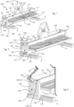
- FIG. 1 illustrates an embodiment of a tool for cutting a slate plate, or similar material, according to the invention.
- the tool 100 is positioned between two battens A in the use position.
- the guide rail is constituted by two L-shaped profiles 121 (also called “angle") arranged facing each other and at a distance from each other to provide a passage for a cutting carriage 130 mounted sliding along the guide rail 120.
- the cutting carriage 130 includes a gripping handle 131 fixed to a casing 132.
- the latter protects a cutting disc 133 engaged in the cutting slot 111 and rotatably mounted in the casing by a shaft 134.
- the casing includes bearings (not visible in the figure) arranged above and below the horizontal tracks 122 of the angles 121 of the guide rail.
- the cutting tool 100 also includes a chute 140 for collecting cutting waste.
- This chute 140 is arranged under the cutting table 110 in order to collect the cutting waste falling through the slot 111 of the cutting table 110.
- the chute 140 comprises a bottom 141, two side walls 142 and two end walls 143.
- Each end wall 143 is extended, below the level of the bottom 141 of the chute 140, by feet 148 which allow the tool to abut against one of the battens A of the roof.
- the feet 148 have teeth 149 directed towards the center of the tool so as to ensure better retention of the tool against the battens A by the simple weight of the tool 100 itself.
- At least one of the end walls 143 is pierced with a waste evacuation window 144.
- a hatch 150 is associated with the end wall 143 pierced by the window 144 and it is mounted movably between a collection position in which the hatch 150 closes the evacuation window 144, and an emptying position in which the hatch 150 clears the window to let the waste pass.
- the hatch 150 is slidably mounted parallel to the end wall 143 which carries it.
- the hatch 150 is arranged between the end wall 143 and the angles 121 so that it is held in sliding position by the horizontal tracks 122.
- the hatch 150 and the end wall 143 which carries it are each pierced with a security hole, respectively 151 and 145.
- These security holes 145 and 151 are arranged such that in the collection position , the security hole 145 of the end wall 143 and the security hole 151 of the hatch 150 face each other.
- the arrangement according to the invention therefore not only makes it possible to easily evacuate the waste by tilting the tool 100 when the hatch 150 is open while also providing a system for locking the hatch in the closed position, which is simple, economical and very effective.
- the safety member 160 illustrated in Figure 3 is a carabiner but it is also possible to choose a split ring, a shackle, a quick link, or any other device allowing it to be inserted securely into holes 145 and 151.
- the safety member is arranged at one end of a strap 161 for carrying the tool.
- each end wall of the chute 140 is provided with a hatch 150, a window 144, a hole 145 and a hole 151.
- a hatch 150 is provided at its two ends with a safety member carabiner type for blocking the hatches 150 on the end walls 143 in the collection position.
- the or each hatch 150 and the or each end wall 143 is/are each pierced with a skylight, respectively 152 and 146.
- the skylights 146-152 are arranged such that in position collection, the skylight 152 of a hatch 150 and the skylight 146 of the end wall 143 face each other and constitute a handling handle.
- This handle has a double function: on the one hand it allows the tool 100 to be grasped at each end with one hand to move it, and on the other hand it allows the hatch 150 to be grasped and to slide it upwards to that it releases the window 144 of the end wall 143 and that the user can empty the waste collection chute.
- the illustrated arrangement is particularly advantageous since it allows the chute to be emptied without having to completely turn the tool over and is simple and economical.
- the hatch 150 can be pivotally mounted on the end wall which carries it.
- safety holes will be provided on the pivoting hatch and on the end wall to ensure that the hatch is held against the wall by a carabiner 160 or any other safety device when carrying the tool with a strap 161.
Landscapes
- Engineering & Computer Science (AREA)
- Mechanical Engineering (AREA)
- Mining & Mineral Resources (AREA)
- Life Sciences & Earth Sciences (AREA)
- Forests & Forestry (AREA)
- Architecture (AREA)
- Civil Engineering (AREA)
- Structural Engineering (AREA)
- Emergency Lowering Means (AREA)
Description
L'invention concerne un outil de découpe d'ardoise ou de plaques en matériau analogue, en particulier transportable et utilisable sur un toit.The invention relates to a tool for cutting slate or plates of similar material, in particular transportable and usable on a roof.
Dans le domaine de la couverture d'habitation, plusieurs matériaux peuvent être utilisés : le zinc, la tuile ou la pierre, telle que de l'ardoise. D'autre matériaux synthétiques peuvent être utilisés pour imiter l'aspect des matières précédemment citées. Par exemple, on peut citer les plaques en fibrociment comme matériau analogue à l'ardoise.In the field of home roofing, several materials can be used: zinc, tiles or stone, such as slate. Other synthetic materials can be used to imitate the appearance of the previously mentioned materials. For example, we can cite fiber cement boards as a material similar to slate.
Dans le domaine de la couverture en ardoise, il existe de nombreux outils spécifiques à cette matière et destinés à couper les plaques, à les tailler selon une forme courbe choisie, à les percer et à les fixer.In the field of slate roofing, there are many tools specific to this material and intended for cutting the plates, cutting them into a chosen curved shape, drilling them and fixing them.
En général, le couvreur coupe au sol les plaques d'ardoises à la dimension générale voulue, puis les monte sur le toit à couvrir et les retaille plus finement à l'aide de pinces ou de marteaux spéciaux. Puis il les perce (opération aussi appelée « poinçonnage ») et les fixe par des crochets sur les liteaux du toit. Ces derniers sont des tasseaux longitudinaux, généralement en bois, fixés transversalement à la charpente (généralement les chevrons) du toit et perpendiculairement à la pente du toit.In general, the roofer cuts the slate sheets on the ground to the desired general size, then mounts them on the roof to be covered and recuts them more finely using pliers or special hammers. Then he drills them (an operation also called “punching”) and fixes them with hooks on the roof battens. The latter are longitudinal battens, generally made of wood, fixed transversely to the frame (generally the rafters) of the roof and perpendicular to the slope of the roof.
Une fois les ardoises posées, soit le couvreur se détache du système de sécurité antichute et redescend de la toiture pour préparer de nouvelles ardoises, soit il est aidé par un assistant qui peut lui monter de nouvelles ardoises pré taillées pour gagner du temps et lui éviter de se détacher. Dans ce dernier cas, les coûts de main d'oeuvre sont beaucoup plus importants.Once the slates have been installed, either the roofer detaches himself from the fall protection system and comes down from the roof to prepare new slates, or he is helped by an assistant who can install new pre-cut slates to save him time and to break away. In the latter case, labor costs are much higher.
L'un des outils de découpe d'ardoise ou de plaques en fibrociment les plus connus est le modèle CA600 de la société JOUANEL. Cet outil comporte un cadre délimitant une table de découpe portant une fente de découpe au-dessus de laquelle est agencé un rail de guidage. Un charriot muni d'un disque de découpe engagé dans la fente et d'une poignée de tirage est monté coulissant sur le rail. Une première extrémité du rail comporte un moyen de retenue réversible (généralement une vis à bille) du chariot et l'autre extrémité comporte un tampon d'amortissement de chocs en fin de course.One of the best-known slate or fiber cement board cutting tools is the CA600 model from the JOUANEL company. This tool comprises a frame delimiting a cutting table carrying a cutting slot above which a guide rail is arranged. A carriage fitted with a cutting disc engaged in the slot and a pulling handle is slidably mounted on the rail. A first end of the rail has a reversible retaining means (generally a ball screw) of the carriage and the other end has a shock absorbing pad at the end of the stroke.
L'outil comprend également une table d'appui préférablement munie de butées d'équerrage. La table d'appui est montée de manière coplanaire avec la table de découpe pour permettre l'appui d'une partie de la plaque pendant la découpe. Elle peut être fixée à droite ou à gauche de la table de découpe selon que l'opérateur est gaucher ou droitier.The tool also includes a support table preferably equipped with squareness stops. The support table is mounted coplanar with the cutting table to allow part of the plate to be supported during cutting. It can be fixed to the right or left of the cutting table depending on whether the operator is left-handed or right-handed.
Ce dernier place alors la plaque à découper sur la table de découpe et la table d'appui. Ensuite, il déverrouille le moyen de retenue puis il tire le charriot vers lui pour découper la plaque. Enfin, il replace le charriot à la première extrémité et le verrouille pour éviter qu'il ne glisse tout seul et blesse l'utilisateur.The latter then places the cutting plate on the cutting table and the support table. Then, he unlocks the retaining means and then pulls the carriage towards him to cut the plate. Finally, he returns the cart to the first end and locks it to prevent it from sliding on its own and injuring the user.
Cet outil est très lourd (plus de 22 kg) et n'est pas transportable sur le toit par une seule personne.This tool is very heavy (more than 22 kg) and cannot be transported on the roof by a single person.
Les déchets de coupe évacués par la fente tombent directement sur le sol qui doit être balayé par la suite.The cutting waste evacuated through the slot falls directly onto the ground which must then be swept up.
Pour être déplacé, l'outil comprend une poignée de préhension fixée sur le corps de l'outil dans un plan perpendiculaire au plan de découpe. Il comprend également un dispositif de blocage du chariot à une extrémité du rail pendant le transport pour éviter que ce dernier ne roule le long du guide et crée un déséquilibre dangereux en raison de son poids pendant que l'utilisateur tient la poignée dans une ou deux mains.To be moved, the tool includes a gripping handle fixed on the body of the tool in a plane perpendicular to the cutting plane. It also includes a carriage lock at one end of the rail during transport to prevent the carriage from rolling along the guide and creating a dangerous imbalance due to its weight while the user holds the handle in one or two hands.
Pour pallier ces problèmes, il a déjà été proposé un outil de conception similaire, beaucoup plus léger, et destiné à être monté et utilisé directement sur le toit, appelé « Mini Cad » de la société DIMOS.To overcome these problems, a tool of similar design, much lighter, and intended to be mounted and used directly on the roof, called “Mini Cad” from the company DIMOS, has already been proposed.
Cet outil comprend un cadre surélevé par des pieds dentés et une goulotte de collecte des déchets de coupe surmontée par la table de découpe portant la fente de découpe. La goulotte de collecte est nécessaire pour éviter que les déchets n'abîment le toit. L'outil comprend également un rail de guidage, un charriot de coupe, ainsi qu'une table d'appui à fixer à droite ou à gauche de la table de découpe selon que l'utilisateur est droitier ou gaucher.This tool includes a frame raised by toothed feet and a cutting waste collection chute surmounted by the cutting table carrying the cutting slot. The collection chute is necessary to prevent waste from damaging the roof. The tool also includes a guide rail, a cutting carriage, as well as a support table to be fixed to the right or left of the cutting table depending on whether the user is right-handed or left-handed.
L'écartement des pieds est choisi pour qu'ils puissent être insérés entre deux liteaux afin de maintenir l'outil sur le toit et éviter qu'il ne glisse. Une fois que la surface à proximité de l'utilisateur est couverte d'ardoises, ce dernier remonte légèrement l'outil pour dégager les dents du liteau et fait coulisser l'outil à proximité d'une nouvelle zone à couvrir.The spacing of the feet is chosen so that they can be inserted between two battens in order to hold the tool on the roof and prevent it from slipping. Once the surface near the user is covered with slates, the latter raises the tool slightly to release the teeth from the batten and slides the tool near a new area to be covered.
Si cet outil présente l'avantage de permettre une découpe des ardoises sur le toit, c'est-à-dire sur le lieu même d'utilisation des ardoises, il présente tout de même de nombreux inconvénients.If this tool has the advantage of allowing slates to be cut on the roof, that is to say on the very place where the slates are used, it still has many disadvantages.
La présence de la goulotte de collecte entre la table de découpe et les pieds rend l'outil très instable et ce dernier bascule systématiquement lorsque l'utilisateur s'appuie sur la table d'appui. Le basculement peut être limité si les dents des pieds mordent fortement dans le liteau, mais ce dernier s'en trouve alors détérioré.The presence of the collection chute between the cutting table and the feet makes the tool very unstable and the latter systematically tips over when the user leans on the support table. Tilting can be limited if the teeth of the feet bite strongly into the batten, but the latter is then damaged.
La goulotte de collecte comprend un fond monté pivotant verticalement, de sorte que pour vider la goulotte, il faut basculer l'outil sur le côté et ouvrir pivoter le fond. Il faut alors secouer l'outil ainsi ouvert pour retirer les déchets, mais compte tenu de sa taille et de son poids dans cette position, il est fréquent que l'utilisateur le laisse tomber. Par ailleurs, il est fréquent que le fond de la goulotte se détache pendant le transport, ce qui vide la goulotte à un endroit non souhaité et risque de blesser l'utilisateur.The collection chute includes a vertically pivoting mounted bottom, so to empty the chute, the tool must be tilted to the side and the bottom pivoted open. It is then necessary to shake the tool thus opened to remove the waste, but given its size and its weight in this position, it is common for the user to drop it. Furthermore, it is common for the bottom of the chute to become detached during transport, which empties the chute in an undesired location and risks injuring the user.
Pour pouvoir être transporté sur le toit, cet outil comporte d'une part une sangle de transport fixée au cadre et d'autre part un dispositif de blocage réversible du chariot à une première extrémité du rail pour éviter que ce dernier ne roule le long du guide pendant le déplacement. Grâce à la sangle, l'utilisateur peut utiliser ses deux mains pour monter sur le toit.To be able to be transported on the roof, this tool includes on the one hand a transport strap attached to the frame and on the other hand a device for reversible blocking of the carriage at a first end of the rail to prevent the latter from rolling along the guide during movement. Thanks to the strap, the user can use both hands to climb onto the roof.
Néanmoins, l'outil est en fort déséquilibre de fait de l'agencement de verrouillage et l'outil pèse fortement sur l'épaule de l'utilisateur pendant la montée sur le toit. Du fait de ce déséquilibre, l'outil ne peut pas non plus être hissé sur le toit avec une corde, au risque d'endommager l'outil et/ou la maison.However, the tool is very unbalanced due to the locking arrangement and the tool weighs heavily on the user's shoulder while climbing onto the roof. Due to this imbalance, the tool cannot be hoisted onto the roof with a rope, at the risk of damaging the tool and/or the house.
Un outil de découpe selon le préambule de la revendication 1 est connu du document
L'objectif de la présente invention est de proposer un outil de découpe d'ardoise utilisable sur un toit, léger, pratique, sûr et économique.The objective of the present invention is to provide a slate cutting tool usable on a roof, light, practical, safe and economical.
Par pratique on entend que l'outil doit pouvoir être manipulé facilement, sans nécessité un effort important.By practical we mean that the tool must be able to be handled easily, without requiring significant effort.
Par sûr, on entend que l'outil doit être stable (pas de basculement ou de déséquilibre), aussi bien en utilisation qu'en transport.By safe, we mean that the tool must be stable (no tipping or unbalance), both in use and in transport.
Selon l'invention, l'outil comporte un système de collecte et d'évacuation des déchets ne nécessitant pas le basculement de l'outil tout en étant verrouillable automatiquement et facilement pendant le transport.According to the invention, the tool comprises a waste collection and evacuation system which does not require tipping of the tool while being lockable automatically and easily during transport.
L'outil peut donc être facilement être utilisé sur un toit sans risque que les déchets de coupe n'endommagent le toit et sans risque que l'outil ne se vide de manière intempestive pendant le transport.The tool can therefore easily be used on a roof without the risk of cutting waste damaging the roof and without the risk of the tool emptying unintentionally during transport.
Ainsi, l'invention a pour objet un outil de découpe d'une plaque d'ardoise ou matériau similaire comprenant :
- une table de découpe portant une fente de découpe au-dessus de laquelle est agencé un rail de guidage,
- un chariot de découpe monté coulissant le long du rail de guidage et muni d'un disque de découpe engagé dans la fente et d'une poignée de préhension
- une goulotte de collecte des déchets de coupe agencée sous la table de découpe, la goulotte de collecte comprenant un fond, deux parois latérales et deux parois d'extrémité,
- a cutting table carrying a cutting slot above which a guide rail is arranged,
- a cutting carriage mounted sliding along the guide rail and provided with a cutting disc engaged in the slot and a gripping handle
- a cutting waste collection chute arranged under the cutting table, the collection chute comprising a bottom, two side walls and two end walls,
Selon l'invention, au moins une des parois d'extrémité de la goulotte est percée d'une fenêtre d'évacuation des déchets et comprend, en outre, une trappe montée mobile entre une position de collecte dans laquelle la trappe ferme la fenêtre d'évacuation et une position de vidage dans laquelle la trappe dégage la fenêtre.According to the invention, at least one of the end walls of the chute is pierced with a waste evacuation window and further comprises a hatch mounted movably between a collection position in which the hatch closes the window. evacuation and an emptying position in which the hatch clears the window.
Selon d'autres modes de réalisation :
- la trappe peut être montée coulissante parallèlement à la paroi d'extrémité qui la porte ;
- la trappe peut être montée pivotante sur la paroi d'extrémité qui la porte ;
- la trappe et la paroi d'extrémité qui la porte peuvent être percées chacune d'un trou de sécurité agencés de telle sorte qu'en position de collecte, le trou de sécurité de la trappe et le trou de sécurité de la paroi d'extrémité sont en regard l'un de l'autre ;
- l'outil de découpe peut comprendre, en outre, un organe de sécurité présentant une partie annulaire ouvrable réversiblement apte à passer dans les trous de sécurité de la trappe et de la paroi d'extrémité en position de collecte et à interdire un mouvement de la trappe par rapport à la paroi d'extrémité ;
- l'organe de sécurité présentant une partie annulaire ouvrable réversiblement peut être choisi parmi un anneau brisé, un mousqueton, une manille et un maillon rapide ;
- l'outil de découpe peut comprendre une sangle de portage munie à chaque extrémité d'un organe de sécurité destiné à être fixé dans les trous de sécurité de la ou des trappe(s) et de la ou des parois d'extrémité ; et/ou
- la ou chaque trappe et la ou chaque paroi d'extrémité peuvent être percées chacune d'une lucarne, les lucarnes étant agencées de telle sorte qu'en position de collecte, la lucarne d'une trappe et la lucarne de la paroi d'extrémité portant la trappe sont en regard l'une de l'autre pour constituer une poignée de manutention.
- the hatch can be mounted sliding parallel to the end wall which carries it;
- the hatch can be pivotally mounted on the end wall which carries it;
- the hatch and the end wall which carries it can each be pierced with a security hole arranged so that in the collection position, the security hole of the hatch and the security hole of the end wall are facing each other;
- the cutting tool may further comprise a safety member having a reversibly openable annular part capable of passing through the safety holes of the hatch and of the end wall in the collection position and of preventing movement of the hatch relative to the end wall;
- the safety member having a reversibly openable annular part can be chosen from a split ring, a carabiner, a shackle and a quick link;
- the cutting tool may comprise a carrying strap provided at each end with a safety member intended to be fixed in the safety holes of the hatch(es) and the end wall(s); and or
- the or each hatch and the or each end wall can each be pierced with a skylight, the skylights being arranged such that in the collection position, the skylight of a hatch and the skylight of the end wall carrying the hatch are facing each other to constitute a handling handle.
D'autres caractéristiques de l'invention seront énoncées dans la description détaillée ci-après, faite en référence aux dessins annexés, qui représentent, respectivement :
- la
figure 1 , une vue schématique en perspective d'un mode de réalisation préféré d'un outil de découpe selon l'invention dans lequel la trappe du collecteur de déchet est fermée, en position fermée de collecte des déchets ; - la
figure 2 , une vue schématique en perspective du mode de réalisation de lafigure 1 dans lequel la trappe du collecteur de déchet est en position ouverte de vidage des déchets ; et - la
figure 3 , une vue schématique en perspective d'un agrandissement partiel de lafigure 1 au niveau d'une extrémité de l'outil comprenant un organe de sécurité verrouillant la trappe en position fermée.
- there
figure 1 , a schematic perspective view of a preferred embodiment of a cutting tool according to the invention in which the hatch of the waste collector is closed, in the closed waste collection position; - there
figure 2 , a schematic perspective view of the embodiment of thefigure 1 in which the waste collector hatch is in the open waste emptying position; And - there
Figure 3 , a schematic perspective view of a partial enlargement of thefigure 1 at one end of the tool comprising a safety member locking the hatch in the closed position.
La
Il comprend une table de découpe 110 portant une fente 111 au-dessus de laquelle est agencé un rail de guidage 120. Dans ce mode de réalisation, le rail de guidage est constitué par deux profilés en L 121 (également appelés « cornière ») agencés en regard l'un de l'autre et à distance l'un de l'autre pour ménager un passage pour un chariot de découpe 130 monté coulissant le long du rail de guidage 120.It comprises a cutting table 110 carrying a
Le chariot de découpe 130 comprend une poignée de préhension 131 fixée à un carter 132. Ce dernier protège un disque de découpe 133 engagé dans la fente de découpe 11 1 et monté rotatif dans le carter par un arbre 134.The cutting
Le carter comporte des roulements (non visible sur la figure) agencés au-dessus et en dessous des pistes horizontales 122 des cornières 121 du rail de guidage.The casing includes bearings (not visible in the figure) arranged above and below the
L'outil de découpe 100 selon l'invention comporte également une goulotte 140 de collecte des déchets de coupe. Cette goulotte 140 est agencée sous la table de coupe 110 afin de recueillir les déchets de coupe tombant par la fente 111 de la table de coupe 110.The
La goulotte 140 comprend un fond 141, deux parois latérales 142 et deux parois d'extrémité 143.The
Chaque paroi d'extrémité 143 est prolongée, sous le niveau du fond 141 de la goulotte 140 par des pieds 148 qui permettent à l'outil d'être en butée contre un des liteaux A du toit. De préférence, les pieds 148 présentent des dents 149 dirigées vers le centre de l'outil de manière à assurer une meilleure retenue de l'outil contre les liteaux A par le simple poids de l'outil 100 lui-même.Each
Selon l'invention, au moins une des parois d'extrémité 143 est percée d'une fenêtre d'évacuation des déchets 144. Une trappe 150 est associée à la paroi d'extrémité 143 percée par la fenêtre 144 et elle est montée mobile entre une position de collecte dans laquelle la trappe 150 ferme la fenêtre d'évacuation 144, et une position de vidage dans laquelle la trappe 150 dégage la fenêtre pour laisser passer les déchets.According to the invention, at least one of the
Dans le mode de réalisation illustrée, la trappe 150 est montée coulissante parallèlement à la paroi d'extrémité 143 qui la porte. De préférence, la trappe 150 est agencée entre la paroi d'extrémité 143 et les cornières 121 de telle sorte qu'elle est maintenue en position coulissante par les pistes horizontales 122.In the illustrated embodiment, the
De manière avantageuse, la trappe 150 et la paroi d'extrémité 143 qui la porte sont percées chacune d'un trou de sécurité, respectivement 151 et 145. Ces trous de sécurité 145 et 151 sont agencés de telle sorte qu'en position de collecte, le trou de sécurité 145 de la paroi d'extrémité 143 et le trou de sécurité 151 de la trappe 150 sont en regard l'un de l'autre.Advantageously, the
Cet agencement permet d'enfiler dans ces deux trous 145 - 151 en regard l'un de l'autre une partie annulaires ouvrable réversiblement d'un organe de sécurité 160 (voir
L'agencement selon l'invention permet donc non seulement d'évacuer facilement les déchets en basculant l'outil 100 lorsque la trappe 150 est ouverte tout en proposant un système de verrouillage de la trappe en position fermée, simple, économique et très efficace.The arrangement according to the invention therefore not only makes it possible to easily evacuate the waste by tilting the
L'organe de sécurité 160 illustré en
De préférence, l'organe de sécurité est agencé à une extrémité d'une sangle 161 de portage de l'outil.Preferably, the safety member is arranged at one end of a
Pour assurer une grande polyvalence de l'outil, chaque paroi d'extrémité de la goulotte 140 est munie d'une trappe 150, d'une fenêtre 144, d'un trou 145 et d'un trou 151. De cette manière, il est possible d'évacuer les déchets quel que soit le positionnement de l'outil 100 et il est également possible d'utiliser une sangle 161 munie à ses deux extrémités d'un organe de sécurité de type mousqueton pour bloquer les trappes 150 sur les parois d'extrémité 143 en position de collecte.To ensure great versatility of the tool, each end wall of the
Dans un mode de réalisation avantageuse, la ou chaque trappe 150 et la ou chaque paroi d'extrémité 143 est/sont percées chacune d'une lucarne, respectivement 152 et 146. Les lucarnes 146-152 sont agencées de telle sorte qu'en position de collecte, la lucarne 152 d'une trappe 150 et la lucarne 146 de la paroi d'extrémité 143 sont en regard l'une de l'autre et constituent une poignée de manutention.In an advantageous embodiment, the or each
Cette poignée a une double fonction : d'une part elle permet de saisir l'outil 100 à chaque extrémité avec une main pour le déplacer, et d'autre part elle permet de saisir la trappe 150 et de la faire coulisser vers le haut pour qu'elle libère la fenêtre 144 de la paroi d'extrémité 143 et que l'utilisateur puisse vider la goulotte de collecte des déchets.This handle has a double function: on the one hand it allows the
L'agencement illustré est particulièrement avantageux puisqu'il permet de vider la goulotte sans avoir à retourner totalement l'outil et qu'il est simple et économique.The illustrated arrangement is particularly advantageous since it allows the chute to be emptied without having to completely turn the tool over and is simple and economical.
Dans un mode de réalisation non illustrée, la trappe 150 peut être montée de manière pivotante sur la paroi d'extrémité qui la porte. Dans ce cas, on prévoira des trous de sécurité sur la trappe pivotante et sur la paroi d'extrémité pour assurer le maintien de la trappe contre la paroi par un mousqueton 160 ou tout autre organe de sécurité lors du portage de l'outil avec une sangle 161.In an embodiment not illustrated, the
Claims (8)
- Cutting tool (100) for cutting a sheet of slate or similar material, comprising:• a cutting table (110) which has a cutting slot (111) over which a guide rail (120) is arranged,• a cutting carriage (130) mounted so that it can slide along the guide rail, and fitted with a cutting disc (133) engaged in the slot, and with a grab handle (131),• a channel (140) for collecting the cutting waste, which channel is arranged under the cutting table (110), the collecting channel comprising a bottom (141), two lateral walls (142) and two end walls (143),characterized in that at least one of the end walls (143) of the channel is pierced with a waste removal window (144) and further comprises a hatch (150) mounted with the ability to move between a collection position in which the hatch (150) closes the removal window (144) and an emptying position in which the hatch (150) uncovers the removal window (144).
- Cutting tool according to Claim 1, in which the hatch (150) is mounted with the ability to slide parallel to the end wall (143) that bears it.
- Cutting tool according to Claim 1, in which the hatch (150) is mounted with the ability to pivot on the end wall that bears it.
- Cutting tool according to any one of Claims 1 to 3, in which the hatch (150) and the end wall (143) that bears it are each pierced with a safety hole (145-151) which holes are arranged in such a way that, in the collection position, the safety hole (151) of the hatch (150) and the safety hole (145) of the end wall (143) face one another.
- Cutting tool according to Claim 4, further comprising a safety member (160) having a reversibly openable annular part able to enter the safety holes (145-151) in the hatch (150) and in the end wall (143) in the collecting position and to prevent movement of the hatch with respect to the end wall.
- Cutting tool according to Claim 5, in which the safety member (160) having a reversibly openable annular part is chosen from a split ring, a carabiner, a shackle and a quick link.
- Cutting tool according to Claim 5 or 6, comprising a carry strap (161) equipped at each end with a safety member (160) intended to be fixed into the safety holes (145-151) of the hatch(es) and of the end wall(s).
- Cutting tool according to any one of Claims 1 to 7, in which the or each hatch (150) and the or each end wall (143) are each pierced with a cutout (146-152), the cutouts being arranged in such a way that, in the collection position, the cutout (152) of a hatch (150) and the cutout (146) of the end wall (143) bearing the hatch (150) face one another to constitute a handling handle.
Priority Applications (1)
| Application Number | Priority Date | Filing Date | Title |
|---|---|---|---|
| EP18208741.1A EP3659770B1 (en) | 2018-11-28 | 2018-11-28 | Tool for cutting slate plates with waste collector |
Applications Claiming Priority (1)
| Application Number | Priority Date | Filing Date | Title |
|---|---|---|---|
| EP18208741.1A EP3659770B1 (en) | 2018-11-28 | 2018-11-28 | Tool for cutting slate plates with waste collector |
Publications (2)
| Publication Number | Publication Date |
|---|---|
| EP3659770A1 EP3659770A1 (en) | 2020-06-03 |
| EP3659770B1 true EP3659770B1 (en) | 2023-10-11 |
Family
ID=64556688
Family Applications (1)
| Application Number | Title | Priority Date | Filing Date |
|---|---|---|---|
| EP18208741.1A Active EP3659770B1 (en) | 2018-11-28 | 2018-11-28 | Tool for cutting slate plates with waste collector |
Country Status (1)
| Country | Link |
|---|---|
| EP (1) | EP3659770B1 (en) |
Families Citing this family (2)
| Publication number | Priority date | Publication date | Assignee | Title |
|---|---|---|---|---|
| CN115847630A (en) * | 2023-01-03 | 2023-03-28 | 山东莘州新型建材科技有限公司 | Autoclaved aerated concrete slab cutting processing equipment and processing method thereof |
| CN118254291A (en) * | 2024-05-07 | 2024-06-28 | 深圳市睿诚建材有限公司 | Building decorative panel processingequipment |
Citations (1)
| Publication number | Priority date | Publication date | Assignee | Title |
|---|---|---|---|---|
| FR2861630B1 (en) * | 2003-10-29 | 2007-01-19 | Participations G | APPARATUS FOR THE SLICING OF PLATE MATERIALS AND ASSOCIATED COLLECTION DEVICE |
Family Cites Families (4)
| Publication number | Priority date | Publication date | Assignee | Title |
|---|---|---|---|---|
| DE29917589U1 (en) * | 1999-10-06 | 2000-01-20 | Schretzmann, Gabriele, 53902 Bad Münstereifel | Slate bucket |
| JP2001205624A (en) * | 2000-01-28 | 2001-07-31 | Ota Kosan:Kk | Cutter device |
| FR2917000B1 (en) * | 2007-06-11 | 2009-08-28 | Paul Parisse | CIRCULAR SAW WITH RECOVERY OF SAW |
| CN108274554A (en) * | 2018-03-26 | 2018-07-13 | 佛山市博蓄科技有限公司 | A kind of regulating multi-functional cutting machine |
-
2018
- 2018-11-28 EP EP18208741.1A patent/EP3659770B1/en active Active
Patent Citations (1)
| Publication number | Priority date | Publication date | Assignee | Title |
|---|---|---|---|---|
| FR2861630B1 (en) * | 2003-10-29 | 2007-01-19 | Participations G | APPARATUS FOR THE SLICING OF PLATE MATERIALS AND ASSOCIATED COLLECTION DEVICE |
Also Published As
| Publication number | Publication date |
|---|---|
| EP3659770A1 (en) | 2020-06-03 |
Similar Documents
| Publication | Publication Date | Title |
|---|---|---|
| EP3659770B1 (en) | Tool for cutting slate plates with waste collector | |
| EP3659772B1 (en) | Stabilised tool for cutting slates | |
| FR2867716A1 (en) | FOLDING KNIFE WITH BLADE LOCKING MEANS | |
| WO2001052938A2 (en) | Fall-prevention device | |
| CA2966959A1 (en) | Lifting mechanism for an apparatus for lifting construction plates, lifting apparatus comprising this mechanism, and lifting method using this apparatus | |
| FR3072317B1 (en) | TOOL FOR CUTTING SLATE PLATES TO A COLLECTOR OF WASTE | |
| FR3072318B1 (en) | STABILIZED SLATE CUTTING TOOL | |
| EP3659771A1 (en) | Portable tool for cutting slates | |
| US6176469B1 (en) | Manhole cover engaging tools | |
| US6981346B1 (en) | Ice fishing hole strainer device | |
| EP2003274B1 (en) | Device for securing a secure access of an emergency access to a public infrastructure | |
| FR2899253A1 (en) | Technical chamber e.g. manhole, access device, has anchoring post articulated on base for varying between folded and raised positions, where base has arches automatically actuated by manipulation of post toward raised position | |
| EP1253280B1 (en) | Device for a safety anchor | |
| FR2970725A1 (en) | Device for handling plaster plate, has frame provided with gripping handle located between connection areas connecting hooks to frame, and adjustment unit for adjusting position of handle on frame along part of separating distance | |
| EP3215691B1 (en) | Mechanism for fastening in a swivelling manner a plate carrier to a telescopic mast of a plate-lifting apparatus, and plate-lifting apparatus equipped with this mechanism | |
| FR2861630A1 (en) | Working material slicing apparatus for use in building site, has waste material collecting and storing unit to collect and store waste materials that are produced as result of slicing of materials on slab, by gravity of fall | |
| FR2540030A1 (en) | Circular saw with tilting trestle | |
| EP0402214A1 (en) | Safety device for the access to a ladder from an upper floor | |
| FR2635817A1 (en) | Simple and portable ladder, step-ladder and accommodation ladder device with horizontal steps in all positions | |
| FR2865998A1 (en) | Ladder for aircraft, has visual alert device that is visible when safety device is actuated to close upper door`s opening, so that persons located at upper level are informed that door is open and that ladder is in maintenance position | |
| CN208306679U (en) | A kind of gas bottle trolley | |
| CH711489A1 (en) | A blade sleeve for a hand cutting tool, an associated cutting tool and an assembly comprising such a sleeve and such a cutting tool. | |
| EP0014811A1 (en) | Removable device for fixation on a roof | |
| CA2543636A1 (en) | Maneuvering device for controlled tilting of a cut up trunk portion | |
| EP4360716A1 (en) | Mobile fall protection device |
Legal Events
| Date | Code | Title | Description |
|---|---|---|---|
| PUAI | Public reference made under article 153(3) epc to a published international application that has entered the european phase |
Free format text: ORIGINAL CODE: 0009012 |
|
| STAA | Information on the status of an ep patent application or granted ep patent |
Free format text: STATUS: THE APPLICATION HAS BEEN PUBLISHED |
|
| AK | Designated contracting states |
Kind code of ref document: A1 Designated state(s): AL AT BE BG CH CY CZ DE DK EE ES FI FR GB GR HR HU IE IS IT LI LT LU LV MC MK MT NL NO PL PT RO RS SE SI SK SM TR |
|
| AX | Request for extension of the european patent |
Extension state: BA ME |
|
| STAA | Information on the status of an ep patent application or granted ep patent |
Free format text: STATUS: REQUEST FOR EXAMINATION WAS MADE |
|
| 17P | Request for examination filed |
Effective date: 20210322 |
|
| RBV | Designated contracting states (corrected) |
Designated state(s): AL AT BE BG CH CY CZ DE DK EE ES FI FR GB GR HR HU IE IS IT LI LT LU LV MC MK MT NL NO PL PT RO RS SE SI SK SM TR |
|
| GRAP | Despatch of communication of intention to grant a patent |
Free format text: ORIGINAL CODE: EPIDOSNIGR1 |
|
| STAA | Information on the status of an ep patent application or granted ep patent |
Free format text: STATUS: GRANT OF PATENT IS INTENDED |
|
| INTG | Intention to grant announced |
Effective date: 20230412 |
|
| RBV | Designated contracting states (corrected) |
Designated state(s): AL AT BE BG CH CY CZ DE DK EE ES FI GB GR HR HU IE IS IT LI LT LU LV MC MK MT NL NO PL PT RO RS SE SI SK SM TR |
|
| P01 | Opt-out of the competence of the unified patent court (upc) registered |
Effective date: 20230509 |
|
| GRAS | Grant fee paid |
Free format text: ORIGINAL CODE: EPIDOSNIGR3 |
|
| GRAA | (expected) grant |
Free format text: ORIGINAL CODE: 0009210 |
|
| STAA | Information on the status of an ep patent application or granted ep patent |
Free format text: STATUS: THE PATENT HAS BEEN GRANTED |
|
| AK | Designated contracting states |
Kind code of ref document: B1 Designated state(s): AL AT BE BG CH CY CZ DE DK EE ES FI GB GR HR HU IE IS IT LI LT LU LV MC MK MT NL NO PL PT RO RS SE SI SK SM TR |
|
| RAP1 | Party data changed (applicant data changed or rights of an application transferred) |
Owner name: EDMA |
|
| REG | Reference to a national code |
Ref country code: GB Ref legal event code: FG4D Free format text: NOT ENGLISH |
|
| REG | Reference to a national code |
Ref country code: CH Ref legal event code: EP |
|
| REG | Reference to a national code |
Ref country code: DE Ref legal event code: R096 Ref document number: 602018059076 Country of ref document: DE |
|
| REG | Reference to a national code |
Ref country code: IE Ref legal event code: FG4D Free format text: LANGUAGE OF EP DOCUMENT: FRENCH |
|
| PGFP | Annual fee paid to national office [announced via postgrant information from national office to epo] |
Ref country code: GB Payment date: 20231121 Year of fee payment: 6 |
|
| PGFP | Annual fee paid to national office [announced via postgrant information from national office to epo] |
Ref country code: DE Payment date: 20231019 Year of fee payment: 6 |
|
| REG | Reference to a national code |
Ref country code: LT Ref legal event code: MG9D |
|
| REG | Reference to a national code |
Ref country code: NL Ref legal event code: MP Effective date: 20231011 |
|
| PGFP | Annual fee paid to national office [announced via postgrant information from national office to epo] |
Ref country code: BE Payment date: 20231121 Year of fee payment: 6 |
|
| REG | Reference to a national code |
Ref country code: AT Ref legal event code: MK05 Ref document number: 1619766 Country of ref document: AT Kind code of ref document: T Effective date: 20231011 |
|
| PG25 | Lapsed in a contracting state [announced via postgrant information from national office to epo] |
Ref country code: NL Free format text: LAPSE BECAUSE OF FAILURE TO SUBMIT A TRANSLATION OF THE DESCRIPTION OR TO PAY THE FEE WITHIN THE PRESCRIBED TIME-LIMIT Effective date: 20231011 |
|
| PG25 | Lapsed in a contracting state [announced via postgrant information from national office to epo] |
Ref country code: GR Free format text: LAPSE BECAUSE OF FAILURE TO SUBMIT A TRANSLATION OF THE DESCRIPTION OR TO PAY THE FEE WITHIN THE PRESCRIBED TIME-LIMIT Effective date: 20240112 |
|
| PG25 | Lapsed in a contracting state [announced via postgrant information from national office to epo] |
Ref country code: IS Free format text: LAPSE BECAUSE OF FAILURE TO SUBMIT A TRANSLATION OF THE DESCRIPTION OR TO PAY THE FEE WITHIN THE PRESCRIBED TIME-LIMIT Effective date: 20240211 |
|
| PG25 | Lapsed in a contracting state [announced via postgrant information from national office to epo] |
Ref country code: LT Free format text: LAPSE BECAUSE OF FAILURE TO SUBMIT A TRANSLATION OF THE DESCRIPTION OR TO PAY THE FEE WITHIN THE PRESCRIBED TIME-LIMIT Effective date: 20231011 |
|
| PG25 | Lapsed in a contracting state [announced via postgrant information from national office to epo] |
Ref country code: AT Free format text: LAPSE BECAUSE OF FAILURE TO SUBMIT A TRANSLATION OF THE DESCRIPTION OR TO PAY THE FEE WITHIN THE PRESCRIBED TIME-LIMIT Effective date: 20231011 |
|
| PG25 | Lapsed in a contracting state [announced via postgrant information from national office to epo] |
Ref country code: ES Free format text: LAPSE BECAUSE OF FAILURE TO SUBMIT A TRANSLATION OF THE DESCRIPTION OR TO PAY THE FEE WITHIN THE PRESCRIBED TIME-LIMIT Effective date: 20231011 |
|
| PG25 | Lapsed in a contracting state [announced via postgrant information from national office to epo] |
Ref country code: LT Free format text: LAPSE BECAUSE OF FAILURE TO SUBMIT A TRANSLATION OF THE DESCRIPTION OR TO PAY THE FEE WITHIN THE PRESCRIBED TIME-LIMIT Effective date: 20231011 Ref country code: IS Free format text: LAPSE BECAUSE OF FAILURE TO SUBMIT A TRANSLATION OF THE DESCRIPTION OR TO PAY THE FEE WITHIN THE PRESCRIBED TIME-LIMIT Effective date: 20240211 Ref country code: GR Free format text: LAPSE BECAUSE OF FAILURE TO SUBMIT A TRANSLATION OF THE DESCRIPTION OR TO PAY THE FEE WITHIN THE PRESCRIBED TIME-LIMIT Effective date: 20240112 Ref country code: ES Free format text: LAPSE BECAUSE OF FAILURE TO SUBMIT A TRANSLATION OF THE DESCRIPTION OR TO PAY THE FEE WITHIN THE PRESCRIBED TIME-LIMIT Effective date: 20231011 Ref country code: BG Free format text: LAPSE BECAUSE OF FAILURE TO SUBMIT A TRANSLATION OF THE DESCRIPTION OR TO PAY THE FEE WITHIN THE PRESCRIBED TIME-LIMIT Effective date: 20240111 Ref country code: AT Free format text: LAPSE BECAUSE OF FAILURE TO SUBMIT A TRANSLATION OF THE DESCRIPTION OR TO PAY THE FEE WITHIN THE PRESCRIBED TIME-LIMIT Effective date: 20231011 Ref country code: PT Free format text: LAPSE BECAUSE OF FAILURE TO SUBMIT A TRANSLATION OF THE DESCRIPTION OR TO PAY THE FEE WITHIN THE PRESCRIBED TIME-LIMIT Effective date: 20240212 |
|
| PG25 | Lapsed in a contracting state [announced via postgrant information from national office to epo] |
Ref country code: SE Free format text: LAPSE BECAUSE OF FAILURE TO SUBMIT A TRANSLATION OF THE DESCRIPTION OR TO PAY THE FEE WITHIN THE PRESCRIBED TIME-LIMIT Effective date: 20231011 Ref country code: RS Free format text: LAPSE BECAUSE OF FAILURE TO SUBMIT A TRANSLATION OF THE DESCRIPTION OR TO PAY THE FEE WITHIN THE PRESCRIBED TIME-LIMIT Effective date: 20231011 Ref country code: PL Free format text: LAPSE BECAUSE OF FAILURE TO SUBMIT A TRANSLATION OF THE DESCRIPTION OR TO PAY THE FEE WITHIN THE PRESCRIBED TIME-LIMIT Effective date: 20231011 Ref country code: NO Free format text: LAPSE BECAUSE OF FAILURE TO SUBMIT A TRANSLATION OF THE DESCRIPTION OR TO PAY THE FEE WITHIN THE PRESCRIBED TIME-LIMIT Effective date: 20240111 Ref country code: LV Free format text: LAPSE BECAUSE OF FAILURE TO SUBMIT A TRANSLATION OF THE DESCRIPTION OR TO PAY THE FEE WITHIN THE PRESCRIBED TIME-LIMIT Effective date: 20231011 Ref country code: HR Free format text: LAPSE BECAUSE OF FAILURE TO SUBMIT A TRANSLATION OF THE DESCRIPTION OR TO PAY THE FEE WITHIN THE PRESCRIBED TIME-LIMIT Effective date: 20231011 |
|
| REG | Reference to a national code |
Ref country code: CH Ref legal event code: PL |
|
| PG25 | Lapsed in a contracting state [announced via postgrant information from national office to epo] |
Ref country code: DK Free format text: LAPSE BECAUSE OF FAILURE TO SUBMIT A TRANSLATION OF THE DESCRIPTION OR TO PAY THE FEE WITHIN THE PRESCRIBED TIME-LIMIT Effective date: 20231011 |
|
| REG | Reference to a national code |
Ref country code: DE Ref legal event code: R097 Ref document number: 602018059076 Country of ref document: DE |
|
| PG25 | Lapsed in a contracting state [announced via postgrant information from national office to epo] |
Ref country code: LU Free format text: LAPSE BECAUSE OF NON-PAYMENT OF DUE FEES Effective date: 20231128 |
|
| PG25 | Lapsed in a contracting state [announced via postgrant information from national office to epo] |
Ref country code: CH Free format text: LAPSE BECAUSE OF NON-PAYMENT OF DUE FEES Effective date: 20231130 |
|
| PG25 | Lapsed in a contracting state [announced via postgrant information from national office to epo] |
Ref country code: CZ Free format text: LAPSE BECAUSE OF FAILURE TO SUBMIT A TRANSLATION OF THE DESCRIPTION OR TO PAY THE FEE WITHIN THE PRESCRIBED TIME-LIMIT Effective date: 20231011 |
|
| PG25 | Lapsed in a contracting state [announced via postgrant information from national office to epo] |
Ref country code: SK Free format text: LAPSE BECAUSE OF FAILURE TO SUBMIT A TRANSLATION OF THE DESCRIPTION OR TO PAY THE FEE WITHIN THE PRESCRIBED TIME-LIMIT Effective date: 20231011 |
|
| PG25 | Lapsed in a contracting state [announced via postgrant information from national office to epo] |
Ref country code: SM Free format text: LAPSE BECAUSE OF FAILURE TO SUBMIT A TRANSLATION OF THE DESCRIPTION OR TO PAY THE FEE WITHIN THE PRESCRIBED TIME-LIMIT Effective date: 20231011 Ref country code: SK Free format text: LAPSE BECAUSE OF FAILURE TO SUBMIT A TRANSLATION OF THE DESCRIPTION OR TO PAY THE FEE WITHIN THE PRESCRIBED TIME-LIMIT Effective date: 20231011 Ref country code: RO Free format text: LAPSE BECAUSE OF FAILURE TO SUBMIT A TRANSLATION OF THE DESCRIPTION OR TO PAY THE FEE WITHIN THE PRESCRIBED TIME-LIMIT Effective date: 20231011 Ref country code: LU Free format text: LAPSE BECAUSE OF NON-PAYMENT OF DUE FEES Effective date: 20231128 Ref country code: IT Free format text: LAPSE BECAUSE OF FAILURE TO SUBMIT A TRANSLATION OF THE DESCRIPTION OR TO PAY THE FEE WITHIN THE PRESCRIBED TIME-LIMIT Effective date: 20231011 Ref country code: EE Free format text: LAPSE BECAUSE OF FAILURE TO SUBMIT A TRANSLATION OF THE DESCRIPTION OR TO PAY THE FEE WITHIN THE PRESCRIBED TIME-LIMIT Effective date: 20231011 Ref country code: DK Free format text: LAPSE BECAUSE OF FAILURE TO SUBMIT A TRANSLATION OF THE DESCRIPTION OR TO PAY THE FEE WITHIN THE PRESCRIBED TIME-LIMIT Effective date: 20231011 Ref country code: CZ Free format text: LAPSE BECAUSE OF FAILURE TO SUBMIT A TRANSLATION OF THE DESCRIPTION OR TO PAY THE FEE WITHIN THE PRESCRIBED TIME-LIMIT Effective date: 20231011 Ref country code: CH Free format text: LAPSE BECAUSE OF NON-PAYMENT OF DUE FEES Effective date: 20231130 |
|
| PLBE | No opposition filed within time limit |
Free format text: ORIGINAL CODE: 0009261 |
|
| STAA | Information on the status of an ep patent application or granted ep patent |
Free format text: STATUS: NO OPPOSITION FILED WITHIN TIME LIMIT |
|
| PG25 | Lapsed in a contracting state [announced via postgrant information from national office to epo] |
Ref country code: MC Free format text: LAPSE BECAUSE OF FAILURE TO SUBMIT A TRANSLATION OF THE DESCRIPTION OR TO PAY THE FEE WITHIN THE PRESCRIBED TIME-LIMIT Effective date: 20231011 |
|
| PG25 | Lapsed in a contracting state [announced via postgrant information from national office to epo] |
Ref country code: MC Free format text: LAPSE BECAUSE OF FAILURE TO SUBMIT A TRANSLATION OF THE DESCRIPTION OR TO PAY THE FEE WITHIN THE PRESCRIBED TIME-LIMIT Effective date: 20231011 |
|
| REG | Reference to a national code |
Ref country code: IE Ref legal event code: MM4A |
|
| 26N | No opposition filed |
Effective date: 20240712 |