EP3659763A1 - Replacement of rotatable cutting discs of a power tool - Google Patents
Replacement of rotatable cutting discs of a power tool Download PDFInfo
- Publication number
- EP3659763A1 EP3659763A1 EP18208929.2A EP18208929A EP3659763A1 EP 3659763 A1 EP3659763 A1 EP 3659763A1 EP 18208929 A EP18208929 A EP 18208929A EP 3659763 A1 EP3659763 A1 EP 3659763A1
- Authority
- EP
- European Patent Office
- Prior art keywords
- shroud member
- shroud
- feature
- power tool
- parts
- Prior art date
- Legal status (The legal status is an assumption and is not a legal conclusion. Google has not performed a legal analysis and makes no representation as to the accuracy of the status listed.)
- Granted
Links
Images


Classifications
-
- B—PERFORMING OPERATIONS; TRANSPORTING
- B28—WORKING CEMENT, CLAY, OR STONE
- B28D—WORKING STONE OR STONE-LIKE MATERIALS
- B28D7/00—Accessories specially adapted for use with machines or devices of the preceding groups
- B28D7/02—Accessories specially adapted for use with machines or devices of the preceding groups for removing or laying dust, e.g. by spraying liquids; for cooling work
-
- B—PERFORMING OPERATIONS; TRANSPORTING
- B23—MACHINE TOOLS; METAL-WORKING NOT OTHERWISE PROVIDED FOR
- B23D—PLANING; SLOTTING; SHEARING; BROACHING; SAWING; FILING; SCRAPING; LIKE OPERATIONS FOR WORKING METAL BY REMOVING MATERIAL, NOT OTHERWISE PROVIDED FOR
- B23D59/00—Accessories specially designed for sawing machines or sawing devices
- B23D59/006—Accessories specially designed for sawing machines or sawing devices for removing or collecting chips
-
- B—PERFORMING OPERATIONS; TRANSPORTING
- B23—MACHINE TOOLS; METAL-WORKING NOT OTHERWISE PROVIDED FOR
- B23D—PLANING; SLOTTING; SHEARING; BROACHING; SAWING; FILING; SCRAPING; LIKE OPERATIONS FOR WORKING METAL BY REMOVING MATERIAL, NOT OTHERWISE PROVIDED FOR
- B23D45/00—Sawing machines or sawing devices with circular saw blades or with friction saw discs
- B23D45/16—Hand-held sawing devices with circular saw blades
-
- B—PERFORMING OPERATIONS; TRANSPORTING
- B23—MACHINE TOOLS; METAL-WORKING NOT OTHERWISE PROVIDED FOR
- B23Q—DETAILS, COMPONENTS, OR ACCESSORIES FOR MACHINE TOOLS, e.g. ARRANGEMENTS FOR COPYING OR CONTROLLING; MACHINE TOOLS IN GENERAL CHARACTERISED BY THE CONSTRUCTION OF PARTICULAR DETAILS OR COMPONENTS; COMBINATIONS OR ASSOCIATIONS OF METAL-WORKING MACHINES, NOT DIRECTED TO A PARTICULAR RESULT
- B23Q11/00—Accessories fitted to machine tools for keeping tools or parts of the machine in good working condition or for cooling work; Safety devices specially combined with or arranged in, or specially adapted for use in connection with, machine tools
- B23Q11/0042—Devices for removing chips
- B23Q11/0046—Devices for removing chips by sucking
-
- B—PERFORMING OPERATIONS; TRANSPORTING
- B23—MACHINE TOOLS; METAL-WORKING NOT OTHERWISE PROVIDED FOR
- B23Q—DETAILS, COMPONENTS, OR ACCESSORIES FOR MACHINE TOOLS, e.g. ARRANGEMENTS FOR COPYING OR CONTROLLING; MACHINE TOOLS IN GENERAL CHARACTERISED BY THE CONSTRUCTION OF PARTICULAR DETAILS OR COMPONENTS; COMBINATIONS OR ASSOCIATIONS OF METAL-WORKING MACHINES, NOT DIRECTED TO A PARTICULAR RESULT
- B23Q11/00—Accessories fitted to machine tools for keeping tools or parts of the machine in good working condition or for cooling work; Safety devices specially combined with or arranged in, or specially adapted for use in connection with, machine tools
- B23Q11/0042—Devices for removing chips
- B23Q11/0071—Devices for removing chips dust collectors for hand tools
Definitions
- This specification concerns facilitating a user to replace rotatable cutting discs of a power tool, for example a wall chaser.
- European patent number EP2552660B1 describes a wall chaser, which is a power tool for forming channels in a concrete surface. Objects such as cables and wires can be fed through such channels during a construction project. Wall chasers are known to carry a pair of axially offset cutting discs which in use form two parallel slots in a concrete surface. Subsequently a construction worker is required to chisel away the concrete remaining between such slots, thereby leaving a channel of the kind heretofore mentioned. It will be appreciated that the cutting discs are subject to wear and need replacing from time-to-time.
- Wall chaser products are known in which users must partially disassemble their wall chaser product, in other words physically separate respective parts thereof, to enable user access to the cutting discs for replacement or for other reasons e.g. to change the distance between cutting discs and thus cutting width. Furthermore, some wall chaser products require surprisingly high levels of dexterity to access the cutting discs thereof and can be difficult to open up in order to provide user access to the cutting discs for replacement or otherwise. Aspects of the present invention are conceived to address the foregoing.
- a power tool comprising: a rotatable support arrangement for supporting at least one cutting disc and being configured to be rotatably driven by an electric motor; an upper shroud member and a lower shroud member which cooperate to define a volume in which the at least one cutting disc can be supported, the rotatable support arrangement coupled to the upper shroud member such that movement of the upper shroud member towards the lower shroud member causes said at least one cutting disc to protrude through an opening in the lower shroud member; biasing means for urging the upper shroud member and the lower shroud member away from each other; a limiting mechanism for limiting the range of movement of the upper shroud member relative to the lower shroud member under action of the biasing means, a first part thereof being carried by the upper shroud member and a second part thereof being carried by the lower shroud member; wherein the limiting mechanism can be disengaged by opening the upper shroud member via at least one hinge coupling, thereby increasing the
- the upper shroud member may comprise a first shroud part and a second shroud part that are configured to move relative to each other via at least one said hinge coupling.
- the first shroud part and the second shroud part may be configured to move relative to each other via a single hinge coupling.
- the upper and lower shroud members may be configured to pivot relative to each other about a first axis and the or each said hinge coupling may permit relative movement between the first and second shroud parts about a respective axis orthogonal to the first axis.
- the first shroud part and the second shroud part may be maintained in a closed configuration by a securing mechanism that can be selectively released by a user.
- the limiting mechanism may be configured such that when the first and second parts thereof are urged against each other upon a user moving the upper and lower shroud members towards each other one of the first and second parts of the limiting mechanism causes the other to recoverably flex so that they can move past each other, however, upon the first and second parts of the limiting mechanism being subsequently brought back into contact with each other under action of the biasing means urging the upper and lower shroud members away from each other the first and second parts of the limiting mechanism restrict the extent to which the upper and lower shroud members can be moved away from each other under action of the biasing means.
- the first and second parts of the limiting mechanism may comprise a spring feature that defines a first surface along which the other of the first and second parts of the limiting mechanism can ride for facilitating such parts to move passed each other when urged against each other upon a user moving the upper and lower shroud members towards each other, the spring feature also defining a second surface against which the other of the first and second parts of the limiting mechanism can rest when such parts are subsequently brought back into contact with each other under action of the biasing means urging the upper and lower shroud members away from each other.
- a blocking feature of the shroud part carrying the spring feature may block deflection of the spring feature when said other of the first and second parts of the limiting mechanism urges against the second surface of the spring feature under action of the biasing means urging the upper and lower shroud members away from each other, thereby limiting the extent to which the upper and lower shroud members can move away from each other.
- the blocking feature may be an integral internal surface of the shroud part which carries the spring feature or is a feature coupled to that shroud part.
- the spring feature may be metallic.
- Said other of the first and second parts of the limiting mechanism for cooperating with the spring feature may comprise a rigid feature having a first surface for engaging the first surface of the spring feature and a second surface for engaging the second surface of the spring feature, optionally the second surface of the rigid feature having a larger surface area than the first surface thereof.
- the rigid feature may further comprise a ramped portion between the first surface thereof and the second surface thereof.
- Said other of the first and second parts of the limiting mechanism for cooperating with the spring feature may comprise a rigid feature having a rod like shape.
- the rigid feature may be an integral part of the shroud member not carrying the spring feature.
- the heretofore described tool may be a rotary cutting tool for cutting masonry, optionally wherein the tool is a wall chaser.
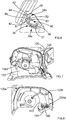
- Figs. 1 and 2 illustrate a power tool, which in the embodiment described hereafter is a wall chaser 10.
- Fig. 1 illustrates the wall chaser 10 in a ready-to-use configuration
- Fig. 2 illustrates the wall chaser 10 in a cutting-disc-changing configuration.
- the wall chaser 10 has a rotatable support arrangement 12 for supporting a pair of cutting discs 14.
- the cutting discs 14 can be mounted to a shaft 16 of the support arrangement 12 in a manner familiar to persons skilled in the art.
- the cutting discs 14 can be placed around the shaft 16 with a spacer element between them, wherein a nut 18 is then threaded onto the shaft 16.
- the action of threading the nut 18 onto the shaft 16 causes the first cutting disc to be mounted on the shaft 16 to be essentially sandwiched between a supporting flange of the wall chaser 10 and a first side of the spacer element, whereas the second cutting disc to be mounted on the shaft 16 will be essentially sandwiched between a second side of the spacer element and the nut 18.
- the cutting discs 14 are thus rotationally locked relative to the shaft 16 such that upon an electric motor of the wall chaser 10 causing the shaft 16 to rotate the cutting discs 14 will be rotationally driven as well.
- spacer elements can be used depending on the required distance between the cutting discs 14. For example in another usage implementation the spacer element used could be shorter in length thereby providing a smaller distance between the cutting discs 14. Alternatively the spacer element used could be longer in length (or more than one spacer element could be used) thereby providing a greater distance between the cutting discs 14.
- An upper shroud member 20 and a lower shroud member 22 cooperate to define a volume in which the cutting discs 14 can be supported.
- the shaft 16 extends from an internal surface of the upper shroud member 20 such that movement of the upper shroud member 20 towards the lower shroud member 22 causes the cutting discs 14 to protrude through an opening 24 in the lower shroud member 22; this opening 24 extending through the base of the wall chaser 10 which is engaged with a work surface in use as shown in Fig. 1 . In this manner the cutting discs 14 can be brought into engagement with a work surface e.g. a masonry surface in use.
- the upper shroud member 20 is pivotally coupled to the lower shroud member 22.
- Biasing means urges the upper shroud member 20 and the lower shroud member 22 away from each other.
- the biasing means is a torsion spring 26.
- the lower shroud member 22 has a pair of flanges 28, 30 each having an opening extending therethrough.
- a bolt member 32 extends through these openings, wherein the torsion spring 26 wraps around the bolt member 32 in the space between the flanges 28, 30.
- a first arm 26a of the torsion spring 26 is for urging against the lower shroud member 22 and a second arm 26b of the torsion spring 26 is for urging against the upper shroud member 20.
- the upper shroud member 20 is pivotally coupled to the lower shroud member 22 so when a user pivots such members towards each other the torsion spring 26 is compressed, wherein upon releasing such members the torsion spring 26 urges them apart.
- the connecting element 19 the feature of the upper shroud member 20 which the second arm 26b of the torsion spring 26 urges against is the connecting element 19.
- one hand of a user grips the primary handle 11 in use, whereas the other hand grasps secondary handle 13.
- Pushing downwards on the secondary handle 13 in use causes the upper shroud member 20 to pivot towards the lower shroud member 22 and the cutting discs 14 to plunge into the masonry surface to be cut.
- Various internal features required for the wall chaser 10 to function as heretofore described will be apparent to persons skilled in the art, including a battery for powering an electric motor and a power train for transferring torque from the electric motor to the shaft 16 for rotating the cutting discs 14.
- a trigger 15 is provided on the primary handle 11 for enabling a user to selectively cause actuation of the electric motor and thereby rotation of the cutting discs 14.
- the upper shroud member 20 is formed of two parts, a first shroud part 20a and a second shroud part 20b which are coupled together via a hinge coupling 25.
- the upper shroud member 20 can thus be reconfigured between a closed configuration as in Fig. 1 and an open configuration as in Fig. 2 .
- the first shroud part 20a and the second shroud part 20b are maintained in a closed configuration by a securing mechanism that can be selectively released by a user.
- the securing mechanism comprises a first latch part 27a on the first shroud part 20a that can be releasably coupled to a second latch part 27b on the second shroud part 20b but other suitable mechanisms will be apparent to persons skilled in the art.
- a limiting mechanism is provided for limiting the range of pivotal movement of the upper shroud member 20 relative to the lower shroud member 22 under action of the torsion spring 26 when the upper shroud part 20 is in the closed configuration.
- a first part 34a of the limiting mechanism is carried by the upper shroud member 20 and a second part 34b of the limiting mechanism is carried by the lower shroud member 22.
- the first part 34a of the limiting mechanism is provided on an internal surface of the upper shroud member 20, in the embodiment shown on the internal surface of the second shroud part 20b.
- the view in Fig. 6 includes a cross sectional view of the second shroud part 20b, otherwise the outer surface thereof would obscure the features extending from its internal surface.
- Protrusions 36 extending from the internal surface of the second shroud part 20b cooperate to define a substantially L-shaped channel 37, wherein an opening 38 is left in communication with the channel 37.
- a metallic spring feature 40 is received in the channel 37 and maintained therein by interference fit with the internal surfaces of the protrusions 36.
- the metallic spring feature 40 extends from the channel 37 via the opening 38.
- the metallic spring feature 40 has a first section 42 that extends from the opening 38 of the channel 37 into contact with a blocking surface 44.
- the blocking surface 44 is defined by a feature 46 coupled to the internal surface of the upper shroud member 20, in the embodiment shown on the internal surface of the second shroud part 20b.
- the metallic spring feature 40 also has a second section 43 that extends away from the blocking surface 44.
- the first and second sections 42, 43 of the metallic spring feature 40 define an acute angle A between them.
- the second part 34b of the limiting mechanism is carried by the lower shroud member 22 and comprises a rigid feature integrally formed with the lower shroud member 22.
- the rigid feature 34b has a first surface 48 and a second surface 50, wherein the second surface 50 has a larger surface area than the first surface 48.
- a ramped portion 52 is provided between such first and second surfaces 48, 50.
- FIG. 2 consider the scenario in which a user closes the upper shroud member 20 and then urges the upper shroud member 20 towards the lower shroud member 22. This involves the user closing the first and second parts 20a, 20b of the upper shroud member 20 and securing the first latch part 27a to the second latch part 27b. Upon subsequently pivoting the upper shroud member 20 towards the lower shroud member 22, against bias of the torsion spring 26, the first section 42 of the metallic spring feature 40 carried by the upper shroud member 20 will be brought into engagement with the first surface 48 of the rigid feature 34b carried by the lower shroud member 22.
- the rigid feature 34b Upon further pivoting the upper shroud member 20 more towards the lower shroud member 22 the rigid feature 34b cooperates with the metallic spring feature 40 to cause deflection of the metallic spring feature 40.
- the metallic spring feature 40 is caused to recoverably flex by the rigid feature 34b thus enabling such features to move passed each other.
- the upper shroud member 20 can thus be pivoted further towards the lower shroud member 22 by a user against bias of the torsion spring 26.
- the first section 42 of the metallic spring feature 40 is configured to be ramped relative to the first surface 48 of the rigid feature 34b when they initially engage. This reduces the extent of deflection required by the metallic spring feature 40 to move passed the rigid feature 34b compared to if the first section 42 of the metallic spring feature 40 simply extended directly from the opening 38 along the axis of the channel 37.
- the torsion spring 26 will urge such members apart.
- the second section 43 of the metallic spring feature 40 carried by the upper shroud member 20 is brought into engagement with the second surface 50 of the rigid feature 34b carried by the lower shroud member 22.
- the second surface 50 of the rigid feature 34b thus cooperates with the metallic spring feature 40 to cause deflection of the metallic spring feature 40 in the opposite direction to that heretofore described, however, the extent of such deflection is limited by the blocking surface 44.
- the blocking surface 44 prevents the spring element 40 from deflecting sufficiently to enable it to move passed the rigid feature 34b as the upper shroud member 20 is pivoted away from the lower shroud member 22 under bias of the torsion spring 26.
- the extent of pivotal movement of the upper shroud member 20 relative to the lower shroud member 22 is thereby restricted.
- the blocking surface acts as heretofore described to restrict the lower shroud member 22 from falling away from the upper shroud member 20 under gravity when a user lifts the tool up.
- parts of the wall chaser 10 can pivot about two axes of freedom.
- the first such axis 45 is defined by the hinge coupling 25 and the second such axis 47 is defined by the pivotal connection between the upper and lower shroud members, wherein such axes are orthogonal relative to each other.
- Users of the wall chaser 10 are thus provided with quick and easy access to the cutting discs 14 mounted to the shaft 16 for facilitating their replacement or otherwise e.g. changing the distance between the cutting discs 14 by modifying the arrangement of spacer elements heretofore described which will be familiar to persons skilled in the art.
- features of the wall chaser 10 merely hinge apart to enable blade replacement the risk of a user losing a feature or not reassembling it correctly is reduced.
- the wall chaser 10 can be reconfigured into its ready-to-use configuration illustrated in Fig. 1 in multiple ways. For example, starting from the configuration illustrated in Fig. 2 a user may secure the first and second shroud parts 20a, 20b of the upper shroud member 20 and then urge the upper shroud member 20 towards the lower shroud member 22 to engage the limiting mechanism as heretofore described.
- a user may urge the first shroud member 20 towards the lower shroud member 22 against the torsion spring 26 by pushing down on the secondary handle 13. Subsequently the user may then secure the first and second shroud parts 20a, 20b of the upper shroud member 20 together before releasing the pressure exerted against the torsion spring 26. On releasing such pressure the upper shroud member 20 will be pivoted away from the lower shroud member 22 by the torsion spring 26, thereby engaging the second section 43 of the metallic spring feature 40 with the second surface 50 of the rigid member 34b for restricting further pivotal movement of the shroud members away from each other under bias of the torsion spring (and gravity when the tool is lifted).
- the blocking surface 44 is not defined by a feature 46 coupled to the internal surface of the upper shroud member 20, whereas instead it is merely an internal surface of the shroud part which carries the metallic spring feature 40 e.g. the inner surface of the shroud part or a flange integrally formed with the shroud part.
- the blocking surface 44 is a rib integrally formed with the upper shroud member 20 and extending from an inner surface thereof.
- first and second heretofore mentioned axes 45, 47 defining the degrees of freedom of movement of respective features of the wall chaser 10 have been described as being orthogonal relative to each other, in some embodiments this need not necessarily be the case provided the wall chaser 10 can be opened and closed in substantially the same manner for cutting disc replacement i.e. opening the upper shroud member 20 disengages the limiting mechanism.
- the connecting element 19 couples directly to the first shroud part 20a of the upper shroud member 20, thus providing that only the second shroud part 20b moves about the hinge connection 25.
- the connecting element 19 may be shaped such that both the first shroud part 20a and the second shroud part 20b are separately coupled thereto about respective hinge couplings.
- the first shroud part 20a may be coupled to the connecting element 19 via a first hinge coupling and the second shroud part 20b may be coupled to the connecting element 19 via a second hinge coupling; thereby providing that in such embodiments both the first and second shroud parts 20a, 20b can be hingedly moved relative to each other in order to open the upper shroud member 20.
- protrusions 36, metallic spring feature 40 and blocking surface 44 have been described as carried by the upper shroud member 20; and the rigid feature 34b has been described as carried by the lower shroud member 22; it will be appreciated that such an arrangement could be reversed.
- the protrusions 36, the metallic spring feature 40 and the blocking surface 44 could alternatively be carried by the lower shroud member 22; and the rigid feature 34b could alternatively be carried by the upper shroud member 20 provided that the rigid feature 34b is capable of being disengaged from the metallic spring feature 40 when the shroud parts of the upper shroud member 20 are opened relative to each other.
- the spring feature 40 need not necessarily be metallic and could be plastic or rubber for example, provided it is able to perform the same function as the metallic spring feature 40 heretofore described.
- an alternative biasing means could be used such as a cap spring, coil spring, clock spring or pressure spring.
- the second part 134b of the limiting mechanism carried by the lower shroud member 122 may be a rod or pin feature extending from the lower shroud 122.
- the metallic spring feature 140 cooperates with a blocking surface 144 formed by a rib extending from an internal surface of the second shroud part 120b.
- the rod or pin feature Upon closing the first and second shroud parts 120a, 120b and pushing the upper shroud member 120 towards the lower shroud member 122 against spring bias as heretofore described, the rod or pin feature will cooperate with the metallic spring portion 140 causing it to deflect and move past the rod or pin feature and spring back to its original configuration.
- the spring bias will cause the section 143 of the metallic spring feature 140 to engage the rod or pin feature which will urge it into contact with the blocking surface 144, thereby restricting the spring bias from being able to urge the upper and lower shroud members 120, 122 apart.
- the blocking surface 144 acts as to restrict the lower shroud member 122 from falling away from the upper shroud member 120 under gravity when a user lifts the tool up.
- the mechanism can be released by opening the upper shroud member 120 via the hinge opening 125.
Landscapes
- Engineering & Computer Science (AREA)
- Mechanical Engineering (AREA)
- Processing Of Stones Or Stones Resemblance Materials (AREA)
- Sawing (AREA)
Abstract
Description
- This specification concerns facilitating a user to replace rotatable cutting discs of a power tool, for example a wall chaser.
- European patent number
EP2552660B1 describes a wall chaser, which is a power tool for forming channels in a concrete surface. Objects such as cables and wires can be fed through such channels during a construction project. Wall chasers are known to carry a pair of axially offset cutting discs which in use form two parallel slots in a concrete surface. Subsequently a construction worker is required to chisel away the concrete remaining between such slots, thereby leaving a channel of the kind heretofore mentioned. It will be appreciated that the cutting discs are subject to wear and need replacing from time-to-time. Wall chaser products are known in which users must partially disassemble their wall chaser product, in other words physically separate respective parts thereof, to enable user access to the cutting discs for replacement or for other reasons e.g. to change the distance between cutting discs and thus cutting width. Furthermore, some wall chaser products require surprisingly high levels of dexterity to access the cutting discs thereof and can be difficult to open up in order to provide user access to the cutting discs for replacement or otherwise. Aspects of the present invention are conceived to address the foregoing. - According to an aspect of the present invention there is provided a power tool comprising: a rotatable support arrangement for supporting at least one cutting disc and being configured to be rotatably driven by an electric motor; an upper shroud member and a lower shroud member which cooperate to define a volume in which the at least one cutting disc can be supported, the rotatable support arrangement coupled to the upper shroud member such that movement of the upper shroud member towards the lower shroud member causes said at least one cutting disc to protrude through an opening in the lower shroud member; biasing means for urging the upper shroud member and the lower shroud member away from each other; a limiting mechanism for limiting the range of movement of the upper shroud member relative to the lower shroud member under action of the biasing means, a first part thereof being carried by the upper shroud member and a second part thereof being carried by the lower shroud member; wherein the limiting mechanism can be disengaged by opening the upper shroud member via at least one hinge coupling, thereby increasing the range of relative movement of the upper and lower shroud members.
- The upper shroud member may comprise a first shroud part and a second shroud part that are configured to move relative to each other via at least one said hinge coupling.
- The first shroud part and the second shroud part may be configured to move relative to each other via a single hinge coupling.
- The upper and lower shroud members may be configured to pivot relative to each other about a first axis and the or each said hinge coupling may permit relative movement between the first and second shroud parts about a respective axis orthogonal to the first axis.
- The first shroud part and the second shroud part may be maintained in a closed configuration by a securing mechanism that can be selectively released by a user.
- The limiting mechanism may be configured such that when the first and second parts thereof are urged against each other upon a user moving the upper and lower shroud members towards each other one of the first and second parts of the limiting mechanism causes the other to recoverably flex so that they can move past each other, however, upon the first and second parts of the limiting mechanism being subsequently brought back into contact with each other under action of the biasing means urging the upper and lower shroud members away from each other the first and second parts of the limiting mechanism restrict the extent to which the upper and lower shroud members can be moved away from each other under action of the biasing means.
- The first and second parts of the limiting mechanism may comprise a spring feature that defines a first surface along which the other of the first and second parts of the limiting mechanism can ride for facilitating such parts to move passed each other when urged against each other upon a user moving the upper and lower shroud members towards each other, the spring feature also defining a second surface against which the other of the first and second parts of the limiting mechanism can rest when such parts are subsequently brought back into contact with each other under action of the biasing means urging the upper and lower shroud members away from each other.
- A blocking feature of the shroud part carrying the spring feature may block deflection of the spring feature when said other of the first and second parts of the limiting mechanism urges against the second surface of the spring feature under action of the biasing means urging the upper and lower shroud members away from each other, thereby limiting the extent to which the upper and lower shroud members can move away from each other.
- The blocking feature may be an integral internal surface of the shroud part which carries the spring feature or is a feature coupled to that shroud part.
- The spring feature may be metallic.
- Said other of the first and second parts of the limiting mechanism for cooperating with the spring feature may comprise a rigid feature having a first surface for engaging the first surface of the spring feature and a second surface for engaging the second surface of the spring feature, optionally the second surface of the rigid feature having a larger surface area than the first surface thereof.
- The rigid feature may further comprise a ramped portion between the first surface thereof and the second surface thereof.
- Said other of the first and second parts of the limiting mechanism for cooperating with the spring feature may comprise a rigid feature having a rod like shape.
- The rigid feature may be an integral part of the shroud member not carrying the spring feature.
- The heretofore described tool may be a rotary cutting tool for cutting masonry, optionally wherein the tool is a wall chaser.
- Various aspects and embodiments of the invention will now be described by way of non-limiting example with reference to the accompanying drawings, in which:
-
Fig. 1 illustrates a power tool according to an embodiment of the present invention in a ready-to-use configuration; -
Fig. 2 illustrates the power tool ofFig. 1 in a cutting-disc-changing configuration; -
Fig. 3 illustrates a torsion spring of the power tool inFig. 1 ; -
Fig. 4 illustrates the torsion spring ofFig. 3 included in the power tool ofFig. 1 ; -
Fig. 5 illustrates a plan view of an internal surface of the second shroud part of the upper shroud member of the power tool inFig. 1 ; -
Fig. 6 illustrates how first and second parts of the limiting mechanism of the power tool inFig. 1 cooperate in use; and -
Figs. 7 and 8 illustrate features of the limiting mechanism of a second embodiment. -
Figs. 1 and 2 illustrate a power tool, which in the embodiment described hereafter is awall chaser 10.Fig. 1 illustrates thewall chaser 10 in a ready-to-use configuration andFig. 2 illustrates thewall chaser 10 in a cutting-disc-changing configuration. - The
wall chaser 10 has arotatable support arrangement 12 for supporting a pair ofcutting discs 14. Thecutting discs 14 can be mounted to ashaft 16 of thesupport arrangement 12 in a manner familiar to persons skilled in the art. For example, thecutting discs 14 can be placed around theshaft 16 with a spacer element between them, wherein anut 18 is then threaded onto theshaft 16. The action of threading thenut 18 onto theshaft 16 causes the first cutting disc to be mounted on theshaft 16 to be essentially sandwiched between a supporting flange of thewall chaser 10 and a first side of the spacer element, whereas the second cutting disc to be mounted on theshaft 16 will be essentially sandwiched between a second side of the spacer element and thenut 18. Thecutting discs 14 are thus rotationally locked relative to theshaft 16 such that upon an electric motor of thewall chaser 10 causing theshaft 16 to rotate thecutting discs 14 will be rotationally driven as well. It will be appreciated that various configurations and combinations of spacer elements can be used depending on the required distance between thecutting discs 14. For example in another usage implementation the spacer element used could be shorter in length thereby providing a smaller distance between thecutting discs 14. Alternatively the spacer element used could be longer in length (or more than one spacer element could be used) thereby providing a greater distance between thecutting discs 14. - An
upper shroud member 20 and alower shroud member 22 cooperate to define a volume in which thecutting discs 14 can be supported. Theshaft 16 extends from an internal surface of theupper shroud member 20 such that movement of theupper shroud member 20 towards thelower shroud member 22 causes thecutting discs 14 to protrude through anopening 24 in thelower shroud member 22; this opening 24 extending through the base of thewall chaser 10 which is engaged with a work surface in use as shown inFig. 1 . In this manner thecutting discs 14 can be brought into engagement with a work surface e.g. a masonry surface in use. - The
upper shroud member 20 is pivotally coupled to thelower shroud member 22. Biasing means urges theupper shroud member 20 and thelower shroud member 22 away from each other. In this embodiment the biasing means is atorsion spring 26. With reference toFig. 4 thelower shroud member 22 has a pair offlanges bolt member 32 extends through these openings, wherein thetorsion spring 26 wraps around thebolt member 32 in the space between theflanges first arm 26a of thetorsion spring 26 is for urging against thelower shroud member 22 and asecond arm 26b of thetorsion spring 26 is for urging against theupper shroud member 20. Theupper shroud member 20 is pivotally coupled to thelower shroud member 22 so when a user pivots such members towards each other thetorsion spring 26 is compressed, wherein upon releasing such members thetorsion spring 26 urges them apart. Looking atFig. 2 the feature of theupper shroud member 20 which thesecond arm 26b of thetorsion spring 26 urges against is the connectingelement 19. - Referring back to
Fig 1 , one hand of a user grips theprimary handle 11 in use, whereas the other hand graspssecondary handle 13. Pushing downwards on thesecondary handle 13 in use causes theupper shroud member 20 to pivot towards thelower shroud member 22 and thecutting discs 14 to plunge into the masonry surface to be cut. Various internal features required for thewall chaser 10 to function as heretofore described will be apparent to persons skilled in the art, including a battery for powering an electric motor and a power train for transferring torque from the electric motor to theshaft 16 for rotating thecutting discs 14. Moreover, atrigger 15 is provided on theprimary handle 11 for enabling a user to selectively cause actuation of the electric motor and thereby rotation of thecutting discs 14. - The
upper shroud member 20 is formed of two parts, afirst shroud part 20a and asecond shroud part 20b which are coupled together via ahinge coupling 25. Theupper shroud member 20 can thus be reconfigured between a closed configuration as inFig. 1 and an open configuration as inFig. 2 . Thefirst shroud part 20a and thesecond shroud part 20b are maintained in a closed configuration by a securing mechanism that can be selectively released by a user. In this embodiment the securing mechanism comprises afirst latch part 27a on thefirst shroud part 20a that can be releasably coupled to asecond latch part 27b on thesecond shroud part 20b but other suitable mechanisms will be apparent to persons skilled in the art. - A limiting mechanism is provided for limiting the range of pivotal movement of the
upper shroud member 20 relative to thelower shroud member 22 under action of thetorsion spring 26 when theupper shroud part 20 is in the closed configuration. Afirst part 34a of the limiting mechanism is carried by theupper shroud member 20 and asecond part 34b of the limiting mechanism is carried by thelower shroud member 22. - With reference to
Figs. 5 and6 thefirst part 34a of the limiting mechanism is provided on an internal surface of theupper shroud member 20, in the embodiment shown on the internal surface of thesecond shroud part 20b. The view inFig. 6 includes a cross sectional view of thesecond shroud part 20b, otherwise the outer surface thereof would obscure the features extending from its internal surface.Protrusions 36 extending from the internal surface of thesecond shroud part 20b cooperate to define a substantially L-shapedchannel 37, wherein anopening 38 is left in communication with thechannel 37. Ametallic spring feature 40 is received in thechannel 37 and maintained therein by interference fit with the internal surfaces of theprotrusions 36. Themetallic spring feature 40 extends from thechannel 37 via theopening 38. - The
metallic spring feature 40 has afirst section 42 that extends from theopening 38 of thechannel 37 into contact with a blockingsurface 44. In this embodiment the blockingsurface 44 is defined by afeature 46 coupled to the internal surface of theupper shroud member 20, in the embodiment shown on the internal surface of thesecond shroud part 20b. Themetallic spring feature 40 also has asecond section 43 that extends away from the blockingsurface 44. The first andsecond sections metallic spring feature 40 define an acute angle A between them. The purpose of these specific features will become apparent upon reading further. - With continued reference to
Figs. 5 and6 thesecond part 34b of the limiting mechanism is carried by thelower shroud member 22 and comprises a rigid feature integrally formed with thelower shroud member 22. Therigid feature 34b has afirst surface 48 and asecond surface 50, wherein thesecond surface 50 has a larger surface area than thefirst surface 48. A rampedportion 52 is provided between such first andsecond surfaces - Looking at
Fig. 2 , consider the scenario in which a user closes theupper shroud member 20 and then urges theupper shroud member 20 towards thelower shroud member 22. This involves the user closing the first andsecond parts upper shroud member 20 and securing thefirst latch part 27a to thesecond latch part 27b. Upon subsequently pivoting theupper shroud member 20 towards thelower shroud member 22, against bias of thetorsion spring 26, thefirst section 42 of themetallic spring feature 40 carried by theupper shroud member 20 will be brought into engagement with thefirst surface 48 of therigid feature 34b carried by thelower shroud member 22. Upon further pivoting theupper shroud member 20 more towards thelower shroud member 22 therigid feature 34b cooperates with themetallic spring feature 40 to cause deflection of themetallic spring feature 40. In other words, themetallic spring feature 40 is caused to recoverably flex by therigid feature 34b thus enabling such features to move passed each other. Theupper shroud member 20 can thus be pivoted further towards thelower shroud member 22 by a user against bias of thetorsion spring 26. - Looking at
Fig. 6 thefirst section 42 of themetallic spring feature 40 is configured to be ramped relative to thefirst surface 48 of therigid feature 34b when they initially engage. This reduces the extent of deflection required by themetallic spring feature 40 to move passed therigid feature 34b compared to if thefirst section 42 of themetallic spring feature 40 simply extended directly from theopening 38 along the axis of thechannel 37. - With continued reference to
Fig. 2 upon a user subsequently refraining from urging theupper shroud member 20 towards thelower shroud member 22 against bias of thetorsion spring 26 thetorsion spring 26 will urge such members apart. As theupper shroud member 20 pivots away from thelower shroud member 22 under bias of thetorsion spring 26 thesecond section 43 of themetallic spring feature 40 carried by theupper shroud member 20 is brought into engagement with thesecond surface 50 of therigid feature 34b carried by thelower shroud member 22. Thesecond surface 50 of therigid feature 34b thus cooperates with themetallic spring feature 40 to cause deflection of themetallic spring feature 40 in the opposite direction to that heretofore described, however, the extent of such deflection is limited by the blockingsurface 44. In other words, the blockingsurface 44 prevents thespring element 40 from deflecting sufficiently to enable it to move passed therigid feature 34b as theupper shroud member 20 is pivoted away from thelower shroud member 22 under bias of thetorsion spring 26. The extent of pivotal movement of theupper shroud member 20 relative to thelower shroud member 22 is thereby restricted. Moreover the blocking surface acts as heretofore described to restrict thelower shroud member 22 from falling away from theupper shroud member 20 under gravity when a user lifts the tool up. - It is here mentioned that when the
upper shroud member 20 is at its upper limit of pivotal movement away from the lower shroud member 22 (defined by engagement between thesecond section 43 of themetallic spring feature 40 and thesecond surface 50 of therigid feature 34b as heretofore described) the cuttingdiscs 14 carried by thewall chaser 10 do not protrude through theopening 24 in the base thereof. The cuttingdiscs 14 only protrude through theopening 24 in the base of thewall chaser 10 when a user urges theupper shroud member 20 towards thelower shroud member 22 against bias of thetorsion spring 26 in use. - To enable replacement of the cutting discs 14 a user must release the first and
second latch parts upper shroud member 20. On doing so thesecond shroud part 20b can be pivoted away from thefirst shroud part 20a about thehinge coupling 25, thereby themetallic spring feature 40 carried by theupper shroud member 20 is moved out of engagement withrigid feature 34b carried by thelower shroud member 22. The heretofore described limiting mechanism is thus disengaged and the extent of pivotal movement between theupper shroud member 20 andlower shroud member 22 is increased. In the open configuration of theupper shroud member 20, when a user holds thewall chaser 10 from only thesecondary handle 13 thelower shroud part 22 pivots away from theupper shroud part 20 under the influence of gravity and bias of thetorsion spring 26. - With further reference to
Fig. 2 when theupper shroud part 20 is in the open configuration, parts of thewall chaser 10 can pivot about two axes of freedom. The firstsuch axis 45 is defined by thehinge coupling 25 and the secondsuch axis 47 is defined by the pivotal connection between the upper and lower shroud members, wherein such axes are orthogonal relative to each other. Users of thewall chaser 10 are thus provided with quick and easy access to the cuttingdiscs 14 mounted to theshaft 16 for facilitating their replacement or otherwise e.g. changing the distance between the cuttingdiscs 14 by modifying the arrangement of spacer elements heretofore described which will be familiar to persons skilled in the art. Also since features of thewall chaser 10 merely hinge apart to enable blade replacement the risk of a user losing a feature or not reassembling it correctly is reduced. - Lastly it is pointed out that after a cutting disc replacement operation the
wall chaser 10 can be reconfigured into its ready-to-use configuration illustrated inFig. 1 in multiple ways. For example, starting from the configuration illustrated inFig. 2 a user may secure the first andsecond shroud parts upper shroud member 20 and then urge theupper shroud member 20 towards thelower shroud member 22 to engage the limiting mechanism as heretofore described. - Alternatively, starting from the configuration illustrated in
Fig. 2 a user may urge thefirst shroud member 20 towards thelower shroud member 22 against thetorsion spring 26 by pushing down on thesecondary handle 13. Subsequently the user may then secure the first andsecond shroud parts upper shroud member 20 together before releasing the pressure exerted against thetorsion spring 26. On releasing such pressure theupper shroud member 20 will be pivoted away from thelower shroud member 22 by thetorsion spring 26, thereby engaging thesecond section 43 of themetallic spring feature 40 with thesecond surface 50 of therigid member 34b for restricting further pivotal movement of the shroud members away from each other under bias of the torsion spring (and gravity when the tool is lifted). - In some embodiments the blocking
surface 44 is not defined by afeature 46 coupled to the internal surface of theupper shroud member 20, whereas instead it is merely an internal surface of the shroud part which carries themetallic spring feature 40 e.g. the inner surface of the shroud part or a flange integrally formed with the shroud part. In some embodiments the blockingsurface 44 is a rib integrally formed with theupper shroud member 20 and extending from an inner surface thereof. - Although the first and second heretofore mentioned
axes wall chaser 10 have been described as being orthogonal relative to each other, in some embodiments this need not necessarily be the case provided thewall chaser 10 can be opened and closed in substantially the same manner for cutting disc replacement i.e. opening theupper shroud member 20 disengages the limiting mechanism. - Looking at
Fig. 2 the connectingelement 19 couples directly to thefirst shroud part 20a of theupper shroud member 20, thus providing that only thesecond shroud part 20b moves about thehinge connection 25. In some embodiments the connectingelement 19 may be shaped such that both thefirst shroud part 20a and thesecond shroud part 20b are separately coupled thereto about respective hinge couplings. In other words, thefirst shroud part 20a may be coupled to the connectingelement 19 via a first hinge coupling and thesecond shroud part 20b may be coupled to the connectingelement 19 via a second hinge coupling; thereby providing that in such embodiments both the first andsecond shroud parts upper shroud member 20. - Although the
protrusions 36,metallic spring feature 40 and blockingsurface 44 have been described as carried by theupper shroud member 20; and therigid feature 34b has been described as carried by thelower shroud member 22; it will be appreciated that such an arrangement could be reversed. For example, theprotrusions 36, themetallic spring feature 40 and the blockingsurface 44 could alternatively be carried by thelower shroud member 22; and therigid feature 34b could alternatively be carried by theupper shroud member 20 provided that therigid feature 34b is capable of being disengaged from themetallic spring feature 40 when the shroud parts of theupper shroud member 20 are opened relative to each other. - In some embodiments the
spring feature 40 need not necessarily be metallic and could be plastic or rubber for example, provided it is able to perform the same function as themetallic spring feature 40 heretofore described. - Although the foregoing embodiments are described as including a
torsion spring 26 for urging theupper shroud member 20 away from thelower shroud member 22 in some embodiments an alternative biasing means could be used such as a cap spring, coil spring, clock spring or pressure spring. - It will be appreciated that in other embodiments, respective features need not necessarily have the same shape and configuration of the parts heretofore described provided they achieve the same function. For example, with reference to
Figs. 7 and 8 (wherein like features are denoted with similar reference numerals to those used up to now but increased by 100) in one embodiment thesecond part 134b of the limiting mechanism carried by thelower shroud member 122 may be a rod or pin feature extending from thelower shroud 122. As for thefirst part 134a of the limiting mechanism carried by the upper shroud member themetallic spring feature 140 cooperates with a blockingsurface 144 formed by a rib extending from an internal surface of thesecond shroud part 120b. Upon closing the first andsecond shroud parts upper shroud member 120 towards thelower shroud member 122 against spring bias as heretofore described, the rod or pin feature will cooperate with themetallic spring portion 140 causing it to deflect and move past the rod or pin feature and spring back to its original configuration. Upon a user refraining from pushing theupper shroud member 120 towards thelower shroud member 122 the spring bias will cause thesection 143 of themetallic spring feature 140 to engage the rod or pin feature which will urge it into contact with the blockingsurface 144, thereby restricting the spring bias from being able to urge the upper andlower shroud members surface 144 acts as to restrict thelower shroud member 122 from falling away from theupper shroud member 120 under gravity when a user lifts the tool up. The mechanism can be released by opening theupper shroud member 120 via thehinge opening 125. - Although the foregoing is described in the specific context of a
wall chaser 10 it will be appreciated that the teachings herein could be applied in the context of other power tools having rotatable cutting discs that are shielded from user access in use but that a user must have access to in order to replace them, e.g. circular saw power tools. It will thus further be appreciated that in some embodiments the power tool in which the foregoing teachings are applied could have only a single cutting disc. Finally, it will be appreciated that whilst various aspects and embodiments have heretofore been described, the scope of the present invention is not limited thereto and instead extends to encompass all arrangements, and modifications and alterations thereto, which fall within the spirit and scope of the appended claims.
Claims (15)
- A power tool comprising:a rotatable support arrangement for supporting at least one cutting disc and being configured to be rotatably driven by an electric motor;an upper shroud member and a lower shroud member which cooperate to define a volume in which the at least one cutting disc can be supported, the rotatable support arrangement coupled to the upper shroud member such that movement of the upper shroud member towards the lower shroud member causes said at least one cutting disc to protrude through an opening in the lower shroud member;biasing means for urging the upper shroud member and the lower shroud member away from each other;a limiting mechanism for limiting the range of movement of the upper shroud member relative to the lower shroud member under action of the biasing means, a first part thereof being carried by the upper shroud member and a second part thereof being carried by the lower shroud member;wherein the limiting mechanism can be disengaged by opening the upper shroud member via at least one hinge coupling, thereby increasing the range of relative movement of the upper and lower shroud members.
- The power tool of claim 1 wherein the upper shroud member comprises a first shroud part and a second shroud part that are configured to move relative to each other via at least one said hinge coupling.
- The power tool of claim 2 wherein the first shroud part and the second shroud part are configured to move relative to each other via a single hinge coupling.
- The power tool of claim 2 or 3 wherein the upper and lower shroud members are configured to pivot relative to each other about a first axis and the or each said hinge coupling permits relative movement between the first and second shroud parts about a respective axis orthogonal to the first axis.
- The power tool of any of claims 2 to 4 wherein the first shroud part and the second shroud part are maintained in a closed configuration by a securing mechanism that can be selectively released by a user.
- The power tool of any preceding claim wherein the limiting mechanism is configured such that when the first and second parts thereof are urged against each other upon a user moving the upper and lower shroud members towards each other one of the first and second parts of the limiting mechanism causes the other to recoverably flex so that they can move past each other, however, upon the first and second parts of the limiting mechanism being subsequently brought back into contact with each other under action of the biasing means urging the upper and lower shroud members away from each other the first and second parts of the limiting mechanism restrict the extent to which the upper and lower shroud members can be moved away from each other under action of the biasing means.
- The power tool of claim 6 wherein one of the first and second parts of the limiting mechanism comprises a spring feature that defines a first surface along which the other of the first and second parts of the limiting mechanism can ride for facilitating such parts to move passed each other when urged against each other upon a user moving the upper and lower shroud members towards each other, the spring feature also defining a second surface against which the other of the first and second parts of the limiting mechanism can rest when such parts are subsequently brought back into contact with each other under action of the biasing means urging the upper and lower shroud members away from each other.
- The power tool of claim 7 wherein a blocking feature of the shroud part carrying the spring feature blocks deflection of the spring feature when said other of the first and second parts of the limiting mechanism urges against the second surface of the spring feature under action of the biasing means urging the upper and lower shroud members away from each other, thereby limiting the extent to which the upper and lower shroud members can move away from each other.
- The power tool of claim 8 wherein the blocking feature is an integral internal surface of the shroud part which carries the spring feature or is a feature coupled to that shroud part.
- The power tool of any of claims 7 to 9 wherein the spring feature is metallic.
- The power tool of any of claims 7 to 10 wherein said other of the first and second parts of the limiting mechanism for cooperating with the spring feature comprises a rigid feature having a first surface for engaging the first surface of the spring feature and a second surface for engaging the second surface of the spring feature, optionally the second surface of the rigid feature having a larger surface area than the first surface thereof.
- The power tool of claim 11 wherein the rigid feature further comprises a ramped portion between the first surface thereof and the second surface thereof.
- The power tool of any of claims 7 to 10 wherein said other of the first and second parts of the limiting mechanism for cooperating with the spring feature comprises a rigid feature having a rod like shape.
- The power tool of claim 11, 12 or 13 wherein the rigid feature is an integral part of the shroud member not carrying the spring feature.
- The power tool of any preceding claim wherein the tool is a rotary cutting tool for cutting masonry, optionally wherein the tool is a wall chaser.
Priority Applications (4)
| Application Number | Priority Date | Filing Date | Title |
|---|---|---|---|
| EP18208929.2A EP3659763B1 (en) | 2018-11-28 | 2018-11-28 | Power tool |
| EP19185097.3A EP3659764B1 (en) | 2018-11-28 | 2019-07-09 | Power tool debris management |
| US16/691,028 US12179386B2 (en) | 2018-11-28 | 2019-11-21 | Power tool debris management |
| US16/690,986 US11440220B2 (en) | 2018-11-28 | 2019-11-21 | Replacement of rotatable cutting discs of a power tool |
Applications Claiming Priority (1)
| Application Number | Priority Date | Filing Date | Title |
|---|---|---|---|
| EP18208929.2A EP3659763B1 (en) | 2018-11-28 | 2018-11-28 | Power tool |
Publications (2)
| Publication Number | Publication Date |
|---|---|
| EP3659763A1 true EP3659763A1 (en) | 2020-06-03 |
| EP3659763B1 EP3659763B1 (en) | 2023-05-31 |
Family
ID=64604436
Family Applications (2)
| Application Number | Title | Priority Date | Filing Date |
|---|---|---|---|
| EP18208929.2A Active EP3659763B1 (en) | 2018-11-28 | 2018-11-28 | Power tool |
| EP19185097.3A Active EP3659764B1 (en) | 2018-11-28 | 2019-07-09 | Power tool debris management |
Family Applications After (1)
| Application Number | Title | Priority Date | Filing Date |
|---|---|---|---|
| EP19185097.3A Active EP3659764B1 (en) | 2018-11-28 | 2019-07-09 | Power tool debris management |
Country Status (2)
| Country | Link |
|---|---|
| US (2) | US11440220B2 (en) |
| EP (2) | EP3659763B1 (en) |
Families Citing this family (3)
| Publication number | Priority date | Publication date | Assignee | Title |
|---|---|---|---|---|
| DE202020003280U1 (en) * | 2020-07-30 | 2020-08-11 | Scheppach Fabrikation Von Holzbearbeitungsmaschinen Gmbh | Sawing machine |
| JP7754709B2 (en) * | 2021-12-22 | 2025-10-15 | 株式会社マキタ | Portable processing machine |
| JP2023114188A (en) * | 2022-02-04 | 2023-08-17 | 株式会社マキタ | wall chaser |
Citations (6)
| Publication number | Priority date | Publication date | Assignee | Title |
|---|---|---|---|---|
| US2801654A (en) * | 1954-04-08 | 1957-08-06 | Utz Friedrich | Guard for motor-driven hand circular saw |
| WO2011026302A1 (en) * | 2009-09-07 | 2011-03-10 | 宁波捷美进出口有限公司 | Hand-hold circular saw casing mechanism |
| EP2666592A1 (en) * | 2011-01-21 | 2013-11-27 | Nakaya Co., Ltd. | Hand-held electric cutting machine |
| EP2915639A1 (en) * | 2014-03-04 | 2015-09-09 | Eberhard Berhalter | Hand tool machine apparatus |
| EP2552660B1 (en) | 2010-03-31 | 2017-03-08 | Illinois Tool Works Inc. | Wall chaser |
| WO2018043330A1 (en) * | 2016-09-02 | 2018-03-08 | 株式会社マキタ | Working machine |
Family Cites Families (61)
| Publication number | Priority date | Publication date | Assignee | Title |
|---|---|---|---|---|
| US1880885A (en) * | 1927-02-21 | 1932-10-04 | Cromar Co | Sawing machine |
| US2789404A (en) * | 1955-01-11 | 1957-04-23 | Holman Brothers Ltd | Dust collecting |
| US3034493A (en) * | 1959-07-24 | 1962-05-15 | Charles R Bandy | Suction sawdust collector |
| US4022182A (en) * | 1976-01-12 | 1977-05-10 | Lenkevich Steve T | Dust and water confinement unit for portable circular saw |
| AU518436B2 (en) * | 1977-04-12 | 1981-10-01 | Builder Mate Products Pty. Ltd. | Power saw mounting |
| US4192104A (en) | 1978-10-10 | 1980-03-11 | Wilderness Mold, Inc. | Dust shroud |
| JPS6193206A (en) * | 1984-10-12 | 1986-05-12 | Hitachi Ltd | steam turbine nozzle box |
| DE3500371A1 (en) * | 1985-01-08 | 1986-07-10 | Licentia Patent-Verwaltungs-Gmbh, 6000 Frankfurt | Portable electric circular saw |
| DE3525092A1 (en) * | 1985-07-13 | 1987-01-22 | Festo Kg | Especially portable severing device, such as a hand-held circular saw, abrasive cutting device or the like |
| JPH0230215Y2 (en) | 1986-10-22 | 1990-08-14 | ||
| DE3843236A1 (en) * | 1988-12-22 | 1990-06-28 | Bosch Gmbh Robert | Circular saw |
| DE3921778A1 (en) * | 1989-07-01 | 1991-01-10 | Hilti Ag | HAND DEVICE WITH CUTTING OR GRINDING DISC |
| US5167215A (en) * | 1991-10-11 | 1992-12-01 | Equipment Development Co., Inc. | Dust removal apparatus for a concrete saw |
| DE4230642A1 (en) * | 1992-09-12 | 1994-03-17 | Bosch Gmbh Robert | Powered circular hand-saw with dust extraction system - has pendulum guard with resilient guide vanes which touch each side of saw blade and deflect sawdust towards suction aperture |
| US5327649A (en) * | 1993-02-11 | 1994-07-12 | Skinner Christopher L | Circular saw with dust collector |
| US5531147A (en) | 1993-11-23 | 1996-07-02 | Alpine Engineered Products, Inc. | Saw guard |
| JP3214295B2 (en) | 1995-05-12 | 2001-10-02 | 日立工機株式会社 | Portable dust collection circular saw |
| US5758425A (en) * | 1997-05-20 | 1998-06-02 | S-B Power Tool Company | Depth-of-cut mechanism for circular saw |
| US6108912A (en) * | 1998-12-23 | 2000-08-29 | Radigan; Michael C. | Dust collecting shield for power tools |
| DE10205378A1 (en) * | 2002-02-09 | 2003-08-21 | Bosch Gmbh Robert | Portable jigsaw |
| DE10261743A1 (en) * | 2002-12-30 | 2004-07-22 | Robert Bosch Gmbh | Manual circular saw B27B |
| US7526866B2 (en) * | 2003-10-31 | 2009-05-05 | Black & Decker Inc. | Variable dust chute for circular saws |
| JP4467964B2 (en) * | 2003-12-08 | 2010-05-26 | 株式会社マキタ | Dust collection circular saw |
| DE102004004003A1 (en) | 2004-01-27 | 2005-08-11 | Robert Bosch Gmbh | Chip collecting container and system comprising a chip collecting container and a protective hood for a machine tool |
| US20080244910A1 (en) * | 2004-05-28 | 2008-10-09 | Scientific Molding Corporation Ltd. | Hand-Held Circular Saw, In Particular Plunge-Cut Saw |
| DE602005010468D1 (en) | 2004-07-16 | 2008-11-27 | Makita Corp | Saw with dust collector |
| US7328512B2 (en) * | 2004-09-14 | 2008-02-12 | Martin Charles B | Self-contained vacuum saw |
| JP4733952B2 (en) * | 2004-09-24 | 2011-07-27 | 株式会社マキタ | Cutting machine |
| DE102004047277A1 (en) | 2004-09-29 | 2006-04-06 | Hilti Ag | Cover device for a tool device |
| DE102005000143A1 (en) | 2005-10-21 | 2007-05-03 | Hilti Ag | covering |
| US20070141160A1 (en) | 2005-12-15 | 2007-06-21 | Brown Laura J | Method of treatment for osteoarthritis by local intra-articular injection of microparticles |
| DE202006017585U1 (en) | 2006-11-17 | 2007-02-08 | Metabowerke Gmbh | Suction device for a motor-driven hand tool |
| DE102007011168B4 (en) * | 2007-03-07 | 2020-07-16 | Mafell Ag | Circular saw |
| JP5093464B2 (en) | 2007-07-17 | 2012-12-12 | 日立工機株式会社 | Portable cutting machine |
| DE102007000415A1 (en) | 2007-07-30 | 2009-02-05 | Hilti Aktiengesellschaft | Cover device of a tool device |
| JP5162262B2 (en) | 2008-01-22 | 2013-03-13 | 日立工機株式会社 | Protective cover and electric tool with protective cover |
| US8231435B2 (en) * | 2008-06-16 | 2012-07-31 | Donald Nevin | Sanitizing dental model trimmer |
| JP4466771B2 (en) * | 2008-07-07 | 2010-05-26 | パナソニック電工株式会社 | Electric circular saw |
| US20100058911A1 (en) | 2008-09-11 | 2010-03-11 | Jay Aaron Goddard | Blade Guard for Power Tool Having an Evacuation System |
| US8037610B2 (en) * | 2008-12-30 | 2011-10-18 | Crain Cutter Co., Inc. | Powered groover with airflow fin |
| AU2011210035B2 (en) | 2010-01-26 | 2016-12-15 | Husqvarna Ab | A laying machine |
| DE102010047529A1 (en) * | 2010-10-05 | 2012-04-05 | Wacker Neuson Produktion GmbH & Co. KG | Cutting-off machine with dust extraction |
| JP5215420B2 (en) * | 2011-02-08 | 2013-06-19 | 三笠産業株式会社 | Concrete cutting equipment |
| JP5739306B2 (en) | 2011-04-26 | 2015-06-24 | 株式会社マキタ | Dust collector for power tool and power tool |
| JP5774383B2 (en) * | 2011-06-16 | 2015-09-09 | 株式会社マキタ | CUTTING MACHINE COVER DEVICE AND CUTTING MACHINE WITH CUTTING COVER COVER DEVICE |
| US9855632B2 (en) | 2012-03-27 | 2018-01-02 | Robert Bosch Tool Corporation | Dust extraction system for a power tool |
| US9009982B1 (en) * | 2012-03-29 | 2015-04-21 | Simon J. Sedgwick | Dustless drywall cutting tool |
| US9610704B2 (en) * | 2012-12-11 | 2017-04-04 | Robert Bosch Tool Corporation | Circular saw blade guard with scratch-resistant panel |
| US10239173B2 (en) * | 2013-03-11 | 2019-03-26 | James Hardie Technology Limited | Cutting apparatus |
| WO2014151826A1 (en) | 2013-03-15 | 2014-09-25 | Robert Bosch Gmbh | Dust collection system for a circular saw |
| US20140366383A1 (en) * | 2013-06-13 | 2014-12-18 | Black & Decker Inc. | Blower for circular saw |
| AU2014385783B2 (en) | 2014-03-04 | 2019-08-29 | Techtronic Outdoor Products Technology Limited | A power tool with dust deflector |
| US9937638B2 (en) * | 2015-06-18 | 2018-04-10 | Makita Corporation | Dust collection cover for cutting devices |
| US10173345B2 (en) | 2015-06-18 | 2019-01-08 | Makita Corporation | Dust collection cover for cutting devices |
| DE102015008579A1 (en) * | 2015-06-26 | 2016-12-29 | Maschinenfabrik Otto Baier Gmbh | Processing device, in particular in the form of a diamond wall chaser |
| JP6596249B2 (en) * | 2015-07-21 | 2019-10-23 | 株式会社マキタ | Processing machine |
| GB201520055D0 (en) * | 2015-11-13 | 2015-12-30 | Black & Decker Inc | Saw |
| ES2630366B1 (en) * | 2016-02-17 | 2018-06-08 | Germans Boada, S.A. | COVER PROTECTION COVER FOR CUTTERS DISCS |
| US10751816B2 (en) * | 2016-02-17 | 2020-08-25 | Germans Boada, S.A. | Protective cooling cover for cutter discs |
| CA3082210A1 (en) * | 2016-11-16 | 2018-05-24 | Envirochasing Ip Holdings Pty Ltd | Extraction apparatus |
| WO2018195868A2 (en) * | 2017-04-27 | 2018-11-01 | 永康市丛臻工具有限公司 | Dust-free multifunctional cutting machine |
-
2018
- 2018-11-28 EP EP18208929.2A patent/EP3659763B1/en active Active
-
2019
- 2019-07-09 EP EP19185097.3A patent/EP3659764B1/en active Active
- 2019-11-21 US US16/690,986 patent/US11440220B2/en active Active
- 2019-11-21 US US16/691,028 patent/US12179386B2/en active Active
Patent Citations (6)
| Publication number | Priority date | Publication date | Assignee | Title |
|---|---|---|---|---|
| US2801654A (en) * | 1954-04-08 | 1957-08-06 | Utz Friedrich | Guard for motor-driven hand circular saw |
| WO2011026302A1 (en) * | 2009-09-07 | 2011-03-10 | 宁波捷美进出口有限公司 | Hand-hold circular saw casing mechanism |
| EP2552660B1 (en) | 2010-03-31 | 2017-03-08 | Illinois Tool Works Inc. | Wall chaser |
| EP2666592A1 (en) * | 2011-01-21 | 2013-11-27 | Nakaya Co., Ltd. | Hand-held electric cutting machine |
| EP2915639A1 (en) * | 2014-03-04 | 2015-09-09 | Eberhard Berhalter | Hand tool machine apparatus |
| WO2018043330A1 (en) * | 2016-09-02 | 2018-03-08 | 株式会社マキタ | Working machine |
Also Published As
| Publication number | Publication date |
|---|---|
| US20200164544A1 (en) | 2020-05-28 |
| US12179386B2 (en) | 2024-12-31 |
| US20200164449A1 (en) | 2020-05-28 |
| EP3659764A1 (en) | 2020-06-03 |
| EP3659763B1 (en) | 2023-05-31 |
| EP3659764B1 (en) | 2025-05-14 |
| US11440220B2 (en) | 2022-09-13 |
Similar Documents
| Publication | Publication Date | Title |
|---|---|---|
| US11440220B2 (en) | Replacement of rotatable cutting discs of a power tool | |
| TWI439358B (en) | Knife blade opening mechanism | |
| EP3919232B1 (en) | Power tool with multispeed transmission | |
| CN102886729B (en) | Electric tool | |
| US11904450B2 (en) | Multi-function pliers | |
| CN106475975B (en) | Hand-held tool and clamping device thereof | |
| JP2017113527A (en) | Manual pliers | |
| CN101786185A (en) | Portable cutter | |
| EP2940355B1 (en) | Valve with hinged valve element | |
| CN102802877B (en) | Powered tool | |
| KR200493409Y1 (en) | Chain saw for power tool | |
| DE112017004419T5 (en) | implement | |
| US20220063054A1 (en) | Power tool | |
| TWI236950B (en) | Belt-type grinding tool | |
| CN100589940C (en) | electrical tools | |
| EP3150333B1 (en) | Power tool with improved braking device | |
| CN201664788U (en) | Portable cutting machine | |
| US10323438B2 (en) | Two-point lock | |
| US9707677B2 (en) | Closure device | |
| US20110154967A1 (en) | Riving knife adjustment mechanism for a saw machine | |
| CN207272300U (en) | Electric circular saw | |
| KR102206144B1 (en) | Locking apparatus for valve | |
| CN104411470A (en) | Tool coupling device | |
| CN209615638U (en) | Cutting device for a barcode printer | |
| CN220362530U (en) | electrical tools |
Legal Events
| Date | Code | Title | Description |
|---|---|---|---|
| PUAI | Public reference made under article 153(3) epc to a published international application that has entered the european phase |
Free format text: ORIGINAL CODE: 0009012 |
|
| STAA | Information on the status of an ep patent application or granted ep patent |
Free format text: STATUS: THE APPLICATION HAS BEEN PUBLISHED |
|
| AK | Designated contracting states |
Kind code of ref document: A1 Designated state(s): AL AT BE BG CH CY CZ DE DK EE ES FI FR GB GR HR HU IE IS IT LI LT LU LV MC MK MT NL NO PL PT RO RS SE SI SK SM TR |
|
| AX | Request for extension of the european patent |
Extension state: BA ME |
|
| STAA | Information on the status of an ep patent application or granted ep patent |
Free format text: STATUS: REQUEST FOR EXAMINATION WAS MADE |
|
| 17P | Request for examination filed |
Effective date: 20201119 |
|
| RBV | Designated contracting states (corrected) |
Designated state(s): AL AT BE BG CH CY CZ DE DK EE ES FI FR GB GR HR HU IE IS IT LI LT LU LV MC MK MT NL NO PL PT RO RS SE SI SK SM TR |
|
| GRAP | Despatch of communication of intention to grant a patent |
Free format text: ORIGINAL CODE: EPIDOSNIGR1 |
|
| STAA | Information on the status of an ep patent application or granted ep patent |
Free format text: STATUS: GRANT OF PATENT IS INTENDED |
|
| INTG | Intention to grant announced |
Effective date: 20210428 |
|
| RIN1 | Information on inventor provided before grant (corrected) |
Inventor name: LAUER, ARTHUR Inventor name: MAERTE, ROBIN Inventor name: OEFFNER, ISABELL Inventor name: RIEDL, FABIAN Inventor name: SCHMIDT, BENJAMIN Inventor name: SELL, STEFAN |
|
| GRAJ | Information related to disapproval of communication of intention to grant by the applicant or resumption of examination proceedings by the epo deleted |
Free format text: ORIGINAL CODE: EPIDOSDIGR1 |
|
| STAA | Information on the status of an ep patent application or granted ep patent |
Free format text: STATUS: REQUEST FOR EXAMINATION WAS MADE |
|
| STAA | Information on the status of an ep patent application or granted ep patent |
Free format text: STATUS: EXAMINATION IS IN PROGRESS |
|
| INTC | Intention to grant announced (deleted) | ||
| 17Q | First examination report despatched |
Effective date: 20210816 |
|
| GRAP | Despatch of communication of intention to grant a patent |
Free format text: ORIGINAL CODE: EPIDOSNIGR1 |
|
| STAA | Information on the status of an ep patent application or granted ep patent |
Free format text: STATUS: GRANT OF PATENT IS INTENDED |
|
| INTG | Intention to grant announced |
Effective date: 20230111 |
|
| GRAS | Grant fee paid |
Free format text: ORIGINAL CODE: EPIDOSNIGR3 |
|
| GRAA | (expected) grant |
Free format text: ORIGINAL CODE: 0009210 |
|
| STAA | Information on the status of an ep patent application or granted ep patent |
Free format text: STATUS: THE PATENT HAS BEEN GRANTED |
|
| AK | Designated contracting states |
Kind code of ref document: B1 Designated state(s): AL AT BE BG CH CY CZ DE DK EE ES FI FR GB GR HR HU IE IS IT LI LT LU LV MC MK MT NL NO PL PT RO RS SE SI SK SM TR |
|
| REG | Reference to a national code |
Ref country code: GB Ref legal event code: FG4D Ref country code: CH Ref legal event code: EP |
|
| REG | Reference to a national code |
Ref country code: DE Ref legal event code: R096 Ref document number: 602018050399 Country of ref document: DE |
|
| REG | Reference to a national code |
Ref country code: AT Ref legal event code: REF Ref document number: 1570684 Country of ref document: AT Kind code of ref document: T Effective date: 20230615 |
|
| REG | Reference to a national code |
Ref country code: IE Ref legal event code: FG4D |
|
| REG | Reference to a national code |
Ref country code: LT Ref legal event code: MG9D |
|
| REG | Reference to a national code |
Ref country code: NL Ref legal event code: MP Effective date: 20230531 |
|
| REG | Reference to a national code |
Ref country code: AT Ref legal event code: MK05 Ref document number: 1570684 Country of ref document: AT Kind code of ref document: T Effective date: 20230531 |
|
| P01 | Opt-out of the competence of the unified patent court (upc) registered |
Effective date: 20230912 |
|
| PG25 | Lapsed in a contracting state [announced via postgrant information from national office to epo] |
Ref country code: SE Free format text: LAPSE BECAUSE OF FAILURE TO SUBMIT A TRANSLATION OF THE DESCRIPTION OR TO PAY THE FEE WITHIN THE PRESCRIBED TIME-LIMIT Effective date: 20230531 Ref country code: NO Free format text: LAPSE BECAUSE OF FAILURE TO SUBMIT A TRANSLATION OF THE DESCRIPTION OR TO PAY THE FEE WITHIN THE PRESCRIBED TIME-LIMIT Effective date: 20230831 Ref country code: ES Free format text: LAPSE BECAUSE OF FAILURE TO SUBMIT A TRANSLATION OF THE DESCRIPTION OR TO PAY THE FEE WITHIN THE PRESCRIBED TIME-LIMIT Effective date: 20230531 Ref country code: AT Free format text: LAPSE BECAUSE OF FAILURE TO SUBMIT A TRANSLATION OF THE DESCRIPTION OR TO PAY THE FEE WITHIN THE PRESCRIBED TIME-LIMIT Effective date: 20230531 |
|
| PG25 | Lapsed in a contracting state [announced via postgrant information from national office to epo] |
Ref country code: PL Free format text: LAPSE BECAUSE OF FAILURE TO SUBMIT A TRANSLATION OF THE DESCRIPTION OR TO PAY THE FEE WITHIN THE PRESCRIBED TIME-LIMIT Effective date: 20230531 Ref country code: NL Free format text: LAPSE BECAUSE OF FAILURE TO SUBMIT A TRANSLATION OF THE DESCRIPTION OR TO PAY THE FEE WITHIN THE PRESCRIBED TIME-LIMIT Effective date: 20230531 Ref country code: LV Free format text: LAPSE BECAUSE OF FAILURE TO SUBMIT A TRANSLATION OF THE DESCRIPTION OR TO PAY THE FEE WITHIN THE PRESCRIBED TIME-LIMIT Effective date: 20230531 Ref country code: LT Free format text: LAPSE BECAUSE OF FAILURE TO SUBMIT A TRANSLATION OF THE DESCRIPTION OR TO PAY THE FEE WITHIN THE PRESCRIBED TIME-LIMIT Effective date: 20230531 Ref country code: IS Free format text: LAPSE BECAUSE OF FAILURE TO SUBMIT A TRANSLATION OF THE DESCRIPTION OR TO PAY THE FEE WITHIN THE PRESCRIBED TIME-LIMIT Effective date: 20230930 Ref country code: HR Free format text: LAPSE BECAUSE OF FAILURE TO SUBMIT A TRANSLATION OF THE DESCRIPTION OR TO PAY THE FEE WITHIN THE PRESCRIBED TIME-LIMIT Effective date: 20230531 Ref country code: GR Free format text: LAPSE BECAUSE OF FAILURE TO SUBMIT A TRANSLATION OF THE DESCRIPTION OR TO PAY THE FEE WITHIN THE PRESCRIBED TIME-LIMIT Effective date: 20230901 Ref country code: RS Free format text: LAPSE BECAUSE OF FAILURE TO SUBMIT A TRANSLATION OF THE DESCRIPTION OR TO PAY THE FEE WITHIN THE PRESCRIBED TIME-LIMIT Effective date: 20230531 |
|
| PG25 | Lapsed in a contracting state [announced via postgrant information from national office to epo] |
Ref country code: FI Free format text: LAPSE BECAUSE OF FAILURE TO SUBMIT A TRANSLATION OF THE DESCRIPTION OR TO PAY THE FEE WITHIN THE PRESCRIBED TIME-LIMIT Effective date: 20230531 |
|
| PG25 | Lapsed in a contracting state [announced via postgrant information from national office to epo] |
Ref country code: SK Free format text: LAPSE BECAUSE OF FAILURE TO SUBMIT A TRANSLATION OF THE DESCRIPTION OR TO PAY THE FEE WITHIN THE PRESCRIBED TIME-LIMIT Effective date: 20230531 |
|
| PG25 | Lapsed in a contracting state [announced via postgrant information from national office to epo] |
Ref country code: SM Free format text: LAPSE BECAUSE OF FAILURE TO SUBMIT A TRANSLATION OF THE DESCRIPTION OR TO PAY THE FEE WITHIN THE PRESCRIBED TIME-LIMIT Effective date: 20230531 Ref country code: SK Free format text: LAPSE BECAUSE OF FAILURE TO SUBMIT A TRANSLATION OF THE DESCRIPTION OR TO PAY THE FEE WITHIN THE PRESCRIBED TIME-LIMIT Effective date: 20230531 Ref country code: RO Free format text: LAPSE BECAUSE OF FAILURE TO SUBMIT A TRANSLATION OF THE DESCRIPTION OR TO PAY THE FEE WITHIN THE PRESCRIBED TIME-LIMIT Effective date: 20230531 Ref country code: PT Free format text: LAPSE BECAUSE OF FAILURE TO SUBMIT A TRANSLATION OF THE DESCRIPTION OR TO PAY THE FEE WITHIN THE PRESCRIBED TIME-LIMIT Effective date: 20231002 Ref country code: EE Free format text: LAPSE BECAUSE OF FAILURE TO SUBMIT A TRANSLATION OF THE DESCRIPTION OR TO PAY THE FEE WITHIN THE PRESCRIBED TIME-LIMIT Effective date: 20230531 Ref country code: DK Free format text: LAPSE BECAUSE OF FAILURE TO SUBMIT A TRANSLATION OF THE DESCRIPTION OR TO PAY THE FEE WITHIN THE PRESCRIBED TIME-LIMIT Effective date: 20230531 Ref country code: CZ Free format text: LAPSE BECAUSE OF FAILURE TO SUBMIT A TRANSLATION OF THE DESCRIPTION OR TO PAY THE FEE WITHIN THE PRESCRIBED TIME-LIMIT Effective date: 20230531 |
|
| REG | Reference to a national code |
Ref country code: DE Ref legal event code: R097 Ref document number: 602018050399 Country of ref document: DE |
|
| PLBE | No opposition filed within time limit |
Free format text: ORIGINAL CODE: 0009261 |
|
| STAA | Information on the status of an ep patent application or granted ep patent |
Free format text: STATUS: NO OPPOSITION FILED WITHIN TIME LIMIT |
|
| PG25 | Lapsed in a contracting state [announced via postgrant information from national office to epo] |
Ref country code: SI Free format text: LAPSE BECAUSE OF FAILURE TO SUBMIT A TRANSLATION OF THE DESCRIPTION OR TO PAY THE FEE WITHIN THE PRESCRIBED TIME-LIMIT Effective date: 20230531 |
|
| 26N | No opposition filed |
Effective date: 20240301 |
|
| PG25 | Lapsed in a contracting state [announced via postgrant information from national office to epo] |
Ref country code: SI Free format text: LAPSE BECAUSE OF FAILURE TO SUBMIT A TRANSLATION OF THE DESCRIPTION OR TO PAY THE FEE WITHIN THE PRESCRIBED TIME-LIMIT Effective date: 20230531 Ref country code: IT Free format text: LAPSE BECAUSE OF FAILURE TO SUBMIT A TRANSLATION OF THE DESCRIPTION OR TO PAY THE FEE WITHIN THE PRESCRIBED TIME-LIMIT Effective date: 20230531 |
|
| REG | Reference to a national code |
Ref country code: CH Ref legal event code: PL |
|
| PG25 | Lapsed in a contracting state [announced via postgrant information from national office to epo] |
Ref country code: MC Free format text: LAPSE BECAUSE OF FAILURE TO SUBMIT A TRANSLATION OF THE DESCRIPTION OR TO PAY THE FEE WITHIN THE PRESCRIBED TIME-LIMIT Effective date: 20230531 |
|
| PG25 | Lapsed in a contracting state [announced via postgrant information from national office to epo] |
Ref country code: LU Free format text: LAPSE BECAUSE OF NON-PAYMENT OF DUE FEES Effective date: 20231128 |
|
| PG25 | Lapsed in a contracting state [announced via postgrant information from national office to epo] |
Ref country code: CH Free format text: LAPSE BECAUSE OF NON-PAYMENT OF DUE FEES Effective date: 20231130 |
|
| PG25 | Lapsed in a contracting state [announced via postgrant information from national office to epo] |
Ref country code: MC Free format text: LAPSE BECAUSE OF FAILURE TO SUBMIT A TRANSLATION OF THE DESCRIPTION OR TO PAY THE FEE WITHIN THE PRESCRIBED TIME-LIMIT Effective date: 20230531 Ref country code: LU Free format text: LAPSE BECAUSE OF NON-PAYMENT OF DUE FEES Effective date: 20231128 Ref country code: CH Free format text: LAPSE BECAUSE OF NON-PAYMENT OF DUE FEES Effective date: 20231130 |
|
| REG | Reference to a national code |
Ref country code: BE Ref legal event code: MM Effective date: 20231130 |
|
| REG | Reference to a national code |
Ref country code: IE Ref legal event code: MM4A |
|
| PG25 | Lapsed in a contracting state [announced via postgrant information from national office to epo] |
Ref country code: IE Free format text: LAPSE BECAUSE OF NON-PAYMENT OF DUE FEES Effective date: 20231128 |
|
| PG25 | Lapsed in a contracting state [announced via postgrant information from national office to epo] |
Ref country code: BE Free format text: LAPSE BECAUSE OF NON-PAYMENT OF DUE FEES Effective date: 20231130 |
|
| PG25 | Lapsed in a contracting state [announced via postgrant information from national office to epo] |
Ref country code: FR Free format text: LAPSE BECAUSE OF NON-PAYMENT OF DUE FEES Effective date: 20231130 |
|
| PG25 | Lapsed in a contracting state [announced via postgrant information from national office to epo] |
Ref country code: IE Free format text: LAPSE BECAUSE OF NON-PAYMENT OF DUE FEES Effective date: 20231128 Ref country code: FR Free format text: LAPSE BECAUSE OF NON-PAYMENT OF DUE FEES Effective date: 20231130 Ref country code: BE Free format text: LAPSE BECAUSE OF NON-PAYMENT OF DUE FEES Effective date: 20231130 |
|
| PG25 | Lapsed in a contracting state [announced via postgrant information from national office to epo] |
Ref country code: BG Free format text: LAPSE BECAUSE OF FAILURE TO SUBMIT A TRANSLATION OF THE DESCRIPTION OR TO PAY THE FEE WITHIN THE PRESCRIBED TIME-LIMIT Effective date: 20230531 |
|
| PG25 | Lapsed in a contracting state [announced via postgrant information from national office to epo] |
Ref country code: BG Free format text: LAPSE BECAUSE OF FAILURE TO SUBMIT A TRANSLATION OF THE DESCRIPTION OR TO PAY THE FEE WITHIN THE PRESCRIBED TIME-LIMIT Effective date: 20230531 |
|
| PG25 | Lapsed in a contracting state [announced via postgrant information from national office to epo] |
Ref country code: CY Free format text: LAPSE BECAUSE OF FAILURE TO SUBMIT A TRANSLATION OF THE DESCRIPTION OR TO PAY THE FEE WITHIN THE PRESCRIBED TIME-LIMIT; INVALID AB INITIO Effective date: 20181128 |
|
| PG25 | Lapsed in a contracting state [announced via postgrant information from national office to epo] |
Ref country code: HU Free format text: LAPSE BECAUSE OF FAILURE TO SUBMIT A TRANSLATION OF THE DESCRIPTION OR TO PAY THE FEE WITHIN THE PRESCRIBED TIME-LIMIT; INVALID AB INITIO Effective date: 20181128 |
|
| PG25 | Lapsed in a contracting state [announced via postgrant information from national office to epo] |
Ref country code: TR Free format text: LAPSE BECAUSE OF FAILURE TO SUBMIT A TRANSLATION OF THE DESCRIPTION OR TO PAY THE FEE WITHIN THE PRESCRIBED TIME-LIMIT Effective date: 20230531 |
|
| PGFP | Annual fee paid to national office [announced via postgrant information from national office to epo] |
Ref country code: DE Payment date: 20251118 Year of fee payment: 8 |
|
| PGFP | Annual fee paid to national office [announced via postgrant information from national office to epo] |
Ref country code: GB Payment date: 20251120 Year of fee payment: 8 |