JP5215420B2 - Concrete cutting equipment - Google Patents
Concrete cutting equipment Download PDFInfo
- Publication number
- JP5215420B2 JP5215420B2 JP2011025027A JP2011025027A JP5215420B2 JP 5215420 B2 JP5215420 B2 JP 5215420B2 JP 2011025027 A JP2011025027 A JP 2011025027A JP 2011025027 A JP2011025027 A JP 2011025027A JP 5215420 B2 JP5215420 B2 JP 5215420B2
- Authority
- JP
- Japan
- Prior art keywords
- blade
- attached
- casing
- cutting
- blade cover
- Prior art date
- Legal status (The legal status is an assumption and is not a legal conclusion. Google has not performed a legal analysis and makes no representation as to the accuracy of the status listed.)
- Active
Links
Images


Classifications
-
- B—PERFORMING OPERATIONS; TRANSPORTING
- B28—WORKING CEMENT, CLAY, OR STONE
- B28D—WORKING STONE OR STONE-LIKE MATERIALS
- B28D1/00—Working stone or stone-like materials, e.g. brick, concrete or glass, not provided for elsewhere; Machines, devices, tools therefor
- B28D1/02—Working stone or stone-like materials, e.g. brick, concrete or glass, not provided for elsewhere; Machines, devices, tools therefor by sawing
- B28D1/04—Working stone or stone-like materials, e.g. brick, concrete or glass, not provided for elsewhere; Machines, devices, tools therefor by sawing with circular or cylindrical saw-blades or saw-discs
- B28D1/045—Sawing grooves in walls; sawing stones from rocks; sawing machines movable on the stones to be cut
-
- B—PERFORMING OPERATIONS; TRANSPORTING
- B28—WORKING CEMENT, CLAY, OR STONE
- B28D—WORKING STONE OR STONE-LIKE MATERIALS
- B28D7/00—Accessories specially adapted for use with machines or devices of the preceding groups
- B28D7/02—Accessories specially adapted for use with machines or devices of the preceding groups for removing or laying dust, e.g. by spraying liquids; for cooling work
-
- E—FIXED CONSTRUCTIONS
- E01—CONSTRUCTION OF ROADS, RAILWAYS, OR BRIDGES
- E01C—CONSTRUCTION OF, OR SURFACES FOR, ROADS, SPORTS GROUNDS, OR THE LIKE; MACHINES OR AUXILIARY TOOLS FOR CONSTRUCTION OR REPAIR
- E01C23/00—Auxiliary devices or arrangements for constructing, repairing, reconditioning, or taking-up road or like surfaces
- E01C23/06—Devices or arrangements for working the finished surface; Devices for repairing or reconditioning the surface of damaged paving; Recycling in place or on the road
- E01C23/09—Devices or arrangements for working the finished surface; Devices for repairing or reconditioning the surface of damaged paving; Recycling in place or on the road for forming cuts, grooves, or recesses, e.g. for making joints or channels for markings, for cutting-out sections to be removed; for cleaning, treating, or filling cuts, grooves, recesses, or fissures; for trimming paving edges
- E01C23/0906—Devices or arrangements for working the finished surface; Devices for repairing or reconditioning the surface of damaged paving; Recycling in place or on the road for forming cuts, grooves, or recesses, e.g. for making joints or channels for markings, for cutting-out sections to be removed; for cleaning, treating, or filling cuts, grooves, recesses, or fissures; for trimming paving edges for forming, opening-out, cleaning, drying or heating cuts, grooves, recesses or, excluding forming, cracks, e.g. cleaning by sand-blasting or air-jet ; for trimming paving edges
- E01C23/0926—Devices or arrangements for working the finished surface; Devices for repairing or reconditioning the surface of damaged paving; Recycling in place or on the road for forming cuts, grooves, or recesses, e.g. for making joints or channels for markings, for cutting-out sections to be removed; for cleaning, treating, or filling cuts, grooves, recesses, or fissures; for trimming paving edges for forming, opening-out, cleaning, drying or heating cuts, grooves, recesses or, excluding forming, cracks, e.g. cleaning by sand-blasting or air-jet ; for trimming paving edges with power-driven tools, e.g. vibrated, percussive cutters
- E01C23/0933—Devices or arrangements for working the finished surface; Devices for repairing or reconditioning the surface of damaged paving; Recycling in place or on the road for forming cuts, grooves, or recesses, e.g. for making joints or channels for markings, for cutting-out sections to be removed; for cleaning, treating, or filling cuts, grooves, recesses, or fissures; for trimming paving edges for forming, opening-out, cleaning, drying or heating cuts, grooves, recesses or, excluding forming, cracks, e.g. cleaning by sand-blasting or air-jet ; for trimming paving edges with power-driven tools, e.g. vibrated, percussive cutters rotary, e.g. circular-saw joint cutters
-
- E—FIXED CONSTRUCTIONS
- E01—CONSTRUCTION OF ROADS, RAILWAYS, OR BRIDGES
- E01C—CONSTRUCTION OF, OR SURFACES FOR, ROADS, SPORTS GROUNDS, OR THE LIKE; MACHINES OR AUXILIARY TOOLS FOR CONSTRUCTION OR REPAIR
- E01C2301/00—Machine characteristics, parts or accessories not otherwise provided for
- E01C2301/50—Methods or devices for preventing dust by spraying or sucking
Description
本発明は、道路の舗装面や、コンクリート表面を切断又は切削するコンクリート等の切削装置に関し、特に、切削屑等の粉塵の飛散を防止するとともに、それらの粉塵を回収するために取り付けられるブレードカバーの保持構造に特徴を有するコンクリート等の切削装置に関する。 The present invention relates to a cutting device such as concrete for cutting or cutting a road pavement surface or a concrete surface, and in particular, a blade cover that is attached to prevent scattering of dust such as cutting waste and to collect the dust. The present invention relates to a cutting device for concrete or the like having a feature in the holding structure.
コンクリート等の切削装置の一つであるコンクリートカッターによって道路の舗装面やコンクリートに対し切削作業を行うと、切削屑等の粉塵が生じる。この粉塵は、産業廃棄物として回収する必要がある。このため、従来のコンクリートカッターの中には、ブレード周りに、集塵装置に接続されたブレードカバーを取り付けることにより、切削作業によって生じる粉塵の飛散を防止するとともに、それらの粉塵を集塵装置によって吸引し、回収できるように構成したものが知られている。 When a cutting operation is performed on a road pavement surface or concrete with a concrete cutter, which is one of cutting devices such as concrete, dust such as cutting waste is generated. This dust must be collected as industrial waste. For this reason, in a conventional concrete cutter, by attaching a blade cover connected to a dust collector around the blade, scattering of dust generated by cutting work is prevented and the dust is collected by the dust collector. What is comprised so that it can attract | suck and collect | recover is known.
ところで、道路の舗装面の切削に用いられるコンクリートカッターは、一般に、機体フレームが車輪(前輪及び後輪)によって支持されており、機体フレームの前後方向の傾斜角度、及び、機体フレームのフロント側の高さを変更できるように構成されており、これにより、機体フレームのフロント部に取り付けられたブレードの切削深さを調整できるようになっている。 By the way, in concrete cutters used for cutting road pavement surfaces, the body frame is generally supported by wheels (front wheels and rear wheels), the inclination angle in the front-rear direction of the body frame, and the front side of the body frame. The height can be changed, whereby the cutting depth of the blade attached to the front portion of the body frame can be adjusted.
より具体的に説明すると、図8に示すコンクリートカッター51は、機体フレーム52が前輪53及び後輪54によって支持されており、機体フレーム52のフロント部52aの側方には、ブレード55が取り付けられている。尚、ブレード55は、機体フレーム52の左右方向へ水平に支持された回転軸56の先端(機体フレーム52の側方へ突出している)に取り付けられ、ブレードチップの下方側の約140〜150°に亘る部分が、機体フレーム52の底面52bよりも下方へ突出するような状態で支持されており、機体フレーム52に搭載されている図示しない原動機(エンジン等)から駆動力を受けて、高速で回転するように構成されている。
More specifically, in the
また、前輪53は、支持アーム57の先端において軸支され、この支持アーム57は、基端部57aが、機体フレーム52の前後方向の中間位置において、水平軸線周りに回動可能な状態で支持されている。そして、図示しない切削深さ調整ハンドルを操作することにより、支持アーム57の先端側を、図8(1)に示す位置から図8(3)に示す位置まで回動させることができ、これにより、後輪54のシャフト54aの中心軸線を基点とする機体フレーム52の前後方向の傾斜角度、及び、機体フレーム52のフロント部52aの高さ(切削対象面Gからフロント部52aにおける底面52bまでの高さ)を変更できるように構成されている。
The
図8に示すような、機体フレーム52の前後方向の傾斜角度を変更することによってブレード55の切削深さを調整するタイプのコンクリートカッター51に、ブレードカバーを取り付ける場合、次のような問題がある。
When the blade cover is attached to a
集塵装置によってブレードカバー内の空気を吸引して粉塵を回収しようとする場合、ブレード55の切削深さに拘わらず、常にブレードカバーの下縁が切削対象面Gに近接したポジションとなるようにブレードカバーを保持させる必要があり、そのためには、機体フレーム52に対し、上下方向へ移動可能なようにブレードカバーを取り付ける必要がある。
When collecting dust by sucking air in the blade cover with a dust collector, the lower edge of the blade cover is always in a position close to the cutting target surface G regardless of the cutting depth of the
そこで、従来のコンクリートカッターにおいては、側縁が垂直方向に延在するスライドガイドを機体フレーム52に取り付けるとともに、このスライドガイドの両側縁に沿って摺動可能なブラケットをブレードカバーに取り付けることにより、ブレードカバーが相対的に上下方向へ移動可能なように構成したものも存在する。
Therefore, in the conventional concrete cutter, by attaching a slide guide whose side edge extends in the vertical direction to the
しかしながら、このタイプのコンクリートカッターにおいては、切削深さを調整すべく機体フレーム52の前後方向の傾斜角度を変更すると、機体フレーム52とともにブレードカバーの傾斜角度も変更されるため、ブレードカバーの下縁を水平な状態(切削対象面Gと平行な状態)に保つことができず、機体フレーム52の傾斜角度によっては、ブレードカバーと切削対象面Gとの間に大きな隙間が形成されてしまうことがあり、この場合、粉塵の飛散を防止し、集塵装置によって吸引、回収するという目的を達成することができない。
However, in this type of concrete cutter, if the inclination angle in the front-rear direction of the
尚、従来のコンクリートカッターの中には、ブレードカバーを上下方向へ移動可能なように支持するスライドガイドを、機体フレーム52に対して回動可能なように構成し、機体フレーム52の傾斜角度が変更されても、ブレードカバーの下縁と切削対象面Gとを常に平行な状態に保つことができるようにしたものもあるが、切削作業時において生じる振動により、機構部(枢着部或いはリンク機構部等)が破損しやすく、耐久性の面で問題がある。また、機構部には定期的に給脂を行う必要があるところ、給脂を行うと粉塵が付着しやすくなるため、メンテナンスが煩雑であるという問題がある。
In addition, in a conventional concrete cutter, a slide guide that supports the blade cover so as to be movable in the vertical direction is configured to be rotatable with respect to the
本発明は、上記のような従来技術における課題を解決すべくなされたものであって、シンプルな構成でありながら、機体フレームの傾斜角度が変更されても、ブレードカバーを常に水平に保持させることができ、粉塵を好適に回収することができるコンクリート等の切削装置を提供することを目的とする。 The present invention has been made in order to solve the above-described problems in the prior art, and can keep the blade cover horizontal even when the inclination angle of the fuselage frame is changed while having a simple configuration. An object of the present invention is to provide a cutting device such as concrete that can collect dust properly.
本発明に係るコンクリート等の切削装置は、本体と、ブレードカバーと、スライドガイドとによって構成され、本体は、機体フレームと、車輪と、原動機と、ブレードと、集塵装置とからなり、機体フレームの前後方向の傾斜角度、及び、機体フレームのフロント部の高さを変更することにより、切削作業時におけるブレードの切削深さを調整できるように構成され、ブレードカバーは、ブレードを全体的に覆うことができる大きさに形成された箱形のケーシングと、ケーシングの背面に取り付けられたスライダとからなり、ケーシングは、底面側が開放され、背面に、ブレードの回転軸を受け入れるための切欠が、下縁から上方へ向かって所定の高さ位置まで形成され、スライダは、所定の長さの左右一対の直線状部を有し、直線状部がいずれも内側となる向きで、かつ、平行となるように、また、少なくとも直線状部を含む一定の範囲の部分と、ケーシングの背面との間に一定の間隔が形成されるように取り付けられ、スライドガイドは、左右一対の円弧状部と、スライダの直線状部を挟持するためのフラップとからなり、円弧状部は、ブレードを軸支する回転軸を間に挟んで機体フレームの前後方向へ相互に対向する位置関係をもって機体フレームの側面に配置され、フラップは、機体フレームの側面との間に一定の間隙が形成されるように取り付けられ、スライダの直線状部を、スライドガイドのフラップと機体フレームとの間に挟持させるとともに、直線状部の間に円弧状部を挟持させることにより、ブレードカバーが、スライドガイド及び機体フレームに対し、上下方向へ摺動可能な状態で、かつ、円弧状部周りに回動可能な状態で保持されていることを特徴としている。 A cutting device for concrete or the like according to the present invention includes a main body, a blade cover, and a slide guide. The main body includes an airframe frame, wheels, a prime mover, a blade, and a dust collector. The blade cutting depth is adjusted by changing the front-rear tilt angle and the height of the front part of the fuselage frame, and the blade cover covers the blade as a whole. A box-shaped casing that is sized and a slider attached to the back of the casing. The casing is open on the bottom and has a notch for receiving the rotating shaft of the blade on the back. The slider is formed from the edge upward to a predetermined height position, and the slider has a pair of left and right linear portions having a predetermined length. It is attached so that it is inward and parallel, and a certain distance is formed between a part of a certain range including at least a linear part and the back surface of the casing, The slide guide is composed of a pair of left and right arc-shaped portions and a flap for sandwiching the linear portion of the slider, and the arc-shaped portion extends in the front-rear direction of the body frame with a rotating shaft that supports the blade interposed therebetween. The flaps are arranged on the side surface of the body frame so as to face each other, and the flap is attached so as to form a certain gap with the side surface of the body frame, and the linear portion of the slider is connected to the flap of the slide guide. The blade cover is held up and down with respect to the slide guide and the machine frame by holding the machine between the machine frame and the arcuate part between the linear parts. In slidable state to, and is characterized in that it is held in a rotatable state around the arc-shaped portion.
尚、左右一対の円弧状部は、一つの仮想円に沿って湾曲してなるものであることが好ましく、また、スライダは、防振性を有するゴムブッシュを介してケーシングの背面に取り付けられ、スライダの全体がケーシングから離れた位置に固定されていることが好ましい。また、ブレードカバーの上半部が半円形に形成されるとともに、ケーシング内に形成されるダスト流路の始端部が、切削作業時に生じる粉塵の噴出方向に沿って開口していることが好ましい。 The pair of left and right arc-shaped portions are preferably curved along one imaginary circle, and the slider is attached to the back surface of the casing via a rubber bush having vibration resistance, The entire slider is preferably fixed at a position away from the casing. Moreover, it is preferable that the upper half part of a blade cover is formed in a semicircle, and the start end part of the dust flow path formed in the casing is opened along the direction in which dust is generated during the cutting operation.
更に、ダストガイドが、ブレードカバーの底面の一部を下方から覆うような位置に、フロント側を基点としてリア側が回動可能なように、かつ、リア側が下方へ付勢された状態で取り付けられていることが好ましい。また、スライドガイドに対して取り付けられたブレードカバーの下方への移動を、ある高さ位置において規制するストッパが、ケーシングの背面に取り付けられていることが好ましい。 Further, the dust guide is attached to a position that covers a part of the bottom surface of the blade cover from below so that the rear side can be rotated from the front side and the rear side is urged downward. It is preferable. Moreover, it is preferable that the stopper which controls the downward movement of the blade cover attached with respect to the slide guide in a certain height position is attached to the back surface of the casing.
本発明に係るコンクリート等の切削装置は、切削深さを調整すべく機体フレームの前後方向の傾斜角度が変更された場合でも、常にブレードカバーの下縁を水平な状態(切削対象面と平行な状態)に保つことができるため、切削作業によって生じる粉塵の飛散を防止するとともに、それらの粉塵を集塵装置によって好適に吸引し、回収することができる。しかも、そのような動作を、シンプルな構成で実現することができ、振動に対しても十分な耐久性を期待することができるほか、給脂が不要であり、更に、給脂に伴う粉塵の付着も回避できるため、煩雑なメンテナンス作業を省略できるという効果を期待することができる。 The cutting device for concrete or the like according to the present invention always keeps the lower edge of the blade cover in a horizontal state (parallel to the surface to be cut) even when the inclination angle in the front-rear direction of the machine body frame is changed to adjust the cutting depth. Therefore, the dust can be prevented from being scattered by the cutting operation, and the dust can be suitably sucked and collected by the dust collector. Moreover, such an operation can be realized with a simple configuration, and sufficient durability against vibration can be expected, and no lubrication is required. Since adhesion can also be avoided, the effect that complicated maintenance work can be omitted can be expected.
以下、本発明「コンクリート等の切削装置」の実施形態について説明する。ここでは、本発明を「コンクリートカッター」に適用した場合の構成例を、本発明の第一実施形態として説明する。このコンクリートカッターは、特徴的な構造のブレードカバー、及び、左右一対のスライドガイドと、道路の舗装面等の切削に用いられるコンクリートカッターの一般的な要素(機体フレーム、車輪、原動機、ブレード、集塵装置等)を備えた本体とによって構成される。 Hereinafter, an embodiment of the “cutting apparatus for concrete” of the present invention will be described. Here, the structural example at the time of applying this invention to a "concrete cutter" is demonstrated as 1st embodiment of this invention. This concrete cutter has a blade cover with a characteristic structure, a pair of left and right slide guides, and general elements of a concrete cutter (machine frame, wheels, prime mover, blade, collector, etc.) used for cutting road paving surfaces, etc. And a main body provided with a dust device or the like.
これらのうち、コンクリートカッターの本体は、従来のコンクリートカッターとして説明した図8のコンクリートカッター51と同様の構成に係るものである。即ち、機体フレーム(52)が、前輪(53)及び後輪(54)によって支持され、機体フレーム(52)のフロント部(52a)の左側方(機体フレームのフロント側からリア側に向かって左側の側方)には、ブレード(55)が取り付けられている。
Among these, the main body of a concrete cutter concerns on the structure similar to the
ブレード(55)は、機体フレーム(52)の左右方向へ水平に支持された回転軸(56)の先端(機体フレーム(52)の左側方へ突出している)において、ブレードチップの下方側の約150°に亘る部分が機体フレーム(52)の底面(52b)よりも下方へ突出するような状態で軸支されており、機体フレーム(52)に搭載されている原動機から駆動力を受けて高速で回転するように構成されている。 The blade (55) is located approximately at the tip of the rotating shaft (56) supported horizontally in the left-right direction of the fuselage frame (52) (projecting to the left of the fuselage frame (52)) on the lower side of the blade tip. The part extending over 150 ° is pivotally supported in a state of projecting downward from the bottom surface (52b) of the airframe frame (52), and receives high driving force from the motor mounted on the airframe frame (52). It is configured to rotate at.
また、前輪(53)は、支持アーム(57)の先端において軸支されており、切削深さ調整ハンドルを操作することにより、支持アームの先端側を、所定の角度範囲内において回動させることができ、これにより、後輪(54)のシャフト(54a)の中心軸線を基点とする機体フレーム(52)の前後方向の傾斜角度、及び、機体フレーム(52)のフロント部(52a)の高さを変更できるように構成され、切削作業時におけるブレードの切削深さを調整できるようになっている。 The front wheel (53) is pivotally supported at the front end of the support arm (57), and the front end side of the support arm is rotated within a predetermined angle range by operating the cutting depth adjusting handle. As a result, the inclination angle in the front-rear direction of the body frame (52) with respect to the central axis of the shaft (54a) of the rear wheel (54) and the height of the front portion (52a) of the body frame (52) The cutting depth of the blade during the cutting operation can be adjusted.
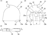
図1は、本実施形態のコンクリートカッターを構成するブレードカバー21の外観形状を示す図であり、図1(1)は正面図、図1(2)は背面図、図1(3)は平面図である。また、図2は、図1(3)に示すX−X線によるブレードカバー21の垂直断面図である。尚、このブレードカバー21がコンクリートカッターの本体に装着された場合、図1(1)、図1(3)、図2における右側がコンクリートカッター本体のフロント側となり、左側がリア側となる。また、図1(2)においてはその逆となる。
FIG. 1 is a view showing the external shape of a
ブレードカバー21は、これらの図に示すように、ケーシング22と、キャスター23(フロント側のキャスター23a、リア側のキャスター23b)と、ダストガイド24と、左右一対のスライダ25,25と、ストッパ26,26とによって構成されている。
As shown in these drawings, the
ケーシング22は、金属製の薄板を加工することにより、コンクリートカッターのブレードを全体的に覆うことができる大きさに形成されており、切削作業時にブレード周りにおいて生じる粉塵の飛散を防止できるように、基本的には外方に対して閉塞された空間を形成する箱形の構成となっているが、底面側は開放されているほか、背面22a(図1(2)参照)には、ブレード周りに装着する際にブレードの回転軸を受け入れるための切欠27が、下縁から上方へ向かって(ケーシング22の中央部付近まで)形成されている。
The
また、ケーシング22の上部には、ダストパイプ(図示せず)を取り付けることができるコネクタ28が装着されている。このコネクタ28は、ケーシング22内において円弧状に形成されたダスト流路29を介してケーシング22内空間と連通した状態となっており、このコネクタ28と集塵装置(図示せず)とをダストパイプによって接続することにより、ケーシング22内において生じた粉塵を、ダスト流路29、及び、ダストパイプを介して集塵装置へ向かって流下させ、回収できるように構成されている。
A
キャスター23a,23bは、ブレードカバー21をブレード周りに装着した場合に、ブレードと干渉しない位置(ブレードカバー21の下部の前端と後端)においてそれぞれ回転自在なように取り付けられている。
The
ダストガイド24は、切削作業時においてブレードチップの接線方向へ噴出する粉塵が、ブレードカバー21の下縁と切削対象面との間の僅かな隙間から、ブレードカバー21の外側へ飛び出してしまうことを防止するためのものであり、底面部及び二枚の側面部からなる第1ダストガイド24aと、第2ダストガイド24bとによって構成されている。
In the
第1ダストガイド24aは、二枚の側面部がそれぞれブレードカバー21の両側面に沿った位置に、また、底面部が、ブレードカバー21の底面の一部を下方から覆うような位置に取り付けられている。第2ダストガイド24bは、ブレードカバー21の一方側の内側面から反対側の内側面まで達する幅寸法を有し、可撓性を有する金属板によって構成されており、ダスト流路29の下端に取り付けられている。
The first dust guide 24a is attached so that the two side surfaces thereof are respectively positioned along the both side surfaces of the
二枚の側面部のフロント側の各端部は、フロント側のキャスター23aのシャフトに枢着されており、第1ダストガイド24aは、所定角度範囲内で、キャスター23aと同軸的に(フロント側を基点としてリア側が)回動可能なようになっている。但し、第1ダストガイド24aは、ダスト流路29の下端に取り付けられている第2ダストガイド24bによって、リア側が下方へ付勢されている。また、第1ダストガイド24aの底面部には、ブレードの進入を受け入れるための切欠溝が形成されている。
The front end portions of the two side portions are pivotally attached to the shaft of the
スライダ25,25は、厚さ3.2mmの金属製の板材を、図1(2)に示すような形状に加工してなるものである。スライダ25,25は、所定の長さの直線状部25aをそれぞれ有しており、これらの直線状部25a,25aがいずれも内側(切欠27側)となる向きで、切欠27を間に挟んで左右方向へ相互に対向するような位置関係をもって、ケーシング22の背面22aに対して取り付けられている。また、これらのスライダ25,25は、直線状部25a,25aが平行となる角度、かつ、ブレードカバー21を水平面上に載置した場合において、直線状部25a,25aが垂直±15°の範囲の角度となるように取り付けられている。
The
更に、スライダ25,25は、図3(図1(2)に示すY−Y線によるブレードカバー21の水平断面の斜視図)に示すように、ケーシング22の背面22aから外側へ一定の間隔をおいた位置に固定されている。つまり、スライダ25,25とケーシング22の背面22aとの間には、大きさが一定(本実施形態においては4.5mm)の間隙Cが形成されている。尚、本実施形態においては、ケーシング22の背面22aとスライダ25,25との間に間隙Cが形成されるように、ケーシング22の背面22aからの突出寸法が等しい複数個(一つのスライダ25につき三個)のゴムブッシュ30(防振材)を介して、スライダ25,25がケーシング22に対してそれぞれ固定されている。
Furthermore, as shown in FIG. 3 (a perspective view of the horizontal cross section of the
より具体的には、ケーシング22の背面22aにおける所定の位置(一つのスライダ25につき三箇所)に貫通孔が形成されており、まず、これらの貫通孔内にそれぞれゴムブッシュ30(中心軸線を通る断面が、図3に示すような形状となるリング状のゴムブッシュ)を嵌め込み、これらのゴムブッシュ30の中央の孔に、一対の締結固定具31(インサートカラー31a及び皿ネジ31b)を装着することにより(ケーシング22の内側からインサートカラー31aを挿通し、スライダ25の外側から、皿ネジ31bを、スライダ25の貫通孔を通してインサートカラー31aの中央の孔にねじ入れることにより)、スライダ25,25をケーシング22に対して取り付けてある。
More specifically, through holes are formed at predetermined positions (three locations per slider 25) on the
ここで使用されるゴムブッシュ30は、いずれも同大、同形状であり、背面22aに形成した貫通孔に装着すると、背面22aから外側へ向かって突出する寸法がいずれも等しくなる。従って、これらのゴムブッシュ30を介して固定されたスライダ25,25と背面22aとの間に形成される間隙Cは、背面22aの突出寸法と等しくなり、一定となる。このように、スライダ25,25は、防振機能を有するゴムブッシュ30を介してケーシング22に対して固定されているため、ブレードカバー21をコンクリートカッターの本体に取り付けた場合に、本体側(原動機やブレード等)からブレードカバー21に伝達される振動を好適に減衰することができる。
The
尚、本実施形態においては、上述の通り、スライダ25,25の全体がケーシング22から離れた位置に固定されているが、必ずしもスライダ25,25の全体がケーシング22から離れている必要はなく、直線状部25a,25aを含む一定の範囲の部分が、ケーシング22の背面22aから外側へ離れた位置に固定され、両者間に一定の間隔(後述するスライドガイドのフラップを間に挟み込むことができる大きさの間隔)が形成されていればよい。但し、この場合には、本体側から伝達される振動の減衰効果は、それほど期待することができない。
In the present embodiment, as described above, the
ストッパ26,26は、所定の厚さ寸法を有する金属板を、背面22aに溶接固定してなるものであって、スライダ25,25の上部と切欠27との間の位置に配置されている。
The
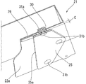
図4は、本発明のコンクリートカッターを構成するスライドガイド32,32の外観形状を示す図である。尚、図4(1)は、スライドガイド32,32が機体フレーム2のフロント部2aの左側面(機体フレーム2のフロント側からリア側に向かって左側となる側面)に取り付けられた状態を、機体フレーム2の左側方の視点から見た状態を示す図であり、図4(2)はその斜視図である。スライドガイド32,32は、図1〜図3に示したブレードカバー21を、機体フレーム2に対し、上下方向へ移動可能な状態で、かつ、回転軸6を中心として回動可能なように保持させるためのものである。
FIG. 4 is a view showing the external shape of the slide guides 32, 32 constituting the concrete cutter of the present invention. 4 (1) shows a state in which the slide guides 32, 32 are attached to the left side surface of the
これらの図に示すように、スライドガイド32,32は、機体フレーム2のフロント部2aの側面(左側面)の下方に取り付けられている。尚、フロント部2aの側面からは、ブレード(図示せず)を軸支する回転軸6が突出しており、スライドガイド32,32は、この回転軸6を間に挟んで機体フレーム2の前後方向へ相互に対向するような位置関係をもって配置されている。
As shown in these drawings, the slide guides 32 and 32 are attached below the side surface (left side surface) of the
これらのスライドガイド32,32は、それぞれベース33と、フラップ34とによって構成され、各ベース33は、それぞれ円弧状部33aを有している。円弧状部33aは、ベース33の一つの側面が、回転軸6を中心とする円弧状に湾曲してなるものであり、回転軸6の突出方向へ所定の厚さ(本実施形態においては4.5mm)を有している。尚、二つの円弧状部33a,33aは、回転軸6を中心とする一つの仮想円R(図4(1)参照)に沿って湾曲しており、ブレードカバー21に取り付けられているスライダ25,25の直線状部25a,25a間の離間寸法F(図1(2)参照)は、この仮想円Rの直径とほぼ等しい寸法に設定されている。
These slide guides 32 and 32 are each constituted by a
フラップ34は、円弧状部33aの厚さ分だけ機体フレーム2(フロント部2aの側面)から側方へ一定の間隔をおいた位置に形成されており、円弧状部33aの外側の縁部から、円弧状部33aの半径方向外側へ突出した状態となっている。つまり、フラップ34とフロント部2aの側面との間には、大きさが一定(本実施形態においては4.5mm)の間隙Dが形成されている。
The
機体フレーム2に対して、ブレードカバー21(図1〜図3参照)を取り付ける場合、図1(2)及び図3に示すスライダ25,25の直線状部25a,25aを、それぞれ下端側から、図4(2)に示すスライドガイド32,32の間隙D(フラップ34とフロント部2aの側面との間の間隙)内に進入させる。そうすると、スライダ25,25の直線状部25a,25aが、フラップ34,34とフロント部2aの側面とによって挟持される。その結果、機体フレーム2の側方(回転軸6の突出方向)へのブレードカバー21の移動が規制されることになる。
When the blade cover 21 (see FIGS. 1 to 3) is attached to the
また、スライダ25,25の直線状部25a,25a間の離間寸法F(図1(2)参照)は、上述の通り、スライドガイド32,32の円弧状部33a,33aと軌を同じくする仮想円R(図4(1)参照)の直径とほぼ等しい寸法に設定されているため、スライダ25,25の直線状部25a,25aをそれぞれ、下縁側からスライドガイド32,32のフラップ34とフロント部2aの側面との間に進入させると、円弧状部33a,33aが、二つの直線状部25a,25aによって挟持された状態となり、機体フレーム2の前後方向へのブレードカバー21の移動が規制されるとともに、ブレードカバー21は、回転軸6を中心とする所定角度範囲内で、円弧状部33a,33a周りに回動可能な状態となっている。
Further, as described above, the separation dimension F (see FIG. 1B) between the
そして、スライダ25,25は、上述の通り、直線状部25a,25aが平行になっており、直線状部25a,25a間の離間寸法F(図1(2)参照)は一定であるので、ブレードカバー21は、スライドガイド32,32及び機体フレームに対し、上下方向へ摺動可能な状態となっている。
And as above-mentioned, the
図5は、機体フレーム2に取り付けられた状態のブレードカバー21の垂直断面図である。尚、この図では、ブレードカバー21の背面に取り付けられているスライダ25,25、及び、ストッパ26,26については破線で表示し、機体フレーム2のフロント部2aの側面に取り付けられているスライドガイド32,32、及び、回転軸6によって軸支されているブレード5については、一点鎖線で表示している。また、スライドガイド32,32のベース33,33については、他の要素との境界を明確にすべく斜線を表示している。
FIG. 5 is a vertical sectional view of the
図5に示すように、機体フレーム2が後方側へ傾斜し、フロント部2aが地面(切削対象面G)から最も高い位置にある状態で、ブレードカバー21を機体フレーム2に取り付けると(スライダ25,25をそれぞれ、下端側から、スライドガイド32,32の間隙D(図4(2)参照)内に進入させると)、ブレードカバー21は重力により下方へ摺動し、相対的に、スライドガイド32,32は、スライダ25,25間の領域のうち、上方の領域(スライダ25,25の上部付近の領域)へ向かって摺動する。
As shown in FIG. 5, when the
但し、スライダ25,25の上部と切欠27との間には、ブレードカバー21の下方への移動(スライダ25,25間の領域におけるスライドガイド32,32の上方への移動)を、ある高さ位置(ブレードカバー21がブレード5に接触しない位置)において規制するストッパ26,26が配置されており、スライドガイド32,32がストッパ26,26に当接すると、ブレードカバー21は、それ以上は下降せず、図5に示すような姿勢で機体フレーム2の側方において保持されることになる。
However, between the upper portions of the
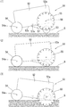
本実施形態のコンクリートカッターを用いて、道路の舗装面等(切削対象面G)に対して切削作業を行う場合、図示しない切削深さ調整ハンドルを操作することにより、図5に示すような状態から、機体フレーム2の傾斜角度を次第に小さくしていき、フロント部2aを切削対象面Gに近づけていく。そうすると、ある時点で、図6に示すように、ブレードカバー21のキャスター23a,23bが切削対象面Gに接触する。
When performing a cutting operation on a road pavement surface or the like (surface to be cut G) using the concrete cutter of this embodiment, a state as shown in FIG. 5 is obtained by operating a cutting depth adjustment handle (not shown). Therefore, the inclination angle of the
図5に示す状態から図6に示す状態に至る間は、スライドガイド32,32がストッパ26,26に当接した状態で、ブレードカバー21は、機体フレーム2から吊り下げられたような状態となっているが、図6に示す位置(切削直前位置)から更に、フロント部2aを切削対象面Gに近づけていくと、スライドガイド32,32がストッパ26,26から離れ、スライダ25,25間を、下方へ移動(摺動)していくことになる。
During the period from the state shown in FIG. 5 to the state shown in FIG. 6, the
そして、ブレード5が所定方向(ブレード5の下縁側が、機体フレーム2のリア側からフロント側へ移動する方向、図5及び図6において反時計回り方向)へ高速回転している状態で、ブレード5の下縁が切削対象面Gと接触すると切削が開始され、最終的には、図7に示す深さ位置(切削最深位置)まで切削することができる。
The
尚、図6の切削直前位置から、図7の切削最深位置までに移行する間、機体フレーム2は、図示しない後輪を中心として回動する(より具体的には、フロント部2aが、切削対象面Gよりもブレード5の突出高さ分だけ高い位置から、切削対象面Gに近接した位置まで回動する)ことになるが、このとき、ブレードカバー21を保持するスライドガイド32の傾斜角度も変更されることになる。
During the transition from the position immediately before cutting in FIG. 6 to the deepest cutting position in FIG. 7, the
但し、ブレードカバー21は、回転軸6を中心として、スライドガイド32,32の円弧状部33a,33a周りに回動可能な状態で保持されているため、機体フレーム2及びスライドガイド32,32の傾斜角度が変更された場合でも、水平な状態(フロント側のキャスター23a、及び、リア側のキャスター23bがいずれも切削対象面Gに接地し、ブレードカバー21の下縁が切削対象面Gと平行な状態)が維持される。
However, since the
従って、機体フレームの傾斜角度の変更に伴って、ブレードカバーの下縁と切削対象面との間に大きな隙間が形成されてしまうというような、従来技術における問題を好適に回避することができ、切削作業によって生じる粉塵の飛散を防止するとともに、それらの粉塵を集塵装置によって好適に吸引し、回収することができる。 Therefore, with the change in the inclination angle of the machine body frame, it is possible to suitably avoid problems in the prior art such that a large gap is formed between the lower edge of the blade cover and the surface to be cut, While preventing the scattering of the dust which arises by cutting operation, those dusts can be suitably attracted | sucked and collect | recovered with a dust collector.
また、枢着部やリンク機構を介在させることなく、極めてシンプルな要素のみによって、機体フレーム2に対するブレードカバー21の回動と、上下方向への移動を実現できるため、振動に対しても十分な耐久性を期待することができるほか、給脂が不要であり、更に、給脂に伴う粉塵の付着も回避できるので、煩雑なメンテナンス作業を省略できるという効果を期待することができる。
In addition, the rotation of the
更に、本実施形態のブレードカバー21は、図2に示すように、上半部が半円形に形成されるとともに、ダスト流路29の始端部が、切削作業時に生じる粉塵の噴出方向(切削対象面付近におけるブレードの接線方向)に沿って開口しているため、集塵装置によってブレードカバー21内の空気を吸引すると、ブレードカバー21内において旋回流が生じ、ブレードカバー21内の粉塵を極めて円滑に、かつ、効率よく吸引し、回収することができる。
Further, as shown in FIG. 2, the
また、本実施形態においては、切削作業時に切削対象面から粉塵が噴出する位置に、リア側が下方へ付勢されたダストガイド24が配置されており、切削作業時においては、ダストガイド24の底面部のリア側が、常に切削対象面に接地した状態となるため、特に切削初期において、ブレードカバー21の下縁と切削対象面との間の僅かな隙間から、粉塵がブレードカバー21の外側へ飛び出してしまうことを好適に防止することができ、高い精度で粉塵を回収することができる。
Further, in the present embodiment, the
尚、本実施形態においては、左右一対の円弧状部33a,33aが、物理的に独立した二つのスライドガイド32,32にそれぞれ一つずつ形成されているが、スライドガイド32を単一の要素として構成し(例えば、馬蹄形に構成し)、その一つのスライドガイド32において、ブレードカバー21を回動可能なように保持する左右一対の円弧状部33a,33aを形成するようにしてもよい。
In the present embodiment, a pair of left and right arc-shaped
また、左右一対の直線状部25a,25aについても、本実施形態においては、物理的に独立した二つのスライダ25,25にそれぞれ一つずつ形成されているが、スライダ25を単一の要素として構成し、その一つのスライダ25において、円弧状部33aを挟持する左右一対の直線状部25a,25aを形成するようにしてもよい。
Also, in the present embodiment, the pair of left and right
更に、ストッパ26,26は、スライダ25とは別個の独立した要素として構成されているが、スライダ25,25の一部に、ストッパ26として機能する部分を形成することもできる。例えば、直線状部25aの上端部から、内側へ向かって突出する突起を形成してもよいし、また、左右一対の直線状部25a,25a同士を、上端部において連結するようにしてもよい。
Furthermore, although the
2:機体フレーム、
2a:フロント部、
5:ブレード、
6:回転軸、
21:ブレードカバー、
22:ケーシング、
22a:背面、
23,23a,23b:キャスター、
24:ダストガイド、
24a:第1ダストガイド、
24b:第2ダストガイド、
25:スライダ、
25a:直線状部、
26:ストッパ、
27:切欠、
28:コネクタ、
29:ダスト流路、
30:ゴムブッシュ、
31:締結固定具、
31a:インサートカラー、
31b:皿ネジ、
32:スライドガイド、
33:ベース、
33a:円弧状部、
34:フラップ、
51:コンクリートカッター、
52:機体フレーム、
52a:フロント部、
52b:底面、
53:前輪、
54:後輪、
54a:シャフト、
55:ブレード、
56:回転軸、
57:支持アーム、
57a:基端部、
C,D:間隙、
G:切削対象面、
R:仮想円
2: Airframe frame,
2a: Front part,
5: Blade,
6: Rotating shaft
21: Blade cover,
22: casing,
22a: back side,
23, 23a, 23b: casters,
24: dust guide,
24a: first dust guide,
24b: second dust guide,
25: slider,
25a: linear portion,
26: Stopper,
27: Notch,
28: Connector,
29: dust channel,
30: Rubber bush,
31: Fastening fixture,
31a: Insert color,
31b: countersunk screw
32: Slide guide,
33: Base,
33a: arc-shaped part,
34: Flap
51: Concrete cutter,
52: Airframe frame,
52a: front part,
52b: bottom surface,
53: Front wheel,
54: Rear wheel
54a: shaft,
55: Blade,
56: Rotating shaft,
57: Support arm,
57a: proximal end,
C, D: gap,
G: surface to be cut,
R: Virtual circle
Claims (6)
本体は、機体フレームと、車輪と、原動機と、ブレードとからなり、機体フレームの前後方向の傾斜角度、及び、機体フレームのフロント部の高さを変更することにより、切削作業時におけるブレードの切削深さを調整できるように構成され、
ブレードカバーは、ブレードを全体的に覆うことができる大きさに形成された箱形のケーシングと、ケーシングの背面に取り付けられたスライダとからなり、
ケーシングは、底面側が開放され、背面に、ブレードの回転軸を受け入れるための切欠が、下縁から上方へ向かって所定の高さ位置まで形成され、
スライダは、所定の長さの左右一対の直線状部を有し、これらの直線状部がいずれも内側となる向きで、かつ、平行となるように、また、少なくとも直線状部を含む一定の範囲の部分と、ケーシングの背面との間に一定の間隔が形成されるように取り付けられ、
スライドガイドは、左右一対の円弧状部と、スライダの直線状部を挟持するためのフラップとからなり、
左右一対の円弧状部は、ブレードを軸支する回転軸を間に挟んで機体フレームの前後方向へ相互に対向する位置関係をもって機体フレームの側面に配置され、
フラップは、機体フレームの側面との間に一定の間隙が形成されるように取り付けられ、
スライダの直線状部を、スライドガイドのフラップと機体フレームとの間に挟持させるとともに、左右一対の直線状部の間に円弧状部を挟持させることにより、ブレードカバーが、スライドガイド及び機体フレームに対し、上下方向へ摺動可能な状態で、かつ、円弧状部周りに回動可能な状態で保持されていることを特徴とするコンクリート等の切削装置。 Consists of a main body, a blade cover, and a slide guide,
The main body consists of a fuselage frame, wheels, a prime mover, and a blade. By changing the tilt angle in the front-rear direction of the fuselage frame and the height of the front part of the fuselage frame, cutting of the blade during cutting work It is configured so that the depth can be adjusted,
The blade cover consists of a box-shaped casing formed in a size that can cover the entire blade, and a slider attached to the back of the casing,
The casing is open on the bottom side, and a notch for receiving the rotating shaft of the blade is formed on the back surface from the lower edge to a predetermined height position.
The slider has a pair of left and right linear portions of a predetermined length, and the linear portions are oriented in parallel and parallel to each other, and include at least a linear portion. It is attached so that a certain distance is formed between the part of the range and the back of the casing,
The slide guide is composed of a pair of left and right arc-shaped portions and a flap for sandwiching the linear portion of the slider.
The pair of left and right arc-shaped portions are arranged on the side surface of the body frame with a positional relationship facing each other in the front-rear direction of the body frame with a rotating shaft pivotally supporting the blade interposed therebetween,
The flap is attached so that a certain gap is formed between the sides of the fuselage frame,
The blade cover is attached to the slide guide and the machine frame by holding the linear part of the slider between the flap of the slide guide and the fuselage frame, and holding the arcuate part between the pair of left and right linear parts. On the other hand, a cutting device for concrete or the like, which is held in a state in which it can slide in the vertical direction and in a state in which it can rotate around an arcuate portion.
Priority Applications (3)
| Application Number | Priority Date | Filing Date | Title |
|---|---|---|---|
| JP2011025027A JP5215420B2 (en) | 2011-02-08 | 2011-02-08 | Concrete cutting equipment |
| FR1250924A FR2971186B1 (en) | 2011-02-08 | 2012-02-01 | CUTTING APPARATUS FOR CONCRETE OR THE LIKE |
| US13/365,681 US8740311B2 (en) | 2011-02-08 | 2012-02-03 | Cutting apparatus for concrete or the like |
Applications Claiming Priority (1)
| Application Number | Priority Date | Filing Date | Title |
|---|---|---|---|
| JP2011025027A JP5215420B2 (en) | 2011-02-08 | 2011-02-08 | Concrete cutting equipment |
Publications (2)
| Publication Number | Publication Date |
|---|---|
| JP2012162939A JP2012162939A (en) | 2012-08-30 |
| JP5215420B2 true JP5215420B2 (en) | 2013-06-19 |
Family
ID=46547498
Family Applications (1)
| Application Number | Title | Priority Date | Filing Date |
|---|---|---|---|
| JP2011025027A Active JP5215420B2 (en) | 2011-02-08 | 2011-02-08 | Concrete cutting equipment |
Country Status (3)
| Country | Link |
|---|---|
| US (1) | US8740311B2 (en) |
| JP (1) | JP5215420B2 (en) |
| FR (1) | FR2971186B1 (en) |
Families Citing this family (15)
| Publication number | Priority date | Publication date | Assignee | Title |
|---|---|---|---|---|
| ITMO20130017A1 (en) * | 2013-01-28 | 2014-07-29 | Resinchim Societa A Responsabilita Limitata | PERFECT MACHINE FOR CUTTING FLOORS. |
| WO2016038126A1 (en) * | 2014-09-10 | 2016-03-17 | Simex Engineering S.R.L. | Excavating equipment for excavating surfaces, in particular solid surfaces, and operating machine equipped with said excavating equipment |
| CA3082210A1 (en) * | 2016-11-16 | 2018-05-24 | Envirochasing Ip Holdings Pty Ltd | Extraction apparatus |
| US10683634B2 (en) * | 2017-09-22 | 2020-06-16 | Coneqtec Corp. | Debris diverter for microtrenchers |
| CN109016172A (en) * | 2018-09-22 | 2018-12-18 | 中北大学 | A kind of concrete cutting machine |
| EP3659763B1 (en) | 2018-11-28 | 2023-05-31 | Black & Decker Inc. | Power tool |
| CN109468932B (en) * | 2018-12-19 | 2020-10-16 | 石凯 | Joint cutting device for road and bridge |
| CN109778654B (en) * | 2019-03-14 | 2020-11-24 | 黄益艺 | Road surface groover with groove depth adjustment mechanism |
| US11384489B2 (en) | 2019-06-17 | 2022-07-12 | Ariel Gerardo Martinez | Scarifier system, and method of resurfacing or remodeling a ground surface using the scarifier system |
| WO2021107544A1 (en) * | 2019-11-26 | 2021-06-03 | 주식회사 이건 | Floor cutting machine having dust-collecting cover coupled thereto |
| JP7251805B2 (en) * | 2020-09-24 | 2023-04-04 | 三笠産業株式会社 | Lock switching mechanism for rotary operation handle |
| CN112356319B (en) * | 2020-10-28 | 2023-01-17 | 连金玉 | Stone plate cutting machine capable of cutting transversely and longitudinally |
| CN112221829B (en) * | 2020-11-19 | 2021-04-30 | 智海工程设计有限公司 | Multidirectional construction engineering design field marker and use method thereof |
| CN112853886B (en) * | 2021-01-18 | 2022-07-26 | 台州市四方交通建设工程有限公司 | No-drag-mark artistic concrete pavement paving device |
| US11628587B2 (en) * | 2021-02-24 | 2023-04-18 | Techtronic Cordless Gp | Floor saw with blade guard |
Family Cites Families (9)
| Publication number | Priority date | Publication date | Assignee | Title |
|---|---|---|---|---|
| JPS488042U (en) * | 1971-06-09 | 1973-01-29 | ||
| US4041928A (en) * | 1976-04-29 | 1977-08-16 | Norton Company | Masonry saw |
| JPS5499329A (en) * | 1978-01-20 | 1979-08-06 | Nippon Telegraph & Telephone | Blade cover for concrete cutter |
| WO1993002844A1 (en) * | 1991-07-26 | 1993-02-18 | Peter Campbell Pty. Ltd. | Improved blade shaft drive for machines having rotary cutting or abrading tools |
| JP2594185Y2 (en) * | 1992-03-06 | 1999-04-19 | 有限会社カサノ工業 | Cutter equipment |
| JPH072512U (en) * | 1993-06-14 | 1995-01-13 | ラサ工業株式会社 | Dry cutter device |
| JPH081655A (en) * | 1994-06-24 | 1996-01-09 | Nakayama Tekko Kk | Blade cover in cutting device for concrete or the like |
| US7114494B2 (en) * | 1999-09-17 | 2006-10-03 | Husqvarna Professional Outdoor Products Inc. | Fluid pickup assembly and blade guard for a pavement treatment apparatus |
| WO2006101423A1 (en) * | 2005-03-23 | 2006-09-28 | Husqvarna Ab | Improvements relating to a cutting or sawing machine |
-
2011
- 2011-02-08 JP JP2011025027A patent/JP5215420B2/en active Active
-
2012
- 2012-02-01 FR FR1250924A patent/FR2971186B1/en active Active
- 2012-02-03 US US13/365,681 patent/US8740311B2/en active Active
Also Published As
| Publication number | Publication date |
|---|---|
| FR2971186A1 (en) | 2012-08-10 |
| US8740311B2 (en) | 2014-06-03 |
| FR2971186B1 (en) | 2016-05-13 |
| US20120200140A1 (en) | 2012-08-09 |
| JP2012162939A (en) | 2012-08-30 |
Similar Documents
| Publication | Publication Date | Title |
|---|---|---|
| JP5215420B2 (en) | Concrete cutting equipment | |
| US8764356B2 (en) | Dust collecting case and cutting machine equipped therewith | |
| US7789003B2 (en) | Miter saw | |
| JP4248766B2 (en) | Reciprocating cutting tool | |
| RU2471612C2 (en) | Cutting devices | |
| EP0958878A2 (en) | Dust collector for a power tool | |
| TW201325772A (en) | Glide movement controller and power miter saw including such controller | |
| JP2007038645A (en) | Dust collection cover and cutter equipped with the same | |
| JP2009023004A (en) | Portable cutter | |
| US5653218A (en) | Electric-powered stone cutter | |
| CN101018479A (en) | Floating attachement linkage | |
| CN111843708A (en) | Plastics polisher of plastic products processing | |
| JP2014042988A (en) | Cutting machine | |
| WO2019109982A1 (en) | Lawn mower | |
| CN101835573A (en) | Saw with circular blade | |
| TW201341089A (en) | Power cord routing system for miter saw with hinge linkage linear guide | |
| JP2015062402A (en) | Riding mower | |
| JP7057932B2 (en) | Mower mowing part structure | |
| JP6088914B2 (en) | Walking mower | |
| JP2013048614A (en) | Clipping collecting-discharging device | |
| WO2014019066A1 (en) | Assembly to operate a reciprocating saw blade from a rotating shaft | |
| JPH0347708A (en) | Wet concrete cutter | |
| JP2020156446A (en) | Lawn mower | |
| JP2006002262A (en) | Cleaning system of spinning nozzle and method for cleaning spinning machine | |
| JPH0732574Y2 (en) | Muddy water discharge device for wet concrete cutter device |
Legal Events
| Date | Code | Title | Description |
|---|---|---|---|
| A621 | Written request for application examination |
Free format text: JAPANESE INTERMEDIATE CODE: A621 Effective date: 20120910 |
|
| A977 | Report on retrieval |
Free format text: JAPANESE INTERMEDIATE CODE: A971007 Effective date: 20130128 |
|
| TRDD | Decision of grant or rejection written | ||
| A01 | Written decision to grant a patent or to grant a registration (utility model) |
Free format text: JAPANESE INTERMEDIATE CODE: A01 Effective date: 20130205 |
|
| A61 | First payment of annual fees (during grant procedure) |
Free format text: JAPANESE INTERMEDIATE CODE: A61 Effective date: 20130228 |
|
| R150 | Certificate of patent or registration of utility model |
Ref document number: 5215420 Country of ref document: JP Free format text: JAPANESE INTERMEDIATE CODE: R150 Free format text: JAPANESE INTERMEDIATE CODE: R150 |
|
| FPAY | Renewal fee payment (event date is renewal date of database) |
Free format text: PAYMENT UNTIL: 20160308 Year of fee payment: 3 |
|
| R250 | Receipt of annual fees |
Free format text: JAPANESE INTERMEDIATE CODE: R250 |
|
| R250 | Receipt of annual fees |
Free format text: JAPANESE INTERMEDIATE CODE: R250 |
|
| S531 | Written request for registration of change of domicile |
Free format text: JAPANESE INTERMEDIATE CODE: R313532 |
|
| R350 | Written notification of registration of transfer |
Free format text: JAPANESE INTERMEDIATE CODE: R350 |
|
| R250 | Receipt of annual fees |
Free format text: JAPANESE INTERMEDIATE CODE: R250 |
|
| R250 | Receipt of annual fees |
Free format text: JAPANESE INTERMEDIATE CODE: R250 |
|
| R250 | Receipt of annual fees |
Free format text: JAPANESE INTERMEDIATE CODE: R250 |