EP3658847B1 - Projectile cartridge and method for producing a projectile cartridge - Google Patents
Projectile cartridge and method for producing a projectile cartridge Download PDFInfo
- Publication number
- EP3658847B1 EP3658847B1 EP17725508.0A EP17725508A EP3658847B1 EP 3658847 B1 EP3658847 B1 EP 3658847B1 EP 17725508 A EP17725508 A EP 17725508A EP 3658847 B1 EP3658847 B1 EP 3658847B1
- Authority
- EP
- European Patent Office
- Prior art keywords
- projectile
- layer
- case
- cartridge
- additive
- Prior art date
- Legal status (The legal status is an assumption and is not a legal conclusion. Google has not performed a legal analysis and makes no representation as to the accuracy of the status listed.)
- Active
Links
Images

Classifications
-
- F—MECHANICAL ENGINEERING; LIGHTING; HEATING; WEAPONS; BLASTING
- F42—AMMUNITION; BLASTING
- F42B—EXPLOSIVE CHARGES, e.g. FOR BLASTING, FIREWORKS, AMMUNITION
- F42B5/00—Cartridge ammunition, e.g. separately-loaded propellant charges
- F42B5/02—Cartridges, i.e. cases with charge and missile
- F42B5/067—Mounting or locking missiles in cartridge cases
Definitions
- the invention relates to a projectile cartridge with a projectile and a case and with a seal between the projectile and the case, the seal containing a highly viscous sealing medium, in particular a bitumen mixture, as for example in FIG GB2305994 A described.
- the invention further relates to a method for producing a projectile cartridge with a seal between a projectile and a sleeve, the seal containing a highly viscous sealing medium, in particular a bitumen mixture.
- seals are required which are absolutely tight over a long period of over 10 years in the case of limited negative or positive pressure and in the event of a planned temperature fire.
- the seal between the projectile and the sleeve should be done as inexpensively as possible.
- the seal between the projectile and the case should also ensure high pull-out resistances and be as simple as possible to manufacture in series.
- Sealing means with a highly viscous sealing medium are generally known from the prior art.
- viscous sealing medium with an appropriate thinner is applied to the inside of the sleeve.
- the joining of the projectile into the case pushes part of the applied sealing medium into the case.
- the remaining sealing medium then creates the seal.
- the sealing medium is burned.
- the connection of the projectile and the sleeve by means of the highly viscous sealing medium is force and cohesive.
- a highly viscous sealing medium is very difficult to handle because of its viscosity and lubricates when the projectile is joined to the case.
- a projectile cartridge has become known in which a projectile is sealed with a cartridge case by means of a two-component adhesive.
- the disadvantage of the known bullet cartridges and their manufacture is that the attraction forces should be greater than 400 N if possible.
- the materials measurement and copper alloys used in particular for the sleeve are not good bonding partners for synthetic adhesives. Therefore, only low tightening forces are possible through the use of the known acrylate adhesives and two-component adhesives. When using synthetic adhesives, the tightening force is only generated by the force-fit connection between the projectile and the case.
- the invention is based on the problem of developing a projectile cartridge of the type mentioned at the outset in such a way that it enables high pull-out resistances with a small scatter. Furthermore, a method for the production of the projectile cartridge is to be created which enables high pull-out resistances with a small scatter.
- the first-mentioned problem is solved according to the invention in that the seal has two layers of a highly viscous sealing medium, in particular a bitumen mixture, a first layer of a highly viscous sealing medium, in particular a bitumen mixture, with an additive to increase the sliding properties of the highly viscous sealing medium, in particular a bitumen mixture, and a second layer contains no or a lower proportion of additive than the first layer.
- the second layer ensures the sealing performance of the bullet cartridge.
- the first layer protects the second layer from shearing off when the projectile is joined to the case.
- the projectile cartridge is therefore particularly tightly sealed. Since the adhesive properties of the highly viscous sealing medium on the material of the sleeve are significantly higher than with the acrylate adhesive according to the prior art, the projectile is also held in a materially bonded manner.
- the second layer creates a uniform first layer with the additive, which keeps the spread of the pull-out resistances and the speed ranges of the bullet cartridge particularly low.
- the highly viscous sealing medium is preferably mixed with a suitable thinner.
- the bullet cartridge can be manufactured particularly inexpensively if the highly viscous sealing medium is a bitumen mixture.
- shearing of the first layer when joining the projectile into the case can be avoided if the two layers are sandwiched on top of each other and when the first layer faces the projectile and the second layer faces the case.
- the additive contains graphite.
- graphite as an additive is particularly inexpensive and easy to process.
- Graphite is also resistant to high temperatures and is retained even if the bitumen is burned when it is fired. This improves the sliding properties when firing.
- a particularly small spread of the pull-out resistances can easily be ensured if the mixing ratio of bitumen to graphite in the first layer corresponds to 2.5 to 3.
- This choice of material means that the bitumen is burned when it is fired and the graphite remains and creates a high-temperature-resistant sliding layer.
- the first layer can preferably also be used as an additive.
- the sealing media are particularly advantageous. According to another advantageous development of the invention, high pull-out resistances with small scatter are achieved if the first layer contains 48-35% by weight bitumen, 8-25% by weight graphite and the remainder thinner and / or if the second layer contains 55-75% by weight of bitumen and 45-25% by weight of thinner.
- the second problem namely the creation of a method for producing the bullet cartridge, which enables high pull-out resistances with low scattering, is solved according to the invention in that two layers of bitumen are applied one behind the other before joining the projectile to the case on the projectile or the case, wherein the layer closest to the opposite component of the projectile or the sleeve has an additive to increase the sliding properties of the bitumen.
- This design creates two layers between the projectile and the case, one layer contributing to the creation of a high level of tightness and the layer provided with the additive ensuring a low spread of the pull-out resistance.
- smearing of the layers can easily be avoided if the two layers are applied to the inside of the sleeve, with a first layer located closer to the edge of the sleeve not containing the additive and a second layer located deeper in the sleeve or contains a lower proportion of additive than the first layer.
- the first layer provided with the additive is pressed against the other second layer.
- the first layer provided with the additive is smoothed out and thus creates a particularly homogeneous layer.
- Figure 1 shows a projectile 1 and a case 2 before being joined to one in Figure 3 projectile cartridge 3 shown.
- the sleeve 2 is shown in a longitudinal section.
- Two layers 4, 5 are applied to the inside of the sleeve 2.
- a first layer 4 arranged closer to the free edge of the sleeve 2 contains bitumen mixed with an additive.
- a second layer 5 located deeper in the sleeve 2 contains bitumen without an additive.
- the layers 4, 5 can be created in one operation with a suitable tool, preferably by means of spray technology.
- the first layer 4 has 42% by weight bitumen, 42% by weight thinner and 16% by weight graphite. For the width of the first layer 4 of approximately 1 mm, an amount of approximately 0.7 mg is sufficient.
- the second layer 5 contains 66% by weight of bitumen and 34% by weight of thinner. For the width of the second layer 5 of 3 mm, the amount used is approximately 0.8 mg.
- the distance between the two layers 4, 5 is less than 1.5 mm.
- Figure 2 shows the projectile 1 and the case 2 from Figure 1 during joining. It can be seen here that the first layer 4 provided with additive is pressed against the second layer 5. The second layer 5 prevents the additive-provided first layer 4 from being pushed in.
- Figure 3 shows the projectile cartridge 3 produced with the method in a highly schematic manner. It can be seen here that the two layers 4, 5 create a seal 6 of the projectile 1 with respect to the case 2.
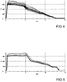
- Figure 4 shows a force-expansion diagram of pull-out resistances of several projectile cartridges 3.
- the spread of the pull-out resistances of different projectile cartridges is particularly small.
- the projectile cartridges 3 according to the invention have an initial pull-out resistance of over 600N.
- Figure 5 shows a force-expansion diagram of pull-out resistances of several projectile cartridges, which according to the state of the art only have a non-positive connection of the projectile 1 with the case 2.
- the comparison of the Figures 4 and 5 shows that the course of the purely frictional connection according to Figure 5 is noticeably more uneven over the stretch.
- the initial pull-out resistance in the purely frictional connection is only half of the pull-out resistance of the bullet cartridge 3 according to the invention.
Landscapes
- Engineering & Computer Science (AREA)
- General Engineering & Computer Science (AREA)
- Aiming, Guidance, Guns With A Light Source, Armor, Camouflage, And Targets (AREA)
- Sealing Material Composition (AREA)
- Continuous Casting (AREA)
Description
Die Erfindung betrifft eine Geschosspatrone mit einem Projektil und einer Hülse und mit einer Abdichtung zwischen Projektil und Hülse, wobei die Abdichtung ein hochviskoses Dichtmedium, insbesondere Bitumengemisch, enthält, wie zum Beispiel in
Insbesondere bei Klein- und Mittelkaliber sind Abdichtungen erforderlich, welche bei begrenzten Unter-oder Überdruck und in einem vorgesehenen Temperaturbrand über eine lange Zeitdauer von über 10 Jahren absolut dicht sind. Die Abdichtung zwischen Projektil und Hülse soll dabei möglichst kostengünstig geschehen. Die Abdichtung zwischen Projektil und Hülse soll zudem hohe Auszugswiderstände gewährleisten, und möglichst einfach in Serie herstellbar sein.Particularly in the case of small and medium calibers, seals are required which are absolutely tight over a long period of over 10 years in the case of limited negative or positive pressure and in the event of a planned temperature fire. The seal between the projectile and the sleeve should be done as inexpensively as possible. The seal between the projectile and the case should also ensure high pull-out resistances and be as simple as possible to manufacture in series.
Dichtmittel mit einem hochviskosen Dichtmedium sind aus dem Stand der Technik allgemein bekannt. Hierbei wird zähflüssiges Dichtmedium mit einem dazugehörigen Verdünner auf die Innenseite der Hülse aufgetragen. Das Fügen des Projektils in die Hülse drückt einen Teil des aufgetragenen Dichtmediums in die Hülse. Das restliche Dichtmedium erzeugt dann die Abdichtung. Beim Abschuss des Projektils wird das Dichtmedium verbrannt. Die Verbindung des Projektils und der Hülse mittels des hochviskosen Dichtmediums erfolgt kraft- und stoffschlüssig. Jedoch ist ein hochviskoses Dichtmedium wegen seiner Zähflüssigkeit sehr problematisch zu handhaben und schmiert beim Fügen des Projektils mit der Hülse.Sealing means with a highly viscous sealing medium are generally known from the prior art. In this case, viscous sealing medium with an appropriate thinner is applied to the inside of the sleeve. The joining of the projectile into the case pushes part of the applied sealing medium into the case. The remaining sealing medium then creates the seal. When the projectile is fired, the sealing medium is burned. The connection of the projectile and the sleeve by means of the highly viscous sealing medium is force and cohesive. However, a highly viscous sealing medium is very difficult to handle because of its viscosity and lubricates when the projectile is joined to the case.
Aus der
Aus der
Nachteilig bei den bekannten Geschosspatronen und deren Herstellung ist, dass die Anzugskräfte möglichst größer 400 N sein sollen. Die insbesondere für die Hülse verwendeten Materialien Messung und Kupferlegierungen stellen jedoch keinen guten Klebepartner für synthetische Klebstoffe dar. Daher sind durch Einsatz der bekannten Acrylatkleber und Zweikomponentenkleber nur geringe Anzugskräfte möglich. Die Anzugskraft wird beim Einsatz der synthetischen Klebstoffe nur von der kraftschlüssigen Verbindung zwischen Projektil und Hülse erzeugt.The disadvantage of the known bullet cartridges and their manufacture is that the attraction forces should be greater than 400 N if possible. The materials measurement and copper alloys used in particular for the sleeve, however, are not good bonding partners for synthetic adhesives. Therefore, only low tightening forces are possible through the use of the known acrylate adhesives and two-component adhesives. When using synthetic adhesives, the tightening force is only generated by the force-fit connection between the projectile and the case.
Der Erfindung liegt das Problem zugrunde, eine Geschosspatrone der eingangs genannten Art so weiter zu bilden, dass sie hohe Auszugswiderstände bei kleiner Streuung ermöglicht. Weiterhin soll ein Verfahren zur Herstellung der Geschosspatrone geschaffen werden, welches hohe Auszugswiderstände bei kleiner Streuung ermöglicht.The invention is based on the problem of developing a projectile cartridge of the type mentioned at the outset in such a way that it enables high pull-out resistances with a small scatter. Furthermore, a method for the production of the projectile cartridge is to be created which enables high pull-out resistances with a small scatter.
Das erstgenannte Problem wird erfindungsgemäß dadurch gelöst, dass die Abdichtung zwei Schichten aus einem hochviskosem Dichtmedium, insbesondere Bitumengemisch, aufweist, wobei eine erste Schicht ein hochviskoses Dichtmedium, insbesondere Bitumengemisch, mit einem Additiv zur Erhöhung der Gleiteigenschaften des hochviskosen Dichtmediums, insbesondere Bitumengemisch, und eine zweite Schicht kein oder einen geringeren Anteil an Additiv als die erste Schicht enthält.The first-mentioned problem is solved according to the invention in that the seal has two layers of a highly viscous sealing medium, in particular a bitumen mixture, a first layer of a highly viscous sealing medium, in particular a bitumen mixture, with an additive to increase the sliding properties of the highly viscous sealing medium, in particular a bitumen mixture, and a second layer contains no or a lower proportion of additive than the first layer.
Durch diese Gestaltung stellt die zweite Schicht die Dichtleistung der Geschosspatrone sicher. Die erste Schicht schützt die zweite Schicht vor dem Abscheren beim Fügen des Projektils mit der Hülse. Somit ist eine besonders hohe Dichtigkeit der Geschosspatrone gegeben. Da die Hafteigenschaften des hochviskosen Dichtmediums auf dem Material der Hülse wesentlich höher sind als beim Acrylatkleber nach dem Stand der Technik ist das Projektil auch stoffschlüssig gehalten. Die zweite Schicht erzeugt eine gleichmäßige erste Schicht mit dem Additiv, wodurch die Streuung der Auszugswiderstände und der Geschwindigkeitsspannweiten der Geschosspatrone besonders gering gehalten wird. Vorzugsweise wird das hochviskose Dichtmedium mit einem geeigneten Verdünner gemischt. Die Geschosspatrone lässt sich besonders kostengünstig fertigen, wenn das hochviskose Dichtmedium ein Bitumengemisch ist.With this design, the second layer ensures the sealing performance of the bullet cartridge. The first layer protects the second layer from shearing off when the projectile is joined to the case. The projectile cartridge is therefore particularly tightly sealed. Since the adhesive properties of the highly viscous sealing medium on the material of the sleeve are significantly higher than with the acrylate adhesive according to the prior art, the projectile is also held in a materially bonded manner. The second layer creates a uniform first layer with the additive, which keeps the spread of the pull-out resistances and the speed ranges of the bullet cartridge particularly low. The highly viscous sealing medium is preferably mixed with a suitable thinner. The bullet cartridge can be manufactured particularly inexpensively if the highly viscous sealing medium is a bitumen mixture.
Ein Abscheren der ersten Schicht beim Fügen des Projektils in die Hülse lässt sich gemäß einer anderen vorteilhaften Weiterbildung der Erfindung einfach vermeiden, wenn die beiden Schichten sandwichartig übereinander liegen und wenn die erste Schicht dem Projektil zugewandt und die zweite Schicht der Hülse zugewandt ist.According to another advantageous development of the invention, shearing of the first layer when joining the projectile into the case can be avoided if the two layers are sandwiched on top of each other and when the first layer faces the projectile and the second layer faces the case.
Eine hohe Dichtheit lässt sich gemäß einer anderen vorteilhaften Weiterbildung der Erfindung einfach erreichen, wenn die beiden Schichten das Projektil umlaufen.According to another advantageous development of the invention, a high level of tightness can be achieved easily if the two layers rotate around the projectile.
Besonders hervorragende Gleiteigenschaften der mit dem Additiv versehenen Schicht lassen sich gemäß einer anderen vorteilhaften Weiterbildung der Erfindung einfach sicherstellen, wenn das Additiv Graphit enthält. Weiterhin ist Graphit als Additiv besonders kostengünstig und leicht zu verarbeiten. Graphit ist zudem hochtemperaturbeständig und bleibt auch erhalten, wenn der Bitumen beim Abschuss verbrannt wird. Hierdurch werden die Gleiteigenschaften beim Abschuss verbessert.According to another advantageous development of the invention, particularly excellent sliding properties of the layer provided with the additive can easily be ensured if the additive contains graphite. Furthermore, graphite as an additive is particularly inexpensive and easy to process. Graphite is also resistant to high temperatures and is retained even if the bitumen is burned when it is fired. This improves the sliding properties when firing.
Eine besonders kleine Streuung der Auszugswiderstände lässt sich gemäß einer anderen vorteilhaften Weiterbildung der Erfindung einfach sicherstellen, wenn das Mischungsverhältnis Bitumen zu Graphit in der ersten Schicht 2,5 bis 3 entspricht. Durch diese Materialwahl wird beim Abschuss der Bitumen verbrannt und das Graphit bleibt bestehen und erzeugt eine hochtemperaturfeste Gleitschicht.According to another advantageous development of the invention, a particularly small spread of the pull-out resistances can easily be ensured if the mixing ratio of bitumen to graphite in the first layer corresponds to 2.5 to 3. This choice of material means that the bitumen is burned when it is fired and the graphite remains and creates a high-temperature-resistant sliding layer.
Grundsätzlich sind nahezu sämtliche pulverförmigen Gleitadditive einsetzbar. Vorzugsweise lässt sich die erste Schicht alternativ oder zusätzlich zu Graphit auch Molybdändisulfid, Bornitrid oder Teflon als Additiv einsetzen.In principle, almost all powder-form slip additives can be used. As an alternative or in addition to graphite, the first layer can preferably also be used as an additive.
Besonders vorteilhaft sind die Dichtmedien. Hohe Auszugswiderstände bei kleiner Streuung werden gemäß einer anderen vorteilhaften Weiterbildung der Erfindung erreicht, wenn die erste Schicht 48 - 35 Gew.% Bitumen, 8 - 25 Gew.% Graphit und als Rest Verdünner enthält und/oder wenn die zweite Schicht 55 - 75 Gew.% Bitumen und 45 - 25 Gew.% Verdünner enthält.The sealing media are particularly advantageous. According to another advantageous development of the invention, high pull-out resistances with small scatter are achieved if the first layer contains 48-35% by weight bitumen, 8-25% by weight graphite and the remainder thinner and / or if the second layer contains 55-75% by weight of bitumen and 45-25% by weight of thinner.
Das zweitgenannte Problem, nämlich die Schaffung eines Verfahrens zur Herstellung der Geschosspatrone, welches hohe Auszugswiderstände bei kleiner Streuung ermöglicht, wird erfindungsgemäß dadurch gelöst, dass vor dem Fügen des Projektils mit der Hülse auf dem Projektil oder der Hülse zwei Schichten aus Bitumen hintereinander aufgebracht werden, wobei die dem gegenüberliegenden Bauteil des Projektils oder der Hülse nächste Schicht ein Additiv zur Erhöhung der Gleiteigenschaften des Bitumens aufweist.The second problem, namely the creation of a method for producing the bullet cartridge, which enables high pull-out resistances with low scattering, is solved according to the invention in that two layers of bitumen are applied one behind the other before joining the projectile to the case on the projectile or the case, wherein the layer closest to the opposite component of the projectile or the sleeve has an additive to increase the sliding properties of the bitumen.
Durch diese Gestaltung werden zwischen Projektil und Hülse zwei Schichten erzeugt, wobei die eine Schicht zur Erzeugung einer hohen Dichtheit beiträgt und die mit dem Additiv versehene Schicht eine geringe Streuung der Auszugswiderstände sicherstellt.This design creates two layers between the projectile and the case, one layer contributing to the creation of a high level of tightness and the layer provided with the additive ensuring a low spread of the pull-out resistance.
Ein Verschmieren der Schichten lässt sich gemäß einer anderen vorteilhaften Weiterbildung der Erfindung einfach vermeiden, wenn die zwei Schichten auf die Innenseite der Hülse aufgetragen werden, wobei eine näher am Rand der Hülse angeordnete erste Schicht das Additiv und eine tiefer in der Hülse angeordnete zweite Schicht kein oder einen geringeren Anteil an Additiv als die erste Schicht enthält. Durch diese Gestaltung wird die mit dem Additiv versehene erste Schicht gegen die andere zweite Schicht gedrückt. Dabei wird die mit dem Additiv versehene erste Schicht glatt gestrichen und erzeugt damit eine besonders homogene Schicht.According to another advantageous development of the invention, smearing of the layers can easily be avoided if the two layers are applied to the inside of the sleeve, with a first layer located closer to the edge of the sleeve not containing the additive and a second layer located deeper in the sleeve or contains a lower proportion of additive than the first layer. As a result of this design, the first layer provided with the additive is pressed against the other second layer. The first layer provided with the additive is smoothed out and thus creates a particularly homogeneous layer.
Die Erfindung lässt zahlreiche Ausführungsformen zu. Zur weiteren Verdeutlichung ihres Grundprinzips ist eine davon in der Zeichnung dargestellt und wird nachfolgend beschrieben. Diese zeigt in
- Fig. 1-3
- schematisiert mehrere Verfahrensschritte zur Erzeugung einer Geschosspatrone,
- Fig.4
- ein Kraft-Dehnungsdiagramm von Auszugswiderständen mehrerer Geschosspatronen,
- Fig.5
- ein Kraft-Dehnungsdiagramm von Auszugswiderständen mehrerer Geschosspatronen nach dem Stand der Technik.
- Fig. 1-3
- schematizes several process steps for the production of a bullet cartridge,
- Fig. 4
- a force-strain diagram of the pull-out resistance of several bullet cartridges,
- Fig. 5
- a force-expansion diagram of pull-out resistances of several projectile cartridges according to the prior art.
In Versuchsreihen wurden folgende bevorzugte Mischungen ermittelt. Die erste Schicht 4 weist 42 Gew.% Bitumen, 42 Gew.% Verdünner und 16 Gew.% Graphit auf. Für die Breite der ersten Schicht 4 von etwa 1 mm genügt eine Menge von ca. 0,7 mg. Die zweite Schicht 5 enthält 66 Gew.% Bitumen und 34 Gew.% Verdünner. Für die Breite der zweiten Schicht 5 von 3 mm beträgt die verwendete Menge ca. 0,8 mg. Der Abstand zwischen den beiden Schichten 4, 5 beträgt weniger als 1,5 mm.The following preferred mixtures were determined in test series. The
Claims (10)
- Projectile cartridge (3) comprising a projectile (1) and a case (2) and comprising a sealing (6) between the projectile (1) and the case (2), wherein the sealing (6) comprises a highly viscous sealing medium, in particular a bituminous mixture, characterized in that the sealing (6) comprises two layers (4, 5) of the sealing medium, wherein a first layer (4) comprises the sealing medium with an additive for increasing the sliding properties of the sealing medium and a second layer (5) comprises no or a smaller proportion of the additive than the first layer (4).
- Projectile cartridge (3) according to claim 1, characterized in that the two layers (4, 5) lie on top of each other in a sandwich-like manner and that the first layer (4) faces the projectile (1) and the second layer (5) faces the case (2).
- Projectile cartridge (3) according to claim 1 or 2, characterized in that the two layers (4, 5) revolve the cartridge (1).
- Projectile cartridge (3) according to one of claims 1 to 3, characterized in that the additive comprises graphite.
- Projectile cartridge (3) according to one of claims 1 to 4, characterized in that the mixing ratio of bitumen to graphite in the first layer (4) is 2,5 to 3.
- Projectile cartridge (3) according to one of claims 1 to 5, characterized in that the first layer (4) comprises 48 - 35 wt. % bitumen, 8 - 25 wt. % graphite and as the remainder diluent.
- Projectile cartridge (3) according to one of claims 1 to 6, characterized in that the second layer (5) comprises 55 - 75 wt. % bitumen and 45 - 25 wt. % diluent.
- Projectile cartridge (3) according to one of claims 1 to 7, characterized in that the additive comprises molybdenum sulfide, boron nitride or teflon.
- Method for producing a projectile cartridge (3) with a sealing (6) of a projectile (1) with respect to a case (2), wherein the sealing (6) comprises a highly viscous sealing medium, in particular a bituminous mixture, characterized in that before the joining of the projectile (1) with the case (2) two layers (4, 5) of highly viscous sealing medium, in particular bituminous mixture, are applied one after the other on the projectile (1) or the case (2), wherein the layer (4) closest to the component opposite the projectile (1) or the case (2) comprises an additive for increasing the sliding properties of the highly viscous sealing medium, in particular the bituminous mixture.
- Method according to claim 9, characterized in that the two layers (4, 5) are applied to the inner surface of the case (2), wherein a first layer (4) arranged closer to the edge of the case (2) comprises the additive and a second layer (5) arranged deeper inside the case (2) comprises no or a smaller proportion of the additive than the first layer (4).
Priority Applications (3)
| Application Number | Priority Date | Filing Date | Title |
|---|---|---|---|
| HRP20211898TT HRP20211898T1 (en) | 2016-05-18 | 2017-05-02 | Projectile cartridge and method for producing a projectile cartrdige |
| RS20211571A RS62739B1 (en) | 2016-05-18 | 2017-05-02 | Projectile cartridge and method for producing a projectile cartridge |
| SI201730998T SI3658847T1 (en) | 2016-05-18 | 2017-05-02 | Projectile cartridge and method for producing a projectile cartridge |
Applications Claiming Priority (2)
| Application Number | Priority Date | Filing Date | Title |
|---|---|---|---|
| EP16001124.3A EP3246656A1 (en) | 2016-05-18 | 2016-05-18 | Projectile cartridge and method for producing a projectile cartridge |
| PCT/EP2017/000541 WO2017198328A1 (en) | 2016-05-18 | 2017-05-02 | Projectile cartridge and method for producing a projectile cartrdige |
Publications (2)
| Publication Number | Publication Date |
|---|---|
| EP3658847A1 EP3658847A1 (en) | 2020-06-03 |
| EP3658847B1 true EP3658847B1 (en) | 2021-09-22 |
Family
ID=56068594
Family Applications (2)
| Application Number | Title | Priority Date | Filing Date |
|---|---|---|---|
| EP16001124.3A Withdrawn EP3246656A1 (en) | 2016-05-18 | 2016-05-18 | Projectile cartridge and method for producing a projectile cartridge |
| EP17725508.0A Active EP3658847B1 (en) | 2016-05-18 | 2017-05-02 | Projectile cartridge and method for producing a projectile cartridge |
Family Applications Before (1)
| Application Number | Title | Priority Date | Filing Date |
|---|---|---|---|
| EP16001124.3A Withdrawn EP3246656A1 (en) | 2016-05-18 | 2016-05-18 | Projectile cartridge and method for producing a projectile cartridge |
Country Status (8)
| Country | Link |
|---|---|
| EP (2) | EP3246656A1 (en) |
| DK (1) | DK3658847T3 (en) |
| HR (1) | HRP20211898T1 (en) |
| HU (1) | HUE056826T2 (en) |
| LT (1) | LT3658847T (en) |
| RS (1) | RS62739B1 (en) |
| SI (1) | SI3658847T1 (en) |
| WO (1) | WO2017198328A1 (en) |
Families Citing this family (4)
| Publication number | Priority date | Publication date | Assignee | Title |
|---|---|---|---|---|
| WO2020149909A1 (en) * | 2018-10-22 | 2020-07-23 | Harry Arnon | Method of achieving controlled, variable ballistic dispersion in automatic weapons |
| DE102021103150A1 (en) | 2021-02-10 | 2022-08-11 | Ruag Ammotec Ag | Projectile cartridge, method for manufacturing a projectile cartridge and plant for manufacturing projectile cartridges |
| DE102022119670A1 (en) * | 2022-08-04 | 2024-02-15 | Ruag Ammotec Ag | System for the automated production of ammunition |
| DE102024118059A1 (en) | 2024-06-26 | 2025-12-31 | Rheinmetall Waffe Munition Gmbh | Projectile cartridge and method for manufacturing a projectile cartridge |
Family Cites Families (6)
| Publication number | Priority date | Publication date | Assignee | Title |
|---|---|---|---|---|
| FR672990A (en) * | 1928-04-26 | 1930-01-09 | Sealing device imperative at the start of scratches in the barrels firing ammunition with casing integral with the projectile | |
| DE2210869C3 (en) * | 1972-03-07 | 1978-11-30 | Dynamit Nobel Ag, 5210 Troisdorf | Detachable connection between projectile and propellant charge case |
| DE3938122C2 (en) | 1989-11-16 | 1993-09-30 | Diehl Gmbh & Co | Missile cartridge |
| GB2305994B (en) * | 1995-10-03 | 1998-12-16 | Nat Starch Chem Invest | An explosive device |
| DE19823971A1 (en) | 1997-05-28 | 1998-12-03 | Dynamit Nobel Ag | Cartridge comprising shell and projectile |
| DE19754980C1 (en) * | 1997-12-11 | 1999-05-06 | Walter Gehmann | Cartridge sleeve for firearms |
-
2016
- 2016-05-18 EP EP16001124.3A patent/EP3246656A1/en not_active Withdrawn
-
2017
- 2017-05-02 SI SI201730998T patent/SI3658847T1/en unknown
- 2017-05-02 WO PCT/EP2017/000541 patent/WO2017198328A1/en not_active Ceased
- 2017-05-02 EP EP17725508.0A patent/EP3658847B1/en active Active
- 2017-05-02 RS RS20211571A patent/RS62739B1/en unknown
- 2017-05-02 DK DK17725508.0T patent/DK3658847T3/en active
- 2017-05-02 HU HUE17725508A patent/HUE056826T2/en unknown
- 2017-05-02 LT LTEPPCT/EP2017/000541T patent/LT3658847T/en unknown
- 2017-05-02 HR HRP20211898TT patent/HRP20211898T1/en unknown
Also Published As
| Publication number | Publication date |
|---|---|
| WO2017198328A1 (en) | 2017-11-23 |
| SI3658847T1 (en) | 2022-01-31 |
| EP3658847A1 (en) | 2020-06-03 |
| LT3658847T (en) | 2022-01-10 |
| HUE056826T2 (en) | 2022-03-28 |
| HRP20211898T1 (en) | 2022-03-04 |
| DK3658847T3 (en) | 2021-12-20 |
| EP3246656A1 (en) | 2017-11-22 |
| RS62739B1 (en) | 2022-01-31 |
Similar Documents
| Publication | Publication Date | Title |
|---|---|---|
| EP3658847B1 (en) | Projectile cartridge and method for producing a projectile cartridge | |
| DE2701873A1 (en) | LOCKING RING AND GROOVE ARRANGEMENT FOR A PIPE CONNECTION | |
| DE102014104558A1 (en) | Elastic deformable flange positioning assembly and method of reducing position variation | |
| CH666347A5 (en) | GUIDE TAPE ON ONE FLOOR. | |
| DE102013114080A1 (en) | Element of a clamp flange connection | |
| DE112019001237T5 (en) | Sealing device and method for its assembly | |
| DE102009030506A1 (en) | friction materials | |
| DE3317501A1 (en) | CYLINDER HEAD GASKET AND METHOD FOR THEIR PRODUCTION | |
| DE202013005211U1 (en) | control plate | |
| DE19755318B4 (en) | Power secondary seal for sealing flange or pipe connections | |
| DE112015002383B4 (en) | Process for producing a wet-running friction lining and a wet-running friction lining | |
| DE102019212262A1 (en) | Sealing arrangement, high pressure pump and method for producing a sealing arrangement | |
| DE102020200914B4 (en) | Mechanical seal arrangement with improved secondary seal | |
| DE202008011032U1 (en) | Mechanical seal assembly with improved secondary seal | |
| DE1926530C3 (en) | Elastic bush | |
| DE102009007827A1 (en) | Circular friction lining for friction clutch, has circular friction body attached to carrier part, where friction body includes set of recesses formed between friction surface and carrier part | |
| DE9405775U1 (en) | Quick coupling for connecting or connecting a hose or pipe | |
| DE102014003181A1 (en) | Method for connecting at least two components and connection arrangement | |
| DE102015008645A1 (en) | Method for connecting two components | |
| DE102017114171B4 (en) | Spindle element of a ball screw drive | |
| DE2501000B2 (en) | Between flanges or the like. seal to be arranged | |
| DE10315413A1 (en) | Dipstick for measuring oil level of internal combustion engine, has closure part with through-hole in direction of dipstick, which can be closed by handle | |
| DE102012223448A1 (en) | Seal and method of making a seal | |
| DE102019208695A1 (en) | Composite of a first joining partner and a second joining partner | |
| DE2549987C3 (en) | Dowels, especially for end grain |
Legal Events
| Date | Code | Title | Description |
|---|---|---|---|
| REG | Reference to a national code |
Ref country code: HR Ref legal event code: TUEP Ref document number: P20211898 Country of ref document: HR |
|
| STAA | Information on the status of an ep patent application or granted ep patent |
Free format text: STATUS: UNKNOWN |
|
| STAA | Information on the status of an ep patent application or granted ep patent |
Free format text: STATUS: THE INTERNATIONAL PUBLICATION HAS BEEN MADE |
|
| STAA | Information on the status of an ep patent application or granted ep patent |
Free format text: STATUS: THE APPLICATION IS DEEMED TO BE WITHDRAWN |
|
| PUAI | Public reference made under article 153(3) epc to a published international application that has entered the european phase |
Free format text: ORIGINAL CODE: 0009012 |
|
| STAA | Information on the status of an ep patent application or granted ep patent |
Free format text: STATUS: REQUEST FOR EXAMINATION WAS MADE |
|
| 17P | Request for examination filed |
Effective date: 20190708 |
|
| AK | Designated contracting states |
Kind code of ref document: A1 Designated state(s): AL AT BE BG CH CY CZ DE DK EE ES FI FR GB GR HR HU IE IS IT LI LT LU LV MC MK MT NL NO PL PT RO RS SE SI SK SM TR |
|
| RIN1 | Information on inventor provided before grant (corrected) |
Inventor name: BUCHER, MARKUS Inventor name: BIEDERMANN, PETER Inventor name: MUSTER, MICHAEL |
|
| REG | Reference to a national code |
Ref country code: HK Ref legal event code: DE Ref document number: 40032176 Country of ref document: HK |
|
| GRAP | Despatch of communication of intention to grant a patent |
Free format text: ORIGINAL CODE: EPIDOSNIGR1 |
|
| STAA | Information on the status of an ep patent application or granted ep patent |
Free format text: STATUS: GRANT OF PATENT IS INTENDED |
|
| INTG | Intention to grant announced |
Effective date: 20210416 |
|
| GRAS | Grant fee paid |
Free format text: ORIGINAL CODE: EPIDOSNIGR3 |
|
| GRAA | (expected) grant |
Free format text: ORIGINAL CODE: 0009210 |
|
| STAA | Information on the status of an ep patent application or granted ep patent |
Free format text: STATUS: THE PATENT HAS BEEN GRANTED |
|
| AK | Designated contracting states |
Kind code of ref document: B1 Designated state(s): AL AT BE BG CH CY CZ DE DK EE ES FI FR GB GR HR HU IE IS IT LI LT LU LV MC MK MT NL NO PL PT RO RS SE SI SK SM TR |
|
| REG | Reference to a national code |
Ref country code: GB Ref legal event code: FG4D Free format text: NOT ENGLISH |
|
| REG | Reference to a national code |
Ref country code: DE Ref legal event code: R096 Ref document number: 502017011562 Country of ref document: DE |
|
| REG | Reference to a national code |
Ref country code: IE Ref legal event code: FG4D Free format text: LANGUAGE OF EP DOCUMENT: GERMAN |
|
| REG | Reference to a national code |
Ref country code: CH Ref legal event code: EP Ref country code: AT Ref legal event code: REF Ref document number: 1432649 Country of ref document: AT Kind code of ref document: T Effective date: 20211015 |
|
| REG | Reference to a national code |
Ref country code: FI Ref legal event code: FGE |
|
| REG | Reference to a national code |
Ref country code: DK Ref legal event code: T3 Effective date: 20211214 |
|
| REG | Reference to a national code |
Ref country code: SE Ref legal event code: TRGR |
|
| REG | Reference to a national code |
Ref country code: NL Ref legal event code: FP |
|
| PG25 | Lapsed in a contracting state [announced via postgrant information from national office to epo] |
Ref country code: BG Free format text: LAPSE BECAUSE OF FAILURE TO SUBMIT A TRANSLATION OF THE DESCRIPTION OR TO PAY THE FEE WITHIN THE PRESCRIBED TIME-LIMIT Effective date: 20211222 |
|
| REG | Reference to a national code |
Ref country code: NO Ref legal event code: T2 Effective date: 20210922 |
|
| PG25 | Lapsed in a contracting state [announced via postgrant information from national office to epo] |
Ref country code: GR Free format text: LAPSE BECAUSE OF FAILURE TO SUBMIT A TRANSLATION OF THE DESCRIPTION OR TO PAY THE FEE WITHIN THE PRESCRIBED TIME-LIMIT Effective date: 20211223 |
|
| REG | Reference to a national code |
Ref country code: HR Ref legal event code: T1PR Ref document number: P20211898 Country of ref document: HR |
|
| REG | Reference to a national code |
Ref country code: HU Ref legal event code: AG4A Ref document number: E056826 Country of ref document: HU |
|
| PG25 | Lapsed in a contracting state [announced via postgrant information from national office to epo] |
Ref country code: IS Free format text: LAPSE BECAUSE OF FAILURE TO SUBMIT A TRANSLATION OF THE DESCRIPTION OR TO PAY THE FEE WITHIN THE PRESCRIBED TIME-LIMIT Effective date: 20220122 Ref country code: SK Free format text: LAPSE BECAUSE OF FAILURE TO SUBMIT A TRANSLATION OF THE DESCRIPTION OR TO PAY THE FEE WITHIN THE PRESCRIBED TIME-LIMIT Effective date: 20210922 Ref country code: PT Free format text: LAPSE BECAUSE OF FAILURE TO SUBMIT A TRANSLATION OF THE DESCRIPTION OR TO PAY THE FEE WITHIN THE PRESCRIBED TIME-LIMIT Effective date: 20220124 Ref country code: PL Free format text: LAPSE BECAUSE OF FAILURE TO SUBMIT A TRANSLATION OF THE DESCRIPTION OR TO PAY THE FEE WITHIN THE PRESCRIBED TIME-LIMIT Effective date: 20210922 Ref country code: ES Free format text: LAPSE BECAUSE OF FAILURE TO SUBMIT A TRANSLATION OF THE DESCRIPTION OR TO PAY THE FEE WITHIN THE PRESCRIBED TIME-LIMIT Effective date: 20210922 Ref country code: EE Free format text: LAPSE BECAUSE OF FAILURE TO SUBMIT A TRANSLATION OF THE DESCRIPTION OR TO PAY THE FEE WITHIN THE PRESCRIBED TIME-LIMIT Effective date: 20210922 Ref country code: AL Free format text: LAPSE BECAUSE OF FAILURE TO SUBMIT A TRANSLATION OF THE DESCRIPTION OR TO PAY THE FEE WITHIN THE PRESCRIBED TIME-LIMIT Effective date: 20210922 |
|
| REG | Reference to a national code |
Ref country code: DE Ref legal event code: R097 Ref document number: 502017011562 Country of ref document: DE |
|
| REG | Reference to a national code |
Ref country code: HR Ref legal event code: ODRP Ref document number: P20211898 Country of ref document: HR Payment date: 20220621 Year of fee payment: 6 |
|
| PLBE | No opposition filed within time limit |
Free format text: ORIGINAL CODE: 0009261 |
|
| STAA | Information on the status of an ep patent application or granted ep patent |
Free format text: STATUS: NO OPPOSITION FILED WITHIN TIME LIMIT |
|
| 26N | No opposition filed |
Effective date: 20220623 |
|
| PG25 | Lapsed in a contracting state [announced via postgrant information from national office to epo] |
Ref country code: MC Free format text: LAPSE BECAUSE OF FAILURE TO SUBMIT A TRANSLATION OF THE DESCRIPTION OR TO PAY THE FEE WITHIN THE PRESCRIBED TIME-LIMIT Effective date: 20210922 Ref country code: LU Free format text: LAPSE BECAUSE OF NON-PAYMENT OF DUE FEES Effective date: 20220502 |
|
| REG | Reference to a national code |
Ref country code: DE Ref legal event code: R082 Ref document number: 502017011562 Country of ref document: DE Representative=s name: SKM-IP SCHMID KRAUSS KUTTENKEULER MALESCHA SCH, DE |
|
| PG25 | Lapsed in a contracting state [announced via postgrant information from national office to epo] |
Ref country code: IE Free format text: LAPSE BECAUSE OF NON-PAYMENT OF DUE FEES Effective date: 20220502 |
|
| REG | Reference to a national code |
Ref country code: HR Ref legal event code: ODRP Ref document number: P20211898 Country of ref document: HR Payment date: 20230425 Year of fee payment: 7 |
|
| P01 | Opt-out of the competence of the unified patent court (upc) registered |
Effective date: 20230526 |
|
| REG | Reference to a national code |
Ref country code: AT Ref legal event code: MM01 Ref document number: 1432649 Country of ref document: AT Kind code of ref document: T Effective date: 20220502 |
|
| PG25 | Lapsed in a contracting state [announced via postgrant information from national office to epo] |
Ref country code: AT Free format text: LAPSE BECAUSE OF NON-PAYMENT OF DUE FEES Effective date: 20220502 |
|
| PGFP | Annual fee paid to national office [announced via postgrant information from national office to epo] |
Ref country code: RS Payment date: 20230428 Year of fee payment: 7 Ref country code: RO Payment date: 20230424 Year of fee payment: 7 Ref country code: NL Payment date: 20230519 Year of fee payment: 7 Ref country code: LT Payment date: 20230420 Year of fee payment: 7 Ref country code: DK Payment date: 20230522 Year of fee payment: 7 |
|
| PGFP | Annual fee paid to national office [announced via postgrant information from national office to epo] |
Ref country code: SI Payment date: 20230420 Year of fee payment: 7 Ref country code: LV Payment date: 20230517 Year of fee payment: 7 Ref country code: HR Payment date: 20230425 Year of fee payment: 7 |
|
| PG25 | Lapsed in a contracting state [announced via postgrant information from national office to epo] |
Ref country code: SM Free format text: LAPSE BECAUSE OF FAILURE TO SUBMIT A TRANSLATION OF THE DESCRIPTION OR TO PAY THE FEE WITHIN THE PRESCRIBED TIME-LIMIT Effective date: 20210922 Ref country code: MK Free format text: LAPSE BECAUSE OF FAILURE TO SUBMIT A TRANSLATION OF THE DESCRIPTION OR TO PAY THE FEE WITHIN THE PRESCRIBED TIME-LIMIT Effective date: 20210922 Ref country code: CY Free format text: LAPSE BECAUSE OF FAILURE TO SUBMIT A TRANSLATION OF THE DESCRIPTION OR TO PAY THE FEE WITHIN THE PRESCRIBED TIME-LIMIT Effective date: 20210922 |
|
| PGFP | Annual fee paid to national office [announced via postgrant information from national office to epo] |
Ref country code: CZ Payment date: 20240517 Year of fee payment: 9 |
|
| PG25 | Lapsed in a contracting state [announced via postgrant information from national office to epo] |
Ref country code: MT Free format text: LAPSE BECAUSE OF FAILURE TO SUBMIT A TRANSLATION OF THE DESCRIPTION OR TO PAY THE FEE WITHIN THE PRESCRIBED TIME-LIMIT Effective date: 20210922 |
|
| REG | Reference to a national code |
Ref country code: HR Ref legal event code: PBON Ref document number: P20211898 Country of ref document: HR Effective date: 20240502 |
|
| REG | Reference to a national code |
Ref country code: LT Ref legal event code: MM4D Effective date: 20240502 |
|
| REG | Reference to a national code |
Ref country code: DK Ref legal event code: EBP Effective date: 20240531 |
|
| REG | Reference to a national code |
Ref country code: NL Ref legal event code: MM Effective date: 20240601 |
|
| PG25 | Lapsed in a contracting state [announced via postgrant information from national office to epo] |
Ref country code: LT Free format text: LAPSE BECAUSE OF NON-PAYMENT OF DUE FEES Effective date: 20240502 |
|
| PG25 | Lapsed in a contracting state [announced via postgrant information from national office to epo] |
Ref country code: LV Free format text: LAPSE BECAUSE OF NON-PAYMENT OF DUE FEES Effective date: 20240502 |
|
| PG25 | Lapsed in a contracting state [announced via postgrant information from national office to epo] |
Ref country code: HR Free format text: LAPSE BECAUSE OF NON-PAYMENT OF DUE FEES Effective date: 20240502 |
|
| PG25 | Lapsed in a contracting state [announced via postgrant information from national office to epo] |
Ref country code: RO Free format text: LAPSE BECAUSE OF NON-PAYMENT OF DUE FEES Effective date: 20240502 |
|
| PG25 | Lapsed in a contracting state [announced via postgrant information from national office to epo] |
Ref country code: RS Free format text: LAPSE BECAUSE OF NON-PAYMENT OF DUE FEES Effective date: 20240502 |
|
| PG25 | Lapsed in a contracting state [announced via postgrant information from national office to epo] |
Ref country code: RS Free format text: LAPSE BECAUSE OF NON-PAYMENT OF DUE FEES Effective date: 20240502 Ref country code: RO Free format text: LAPSE BECAUSE OF NON-PAYMENT OF DUE FEES Effective date: 20240502 Ref country code: LV Free format text: LAPSE BECAUSE OF NON-PAYMENT OF DUE FEES Effective date: 20240502 Ref country code: LT Free format text: LAPSE BECAUSE OF NON-PAYMENT OF DUE FEES Effective date: 20240502 Ref country code: HR Free format text: LAPSE BECAUSE OF NON-PAYMENT OF DUE FEES Effective date: 20240502 |
|
| PG25 | Lapsed in a contracting state [announced via postgrant information from national office to epo] |
Ref country code: NL Free format text: LAPSE BECAUSE OF NON-PAYMENT OF DUE FEES Effective date: 20240601 |
|
| PG25 | Lapsed in a contracting state [announced via postgrant information from national office to epo] |
Ref country code: DK Free format text: LAPSE BECAUSE OF NON-PAYMENT OF DUE FEES Effective date: 20240531 |
|
| PGFP | Annual fee paid to national office [announced via postgrant information from national office to epo] |
Ref country code: FI Payment date: 20250520 Year of fee payment: 9 |
|
| PGFP | Annual fee paid to national office [announced via postgrant information from national office to epo] |
Ref country code: DE Payment date: 20250512 Year of fee payment: 9 |
|
| PGFP | Annual fee paid to national office [announced via postgrant information from national office to epo] |
Ref country code: GB Payment date: 20250522 Year of fee payment: 9 |
|
| PGFP | Annual fee paid to national office [announced via postgrant information from national office to epo] |
Ref country code: HU Payment date: 20250602 Year of fee payment: 9 Ref country code: NO Payment date: 20250520 Year of fee payment: 9 |
|
| PGFP | Annual fee paid to national office [announced via postgrant information from national office to epo] |
Ref country code: IT Payment date: 20250530 Year of fee payment: 9 Ref country code: BE Payment date: 20250520 Year of fee payment: 9 |
|
| PGFP | Annual fee paid to national office [announced via postgrant information from national office to epo] |
Ref country code: FR Payment date: 20250521 Year of fee payment: 9 |
|
| PGFP | Annual fee paid to national office [announced via postgrant information from national office to epo] |
Ref country code: CH Payment date: 20250601 Year of fee payment: 9 |
|
| PGFP | Annual fee paid to national office [announced via postgrant information from national office to epo] |
Ref country code: SE Payment date: 20250522 Year of fee payment: 9 |
|
| REG | Reference to a national code |
Ref country code: SI Ref legal event code: KO00 Effective date: 20240503 |
|
| PG25 | Lapsed in a contracting state [announced via postgrant information from national office to epo] |
Ref country code: TR Free format text: LAPSE BECAUSE OF FAILURE TO SUBMIT A TRANSLATION OF THE DESCRIPTION OR TO PAY THE FEE WITHIN THE PRESCRIBED TIME-LIMIT Effective date: 20210922 |