EP3658837B1 - Verwendung eines wärmetauschkörpers und einer fluidstromquelle als wärmetauschvorrichtung - Google Patents
Verwendung eines wärmetauschkörpers und einer fluidstromquelle als wärmetauschvorrichtung Download PDFInfo
- Publication number
- EP3658837B1 EP3658837B1 EP18750114.3A EP18750114A EP3658837B1 EP 3658837 B1 EP3658837 B1 EP 3658837B1 EP 18750114 A EP18750114 A EP 18750114A EP 3658837 B1 EP3658837 B1 EP 3658837B1
- Authority
- EP
- European Patent Office
- Prior art keywords
- fluidic component
- flow
- fluid flow
- heat exchange
- fluidic
- Prior art date
- Legal status (The legal status is an assumption and is not a legal conclusion. Google has not performed a legal analysis and makes no representation as to the accuracy of the status listed.)
- Not-in-force
Links
Images


Classifications
-
- F—MECHANICAL ENGINEERING; LIGHTING; HEATING; WEAPONS; BLASTING
- F28—HEAT EXCHANGE IN GENERAL
- F28F—DETAILS OF HEAT-EXCHANGE AND HEAT-TRANSFER APPARATUS, OF GENERAL APPLICATION
- F28F3/00—Plate-like or laminated elements; Assemblies of plate-like or laminated elements
- F28F3/08—Elements constructed for building-up into stacks, e.g. capable of being taken apart for cleaning
- F28F3/10—Arrangements for sealing the margins
-
- F—MECHANICAL ENGINEERING; LIGHTING; HEATING; WEAPONS; BLASTING
- F28—HEAT EXCHANGE IN GENERAL
- F28F—DETAILS OF HEAT-EXCHANGE AND HEAT-TRANSFER APPARATUS, OF GENERAL APPLICATION
- F28F13/00—Arrangements for modifying heat-transfer, e.g. increasing, decreasing
- F28F13/06—Arrangements for modifying heat-transfer, e.g. increasing, decreasing by affecting the pattern of flow of the heat-exchange media
- F28F13/12—Arrangements for modifying heat-transfer, e.g. increasing, decreasing by affecting the pattern of flow of the heat-exchange media by creating turbulence, e.g. by stirring, by increasing the force of circulation
-
- F—MECHANICAL ENGINEERING; LIGHTING; HEATING; WEAPONS; BLASTING
- F28—HEAT EXCHANGE IN GENERAL
- F28C—HEAT-EXCHANGE APPARATUS, NOT PROVIDED FOR IN ANOTHER SUBCLASS, IN WHICH THE HEAT-EXCHANGE MEDIA COME INTO DIRECT CONTACT WITHOUT CHEMICAL INTERACTION
- F28C3/00—Other direct-contact heat-exchange apparatus
- F28C3/005—Other direct-contact heat-exchange apparatus one heat-exchange medium being a solid
-
- F—MECHANICAL ENGINEERING; LIGHTING; HEATING; WEAPONS; BLASTING
- F28—HEAT EXCHANGE IN GENERAL
- F28C—HEAT-EXCHANGE APPARATUS, NOT PROVIDED FOR IN ANOTHER SUBCLASS, IN WHICH THE HEAT-EXCHANGE MEDIA COME INTO DIRECT CONTACT WITHOUT CHEMICAL INTERACTION
- F28C3/00—Other direct-contact heat-exchange apparatus
- F28C3/06—Other direct-contact heat-exchange apparatus the heat-exchange media being a liquid and a gas or vapour
Definitions
- the invention relates to a use according to the preamble of claim 1.
- Heat exchange devices are devices that transfer thermal energy from one material (stream) to another. They can serve to cool or heat a material flow or body. So, for example, cooling devices are known that remove heat in a targeted manner. Examples of this are refrigerators or freezers, internally cooled tool molds (for example injection molding tools) or also cooling devices in gas turbines.
- DE 20 2016 104170 U1 discloses a fluidic component for a cleaning device which is not used as a heat exchange device.
- the main objective is to transport the heat away from a specific location.
- the goal is to transport heat to a specific location, such as in steam spray devices (e.g., for steam sterilization).
- the object of the present invention is to provide a heat exchange device that enables efficient transfer of thermal energy between two systems (body, material flow).
- the aim is to generate a high temporal and spatial velocity gradient on the surface to be cooled or heat-dissipating.
- the heat exchange device comprises a body for heat exchange (heat exchange body) and a fluid flow source which is designed to provide a fluid flow.
- the body for heat exchange is a body to be heated or cooled.
- the body and the source of fluid flow are arranged relative to each other such that the flow of fluid provided by the source of fluid flow interacts with the body for heat exchange.
- the flow of fluid can transport the heat away from the body or vice versa.
- an interaction is to be understood as meaning a contact that is designed in terms of time and space in such a way that at least the intended transfer of thermal energy between the body and the fluid flow can take place. In particular, interaction does not mean accidental contact.
- the use according to the invention includes a fluidic component which includes at least one means for generating an oscillation of the fluid flow.
- the fluidic component is therefore designed to generate a moving (oscillating) fluid flow that pulsates in time and/or moves in space.
- a spatially and/or temporally variable flow for the heat exchange device is generated by the fluidic component.
- the boundary layer of the fluid flow at the boundary with the heat exchange body can have a high degree of turbulence. Secondary flows can also be forced. The movement (oscillation) of the fluid flow can increase the overall efficiency of the heat conduction process or heat exchange process.
- the fluid flow in the fluidic component experiences almost no pressure loss, so that the pressure of the fluidic component available at the inlet Fluid flow can be used effectively for heat transfer.
- the heat exchange device can also be used with a low inlet pressure or low flow rate.
- a further advantage of the fluidic component is that the exiting fluid flow can interact with a large area due to its shape and thus a high heat transport capacity can be achieved.
- the fluid is (tap) water, which is usually calcareous
- limescale deposits can be massively reduced or even prevented with the fluidic component as the fluid flow source due to the movement (oscillation) of the fluid in the heat exchange device, whereby the service life of the device can be increased.
- the heat exchange performance can be increased by using a fluidic component in the impingement cooling configuration.
- the fluidic component does not include any moving components that are used to generate the moving fluid flow. As a result, the fluid flow source exhibits little wear.
- the fluidic component can generate different fluid flow patterns. For example, a sinusoidal beam oscillation, rectangular, sawtooth or triangular beam profiles, spatial or temporal beam pulsations and switching processes can be generated. The duration and/or the position of the interaction between the fluid flow and the heat exchange body can be adjusted by the different jet paths.
- the fluidic component generates a fluid flow which oscillates around an oscillation angle in particular in an oscillation plane.
- a fan-like fluid jet is thus generated by the fluidic component, in which the fluid distribution varies in time and/or space.
- the fluidic component comprises a flow chamber through which a fluid stream can flow, which enters the flow chamber through an inlet opening of the flow chamber and through an outlet opening of the Flow chamber exits from the flow chamber.
- the inlet port and the outlet port are located on opposite sides of the flow chamber.
- the fluid flow emerging from the outlet opening is available for the heat exchange process of the heat exchange device.
- the means for creating an oscillation of the fluid flow is provided at the outlet opening in the flow chamber.
- the means for forming an oscillation can be, for example, at least one secondary flow channel which is fluidically connected to a main flow channel (described later) of the flow chamber and spatially deflects the fluid flow flowing in the main flow channel.
- other means for forming an oscillation of the fluid flow can also be provided.
- the inlet opening and the outlet opening can each have a cross-sectional area that extends essentially perpendicular to a longitudinal axis of the fluidic component.
- the longitudinal axis of the fluidic component is directed from the inlet opening to the outlet opening and lies in the oscillation plane.
- the cross-sectional areas of the inlet opening and the outlet opening are to be understood as meaning the smallest cross-sectional areas of the fluidic component through which the fluid flow passes when it enters the flow chamber or exits the flow chamber again.
- the cross-sectional area of the inlet opening can be smaller than the cross-sectional area of the outlet opening, or the cross-sectional area of the inlet opening and the cross-sectional area of the outlet opening can be the same size. Due to such a size ratio, the fluid in the fluidic component experiences a low flow resistance, which leads to a low pressure loss within the fluidic component.
- the heat exchange device can therefore also be used when the inlet pressure or the flow rate is low.
- the flow chamber comprises a main flow channel which extends along the longitudinal axis between the inlet opening and the outlet opening.
- the main flow channel may have a cross-sectional area that extends perpendicular to the longitudinal axis.
- the size of the cross-sectional area of the main flow channel can change along the longitudinal axis.
- the cross-sectional area of the inlet opening can be smaller than the cross-sectional area of the main flow channel at its narrowest point, or the cross-sectional area of the inlet opening and the cross-sectional area of the main flow channel at its narrowest point can be the same size.
- the narrowest point of the main flow channel is the point along the Longitudinal axis where its cross-sectional area is smallest. Due to such a size ratio, the fluid in the fluidic component experiences a low flow resistance, which leads to a low pressure loss within the fluidic component.
- the cross-sectional area of the inlet opening, the cross-sectional area of the outlet opening and the cross-sectional area of the main flow channel can be of the same size at its narrowest point.
- the distance between the inlet opening and the outlet opening along the longitudinal axis can be defined as the component length.
- the component width and the component depth then extend perpendicularly to the component length and to one another.
- the width of the component extends in the plane of oscillation and the depth of the component extends essentially perpendicularly to the plane of oscillation.
- the inlet opening and the outlet opening each have a width and a depth that define the size of the respective cross-sectional areas.
- the main flow channel can have a width and depth that vary along the longitudinal axis.
- the width and depth of the main flow channel at a point along the longitudinal axis determine the cross-sectional area of the main flow channel at that point on the longitudinal axis.
- the component depth can be constant for the entire fluidic component.
- the width of the inlet opening can be smaller than or equal to the width of the outlet opening. Additionally or alternatively, the width of the inlet opening can be smaller than or equal to the width of the main flow channel at its narrowest point. Furthermore, the width of the inlet opening, the width of the outlet opening and the width of the main flow channel can be the same size at its narrowest point. Alternatively, the component depth may not be constant for the entire fluidic component.
- the component depth can be greater than 1 ⁇ 4 of the width of the inlet opening, preferably greater than 1 ⁇ 2 of the width of the inlet opening.
- a component depth that is greater than the width of the inlet opening is particularly preferred, and a component depth that is greater than twice the width of the inlet opening is very particularly preferred.
- the body that interacts with the fluid flow for heat exchange may have at least one surface through which the body can interact with the fluid flow.
- the surface can be an interior surface if the body is hollow. However, the surface can also be an outer surface of the body.
- the at least one surface can be aligned with respect to the fluidic component in such a way that the oscillation plane of the fluid flow emerging from the fluidic component encloses an angle with the at least one surface. In particular, the angle can be essentially 90°.
- the longitudinal axis of the fluidic component can be aligned essentially parallel to the at least one surface.
- the oscillating fluid stream may periodically (depending on the frequency at which the fluid stream oscillates) impinge on the at least one surface.
- the interaction changes periodically in time and space.
- the at least one surface of the body and the longitudinal axis of the fluidic component can enclose an inflow angle that is not equal to 0°, for example 90°.
- the fluid flow acts like an impingement flow.
- the oscillating fluid stream may impinge on the at least one surface continuously, but periodically changing the position at which the oscillating fluid stream impinges on the at least one surface.
- the interaction changes periodically spatially.
- the heat exchange body can have at least two surfaces that interact with the fluid flow for the purpose of heat exchange.
- the at least two surfaces may be substantially parallel to one another and spaced apart to define a gap or channel.
- the at least two surfaces can be aligned with respect to the fluidic component in such a way that the fluid flow emerging from the fluidic component extends between the at least two surfaces, ie flows into the intermediate space or channel.
- the oscillation plane of the fluid flow emerging from the fluidic component can enclose an angle with the at least two surfaces. This angle can be essentially 90°, for example.
- the oscillating fluid flow can thus alternately strike one and the other of the at least two surfaces and thus bring about heat exchange with at least two surfaces of the heat exchange body at the same time.
- at least two heat exchange bodies, each with at least one surface can also be provided.
- the body for heat exchange has at least one surface which interacts with the fluid flow for the purpose of heat exchange and which is oriented in relation to the fluidic component in such a way that the plane of oscillation of the fluid flow emerging from the fluidic component extends essentially parallel to the at least one surface.
- the longitudinal axis of the fluidic component also extends parallel to the at least one surface.
- the outlet opening of the fluidic component can be aligned with respect to the at least one surface in such a way that the width of the outlet opening extends parallel and the depth of the outlet opening extends perpendicularly to the at least one surface, with the outlet opening being spaced apart from the at least one surface when viewed along its depth .
- At least two surfaces can also be provided, which extend parallel to one another and delimit a channel or gap.
- the distance between the at least two surfaces can be at least as great as the depth of the outlet opening of the fluidic component. The fluid flow can then flow out of the outlet opening parallel to the at least two surfaces into the channel or gap.
- the outlet opening of the fluidic component can be at a distance from the at least one surface, which for the purpose of heat exchange with the Fluid flow interacts, be arranged.
- the distance is defined along an axis which extends essentially perpendicularly to the at least one surface. This distance between the outlet opening of the fluidic component and the at least one surface can in particular be at least twice as large as the width of the outlet opening.
- the heat exchange body can be a device through which flow can take place, which has a flow chamber through which the fluid flow emerging from the fluidic component can flow.
- the fluidic component can be arranged in the flow chamber of the body.
- Several fluidic components can also be arranged in the flow chamber of the heat exchanger body. These then act on the one hand as a source of fluid flow and on the other hand as turbulators (swirl elements), which additionally swirl the fluid flow.
- turbulators swirl elements
- a smaller number of turbulators reduces the pressure loss in the heat exchange device. It follows that (compared to heat exchange devices without a fluidic component as Fluid flow source) with lower input pressures or input speeds, the desired heat transport capacity can be achieved or that at the same / same input pressure or input speed, the heat transport capacity can be increased.
- the perfusable device may have an inlet port through which the fluid flow enters the body (the flow chamber of the body).
- the fluidic component is accordingly arranged here outside of the flow chamber of the heat exchange body.
- the inlet opening of the body can be arranged in particular downstream of the outlet opening of the fluidic component.
- the inlet opening of the heat exchange body is directly adjacent to the outlet opening of the fluidic component.
- turbulators can be provided in the flow chamber of the heat exchange body, which are arranged, for example, at least on one surface of the heat exchange body.
- the at least one surface described is in particular a flat surface or a surface with flat sections.
- the surface may have curvatures.
- the heat exchange body can be a hollow body or a solid body.
- the inner surfaces or the outer surfaces can interact with the fluid flow.
- the outer surfaces can interact with the fluid flow.
- the heat exchange device can also have more than one fluidic component as a fluid flow source and/or more than one heat exchange body.
- the fluid flow can in particular be a liquid flow or a gas flow.
- the heat exchange device can be designed as a plate heat exchanger, heat pipe or turbine blades. It is also conceivable in technically related devices (evaporators, condensers, columns, condensers, oil coolers, Steam generators, solar panels and heaters) use a fluidic component as a fluid flow source.
- the fluidic component can be integrated into a wall of the heat exchanger body by means of deep-drawing or embossing.
- fluidic components can be provided for this purpose, which do not have any sharp edges but are provided with radii.
- the fluid flow source which is designed to provide a fluid flow, has at least one first fluidic component and at least one second fluidic component, each of which comprises at least one means for forming an oscillation of the fluid flow, the at least one means for forming an Oscillation of the fluid flow includes no moving components.
- the at least one first fluidic component and the at least one second fluidic component can cross each other in sections without the at least one first fluidic component and the at least one second fluidic component being fluidically connected to one another by crossing.
- Fluidic components crossing one another in sections are to be understood as meaning fluidic components which, for example, spatially intersect or overlap. Two fluidly separate fluid streams can thus flow in the crossing sections formed by the crossing.
- the fluid flow source can be made particularly compact and space-optimized by intersecting fluidic components without the fluidic components mutually influencing/hindering the formation of the oscillation through interaction of the fluid flows and without high pressure losses occurring.
- Such a fluid flow source can be part of a heat exchange device comprising the fluid flow source and a body for heat exchange, the body and the fluid flow source being arranged relative to one another such that the fluid flow provided by the fluid flow source interacts with the body for heat exchange.
- the fluid flow exiting or exiting from the fluid flow source can interact with the heat exchange body.
- the fluid flow provided by the fluid flow source for the purpose of heat exchange with the Heat exchange bodies interact while the fluid flow is flowing in the fluid flow source and in particular before the fluid flow exits the fluid flow source.
- the fluid flow source is arranged relative to the heat exchange body such that the fluid flow flowing in the fluid flow source interacts with the heat exchange body for heat exchange before the fluid flow exits the fluid flow source.
- the heat exchange body can be designed as a boundary wall of the fluid flow source.
- the fluid flow source already forms a heat exchange device with the boundary wall functioning as a heat exchange body.
- Such a heat exchange device thus comprises a fluid flow source, which is designed to provide a fluid flow, and a body for heat exchange, the body for heat exchange being part of the fluid flow source and the fluid flow source being designed to guide the fluid flow in such a way that the fluid flow communicates with the heat exchange body interacts for heat exchange before the fluid flow exits the fluid flow source.
- the at least one first fluidic component and the at least one second fluidic component of the fluid flow source can each have a flow chamber through which a fluid flow can flow.
- Each flow chamber may have an inlet port through which the fluid flow enters the respective flow chamber and an outlet port through which the fluid flow exits the respective flow chamber.
- each flow chamber can comprise a main flow channel and, as the at least one means for forming an oscillation of the fluid flow at the outlet opening, a secondary flow channel which is fluidically connected to the main flow channel.
- Each flow chamber can thus comprise a main flow channel and at least one secondary flow channel.
- another means for generating an oscillation of the fluid flow at the outlet opening which does not include any moving components for generating an oscillation of the fluid flow, can be provided.
- the fluid flow can flow along a main flow direction, which is directed from the inlet opening to the outlet opening.
- a main flow direction which is directed from the inlet opening to the outlet opening.
- part of the fluid flow can enter the at least one secondary flow channel instead of (following the main flow direction ) to exit the main flow channel via the outlet opening.
- this part of the fluid flow can flow in the direction of an outlet of the at least one secondary flow duct flow, via which the main flow duct and the at least one secondary flow duct are fluidly connected to one another, preferably at the upstream end of the main flow duct (downstream of the inlet opening).
- the secondary flow can act laterally on the fluid flow entering the main flow channel through the inlet opening and thus cause the fluid flow to be deflected.
- the deflection can also reduce the quantity of the fluid flow entering the at least one secondary flow channel, so that the deflection of the fluid flow entering the main flow channel through the inlet opening by the secondary flow is less pronounced.
- the reduced deflection can also lead to an increase in the amount of fluid flow entering the at least one bypass channel.
- a fluid flow oscillating in one plane (the so-called oscillation plane) can thus be formed, which flows out of the fluidic component via the outlet opening.
- the at least one first fluidic component and the at least one second fluidic component can be arranged relative to one another such that the oscillation planes of the fluid streams exiting the at least one first and at least one second fluidic component are essentially in the same plane.
- the at least one first fluidic component and the at least one second fluidic component are arranged relative to one another such that the main flow direction of the at least one first fluidic component is opposite to the main flow direction of the at least one second fluidic component.
- the main flow direction of the at least one first fluidic component and the main flow direction of the at least one second fluidic component can be directed in the same direction.
- the inlet opening (outlet opening) of the at least one first fluidic component and the inlet opening (outlet opening) of the at least one second fluidic component can be offset along the main flow direction or formed at the same height.
- the at least one first fluidic component and the at least one second fluidic component are arranged next to one another.
- the oscillation plane of the at least one first fluidic component and the oscillation plane of the at least one second fluidic component can extend essentially parallel to one another or in the same plane.
- the relative orientation of the at least one first fluidic component and the at least one second fluidic component can depend on the specific shape of the main flow channel and the at least one secondary flow channel of the at least one first fluidic component and the at least one second fluidic component depend.
- the main flow channel and the at least one secondary flow channel of the at least one first fluidic component are identical in shape and size to the main flow channel and the at least one secondary flow channel of the at least one second fluidic component.
- the at least one first fluidic component and the at least one second fluidic component can be completely identical.
- the main flow channel or the at least one secondary flow channel (or both) of the at least one first fluidic component can be different in shape and/or size from the main flow channel or from the at least one secondary flow channel of the at least one second fluidic component.
- the number of bypass channels for the at least one first fluidic component and the at least one second fluidic component can also be different.
- first fluidic components and/or a plurality of second fluidic components can be arranged relative to one another in such a way that together they form a repeating pattern.
- first fluidic components and the second fluidic components can be arranged alternately (viewed transversely to the main flow directions).
- a partition wall which is arranged in the fluid flow source and preferably extends over the entire fluid flow source.
- the partition has a first side and a second side opposite the first side.
- the partition wall separates the at least one first fluidic component and the at least one second fluidic component from one another in such a way that the at least one first fluidic component is on this side (on the first side) and the at least one second fluidic component is on the other side (on the second side) of the partition wall located.
- the partition wall is not flat, but has a plurality of concave or convex deformations, which protrude essentially perpendicularly from the main plane of extension of the partition wall.
- the partition wall can have flat sections that extend parallel to or in the main plane of extent of the partition wall, as well as some sections that extend essentially perpendicularly to the main plane of extent of the partition wall. Depending on the extent of the draft angle, the angle of the latter sections to the main plane of extent of the partition wall can deviate from more or less 90°.
- the flat sections, which extend perpendicularly to the main plane of extension connect the flat sections, which extend parallel or in the main plane of extension, to one another, so that the partition wall can be continuous and without interruptions.
- the main flow channel and the at least one secondary flow channel of the at least one first fluidic component and the main flow channel and the at least one secondary flow channel of the at least one second fluidic component can be formed by the deformations of the partition wall.
- the deformation which represents a depression on the first (second) side, in which the fluid flow can flow, can represent an elevation on the second (first) side, which delimits the main flow channel or the at least one secondary flow channel on the second (first) side and through which no fluid can flow.
- the main extension plane of the partition extends essentially parallel to the oscillation plane(s) of the at least one first fluidic component and the at least one second fluidic component.
- the partition wall with the deformations can be made by deforming an originally flat wall. At the transition between the flat sections, which extend parallel to or in the main plane of extent of the partition, and the flat sections, which extend essentially perpendicularly to the main plane of extent of the partition, radii arise whose size essentially depends on the material thickness of the material used depends.
- the partition wall with the deformations can be produced using an injection molding process or using a 3D printer.
- the partition wall can have an almost constant material thickness.
- each bypass channel has at least one crossing section in which the at least one first fluidic component and the at least one second fluidic component cross. At this time, such a crossing portion is concave/convex deformed to a different degree (depending on the viewing side) than a portion (of the bypass passage) adjacent to the crossing portion.
- the amount of deformation in the crossing portion corresponds to neither the maximum nor the minimum (zero) deformation.
- the amount of deformation in the adjacent portion may correspond to the maximum or the minimum or an intermediate deformation. Consequently, in the crossing section, both the at least one first fluidic component (on the first side of the partition) and the at least one second fluidic component (on the second side of the partition) each have a depression in which the fluid can flow.
- the fluid flow source can have a front wall and a rear wall which are arranged essentially parallel to one another and to the main extension plane of the partition wall, the partition wall being arranged between the front wall and the rear wall.
- the front wall, rear wall and partition wall can be connected to one another in a fluid-tight manner, so that the fluid within the fluidic components can only flow in the areas provided and can only enter and exit the fluid flow source via correspondingly provided openings.
- sections ie (flat) sections of the partition that lie in a plane that runs parallel to the main extension plane of the partition
- the partition can abut against the front wall and the rear wall due to its deformation.
- the partition wall can have openings in these sections.
- the openings are closed by the sections of the partition wall resting against the front wall or rear wall, so that the at least one first fluidic component and the at least one second fluidic component are viewed along the depth (expansion essentially perpendicular to the main plane of extension of the partition wall or to the oscillation plane).
- the partition wall is preferably designed as a continuous wall without openings. If the front wall faces the first side of the partition and the rear wall faces the second side of the partition, the at least one first fluidic component is formed between the front wall and the partition and the at least one second fluidic component is formed between the rear wall and the partition.
- the front wall and the rear wall can be designed as heat exchange bodies of the heat exchange device.
- a heat exchange body can also be provided, which rests flat against the front wall and/or the rear wall, for example.
- figure 1 is a schematic representation of a cross section through a fluidic component parallel to its plane of oscillation, which can be used as a fluid flow source in the heat exchange device according to the invention.
- Figures 2 and 3 show a sectional representation of this fluidic component 1 along the lines A′-A′′ and B′-B′′.
- the fluidic component 1 comprises a flow chamber 10 through which a fluid flow can flow.
- the flow chamber 10 is also known as an interaction chamber.
- the flow chamber 10 includes an inlet port 101 through which the fluid stream enters the flow chamber 10 and an outlet port 102 through which the fluid stream exits the flow chamber 10 .
- the inlet opening 101 and the outlet opening 102 are arranged on two (flow-wise) opposite sides of the fluidic component 1 between a front wall 12 and a rear wall 13 .
- the fluid flow moves in the flow chamber 10 essentially along a longitudinal axis A of the fluidic component 1 (which connects the inlet opening 101 and the outlet opening 102 to one another) from the inlet opening 101 to the outlet opening 102.
- the inlet opening 101 has an inlet width b IN and the Outlet opening 102 an outlet width b EX .
- the latitudes are defined in the plane of oscillation substantially perpendicular to the longitudinal axis A.
- the distance between the inlet opening 101 and the outlet opening 102 along the longitudinal axis A is the component length I.
- the component width b is the expansion of the flow chamber 10 in the oscillation plane transverse to the longitudinal axis A.
- the component depth t is the expansion of the flow chamber 10 transverse to the oscillation plane and transverse to the longitudinal axis A.
- the component width b can be in a range between 0.05 mm and 0.75 m. In a preferred embodiment variant, the component width is between 0.45 mm and 120 mm.
- the component length I based on the component width b, is preferably in the following range: 1/3*b ⁇ I ⁇ 4.5*b.
- the width b EX of the outlet opening 102 is 1/3 to 1/50 of the component width b, preferably 1/5 to 1/20.
- the width b EX of the outlet opening 102 is selected as a function of the volume flow, the component depth t, the inlet speed of the fluid or the inlet pressure of the fluid and the desired oscillation frequency of the exiting fluid stream.
- a preferred frequency range is between 50-1000 Hz.
- the width b IN of the inlet opening 101 is 1/3 to 1/30 of the component width b, preferably 1/5 to 1/15.
- the flow chamber 10 includes a main flow channel 103 which extends centrally through the fluidic component 1 .
- the main flow channel 103 extends essentially in a straight line along the longitudinal axis A, so that the fluid flow in the main flow channel 103 flows essentially along the longitudinal axis A of the fluidic component 1 .
- the main flow channel 103 transitions into an outlet channel 107 which, viewed in the plane of oscillation, tapers downstream and ends in the outlet opening 102 .
- outlet extension for guiding the exiting moving fluid jet.
- the outlet enlargement can directly adjoin the outlet opening and can be directed essentially along the longitudinal axis A.
- this outlet extension can be achieved by extending the front wall 12 and/or the rear wall 13 downstream of the outlet opening 102 .
- the outlet extension can have two boundary walls which extend perpendicularly to the oscillation plane between the extended front wall 12 and rear wall 13 and whose distance from one another (transverse to the longitudinal axis in the oscillation plane) increases downstream.
- This additional outlet widening allows the throwing distance of the exiting fluid jet to be increased, so that a greater distance is possible between the fluidic component 1 and the surface of the heat exchanger body with which the fluid jet interacts for the purpose of heat exchange.
- the flow chamber 10 comprises, for example, two secondary flow channels 104a, 104b, with the main flow channel 103 (viewed transversely to the longitudinal axis A) being arranged between the two secondary flow channels 104a, 104b.
- the two bypass channels 104a, 104b are here, for example, of identical shape and are arranged symmetrically with respect to the longitudinal axis A ( figure 1 ). According to an alternative that is not shown, the bypass channels cannot be arranged symmetrically.
- the bypass channels 104a, 104b extend, starting from the inlet opening 101 in a first section, in each case initially at an angle of essentially 90° to the longitudinal axis A in opposite directions.
- the secondary flow channels 104a, 104b then bend so that they each extend essentially parallel to the longitudinal axis A (in the direction of the outlet opening 102) (second section).
- the secondary flow channels 104a, 104b change their direction again at the end of the second section, so that they are each directed essentially in the direction of the longitudinal axis A (third section).
- the direction of the bypass channels 104a, 104b changes by an angle of approximately 120° during the transition from the second to the third section.
- angles other than those mentioned here can also be selected.
- the bypass channels 104a, 104b are a means for influencing the direction of the fluid flow flowing through the flow chamber 10, and ultimately a means for forming an oscillation of the fluid flow at the outlet opening 102.
- the bypass channels 104a, 104b each have an input 104a1, 104b1, which is formed by the end of the bypass channels 104a, 104b facing the outlet opening 102, and an outlet 104a2, 104b2, which is formed by the end of the bypass channels 104a, 104b facing the inlet opening 101.
- the remaining part of the fluid flow emerges from the fluidic component 1 via the outlet opening 102 .
- the secondary flows emerge from the secondary flow channels 104a, 104b at the outlets 104a2, 104b2, where they can exert a lateral (transverse to the longitudinal axis A) impulse on the fluid flow entering through the inlet opening 101.
- the direction of the fluid flow is influenced in such a way that the main flow exiting at the outlet opening 102 oscillates spatially and/or temporally.
- the oscillation takes place in a plane, the so-called oscillation level.
- the main flow channel 103 and the secondary flow channels 104a, 104b are arranged in the oscillation plane.
- the oscillation plane is parallel to the main extension plane of the fluidic component 1.
- the moving, exiting fluid jet 2 oscillates within the oscillation plane with the so-called oscillation angle ⁇ (see figure 6 ).
- bypass channels can not be arranged symmetrically with respect to the longitudinal axis A.
- bypass channels can also be positioned outside the oscillation plane shown. These channels can be realized, for example, by means of hoses outside the plane of oscillation or by channels that run at an angle to the plane of oscillation.
- the bypass channels 104a, 104b each have a cross-sectional area that is almost constant over the entire length (from the inlet 104a1, 104b1 to the outlet 104a2, 104b2) of the bypass channels 104a, 104b.
- the cross-sectional areas cannot be constant.
- the size of the cross-sectional area of the main flow channel 103 in the direction of flow of the main flow increases essentially continuously.
- the width b 103 of the main flow channel 103 increases downstream, while the depth t remains constant ( figures 1 and 2 ).
- the main flow channel 103 is separated from each side flow channel 104a, 104b by an inner block 11a, 11b.
- the two blocks 11a, 11b are off in the embodiment figure 1 identical in shape and size and arranged symmetrically with respect to the longitudinal axis A. In principle, however, they can also be configured differently and/or not aligned symmetrically. If the orientation is not symmetrical, the shape of the main flow channel 103 is also not symmetrical to the longitudinal axis A.
- the shape of the blocks 11a, 11b, which are shown in FIG figure 1 shown is only an example and can be varied.
- the blocks 11a, 11b off figure 1 have rounded edges.
- the blocks 11a, 11b each have a radius 119a, 119b at their end facing the inlet opening 101 and the main flow channel 103.
- the edges can also be sharp or have radii with a value close to zero.
- Downstream the distance between the two inner blocks 11a, 11b increases steadily along the component width b (or the width b 103 of the main flow channel 103), so that they (viewed in the oscillation plane) enclose a wedge-shaped main flow channel 103.
- the smallest distance of the two inner blocks 11a, 11b to one another (or b 103 ) is principally at the upstream end of the inner blocks 11a, 11b.
- the width b 103 of the main flow duct 103 at its narrowest point is greater than the width b IN of the inlet opening 101.
- the shape of the main flow duct 103 is determined in particular by the inwardly facing (in the direction of the main flow duct 103) surfaces 110a, 110b of the blocks 11a, 11b formed, which extend substantially perpendicularly to the plane of oscillation.
- the angle subtended by the inwardly facing surfaces 110a, 110b is referred to herein as ⁇ .
- the inwardly pointing surfaces 110a, 110b can have a (slight) curvature or be formed by one or more radii, a polynomial and/or one or more straight lines or by a mixed form thereof.
- Separators 105a, 105b in the form of indentations are provided at the entrance 104a1, 104b1 of the bypass channels 104a, 104b. From a flow perspective, the separators are bulges. At the entrance 104a1, 104b1 of each bypass duct 104a, 104b, an indentation 105a, 105b protrudes over a section of the peripheral edge of the bypass duct 104a, 104b into the respective bypass duct 104a, 104b and changes its cross-sectional shape at this point, reducing the cross-sectional area.
- each indentation 105a, 105b (among other things also) is directed towards the inlet opening 101 (aligned substantially parallel to the longitudinal axis A).
- the separators 105a, 105b can be oriented differently or be omitted entirely.
- a separator 105a, 105b can also be provided on only one of the bypass channels 104a, 104b. Separation of the secondary streams from the main stream is influenced and controlled by the separators 105a, 105b.
- the amount of fluid that flows into the bypass channels 104a, 104b and the direction of the bypass flows can be influenced by the shape, size and orientation of the separators 105a, 105b.
- the profile of the main flow 24 exiting at the outlet opening 102 can thus be influenced in a targeted manner. It is particularly advantageous if the separators 105a, 105b are located (viewed along the longitudinal axis A) downstream of the position where the main flow separates from the inner blocks 11a, 11b and part of the fluid flow enters the bypass channels 104a, 104b.
- the inlet opening 101 of the flow chamber 10 is upstream of a funnel-shaped projection 106 which tapers (in the plane of oscillation) in the direction of the inlet opening 101 (downstream).
- the boundary walls of the funnel-shaped extension 106 which extend essentially perpendicularly to the plane of oscillation, enclose an angle ⁇ .
- the flow chamber 10 also tapers upstream of the outlet opening 102 (in the plane of oscillation).
- the taper is formed by the outlet channel 107 already mentioned, which extends between the inlets 104a1, 104b1 of the bypass channels 104a, 104b and the outlet opening 102.
- the inputs 104a1, 104b1 of the bypass channels 104a, 104b are specified by the separators 105a, 105b.
- the boundary walls of the outlet channel 107 which extend essentially perpendicularly to the plane of oscillation, enclose an angle ⁇ .
- the funnel-shaped extension 106 and the outlet channel 107 taper in such a way that only their width, ie their extent in the oscillation plane perpendicular to the longitudinal axis A, decreases in each case downstream.
- the funnel-shaped extension 106 and the outlet channel 107 can also taper downstream along the component depth t, i.e. perpendicular to the plane of oscillation and perpendicular to the longitudinal axis A.
- only the extension 106 can taper in depth or in width, while the Outlet channel 107 tapers both in width and in depth, and vice versa.
- outlet channel 107 tapers affects the directivity of the fluid flow emerging from the outlet opening 102 and thus its oscillation angle.
- the shape of the funnel-shaped extension 106 and the outlet channel 107 are in figure 1 only shown as an example. Here, their width decreases linearly downstream. Other forms of taper are possible.
- the outlet opening can be rounded off by a radius 109 .
- This radius 109 is preferably smaller than the width b IN of the inlet opening 101 or the smallest width b 103 (viewed along the longitudinal axis A) of the main flow chamber 103. If the radius 109 is equal to 0, the outlet opening 102 has sharp edges.
- the inlet opening 101 and the outlet opening 102 each have a rectangular cross-sectional area (transverse to the longitudinal axis A). These each have the same depth t, but differ in their width b IN , b EX .
- a non-rectangular cross-sectional area for the inlet opening 101 and the outlet opening 102 is also conceivable, for example circular.
- the cross-sectional area of the inlet opening 101 which is defined by the inlet width b IN and the component depth t IN at the inlet opening 101, is smaller than the cross-sectional area of the outlet opening 102, which is defined by the outlet width b EX and the component depth t EX at the outlet opening 101 .
- the inlet width b IN is smaller than the outlet width b EX .
- the cross-sectional area of the inlet opening 101 and the cross-sectional area of the outlet opening 102 can be of the same size.
- the cross-sectional area of the inlet opening 101 can be smaller than or equal to the cross-sectional area of the main flow channel 103 at the narrowest point of the main flow channel 103 .
- the narrowest point of the main flow channel 103 is where the distance between the two inner blocks 11a, 11b (the width b 103 of the main flow channel 103) in the plane of oscillation transverse to the longitudinal axis A is smallest.
- the cross-sectional area of the main flow duct 103 at the narrowest point of the main flow duct 103 is defined by the width b 103 and the component depth t 103 at this point.
- b IN ⁇ b EX and/or b IN ⁇ b 103 applies according to the invention.
- figure 2 indicates the fluidic component 1 figure 1 a constant component depth t.
- the component depth t is greater than 1/4 of the inlet width b IN . It is advantageous if the component depth t is greater than half the inlet width b IN . It is particularly advantageous if the component depth t is greater than the inlet width b IN and, for some applications, even greater than twice the inlet width b IN .
- the component depth t can also change along the longitudinal axis A (or in general).
- figure 3 is a section through the fluidic component 1 figure 1 along the axis B'-B''. figure 3 shows that the cross-sectional areas of the main flow channel 103 and the side flow channels 104a, 104b are each substantially rectangular. Such cross-sectional shapes are easy to manufacture. However, the cross-sectional areas can also have other shapes, for example the bypass channels 104a, 104b can have a triangular, polygonal or round cross-sectional area.
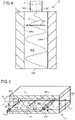
- FIG 4 1 shows a heat exchange device 5 according to an embodiment of the invention.
- the heat exchange device 5 comprises a fluidic component 1, which is preferably the fluidic component from the Figures 1 to 3 is or one of the alternative embodiments in connection with the Figures 1 to 3 have been described.
- the fluidic component 1 generates an oscillating fluid flow 2 which oscillates in its oscillation plane.
- the oscillation level corresponds to the level in figure 4 is spanned by the longitudinal axis A of the fluidic component 1 and the double arrow 202 .
- the heat exchange device 5 comprises a heat exchange body 3.
- the heat exchange body 3 comprises a flow chamber 303 which is delimited by boundary walls. Of the boundary walls are two in figure 4 shown. Their surfaces, which each face the flow chamber 303, are identified by reference numerals 304a, 304b and extend essentially perpendicularly to the plane of oscillation and parallel to the longitudinal axis A of the fluidic component 1.
- the two boundary walls or their surfaces are 304a, 304b arranged parallel to one another on this side and on the other side of the longitudinal axis A of the fluidic component 1 .
- the flow chamber 303 has an inlet opening 301 and an outlet opening 302 which are fluidically opposite to one another and are connected to one another by the flow chamber 303 .
- the fluid flow 2 emerging from the fluid flow source 1 can enter the flow chamber 303 of the heat exchange body 3 through the inlet opening 301 and exit again through the outlet opening 302 from the flow chamber 303 of the heat exchange body 3 .
- the inlet opening 301 of the heat exchange body 3 is arranged immediately downstream of the outlet opening 102 of the fluidic component 1 , so that the fluid stream flows out of the fluidic component 1 directly into the heat exchange body 3 .
- the fluidic component 1 and the boundary walls (or their surfaces 304a, 304b) are positioned relative to one another in such a way that the plane of oscillation is aligned essentially perpendicular to the surfaces 304a, 304b.
- the oscillation angle of the oscillating fluid flow 2 and the distance between the surfaces 304a, 304b and the longitudinal axis A of the fluidic component are selected such that the oscillating fluid jet 2 alternately sweeps the two surfaces 304a, 304b. This means that the surfaces 304a, 304b experience a flow situation that changes over time. In this way, a highly turbulent flow with large-scale coherent (eddy) structures is generated, which would not form without the oscillating fluid flow.
- the fluidic component can be arranged within the flow chamber 303 . More than one fluidic component can also be arranged in the flow chamber 303 .
- the fluidic component(s) then act like turbulators (swirl elements), which additionally swirl the fluid flow.
- the fluidic components can be arranged in series or in parallel, for example.
- FIG 5 a further embodiment of the heat exchange device 5 is shown. This differs from the embodiment figure 4 inter alia in the relative orientation of the fluidic component 1 and the two boundary walls of the flow chamber 303 (or their surfaces facing the flow chamber 303).
- the surfaces are identified by reference numerals 304c and 304d.
- the surfaces 304c, 304d are in figure 5 aligned essentially parallel to the plane of oscillation (not perpendicular as in figure 4 ).
- the oscillation level corresponds to the level in figure 5 is spanned by the longitudinal axis A of the fluidic component 1 and the double arrow 202 .
- an additional turbulator 333 is provided on the surface 304d, which is designed as a web which extends along the surface 304d and essentially perpendicularly to the longitudinal axis A of the fluidic component 1.
- the turbulator 333 is arranged at a distance I 333 from the outlet opening 102 of the fluidic component 1 .
- This distance I 333 is at least twice the width b EX of the outlet opening 102 .
- the installation space (the size of the flow chamber 303 of the heat exchanger body 3) can thus be reduced with the same heat transport capacity if a fluidic component is used as the fluid flow source instead of a perforated nozzle.
- the shape and orientation of the turbulator is in figure 5 only exemplary. Other shapes and/or orientations are also possible. According to an alternative, the heat exchange body 3 has no additional turbulator.
- the outlet opening 102 of the fluidic component 1 can have a depth t EX which corresponds to the distance t 303 between the surfaces 304c, 304d.
- This distance t 303 is the depth of the flow chamber 303 of the heat exchange body 3.
- the outlet opening 102 of the fluidic component 1 borders on the two surfaces 304c, 304d. in the in figure 5
- the depth t EX of the outlet opening 102 of the fluidic component 1 is smaller than the depth t 303 of the flow chamber 303 of the heat exchanger body 3.
- the outlet opening 102 can adjoin one of the two surfaces 304c, 304d and the other of the two surfaces 304c , 304d have a distance t 311 .
- This distance t 311 is preferably smaller than the extension t 333 of the turbulator 333 along the depth t 303 of the flow chamber 303 of the heat exchanger body 3.
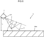
- FIG 6 an embodiment of the heat exchange device 5 is shown, in which heat exchange takes place according to the impingement flow method.
- the fluid flow 2 emerging from the fluidic component 1 flows against the heat exchange body 3 or its surface 304e (for example from the outside) in order to bring about a temperature change in the heat exchange body 3 in this way.
- the fluidic component 1 is arranged at a distance from the surface 304e.
- the longitudinal axis A of the fluidic component 1 encloses an inflow angle ⁇ with the surface 304e which is not equal to zero.
- the angle of attack ⁇ is in figure 6 only exemplary.
- the outlet opening 102 of the fluidic component 1 is arranged at a distance I 14 from the surface 304e.
- the distance I 14 is defined along an axis that extends substantially perpendicularly to the surface 304e.
- the distance I 14 is preferably at least twice as large as the width b EX of the outlet opening 102 of the fluidic component 1. In the case of heat exchange devices with perforated nozzles as the fluid flow source, this distance I 14 must be at least five times the width b EX of the outlet opening 102 in the impingement flow process.
- the installation space (the volume of the heat exchange device 5) can thus be reduced with the same heat transport capacity if a fluidic component is used as the fluid flow source instead of a perforated nozzle.
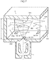
- the heat exchange body 3 comprises a flow chamber 303, which is bounded by a plurality of boundary walls, three of which are in figure 7 are shown. Their surfaces facing the flow chamber 303 bear the reference symbols 304f, 304g, 304h.
- the heat exchange device 5 comprises three fluidic components 1 as fluid flow sources. However, the number of fluid flow sources may vary from three.
- Their outlet openings 102 merge into corresponding inlet openings 301 of the flow chamber 303 of the heat exchange body 3 and are formed in the boundary wall with the surface 304f.
- the longitudinal axes A of the fluidic components 1 extend essentially perpendicularly to the surface 304f and to the surface 304h, which is arranged parallel to the surface 304f.
- the fluid flow 2 exits the outlet openings 102 of the fluidic components 1 through the inlet openings 301 of the heat exchange body 3 into the flow chamber 303 of the heat exchange body 3 and then hits the surface 304h as an impingement flow at the angle of attack ⁇ .
- the distance I 14 from each outlet opening 102 of the fluidic components 1 to the surface 304h along the longitudinal axis A is preferably at least twice the width b EX of the outlet openings 102.
- the flow chamber 303 of the heat exchange body 3 can also have an outlet opening 302 in figure 7 between the boundary walls with the surfaces 304f, 304h is indicated. The fluid flow can then flow out of the flow chamber 303 through the outlet opening 302 .
- the angle of attack ⁇ can also assume other values between 0 and 90°, such as approx. 60°, as in figure 6 is shown as an example.
- the oscillation plane can also be rotated about the longitudinal axis A of the respective fluidic component 1 and have a different orientation than in figure 7 exhibit.
- the flow chamber 303 has an inlet opening instead of the boundary wall with the surface 304g, so that fluid can flow on the one hand through this inlet opening and on the other hand through the inlet openings 301 communicating with the fluidic components 1 into the flow chamber 303.
- the additional inlet openings 301 can create new sources of turbulence.
- the temperature difference of the fluids can be equalized very quickly if the fluid that enters the flow chamber 303 through the inlet opening in the surface 304g and the fluid that enters the flow chamber 303 via the fluidic components 1 have different temperatures .
- the fluidic component 1 can be designed differently in order to generate different jet paths.
- three different beam paths are shown as an example.
- the dashed beam path is essentially sinusoidal
- the dotted beam path is essentially triangular
- the beam path along the dashed line is essentially rectangular.
- the fluidic components 1 can be designed in such a way that they all generate the same jet path, which is also determined by the in figure 7 beam paths shown may deviate.
- the duration of interaction of the oscillating fluid stream with the surfaces will vary.
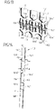
- figure 8 Illustrated schematically is a plan view of a partition 15 intended for placement in a fluid flow source.
- figure 9 shows a perspective view of this partition wall 15, and figure 10 shows a section through this partition wall 15 along the line A'-A".
- figure 10 shows a front wall in addition to the partition wall 15 12 and a rear wall 13 of the fluid flow source 1, between which the partition wall 15 is arranged.
- the fluid flow source 1 with the partition wall 15 can be arranged in relation to a heat exchange body in such a way that the fluid flow emerging from the fluid flow source interacts with the heat exchange body for the purpose of heat exchange.
- the heat exchange body 3 can be formed by the front wall 12 and/or the rear wall 13 so that the fluid flow flowing in the fluid flow source rather than the fluid flow emerging from the fluid flow source interacts with the heat exchange body for the purpose of heat exchange.
- the latter alternative is in figure 10 shown.
- the partition wall 15 extends in a main extension plane and has a first side 151 and a second side 152 opposite the first side 151, wherein in figure 8 the first side 151 faces the viewer and the second side 152 faces away from the viewer.
- the partition wall 15 is not flat, but has a number of protruding from the main plane of deformation, as in particular in the Figures 9 and 10 is recognizable.
- the deformations appearing as concave (convex) on the first side 151 form correspondingly convex (concave) deformations on the second side 152 .
- both the first side 151 and the second side 152 of the partition wall 15 have indentations in sections, the indentations of the first and second side 151, 152 being shaped in a complementary manner and distributed over the partition wall 15.
- the indentations on the first and second side 151, 152 are shaped in such a way that together with the front wall 12 or the rear wall 13 they each form fluidic components 1', 1".
- the indentations on the first side 151 form a plurality of first fluidic components 1'.
- the depressions of the second side 152 form a plurality of second fluidic components 1".
- the partition wall 15 forms three first fluidic components 1' and three second fluidic components 1".
- the first and second fluidic components 1'. , 1" are not fluidically connected to one another, but are always separated from one another by the material of the partition wall 15.
- the first and second fluidic components 1′, 1′′ are arranged next to one another and alternately along a main flow direction (which will be explained later) of the first and second fluidic components 1′, 1′′. This creates a pattern that is repeated across the main flow direction.
- the smallest unit of the pattern is in figure 8 shown bounded by two dashed lines.
- the first and second fluidic components 1', 1" correspond to the basic structure of the fluidic component 1 from the Figures 1 to 3 . Accordingly, in the Figures 8 to 16 , the first and second fluidic components 1 ', 1 "show elements that are also in the fluidic component 1 from the Figures 1 to 3 are embodied, are identified by corresponding reference symbols which carry the suffix ' (for the first fluidic components) or " (for the second fluidic components). In order to avoid repetitions, for the following description of the first and second fluidic components 1', 1" the Figures 8 to 16 also to the description of the fluidic component from the Figures 1 to 3 referred. Only the most relevant features will be described below.
- Each first and second fluidic component 1′, 1′′ of the embodiment from FIGS Figures 8 to 10 comprises a flow chamber 10', 10", through which a fluid stream can flow in each case.
- the flow chambers 10', 10" each comprise an inlet opening 101', 101", via which the fluid stream enters the flow chambers 10', 10", and a Outlet opening 102', 102", via which the fluid flow exits from the flow chambers 10', 10".
- the first and second fluidic components 1', 1" are each mirror-symmetrical with respect to a plane which is essentially perpendicular to the main extension plane of the partition 15 and centrally through the respective inlet opening 101', 101" and through the respective outlet opening 102', 102". However, such symmetry is not mandatory.
- Each flow chamber 10', 10" comprises a main flow channel 103', 103" and, as a means for forming an oscillation of the fluid flow at the outlet opening, two secondary flow channels 104a', 104b', 104a", 104b", which extend in the main plane of extent of the partition 15 , the main flow channel 103', 103" being formed between the two secondary flow channels 104a', 104b', 104a", 104b".
- the number of secondary flow channels can also be different from two.
- the fluid flow moves in the main flow channels 103', 103 "Essentially from the inlet opening 101', 101" to the outlet opening 102', 102" along the so-called main flow direction.
- the first and second fluidic components 1', 1" have the same main flow direction, which in figure 8 marked with arrows. It is a so-called co-current or co-flow situation.
- the inlet opening 101′ and the outlet opening 102′ of the first fluidic components 1′ are offset downstream (viewed in the main flow direction) relative to the inlet opening 101′′ or the outlet opening 102′′ of the second fluidic components 1′′.
- the inlet openings 101′ (101′′) are ) of the first fluidic components 1' (second fluidic components 1") are arranged at the same height as viewed in the main flow direction. The same applies to the outlet openings 102'(102").
- first fluidic component 1′ offset downstream compared to the entire second fluidic component 1′′.
- first fluidic components 1′ can also be offset upstream or downstream from one another.
- the geometry of the flow chambers 10', 10'' would have to be adapted.
- Each main flow passage 103', 103" is fluidly connected to its branch flow passages 104a', 104b', 104a", 104b" immediately downstream of the inlet port 101', 101" and immediately upstream of the outlet port 102', 102".
- the direction of the fluid flow is influenced in such a way that the main flow exiting at the outlet opening 102', 102" oscillates spatially and/or temporally.
- the oscillation takes place in one plane, the so-called oscillation plane. This is parallel to the main plane of extension of the partition wall 15.
- the two secondary flow channels 104a', 104b', 104a", 104b" are here within a fluidic component 1', 1" for example identically shaped and arranged symmetrically with respect to the associated main flow channel 103', 103".
- the bypass channels may not be of identical shape and/or may not be arranged symmetrically.
- the main flow channels 103', 103" are separated from their secondary flow channels 104a', 104b', 104a", 104b" each by an inner block 11a', 11b', 11a", 11b".
- the two blocks 11a', 11b', 11a ", 11b" of a first or second fluidic component 1 ', 1' are in the embodiment of Figures 8 to 10 identical in shape and size and arranged symmetrically with respect to the main flow channel 103', 103". In principle, however, they can also be designed differently and/or not oriented symmetrically.
- the inner blocks 11a', 11b' of the first fluidic components 1' differ in the shape of the inner blocks 11a", 11b" of the second fluidic components 1".
- the shape of the inner blocks 11a', 11b', 11a", 11b" is only exemplary here. However, the inner blocks 11a', 11b', 11a", 11b" should always be shaped and aligned so that the width (Expansion in the skin extension plane of the partition 15 and essentially perpendicular to the main flow direction) of the main flow channels 103', 103" increases downstream.
- the main flow channels 103', 103" have a constant depth (expansion essentially perpendicular to the skin extension plane of the partition 15).
- the depth of both the main flow channel 103' and the main flow channel 103" corresponds to the maximum depth t max , which is caused by the deformation of the Partition 15 is available.
- the width of the main flow channels 103', 103" increases downstream.
- the secondary flow channels 104a', 104b', 104a", 104b" have a non-constant depth.
- the bypass channels 104a′, 104b′, 104a′′, 104b′′ have the maximum depth t max in sections and a reduced depth t red in sections, which is less than the maximum depth t max .
- the reduced depth t red can be half the maximum depth t max , for example. If several sections are formed with a reduced depth t red , they can have the same depth or different depths.
- the maximum depth t max has the bypass channels 104a', 104b'(104a",104b") of the first fluidic components 1' (second fluidic components 1") in the section in which the second fluidic components 1" (first fluidic components 1') have their inner blocks 11a", 11b"(11a',11b'). Furthermore, the secondary flow channels 104a', 104b', 104a", 104b" have the maximum depth t max in the area of the transition to the respective main flow channel 103', 103", which also has the maximum depth t max .
- the sections of maximum depth t max are interrupted by sections of reduced depth t red , the so-called crossing sections.
- the depth of the bypass channels 104a', 104b'(104a",104b") in the direction from their respective inlet to their respective outlet is as follows: Maximum depth t max (like the main flow channel 103'(103")) ⁇ reduced depth t red (intersection with a section of the secondary flow channels 104a", 104b"(104a',104b') of the second fluidic components 1" (first fluidic components 1 ')) ⁇ maximum depth t max (Formation of the inner blocks 11a", 11b"(11a',11b') of the second fluidic components 1" (first fluidic components 1')) ⁇ reduced depth t red (intersection with a section of the bypass channels 104a", 104b" (104a ', 104b') of the second fluidic components 1" (first fluidic components 1')) ⁇ maximum depth t max (like the main flow channel 103'(103")).
- the depth for the two reduced depth sections t red (crossing sections) is equal and equal to half of t max .
- these two crossing sections may have different depths.
- the reduced depth need not be half of t max .
- the distance between adjacent first and second fluidic components 1′, 1′′ can be reduced by the reduced depth of the bypass channels in some sections.
- the outer wall (the wall facing away from the main flow duct 103' (103") and extending essentially perpendicularly to the main extension plane of the partition 15) of the secondary flow ducts 104a', 104b' (104a", 104b") forms in sections the first fluidic components 1' (of the second fluidic components 1") at the same time the inner wall (the wall facing the main fluidic channel 103" (103') and extending essentially perpendicularly to the main extension plane of the partition wall 15) of the inner blocks 11a", 11b" ( 11a', 11b') of the adjacent second fluidic components 1" (first fluidic components 1').
- Said outer wall is shaped in such a way that it gives the main flow channel 103" (103') of the adjacent second fluidic components 1" (first fluidic components 1') a suitable shape for the purpose of forming the oscillation. Furthermore, the inner wall (the wall facing the main flow channel 103' (103'') and extending essentially perpendicularly to the main extension plane of the partition wall 15) of the secondary flow channels 104a', 104b' (104a'', 104b'') of the first fluidic components 1' forms in sections.
- each main flow channel 103', 103" transitions into an outlet channel 107', 107", which, viewed in the plane of oscillation, tapers downstream and ends in the outlet opening 102', 102".
- an outlet extension 108', 108" is provided, which directly adjoins the respective outlet opening 102', 102".
- Upstream of the inlet opening 101', 101" of the flow chambers 10', 10" is a funnel-shaped attachment 106', 106" upstream, which tapers (in the oscillation plane) in the direction of the inlet opening 101', 101" (downstream).
- the first fluidic components 1' differ in shape from the second fluidic components 1": In particular, they differ in terms of the shape of the main flow channel, the side flow channels and the inner blocks.
- the front wall 12 and the rear wall 13 each have a flat surface directed toward the partition wall, with which they rest in sections on the first or second side 151, 152 of the partition wall.
- these surfaces can also be uneven.
- the surfaces should be shaped in such a way that the front wall 12 can rest on the inner blocks 11a′, 11b′ of the first fluidic components 1′ and the rear wall 13 on the inner blocks 11a′′, 11b′′ of the second fluidic components 1′′ to prevent the fluid stream from flowing through in these areas and not to impair the functioning of the bypass channels 104a', 104b', 104a", 104b".
- FIG. 11 In the embodiment off figure 11 are two partitions 15 of the embodiment of FIG Figures 8 to 10 intended for placement in the fluid flow source.
- the partition walls 15 are arranged (stacked) in such a way that their main extension planes run parallel to one another.
- the two partitions 15 are arranged mirror-symmetrically to one another and rest against one another in sections. Areas arise in sections between the two partition walls 15 in which the depth corresponds to twice the depth t max of a partition wall 15 .
- the direction of flow of the main stream is marked with arrows for the first and second fluidic components 1', 1".
- figure 10 for example, be placed between a front wall and a rear wall to form a fluid flow source/heat exchange device. It is also possible to have more than two partitions 15 in analogy to the embodiment figure 11 to be stacked so that immediately adjacent partitions are always mirror-symmetrical to one another.
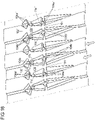
- FIGs 12 to 14 a further embodiment for a partition wall 15 is shown. while showing figure 12 a plan view of the main extension plane of the partition wall 15, figure 13 a perspective view and figure 14 a sectional view transverse to the main plane of the partition wall 15.
- figure 14 is the partition 15 again shown together with a front wall 12 and a rear wall 13, which abut the partition wall 15 in sections. Together they form a heat exchange device 5.
- This embodiment of the partition 15 differs from that of Figures 8 to 10 in particular that the shapes of the main flow channels 103', 103", the side flow channels 104a', 104b', 104a", 104b" and the inner blocks 11a', 11b' are more angular (less rounded).
- first and the second fluidic components 1', 1" are identically shaped and aligned with one another in such a way that their main flow directions are opposite to one another.
- the main flow directions are indicated by arrows.
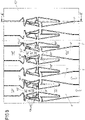
- FIG 15 are three partitions 15 of the embodiment of FIG Figures 12 to 14 shown in a stacked arrangement intended for placement in a fluid flow source.
- two directly adjacent partitions 15 are aligned in a mirror-symmetrical manner with respect to one another and rest against one another in sections. This means that the two outer partitions have the same orientation.
- first and second fluidic components 1', 1" are formed with (compared to a single partition, which as in figure 14 is arranged between a flat front wall 12 and a flat rear wall 13) twice the depth of the arrows in figure 15 show the main flow direction for the first and second fluidic components 1 ', 1 ".
- the three partitions 15 can in the arrangement shown in analogy to figure 14 for example, be placed between a front wall and a rear wall to form a fluid flow source/heat exchange device.
- the number of partitions is 15 in figure 15 only as an example and can deviate from three. In this case, immediately adjacent partition walls should be arranged mirror-symmetrically to one another.
- FIG 16 a further embodiment for a partition wall 15 is shown.
- the first and second fluidic components 1', 1" also have the same main flow direction here.
- the main flow channels 103', 103", secondary flow channels 104a', 104b', 104a", 104b" and inner blocks 11a', 11b', 11a” , 11b" have as in the embodiment of FIG Figures 8 to 10 more rounded shapes.
- the first and the second fluidic components 1', 1" (main flow channel 103', 103", bypass channels 104a', 104b', 104a", 104b" and inner blocks 11a', 11b', 11a", 11b") are almost identically shaped.
- the inlet opening 101' and the outlet opening 102' of the first fluidic components 1' are arranged at the same height (viewed in the fluid flow direction) as the inlet opening 101" or the outlet opening 102" of the second fluidic components 1".
- All in the Figures 8 to 16 illustrated embodiments of the partition are space-optimized and suitable for compact heat exchange devices / fluid flow sources.
- the individual elements (partition walls, front wall, rear wall) of the heat exchange device/fluid flow source can be produced inexpensively, for example by means of forming processes.
- these individual elements can be releasably connected to one another after they have been arranged relative to one another as intended.
- the individual elements can be clamped together in such a way that they rest flat against one another in sections. A seal can also be achieved by the bracing. Due to this modular design of the heat exchange device, partitions can be easily replaced and cleaning of the individual elements can be made possible in the event of maintenance.
- first fluidic components 1' and the second fluidic components 1" are arranged one behind the other in the direction of fluid flow and to connect them fluidly.
- the fluid flow that emerges from the outlet opening 102', 102" of a fluidic component arranged upstream 1′, 1′′ exit into the inlet opening 101′, 101′′ of the fluidic component 1′, 1′′, which is fluidically connected downstream.
- First and second fluidic components 1′, 1′′ can be provided (for example, alternating) viewed in the direction of fluid flow. .
- only first fluidic components 1' or only second fluidic components 1" can be arranged one behind the other and fluidly connected to one another. Even in a series connection, the fluidic connection is not created by the crossing of first and second fluidic components.
- the series connection can be advantageous to increase heat exchange.
Landscapes
- Engineering & Computer Science (AREA)
- Mechanical Engineering (AREA)
- General Engineering & Computer Science (AREA)
- Physics & Mathematics (AREA)
- Thermal Sciences (AREA)
- Cooling Or The Like Of Electrical Apparatus (AREA)
- Physical Or Chemical Processes And Apparatus (AREA)
- Details Of Heat-Exchange And Heat-Transfer (AREA)
- Heat-Exchange Devices With Radiators And Conduit Assemblies (AREA)
Applications Claiming Priority (2)
| Application Number | Priority Date | Filing Date | Title |
|---|---|---|---|
| DE102017212961.1A DE102017212961A1 (de) | 2017-07-27 | 2017-07-27 | Fluidisches Bauteil |
| PCT/EP2018/069816 WO2019020530A1 (de) | 2017-07-27 | 2018-07-20 | Wärmetauschvorrichtung |
Publications (2)
| Publication Number | Publication Date |
|---|---|
| EP3658837A1 EP3658837A1 (de) | 2020-06-03 |
| EP3658837B1 true EP3658837B1 (de) | 2022-04-20 |
Family
ID=63108520
Family Applications (1)
| Application Number | Title | Priority Date | Filing Date |
|---|---|---|---|
| EP18750114.3A Not-in-force EP3658837B1 (de) | 2017-07-27 | 2018-07-20 | Verwendung eines wärmetauschkörpers und einer fluidstromquelle als wärmetauschvorrichtung |
Country Status (6)
| Country | Link |
|---|---|
| US (1) | US20200240724A1 (da) |
| EP (1) | EP3658837B1 (da) |
| CN (1) | CN110998213B (da) |
| DE (1) | DE102017212961A1 (da) |
| DK (1) | DK3658837T3 (da) |
| WO (1) | WO2019020530A1 (da) |
Families Citing this family (4)
| Publication number | Priority date | Publication date | Assignee | Title |
|---|---|---|---|---|
| WO2023107618A1 (en) * | 2021-12-08 | 2023-06-15 | Worcester Polytechnic Institute | Passive flow control for captive vortex |
| CN114473304B (zh) * | 2022-02-28 | 2024-08-02 | 台州竞添机电有限公司 | 一种电焊机电子元件降温装置 |
| CN117365752A (zh) * | 2023-09-04 | 2024-01-09 | 南京航空航天大学 | 基于周期性振荡射流的双出口预旋冷却系统及方法 |
| DE202024103798U1 (de) * | 2024-07-09 | 2024-07-18 | Polytec Plastics Germany Gmbh & Co. Kg | Ölbenetzungsvorrichtung zur Schmierung von Kraftfahrzeugkomponenten, Schmierungsvorrichtung für Getriebekomponenten und Getriebekomponente eines Fahrzeugs |
Family Cites Families (19)
| Publication number | Priority date | Publication date | Assignee | Title |
|---|---|---|---|---|
| US4645126A (en) * | 1978-11-08 | 1987-02-24 | Bowles Fluidics Corporation | Cold weather fluidic windshield washer method |
| DE3070916D1 (en) * | 1979-04-17 | 1985-09-05 | Bowles Fluidics Corp | Air flow system |
| DE3400934A1 (de) * | 1983-03-31 | 1984-12-06 | Knorr-Bremse Fluidics GmbH, 8000 München | Koerperpflege- und koerperreinigungsgeraet, insbesondere zahn- und gesichtsreinigungsbuerste oder munddusche und fluidischer oszillator, insbesondere zur verwendung in solchen geraeten |
| US5238056A (en) * | 1990-03-30 | 1993-08-24 | The United States Of America As Represented By The Administrator Of The National Aeronautics And Space Administration | Heat exchanger with oscillating flow |
| US5749525A (en) * | 1996-04-19 | 1998-05-12 | Bowles Fluidics Corporation | Fluidic washer systems for vehicles |
| DE20105068U1 (de) * | 2001-03-23 | 2001-06-07 | Supellex Ag, Frauenfeld | Aufbau für einen Wärmetauscher |
| US6607356B2 (en) | 2002-01-11 | 2003-08-19 | General Electric Company | Crossover cooled airfoil trailing edge |
| KR100569175B1 (ko) * | 2002-08-07 | 2006-04-07 | 가부시키가이샤 덴소 | 카운터 스트림 모드 진동유동 열전달 장치 |
| CN1254314C (zh) * | 2002-08-22 | 2006-05-03 | 阿斯莫株式会社 | 清洗喷嘴和清洗装置 |
| EP1472966A2 (en) * | 2003-05-01 | 2004-11-03 | Epenhuysen Chemie N.V. | Machine dish-washing process |
| US20070295840A1 (en) * | 2003-09-29 | 2007-12-27 | Bowles Fluidics Corporation | Fluidic oscillators and enclosures with split throats |
| WO2005111386A1 (de) * | 2004-05-07 | 2005-11-24 | Behr Gmbh & Co. Kg | Wärmetauscher, insbesondere für abgaskühler von brennkraftmaschinen |
| JP4303263B2 (ja) | 2006-01-02 | 2009-07-29 | 株式会社ノビタ | 洗浄機用瞬間式温水装置 |
| GB0715979D0 (en) | 2007-08-15 | 2007-09-26 | Rolls Royce Plc | Heat exchanger |
| KR101247648B1 (ko) * | 2010-10-01 | 2013-03-29 | 한국그린에너지 주식회사 | 어류저장조의 수온조절장치 |
| SE536618C2 (sv) * | 2010-10-22 | 2014-04-01 | Alfa Laval Corp Ab | Värmeväxlarplatta och plattvärmeväxlare |
| CN102059178B (zh) * | 2010-12-02 | 2012-07-04 | 厦门松霖科技有限公司 | 一种出脉动喷溅水的机构 |
| DE102014116182A1 (de) * | 2014-11-06 | 2016-05-12 | Boots Innovations Gmbh | Verfahren und Vorrichtung zur Erzeugung einer gepulsten Fluidströmung |
| DE102015222771B3 (de) * | 2015-11-18 | 2017-05-18 | Technische Universität Berlin | Fluidisches Bauteil |
-
2017
- 2017-07-27 DE DE102017212961.1A patent/DE102017212961A1/de not_active Withdrawn
-
2018
- 2018-07-20 US US16/634,556 patent/US20200240724A1/en not_active Abandoned
- 2018-07-20 DK DK18750114.3T patent/DK3658837T3/da active
- 2018-07-20 EP EP18750114.3A patent/EP3658837B1/de not_active Not-in-force
- 2018-07-20 CN CN201880050421.1A patent/CN110998213B/zh active Active
- 2018-07-20 WO PCT/EP2018/069816 patent/WO2019020530A1/de not_active Ceased
Also Published As
| Publication number | Publication date |
|---|---|
| DK3658837T3 (da) | 2022-07-11 |
| WO2019020530A1 (de) | 2019-01-31 |
| CN110998213A (zh) | 2020-04-10 |
| EP3658837A1 (de) | 2020-06-03 |
| DE102017212961A1 (de) | 2019-01-31 |
| CN110998213B (zh) | 2024-10-29 |
| US20200240724A1 (en) | 2020-07-30 |
Similar Documents
| Publication | Publication Date | Title |
|---|---|---|
| EP3658837B1 (de) | Verwendung eines wärmetauschkörpers und einer fluidstromquelle als wärmetauschvorrichtung | |
| EP1654508B2 (de) | Wärmeübertrager sowie verfahren zu dessen herstellung | |
| DE10001109B4 (de) | Gekühlte Schaufel für eine Gasturbine | |
| EP2491327B1 (de) | Wärmeübertragerplatte und verdampfer mit einer solchen | |
| DE102004045923A1 (de) | Strömungskanal für einen Wärmeübertrager und Wärmeübertrager mit derartigen Strömungskanälen | |
| EP1091185A2 (de) | Plattenwärmetauscher | |
| DE102015015598A1 (de) | Kühlung von Triebwerkskomponenten | |
| DE102006048305A1 (de) | Plattenwärmetauscher | |
| WO2017194525A1 (de) | Fluidisches bauteil | |
| WO2010015433A1 (de) | Wärmeübertragungseinheit für eine verbrennungskraftmaschine | |
| DE102009050500B4 (de) | Wärmeübertragerplatte und Verdampfer mit einer solchen | |
| DE102008029096B4 (de) | Verdampfer für ein Abwärmenutzungssystem | |
| EP1668236A1 (de) | Brennkammer mit kühleinrichtung und verfahren zur herstellung der brennkammer | |
| DE3134465T1 (de) | Tubular-lamellar heat exchanger | |
| EP1792135B1 (de) | Wärmetauscher für kraftfahrzeuge | |
| DE112018001282B4 (de) | Kühlstruktur für eine Turbinenschaufel | |
| DE2127454A1 (de) | Gasturbine | |
| DE102015226471B4 (de) | Fluidische Oszillatorvorrichtung | |
| DE102017210276A1 (de) | Wärmetauscher, insbesondere Abgaswärmetauscher, für ein Kraftfahrzeug | |
| DE102011113045A1 (de) | Kreuzstrom-Wärmeübertrager | |
| EP2678629B1 (de) | Wärmetauscher | |
| EP3625511A1 (de) | Vorrichtung zum kühlen, wärmen oder wärmeübertragen | |
| EP2711658A2 (de) | Wärmeübertrager | |
| EP4089357B1 (de) | Wärmetauscher | |
| DE202011110052U1 (de) | Plattenwärmetauscher |
Legal Events
| Date | Code | Title | Description |
|---|---|---|---|
| STAA | Information on the status of an ep patent application or granted ep patent |
Free format text: STATUS: UNKNOWN |
|
| STAA | Information on the status of an ep patent application or granted ep patent |
Free format text: STATUS: THE INTERNATIONAL PUBLICATION HAS BEEN MADE |
|
| PUAI | Public reference made under article 153(3) epc to a published international application that has entered the european phase |
Free format text: ORIGINAL CODE: 0009012 |
|
| STAA | Information on the status of an ep patent application or granted ep patent |
Free format text: STATUS: REQUEST FOR EXAMINATION WAS MADE |
|
| 17P | Request for examination filed |
Effective date: 20200211 |
|
| AK | Designated contracting states |
Kind code of ref document: A1 Designated state(s): AL AT BE BG CH CY CZ DE DK EE ES FI FR GB GR HR HU IE IS IT LI LT LU LV MC MK MT NL NO PL PT RO RS SE SI SK SM TR |
|
| AX | Request for extension of the european patent |
Extension state: BA ME |
|
| DAV | Request for validation of the european patent (deleted) | ||
| DAX | Request for extension of the european patent (deleted) | ||
| STAA | Information on the status of an ep patent application or granted ep patent |
Free format text: STATUS: EXAMINATION IS IN PROGRESS |
|
| 17Q | First examination report despatched |
Effective date: 20201223 |
|
| GRAP | Despatch of communication of intention to grant a patent |
Free format text: ORIGINAL CODE: EPIDOSNIGR1 |
|
| STAA | Information on the status of an ep patent application or granted ep patent |
Free format text: STATUS: GRANT OF PATENT IS INTENDED |
|
| INTG | Intention to grant announced |
Effective date: 20211115 |
|
| GRAS | Grant fee paid |
Free format text: ORIGINAL CODE: EPIDOSNIGR3 |
|
| GRAA | (expected) grant |
Free format text: ORIGINAL CODE: 0009210 |
|
| STAA | Information on the status of an ep patent application or granted ep patent |
Free format text: STATUS: THE PATENT HAS BEEN GRANTED |
|
| AK | Designated contracting states |
Kind code of ref document: B1 Designated state(s): AL AT BE BG CH CY CZ DE DK EE ES FI FR GB GR HR HU IE IS IT LI LT LU LV MC MK MT NL NO PL PT RO RS SE SI SK SM TR |
|
| REG | Reference to a national code |
Ref country code: GB Ref legal event code: FG4D Free format text: NOT ENGLISH |
|
| REG | Reference to a national code |
Ref country code: CH Ref legal event code: EP |
|
| REG | Reference to a national code |
Ref country code: IE Ref legal event code: FG4D Free format text: LANGUAGE OF EP DOCUMENT: GERMAN |
|
| REG | Reference to a national code |
Ref country code: DE Ref legal event code: R096 Ref document number: 502018009450 Country of ref document: DE |
|
| REG | Reference to a national code |
Ref country code: AT Ref legal event code: REF Ref document number: 1485446 Country of ref document: AT Kind code of ref document: T Effective date: 20220515 |
|
| REG | Reference to a national code |
Ref country code: NL Ref legal event code: FP |
|
| REG | Reference to a national code |
Ref country code: DK Ref legal event code: T3 Effective date: 20220704 |
|
| REG | Reference to a national code |
Ref country code: LT Ref legal event code: MG9D |
|
| PG25 | Lapsed in a contracting state [announced via postgrant information from national office to epo] |
Ref country code: SE Free format text: LAPSE BECAUSE OF FAILURE TO SUBMIT A TRANSLATION OF THE DESCRIPTION OR TO PAY THE FEE WITHIN THE PRESCRIBED TIME-LIMIT Effective date: 20220420 Ref country code: PT Free format text: LAPSE BECAUSE OF FAILURE TO SUBMIT A TRANSLATION OF THE DESCRIPTION OR TO PAY THE FEE WITHIN THE PRESCRIBED TIME-LIMIT Effective date: 20220822 Ref country code: NO Free format text: LAPSE BECAUSE OF FAILURE TO SUBMIT A TRANSLATION OF THE DESCRIPTION OR TO PAY THE FEE WITHIN THE PRESCRIBED TIME-LIMIT Effective date: 20220720 Ref country code: LT Free format text: LAPSE BECAUSE OF FAILURE TO SUBMIT A TRANSLATION OF THE DESCRIPTION OR TO PAY THE FEE WITHIN THE PRESCRIBED TIME-LIMIT Effective date: 20220420 Ref country code: HR Free format text: LAPSE BECAUSE OF FAILURE TO SUBMIT A TRANSLATION OF THE DESCRIPTION OR TO PAY THE FEE WITHIN THE PRESCRIBED TIME-LIMIT Effective date: 20220420 Ref country code: GR Free format text: LAPSE BECAUSE OF FAILURE TO SUBMIT A TRANSLATION OF THE DESCRIPTION OR TO PAY THE FEE WITHIN THE PRESCRIBED TIME-LIMIT Effective date: 20220721 Ref country code: FI Free format text: LAPSE BECAUSE OF FAILURE TO SUBMIT A TRANSLATION OF THE DESCRIPTION OR TO PAY THE FEE WITHIN THE PRESCRIBED TIME-LIMIT Effective date: 20220420 Ref country code: ES Free format text: LAPSE BECAUSE OF FAILURE TO SUBMIT A TRANSLATION OF THE DESCRIPTION OR TO PAY THE FEE WITHIN THE PRESCRIBED TIME-LIMIT Effective date: 20220420 Ref country code: BG Free format text: LAPSE BECAUSE OF FAILURE TO SUBMIT A TRANSLATION OF THE DESCRIPTION OR TO PAY THE FEE WITHIN THE PRESCRIBED TIME-LIMIT Effective date: 20220720 |
|
| PG25 | Lapsed in a contracting state [announced via postgrant information from national office to epo] |
Ref country code: RS Free format text: LAPSE BECAUSE OF FAILURE TO SUBMIT A TRANSLATION OF THE DESCRIPTION OR TO PAY THE FEE WITHIN THE PRESCRIBED TIME-LIMIT Effective date: 20220420 Ref country code: PL Free format text: LAPSE BECAUSE OF FAILURE TO SUBMIT A TRANSLATION OF THE DESCRIPTION OR TO PAY THE FEE WITHIN THE PRESCRIBED TIME-LIMIT Effective date: 20220420 Ref country code: LV Free format text: LAPSE BECAUSE OF FAILURE TO SUBMIT A TRANSLATION OF THE DESCRIPTION OR TO PAY THE FEE WITHIN THE PRESCRIBED TIME-LIMIT Effective date: 20220420 Ref country code: IS Free format text: LAPSE BECAUSE OF FAILURE TO SUBMIT A TRANSLATION OF THE DESCRIPTION OR TO PAY THE FEE WITHIN THE PRESCRIBED TIME-LIMIT Effective date: 20220820 |
|
| REG | Reference to a national code |
Ref country code: DE Ref legal event code: R097 Ref document number: 502018009450 Country of ref document: DE |
|
| PG25 | Lapsed in a contracting state [announced via postgrant information from national office to epo] |
Ref country code: SM Free format text: LAPSE BECAUSE OF FAILURE TO SUBMIT A TRANSLATION OF THE DESCRIPTION OR TO PAY THE FEE WITHIN THE PRESCRIBED TIME-LIMIT Effective date: 20220420 Ref country code: SK Free format text: LAPSE BECAUSE OF FAILURE TO SUBMIT A TRANSLATION OF THE DESCRIPTION OR TO PAY THE FEE WITHIN THE PRESCRIBED TIME-LIMIT Effective date: 20220420 Ref country code: RO Free format text: LAPSE BECAUSE OF FAILURE TO SUBMIT A TRANSLATION OF THE DESCRIPTION OR TO PAY THE FEE WITHIN THE PRESCRIBED TIME-LIMIT Effective date: 20220420 Ref country code: EE Free format text: LAPSE BECAUSE OF FAILURE TO SUBMIT A TRANSLATION OF THE DESCRIPTION OR TO PAY THE FEE WITHIN THE PRESCRIBED TIME-LIMIT Effective date: 20220420 Ref country code: CZ Free format text: LAPSE BECAUSE OF FAILURE TO SUBMIT A TRANSLATION OF THE DESCRIPTION OR TO PAY THE FEE WITHIN THE PRESCRIBED TIME-LIMIT Effective date: 20220420 |
|
| PLBE | No opposition filed within time limit |
Free format text: ORIGINAL CODE: 0009261 |
|
| STAA | Information on the status of an ep patent application or granted ep patent |
Free format text: STATUS: NO OPPOSITION FILED WITHIN TIME LIMIT |
|
| PG25 | Lapsed in a contracting state [announced via postgrant information from national office to epo] |
Ref country code: MC Free format text: LAPSE BECAUSE OF FAILURE TO SUBMIT A TRANSLATION OF THE DESCRIPTION OR TO PAY THE FEE WITHIN THE PRESCRIBED TIME-LIMIT Effective date: 20220420 |
|
| REG | Reference to a national code |
Ref country code: CH Ref legal event code: PL |
|
| 26N | No opposition filed |
Effective date: 20230123 |
|
| REG | Reference to a national code |
Ref country code: BE Ref legal event code: MM Effective date: 20220731 |
|
| PG25 | Lapsed in a contracting state [announced via postgrant information from national office to epo] |
Ref country code: AL Free format text: LAPSE BECAUSE OF FAILURE TO SUBMIT A TRANSLATION OF THE DESCRIPTION OR TO PAY THE FEE WITHIN THE PRESCRIBED TIME-LIMIT Effective date: 20220420 |
|
| PG25 | Lapsed in a contracting state [announced via postgrant information from national office to epo] |
Ref country code: LU Free format text: LAPSE BECAUSE OF NON-PAYMENT OF DUE FEES Effective date: 20220720 Ref country code: LI Free format text: LAPSE BECAUSE OF NON-PAYMENT OF DUE FEES Effective date: 20220731 Ref country code: CH Free format text: LAPSE BECAUSE OF NON-PAYMENT OF DUE FEES Effective date: 20220731 |
|
| PG25 | Lapsed in a contracting state [announced via postgrant information from national office to epo] |
Ref country code: SI Free format text: LAPSE BECAUSE OF FAILURE TO SUBMIT A TRANSLATION OF THE DESCRIPTION OR TO PAY THE FEE WITHIN THE PRESCRIBED TIME-LIMIT Effective date: 20220420 Ref country code: BE Free format text: LAPSE BECAUSE OF NON-PAYMENT OF DUE FEES Effective date: 20220731 |
|
| PG25 | Lapsed in a contracting state [announced via postgrant information from national office to epo] |
Ref country code: IE Free format text: LAPSE BECAUSE OF NON-PAYMENT OF DUE FEES Effective date: 20220720 |
|
| PG25 | Lapsed in a contracting state [announced via postgrant information from national office to epo] |
Ref country code: IT Free format text: LAPSE BECAUSE OF FAILURE TO SUBMIT A TRANSLATION OF THE DESCRIPTION OR TO PAY THE FEE WITHIN THE PRESCRIBED TIME-LIMIT Effective date: 20220420 |
|
| PG25 | Lapsed in a contracting state [announced via postgrant information from national office to epo] |
Ref country code: MK Free format text: LAPSE BECAUSE OF FAILURE TO SUBMIT A TRANSLATION OF THE DESCRIPTION OR TO PAY THE FEE WITHIN THE PRESCRIBED TIME-LIMIT Effective date: 20220420 Ref country code: CY Free format text: LAPSE BECAUSE OF FAILURE TO SUBMIT A TRANSLATION OF THE DESCRIPTION OR TO PAY THE FEE WITHIN THE PRESCRIBED TIME-LIMIT Effective date: 20220420 |
|
| PG25 | Lapsed in a contracting state [announced via postgrant information from national office to epo] |
Ref country code: HU Free format text: LAPSE BECAUSE OF FAILURE TO SUBMIT A TRANSLATION OF THE DESCRIPTION OR TO PAY THE FEE WITHIN THE PRESCRIBED TIME-LIMIT; INVALID AB INITIO Effective date: 20180720 |
|
| PGFP | Annual fee paid to national office [announced via postgrant information from national office to epo] |
Ref country code: NL Payment date: 20240722 Year of fee payment: 7 |
|
| REG | Reference to a national code |
Ref country code: AT Ref legal event code: MM01 Ref document number: 1485446 Country of ref document: AT Kind code of ref document: T Effective date: 20230720 |
|
| PG25 | Lapsed in a contracting state [announced via postgrant information from national office to epo] |
Ref country code: MT Free format text: LAPSE BECAUSE OF FAILURE TO SUBMIT A TRANSLATION OF THE DESCRIPTION OR TO PAY THE FEE WITHIN THE PRESCRIBED TIME-LIMIT Effective date: 20220420 |
|
| PGFP | Annual fee paid to national office [announced via postgrant information from national office to epo] |
Ref country code: DE Payment date: 20240718 Year of fee payment: 7 |
|
| PGFP | Annual fee paid to national office [announced via postgrant information from national office to epo] |
Ref country code: DK Payment date: 20240722 Year of fee payment: 7 |
|
| PGFP | Annual fee paid to national office [announced via postgrant information from national office to epo] |
Ref country code: GB Payment date: 20240723 Year of fee payment: 7 |
|
| PGFP | Annual fee paid to national office [announced via postgrant information from national office to epo] |
Ref country code: FR Payment date: 20240724 Year of fee payment: 7 |
|
| PG25 | Lapsed in a contracting state [announced via postgrant information from national office to epo] |
Ref country code: AT Free format text: LAPSE BECAUSE OF NON-PAYMENT OF DUE FEES Effective date: 20230720 |
|
| PG25 | Lapsed in a contracting state [announced via postgrant information from national office to epo] |
Ref country code: AT Free format text: LAPSE BECAUSE OF NON-PAYMENT OF DUE FEES Effective date: 20230720 |
|
| PG25 | Lapsed in a contracting state [announced via postgrant information from national office to epo] |
Ref country code: BG Free format text: LAPSE BECAUSE OF FAILURE TO SUBMIT A TRANSLATION OF THE DESCRIPTION OR TO PAY THE FEE WITHIN THE PRESCRIBED TIME-LIMIT Effective date: 20220420 |
|
| PG25 | Lapsed in a contracting state [announced via postgrant information from national office to epo] |
Ref country code: BG Free format text: LAPSE BECAUSE OF FAILURE TO SUBMIT A TRANSLATION OF THE DESCRIPTION OR TO PAY THE FEE WITHIN THE PRESCRIBED TIME-LIMIT Effective date: 20220420 |
|
| PG25 | Lapsed in a contracting state [announced via postgrant information from national office to epo] |
Ref country code: TR Free format text: LAPSE BECAUSE OF FAILURE TO SUBMIT A TRANSLATION OF THE DESCRIPTION OR TO PAY THE FEE WITHIN THE PRESCRIBED TIME-LIMIT Effective date: 20220420 |
|
| REG | Reference to a national code |
Ref country code: DE Ref legal event code: R119 Ref document number: 502018009450 Country of ref document: DE |
|
| REG | Reference to a national code |
Ref country code: DK Ref legal event code: EBP Effective date: 20250731 |
|
| REG | Reference to a national code |
Ref country code: NL Ref legal event code: MM Effective date: 20250801 |
|
| GBPC | Gb: european patent ceased through non-payment of renewal fee |
Effective date: 20250720 |
|
| PG25 | Lapsed in a contracting state [announced via postgrant information from national office to epo] |
Ref country code: GB Free format text: LAPSE BECAUSE OF NON-PAYMENT OF DUE FEES Effective date: 20250720 |
|
| PG25 | Lapsed in a contracting state [announced via postgrant information from national office to epo] |
Ref country code: DE Free format text: LAPSE BECAUSE OF NON-PAYMENT OF DUE FEES Effective date: 20260203 |
|
| PGFP | Annual fee paid to national office [announced via postgrant information from national office to epo] |
Ref country code: AT Payment date: 20260410 Year of fee payment: 5 |
|
| PG25 | Lapsed in a contracting state [announced via postgrant information from national office to epo] |
Ref country code: NL Free format text: LAPSE BECAUSE OF NON-PAYMENT OF DUE FEES Effective date: 20250801 |
|
| PG25 | Lapsed in a contracting state [announced via postgrant information from national office to epo] |
Ref country code: FR Free format text: LAPSE BECAUSE OF NON-PAYMENT OF DUE FEES Effective date: 20250731 |