EP3658764B1 - Dosierventil für einen gasförmigen brennstoff - Google Patents
Dosierventil für einen gasförmigen brennstoff Download PDFInfo
- Publication number
- EP3658764B1 EP3658764B1 EP18742790.1A EP18742790A EP3658764B1 EP 3658764 B1 EP3658764 B1 EP 3658764B1 EP 18742790 A EP18742790 A EP 18742790A EP 3658764 B1 EP3658764 B1 EP 3658764B1
- Authority
- EP
- European Patent Office
- Prior art keywords
- closure element
- pressure
- valve
- dosing valve
- valve seat
- Prior art date
- Legal status (The legal status is an assumption and is not a legal conclusion. Google has not performed a legal analysis and makes no representation as to the accuracy of the status listed.)
- Active
Links
Images


Classifications
-
- F—MECHANICAL ENGINEERING; LIGHTING; HEATING; WEAPONS; BLASTING
- F02—COMBUSTION ENGINES; HOT-GAS OR COMBUSTION-PRODUCT ENGINE PLANTS
- F02M—SUPPLYING COMBUSTION ENGINES IN GENERAL WITH COMBUSTIBLE MIXTURES OR CONSTITUENTS THEREOF
- F02M21/00—Apparatus for supplying engines with non-liquid fuels, e.g. gaseous fuels stored in liquid form
- F02M21/02—Apparatus for supplying engines with non-liquid fuels, e.g. gaseous fuels stored in liquid form for gaseous fuels
- F02M21/0218—Details on the gaseous fuel supply system, e.g. tanks, valves, pipes, pumps, rails, injectors or mixers
- F02M21/0248—Injectors
- F02M21/0251—Details of actuators therefor
- F02M21/0254—Electric actuators, e.g. solenoid or piezoelectric
-
- F—MECHANICAL ENGINEERING; LIGHTING; HEATING; WEAPONS; BLASTING
- F02—COMBUSTION ENGINES; HOT-GAS OR COMBUSTION-PRODUCT ENGINE PLANTS
- F02M—SUPPLYING COMBUSTION ENGINES IN GENERAL WITH COMBUSTIBLE MIXTURES OR CONSTITUENTS THEREOF
- F02M21/00—Apparatus for supplying engines with non-liquid fuels, e.g. gaseous fuels stored in liquid form
- F02M21/02—Apparatus for supplying engines with non-liquid fuels, e.g. gaseous fuels stored in liquid form for gaseous fuels
- F02M21/0218—Details on the gaseous fuel supply system, e.g. tanks, valves, pipes, pumps, rails, injectors or mixers
- F02M21/023—Valves; Pressure or flow regulators in the fuel supply or return system
-
- F—MECHANICAL ENGINEERING; LIGHTING; HEATING; WEAPONS; BLASTING
- F02—COMBUSTION ENGINES; HOT-GAS OR COMBUSTION-PRODUCT ENGINE PLANTS
- F02M—SUPPLYING COMBUSTION ENGINES IN GENERAL WITH COMBUSTIBLE MIXTURES OR CONSTITUENTS THEREOF
- F02M21/00—Apparatus for supplying engines with non-liquid fuels, e.g. gaseous fuels stored in liquid form
- F02M21/02—Apparatus for supplying engines with non-liquid fuels, e.g. gaseous fuels stored in liquid form for gaseous fuels
- F02M21/0218—Details on the gaseous fuel supply system, e.g. tanks, valves, pipes, pumps, rails, injectors or mixers
- F02M21/023—Valves; Pressure or flow regulators in the fuel supply or return system
- F02M21/0239—Pressure or flow regulators therefor
-
- F—MECHANICAL ENGINEERING; LIGHTING; HEATING; WEAPONS; BLASTING
- F02—COMBUSTION ENGINES; HOT-GAS OR COMBUSTION-PRODUCT ENGINE PLANTS
- F02M—SUPPLYING COMBUSTION ENGINES IN GENERAL WITH COMBUSTIBLE MIXTURES OR CONSTITUENTS THEREOF
- F02M21/00—Apparatus for supplying engines with non-liquid fuels, e.g. gaseous fuels stored in liquid form
- F02M21/02—Apparatus for supplying engines with non-liquid fuels, e.g. gaseous fuels stored in liquid form for gaseous fuels
- F02M21/0218—Details on the gaseous fuel supply system, e.g. tanks, valves, pipes, pumps, rails, injectors or mixers
- F02M21/0245—High pressure fuel supply systems; Rails; Pumps; Arrangement of valves
-
- F—MECHANICAL ENGINEERING; LIGHTING; HEATING; WEAPONS; BLASTING
- F02—COMBUSTION ENGINES; HOT-GAS OR COMBUSTION-PRODUCT ENGINE PLANTS
- F02M—SUPPLYING COMBUSTION ENGINES IN GENERAL WITH COMBUSTIBLE MIXTURES OR CONSTITUENTS THEREOF
- F02M21/00—Apparatus for supplying engines with non-liquid fuels, e.g. gaseous fuels stored in liquid form
- F02M21/02—Apparatus for supplying engines with non-liquid fuels, e.g. gaseous fuels stored in liquid form for gaseous fuels
- F02M21/0218—Details on the gaseous fuel supply system, e.g. tanks, valves, pipes, pumps, rails, injectors or mixers
- F02M21/0248—Injectors
- F02M21/0257—Details of the valve closing elements, e.g. valve seats, stems or arrangement of flow passages
-
- F—MECHANICAL ENGINEERING; LIGHTING; HEATING; WEAPONS; BLASTING
- F16—ENGINEERING ELEMENTS AND UNITS; GENERAL MEASURES FOR PRODUCING AND MAINTAINING EFFECTIVE FUNCTIONING OF MACHINES OR INSTALLATIONS; THERMAL INSULATION IN GENERAL
- F16K—VALVES; TAPS; COCKS; ACTUATING-FLOATS; DEVICES FOR VENTING OR AERATING
- F16K31/00—Actuating devices; Operating means; Releasing devices
- F16K31/02—Actuating devices; Operating means; Releasing devices electric; magnetic
- F16K31/06—Actuating devices; Operating means; Releasing devices electric; magnetic using a magnet, e.g. diaphragm valves, cutting off by means of a liquid
- F16K31/0644—One-way valve
- F16K31/0655—Lift valves
-
- F—MECHANICAL ENGINEERING; LIGHTING; HEATING; WEAPONS; BLASTING
- F16—ENGINEERING ELEMENTS AND UNITS; GENERAL MEASURES FOR PRODUCING AND MAINTAINING EFFECTIVE FUNCTIONING OF MACHINES OR INSTALLATIONS; THERMAL INSULATION IN GENERAL
- F16K—VALVES; TAPS; COCKS; ACTUATING-FLOATS; DEVICES FOR VENTING OR AERATING
- F16K31/00—Actuating devices; Operating means; Releasing devices
- F16K31/02—Actuating devices; Operating means; Releasing devices electric; magnetic
- F16K31/06—Actuating devices; Operating means; Releasing devices electric; magnetic using a magnet, e.g. diaphragm valves, cutting off by means of a liquid
- F16K31/0644—One-way valve
- F16K31/0655—Lift valves
- F16K31/0658—Armature and valve member being one single element
-
- F—MECHANICAL ENGINEERING; LIGHTING; HEATING; WEAPONS; BLASTING
- F16—ENGINEERING ELEMENTS AND UNITS; GENERAL MEASURES FOR PRODUCING AND MAINTAINING EFFECTIVE FUNCTIONING OF MACHINES OR INSTALLATIONS; THERMAL INSULATION IN GENERAL
- F16K—VALVES; TAPS; COCKS; ACTUATING-FLOATS; DEVICES FOR VENTING OR AERATING
- F16K39/00—Devices for relieving the pressure on the sealing faces
- F16K39/02—Devices for relieving the pressure on the sealing faces for lift valves
- F16K39/022—Devices for relieving the pressure on the sealing faces for lift valves using balancing surfaces
-
- F—MECHANICAL ENGINEERING; LIGHTING; HEATING; WEAPONS; BLASTING
- F16—ENGINEERING ELEMENTS AND UNITS; GENERAL MEASURES FOR PRODUCING AND MAINTAINING EFFECTIVE FUNCTIONING OF MACHINES OR INSTALLATIONS; THERMAL INSULATION IN GENERAL
- F16K—VALVES; TAPS; COCKS; ACTUATING-FLOATS; DEVICES FOR VENTING OR AERATING
- F16K41/00—Spindle sealings
- F16K41/10—Spindle sealings with diaphragm, e.g. shaped as bellows or tube
-
- F—MECHANICAL ENGINEERING; LIGHTING; HEATING; WEAPONS; BLASTING
- F02—COMBUSTION ENGINES; HOT-GAS OR COMBUSTION-PRODUCT ENGINE PLANTS
- F02M—SUPPLYING COMBUSTION ENGINES IN GENERAL WITH COMBUSTIBLE MIXTURES OR CONSTITUENTS THEREOF
- F02M21/00—Apparatus for supplying engines with non-liquid fuels, e.g. gaseous fuels stored in liquid form
- F02M21/02—Apparatus for supplying engines with non-liquid fuels, e.g. gaseous fuels stored in liquid form for gaseous fuels
- F02M21/0218—Details on the gaseous fuel supply system, e.g. tanks, valves, pipes, pumps, rails, injectors or mixers
- F02M21/0248—Injectors
- F02M21/0257—Details of the valve closing elements, e.g. valve seats, stems or arrangement of flow passages
- F02M21/0272—Ball valves; Plate valves; Valves having deformable or flexible parts, e.g. membranes; Rotatable valves
-
- F—MECHANICAL ENGINEERING; LIGHTING; HEATING; WEAPONS; BLASTING
- F02—COMBUSTION ENGINES; HOT-GAS OR COMBUSTION-PRODUCT ENGINE PLANTS
- F02M—SUPPLYING COMBUSTION ENGINES IN GENERAL WITH COMBUSTIBLE MIXTURES OR CONSTITUENTS THEREOF
- F02M2200/00—Details of fuel-injection apparatus, not otherwise provided for
- F02M2200/16—Sealing of fuel injection apparatus not otherwise provided for
-
- F—MECHANICAL ENGINEERING; LIGHTING; HEATING; WEAPONS; BLASTING
- F16—ENGINEERING ELEMENTS AND UNITS; GENERAL MEASURES FOR PRODUCING AND MAINTAINING EFFECTIVE FUNCTIONING OF MACHINES OR INSTALLATIONS; THERMAL INSULATION IN GENERAL
- F16K—VALVES; TAPS; COCKS; ACTUATING-FLOATS; DEVICES FOR VENTING OR AERATING
- F16K31/00—Actuating devices; Operating means; Releasing devices
- F16K31/02—Actuating devices; Operating means; Releasing devices electric; magnetic
- F16K31/06—Actuating devices; Operating means; Releasing devices electric; magnetic using a magnet, e.g. diaphragm valves, cutting off by means of a liquid
- F16K31/0686—Braking, pressure equilibration, shock absorbing
- F16K31/0693—Pressure equilibration of the armature
-
- Y—GENERAL TAGGING OF NEW TECHNOLOGICAL DEVELOPMENTS; GENERAL TAGGING OF CROSS-SECTIONAL TECHNOLOGIES SPANNING OVER SEVERAL SECTIONS OF THE IPC; TECHNICAL SUBJECTS COVERED BY FORMER USPC CROSS-REFERENCE ART COLLECTIONS [XRACs] AND DIGESTS
- Y02—TECHNOLOGIES OR APPLICATIONS FOR MITIGATION OR ADAPTATION AGAINST CLIMATE CHANGE
- Y02T—CLIMATE CHANGE MITIGATION TECHNOLOGIES RELATED TO TRANSPORTATION
- Y02T10/00—Road transport of goods or passengers
- Y02T10/10—Internal combustion engine [ICE] based vehicles
- Y02T10/30—Use of alternative fuels, e.g. biofuels
Definitions
- the invention relates to a metering valve for a gaseous fuel with the features of claim 1.
- the preferred area of application of the proposed metering valve is the fuel supply of an internal combustion engine, which can in particular be a gas engine or a gas / diesel engine of a vehicle, for example a passenger vehicle, a utility vehicle, a rail vehicle or a ship.
- an internal combustion engine which can in particular be a gas engine or a gas / diesel engine of a vehicle, for example a passenger vehicle, a utility vehicle, a rail vehicle or a ship.
- the use of the metering valve in stationary systems for energy generation or energy generation is also conceivable.
- a gas valve in particular a metering valve for a gaseous medium, which has a plate-shaped valve seat element and a closing body which can be lifted with respect to the valve seat element to open and close a flow opening formed in the valve seat element.
- the closing body interacts with an annular sealing seat of the valve seat element, against which the closing body is axially pretensioned by means of the spring force of a spring.
- the opening of the gas valve is effected by means of an electromagnet.
- the gas valve is designed to be pressure-balanced.
- the closing body is connected to a flexible partition in the form of a corrugated bellows which, together with the closing body, delimits a rear space arranged on the inlet side.
- the inlet-side rear space is connected to the outlet side of the gas valve via a connection channel formed in the closing body, so that The gas pressure is the same on both sides of the closing body.
- the flexible partition is also fixed on the closing body in such a way that a surface section delimiting the rear space on one side of the closing body is approximately the same size as a surface section delimited by the sealing seat on the other side of the closing body facing the valve seat element. In the opening and in the closing direction, therefore, the same axial forces act, so that these mutually cancel out their effect on the closing body.
- the valve lift when the gas valve is opened is therefore independent of the pressure conditions prevailing in the gas valve
- the present invention is based on the object of specifying a metering valve for a gaseous medium which enables compensation for a pneumatic closing force due to pressure differences and which is also particularly compact.
- the compensation of the pneumatic closing force should contribute to the fact that a more efficient and cost-effective actuator design can be realized.
- the proposed metering valve comprises a plate-shaped valve seat element with at least one through-flow opening for the gaseous fuel, a lifting-movable closing element which cooperates sealingly with the valve seat element to open and close the at least one through-flow opening and a corrugated bellows or bellows that delimits a compensation space (6) and is connected to the closing element .
- the compensation chamber is connected to a pressure chamber via a recess formed in the closing element, so that the same gas pressure prevails in both chambers regardless of the switching position of the metering valve, with gaseous fuel flowing out of the pressure chamber via the at least one flow opening when the metering valve is open.
- the compensation space is arranged on the side of the closing element facing the valve seat element and is delimited in the axial direction by a pressure surface which is formed on the closing element or on a flange component connected to the closing element.
- the gas pressure in the pressure chamber increases, the gas pressure in the compensation chamber increases at the same time.
- the compensation space can be used to generate a counterforce to a pneumatic force acting in the closing direction, which leads to a partial or complete cancellation of the closing force.
- the amount of compensation depends on the area ratio of the areas relevant in this context. This is, on the one hand, the pressure surface formed directly or indirectly on the closing element to delimit the compensation space. On the other hand, around a pressure surface formed on the closing element, which is formed on the side of the closing element facing away from the compensation chamber or faces the pressure chamber.
- the area ratio decides whether the closing pneumatic pressure force indicated by the pressure chamber is reduced, compensated for or even exceeded in order to generate an additional opening force.
- a complete pressure equalization is preferably brought about via the compensation effect, so that a pressure-compensated metering valve or a metering valve with a pressure-compensated closing element is created.
- the invention also has the advantage that larger valve assemblies can be implemented when using the same standard magnet. Alternatively, the valve size can be retained so that higher maximum switchable pressure differences are possible. In any case, the area of application of a standard or series magnet increases, so that an efficient and cost-effective actuator concept is made available.
- the closing element is designed to be essentially plate-shaped.
- the plate shape of the closing element enables a particularly compact arrangement, especially in the axial direction, so that the space required for the metering valve can be reduced.
- at least one throughflow opening is also arranged in the plate-shaped closing element, which is offset from the flow opening of the valve seat element.
- the preferably plate-shaped closing element have a pressure surface facing the pressure chamber on the side facing away from the valve seat element. This means that the flow against the closing element is via the pressure surface.
- the size of the pressure area delimiting the compensation space can then be selected, depending on the degree of compensation to be achieved.
- the closing element and / or the component connected to the closing element preferably reaches through or penetrate through the valve seat element.
- the closing element can have a collar-shaped extension which is guided through a recess in the valve seat element in order to establish the necessary connection between the closing element and the corrugated or bellows.
- the closing element can also be designed in several parts or be connected to a further component, in particular a flange component.
- the collar-shaped extension or the flange component enable the formation of a sufficiently large pressure surface, so that it is ensured that the counterforce generated by it is large enough to achieve the desired compensation.
- the corrugated or bellows used to delimit the compensation space is advantageously received at least in sections in a central recess of the valve seat element. As a result, installation space can still be saved.
- the corrugated bellows or bellows be connected at its end facing away from the closing element to a plate delimiting the compensation space.
- the plate seals the compensation space from the environment.
- the corrugated bellows or bellows be axially supported at its end facing away from the closing element directly or indirectly via the plate on a stop surface.
- the stop surface can be formed, for example, by the valve seat element or a stop element connected to the valve seat element.
- the corrugated or bellows be firmly connected to the valve seat element directly or indirectly via the plate at its end facing away from the closing element. In this way, a compensation device effective in two directions is created. This means that not only a counterforce to a pneumatic pressure force acting in the closing direction can be generated, but also a counterforce to a pneumatic pressure force acting on the closing element in the opening direction.
- a "double-acting" corrugated or bellows can also withstand higher counter pressures without opening the valve.
- the corrugated bellows or bellows acts twice, it can at the same time form a spring element which can be axially or axially prestressed.
- the double-acting corrugated or bellows thus makes it possible to dispense with one or more return springs for resetting the closing element.
- the spring stiffness of the corrugated or bellows is influenced by its geometric dimensions. If the basic geometry of the corrugated bellows or bellows has been determined based on the requirements (mechanical load capacity, pressures and the like), the spring stiffness can be changed via the number of corrugations or folds.
- the pressure surface delimiting the compensation space and the pressure surface of the closing element facing the pressure space are preferably arranged so as to overlap in the radial direction at least partially. This means that in the radial direction the counterforce generated via the compensation space acts in the area of the pneumatic pressure force to be compensated. In this way, bending stress on the closing element is avoided, so that it can be designed, for example, as a thin plate.
- an electromagnet be designed to act on one connected to the closing element or formed by the closing element
- the metering valve according to the invention can therefore preferably be actuated electromagnetically, with a standard or series magnet also preferably being used.
- a magnetic field builds up, which generates a magnetic force acting on the armature.
- the armature moves in the direction of the electromagnet. If the armature is designed as an independent component that is connected to the closing element, it carries the closing element with it, so that it lifts off the valve seat element and releases the at least one through-flow opening. If the closing element forms the armature at the same time, the closing element is pulled in the direction of the electromagnet by the magnetic force.
- the integrated anchor function of the closing element leads to a particularly compact design of a metering valve according to the invention.
- the metering valve 1 shown serves to meter a gaseous fuel into an intake tract of an internal combustion engine. It comprises an at least partially hollow cylindrical housing part 18 into which a plate-shaped valve seat element 2 with a plurality of concentrically arranged, circular arc-shaped throughflow openings 3 is inserted. Above the valve seat element 2 is a Thin plate formed, liftable closing element 4 is arranged, which closes the flow openings 3 in the closed position. The closing element 4 is axially pretensioned against the valve seat element 2 via springs 17.
- the plate-shaped closing element 4 also forms an anchor 16, so that construction space is saved.
- an electromagnet 15 is provided, which is arranged above the closing element 4. If the electromagnet 15 is energized, the closing element 4 moves against the spring force of the springs 17 in the direction of the electromagnet 15 and the metering valve 1 opens. Gaseous fuel thus flows out of a pressure chamber 8 via the through-flow openings 3. If the energization of the electromagnet 15 is ended, the springs 17 return the closing element 4 to its starting position.
- the closing element 4 has a pressure surface 9 facing the pressure chamber 8, on which the gas pressure prevailing in the pressure chamber 8 is applied. If the gas pressure in the pressure chamber 8 increases when the metering valve 1 is closed, this leads to pressure differences which result in a pneumatic pressure force acting on the closing element 4 in the closing direction. This increases the opening force required to open the metering valve 1, so that the magnetic force of the electromagnet 15 may no longer be sufficient.
- the illustrated metering valve 1 has a compensation chamber 6, which is arranged on the side of the closing element 4 facing away from the pressure chamber 8 and is connected to the pressure chamber 8 via a central recess 7 formed in the closing element 4.
- the same gas pressure prevails in the compensation chamber 6 as in the pressure chamber 8.
- the compensation chamber 6 is delimited in the radial direction by a corrugated bellows 5, which is firmly connected to the closing element 4 via a component 11 in the form of a flange component.
- the corrugated bellows 5 is supported via a plate 13 on a stop surface 14 of a stop element 20, which is firmly connected to the valve seat element 2 by means of a fastening element 19. If the gas pressure in the compensation chamber 6 increases in accordance with the gas pressure in the pressure chamber 8, an at least partial compensation is effected on the closing element 4 acting pneumatic forces caused. The degree of compensation depends on the area ratio of the pressure areas 9, 10.
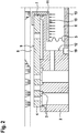
- the Fig. 2 is a modification of the metering valve 1 of Fig. 1 refer to.
- the corrugated bellows 5 is completely received in a central recess 12 of the valve seat element 2 and is firmly connected to the valve seat element 2 via a plate 13 and a fastening element 19.
- the advantages of fixing the corrugated bellows 5 on both sides are described below in connection with the exemplary embodiment of FIG Figures 3a and 3b which shows a similar example.
- a closing force acting on the closing element 4 can be seen, which presses the closing element 4 in the direction of the valve seat element 2.
- This closing force is at least partially compensated for by a counterforce which acts indirectly on the closing element 4 via a pressure surface 10 formed on a flange component 11.
- the flange component 11 is firmly connected to the closing element 4 on the one hand and to the corrugated bellows 5 on the other hand. It passes through the central recess 7 formed in the closing element 4. Since the same gas pressure prevails in the compensation chamber 6 and in the pressure chamber 8, the amount of compensation is determined by the area ratio of the two pressure surfaces 9, 10.
- Fig. 3a shows the operating principle of the compensation via the corrugated bellows 5 in the case of a closing force acting on the closing element 4.
- Figure 3b shows a compensation in the opposite direction, that is, with a pneumatic pressure force which acts on the closing element 4 in the opening direction.
- at least partial compensation is achieved if the corrugated bellows 5 is fixed directly or indirectly to the valve seat element 2 or a housing part at its end facing away from the closing element 4.
Landscapes
- Engineering & Computer Science (AREA)
- General Engineering & Computer Science (AREA)
- Chemical & Material Sciences (AREA)
- Mechanical Engineering (AREA)
- Oil, Petroleum & Natural Gas (AREA)
- General Chemical & Material Sciences (AREA)
- Chemical Kinetics & Catalysis (AREA)
- Combustion & Propulsion (AREA)
- Analytical Chemistry (AREA)
- Magnetically Actuated Valves (AREA)
- Measuring Volume Flow (AREA)
- Fluid-Driven Valves (AREA)
- Lift Valve (AREA)
Description
- Die Erfindung betrifft ein Dosierventil für einen gasförmigen Brennstoff mit den Merkmalen des Anspruchs 1.
- Bevorzugter Einsatzbereich des vorgeschlagenen Dosierventils ist die Brennstoffversorgung einer Verbrennungskraftmaschine, wobei es sich insbesondere um einen Gasmotor oder einen Gas-Diesel-Motor eines Fahrzeugs, beispielsweise eines Personenkraftfahrzeugs, eines Nutzfahrzeugs, eines Schienenfahrzeugs oder eines Schiffs handeln kann. Neben mobilen Anwendungen ist auch der Einsatz des Dosierventils in stationären Anlagen zur Energiegewinnung oder Energieerzeugung vorstellbar.
- Aus der Offenlegungsschrift
DE 10 2009 002 836 A1 ist ein Gasventil, insbesondere ein Dosierventil für ein gasförmiges Medium, bekannt, das ein plattenförmiges Ventilsitzelement und einen in Bezug auf das Ventilsitzelement hubbeweglichen Schließkörper zum Freigeben und Verschließen einer im Ventilsitzelement ausgebildeten Durchströmöffnung aufweist. Der Schließkörper wirkt dabei mit einem ringförmigen Dichtsitz des Ventilsitzelements zusammen, gegen den der Schließkörper mittels der Federkraft einer Feder axial vorgespannt ist. Das Öffnen des Gasventils wird mittels eines Elektromagneten bewirkt. Um eine möglichst exakte Brennstoffdosierung bei wechselnden Druckverhältnissen zu gewährleisten, ist das Gasventil druckausgeglichen ausgeführt. Der Schließkörper ist hierzu mit einer flexiblen Trennwand in Form eines Wellbalgs verbunden, der gemeinsam mit dem Schließkörper einen zulaufseitig angeordneten Rückraum begrenzt. Der zulaufseitige Rückraum ist über einen im Schließkörper ausgebildeten Verbindungskanal mit der Abströmseite des Gasventils verbunden, so dass auf beiden Seiten des Schließkörpers der gleiche Gasdruck herrscht. Die flexible Trennwand ist zudem in der Weise am Schließkörper festgelegt, dass ein den Rückraum begrenzender Oberflächenabschnitt auf der einen Seite des Schließkörpers annähernd gleich groß ist wie ein von dem Dichtsitz eingegrenzter Oberflächenabschnitt auf der dem Ventilsitzelement zugekehrten anderen Seite des Schließkörpers. In Öffnungs- und in Schließrichtung wirken demnach gleich große Axialkräfte, so dass sich diese gegenseitig in ihrer Wirkung auf den Schließkörper aufheben. Der Ventilhub beim Öffnen des Gasventils ist somit unabhängig von den im Gasventil vorherrschenden Druckverhältnissen - Weitere druckausgeglichene Ventile sind aus
DE 10 2014 212320 A1 ,US 4442998 A undUS 4240266 A bekannt. - Der vorliegenden Erfindung liegt die Aufgabe zugrunde, ein Dosierventil für ein gasförmiges Medium anzugeben, das eine Kompensation einer auf Druckdifferenzen zurückzuführenden pneumatischen Schließkraft ermöglicht und zudem besonders kompaktbauend ist. Die Kompensation der pneumatischen Schließkraft soll dazu beitragen, dass ein effizienteres und kostengünstigeres Aktordesign realisiert werden kann.
- Zur Lösung der Aufgabe wird das Dosierventil mit den Merkmalen des Anspruchs 1 vorgeschlagen. Vorteilhafte Weiterbildungen der Erfindung sind den Unteransprüchen zu entnehmen.
- Das vorgeschlagene Dosierventil umfasst ein plattenförmiges Ventilsitzelement mit mindestens einer Durchströmöffnung für den gasförmigen Brennstoff, ein dichtend mit dem Ventilsitzelement zusammenwirkendes, hubbewegliches Schließelement zum Freigeben und Verschließen der mindestens einen Durchströmöffnung und einen einen Kompensationsraum (6) begrenzenden und mit dem Schließelement verbundenen Well- oder Faltenbalg. Der Kompensationsraum ist über eine im Schließelement ausgebildete Ausnehmung mit einem Druckraum verbunden, so dass unabhängig von der Schaltstellung des Dosierventils in beiden Räumen der gleiche Gasdruck herrscht, wobei bei geöffnetem Dosierventil gasförmiger Brennstoff aus dem Druckraum über die mindestens eine Durchströmöffnung abströmt.
- Erfindungsgemäß ist der Kompensationsraum auf der dem Ventilsitzelement zugewandten Seite des Schließelements angeordnet und wird in axialer Richtung von einer Druckfläche begrenzt, die am Schließelement oder an einem mit dem Schließelement verbundenen Flanschbauteil, ausgebildet ist.
- Bei einem Anstieg des Gasdrucks im Druckraum, steigt gleichzeitig der Gasdruck im Kompensationsraum an. Dies führt zu einer unmittelbar oder mittelbar auf das Schließelement wirkenden pneumatischen Druckkraft, die - aufgrund der Lage des Kompensationsraums - in Öffnungsrichtung wirkt. Das heißt, dass über den Kompensationsraum eine Gegenkraft zu einer in Schließrichtung wirkenden pneumatischen Kraft erzeugbar ist, die zu einer teilweisen oder vollständigen Aufhebung der Schließkraft führt.
- Das Maß der Kompensation hängt vom Flächenverhältnis der in diesem Zusammenhang relevanten Flächen ab. Hierbei handelt es sich zum Einen um die unmittelbar oder mittelbar am Schließelement ausgebildete Druckfläche zur Begrenzung des Kompensationsraums. Zum Anderen um eine am Schließelement ausgebildete Druckfläche, die auf der dem Kompensationsraum abgewandten Seite des Schließelements ausgebildet bzw. dem Druckraum zugewandt ist. Das Flächenverhältnis entscheidet, ob die über den Druckraum indizierte, schließend wirkende pneumatische Druckkraft reduziert, ausgeglichen oder sogar überschritten wird, um eine zusätzliche öffnend wirkende Kraft zu erzeugen.
- Vorzugsweise wird über die Kompensationswirkung ein vollständiger Druckausgleich bewirkt, so dass ein druckausgeglichenes Dosierventil bzw. ein Dosierventil mit einem druckausgeglichenen Schließelement geschaffen wird. Dies hat den Vorteil, dass zum Einen die zum Öffnen erforderliche Öffnungskraft gering ist, zum Anderen das Dosierventil sicher schließt.
- Die Erfindung besitzt ferner den Vorteil, dass bei Einsatz des gleichen Standardmagneten größere Ventilbaugruppen realisierbar sind. Alternativ kann die Ventilgröße beibehalten werden, so dass höhere maximal schaltbare Druckdifferenzen möglich sind. In jedem Fall vergrößert sich der Anwendungsbereich eines Standard- bzw. Serienmagneten, so dass ein effizientes und kostengünstiges Aktorkonzept zur Verfügung gestellt wird.
- Gemäß einer bevorzugten Ausführungsform der Erfindung ist das Schließelement im Wesentlichen plattenförmig ausgeführt. Die Plattenform des Schließelements ermöglicht eine besonders kompakt bauende Anordnung, insbesondere in axialer Richtung, so dass der Bauraumbedarf des Dosierventils gesenkt werden kann. Um ein gleichmäßiges Anströmen der mindestens einen im Ventilsitzelement ausgebildeten Durchströmöffnung bei geöffnetem Dosierventil zu ermöglichen, wird vorgeschlagen, dass im plattenförmigen Schließelement ebenfalls mindestens eine Durchströmöffnung angeordnet ist, die versetzt zur Durchströmöffnung des Ventilsitzelements angeordnet ist.
- Alternativ oder ergänzend wird vorgeschlagen, dass das vorzugsweise plattenförmige Schließelement auf der dem Ventilsitzelement abgewandten Seite eine dem Druckraum zugewandte Druckfläche aufweist. Das heißt, dass das Schließelement über die Druckfläche angeströmt wird. In Abhängigkeit von der Größe der dem Druckraum zugewandten Druckfläche kann dann - ja nach zu erreichendem Kompensationsgrad - die Größe der den Kompensationsraum begrenzenden Druckfläche gewählt werden.
- Des Weiteren bevorzugt durchgreift bzw. durchgreifen das Schließelement und/oder das mit dem Schließelement verbundene Bauteil das Ventilsitzelement. Beispielsweise kann das Schließelement einen kragenförmigen Ansatz aufweisen, der durch eine Ausnehmung des Ventilsitzelements geführt ist, um die notwendige Verbindung des Schließelements mit dem Well- oder Faltenbalg herzustellen. Um die Montage zu vereinfachen, kann das Schließelement auch mehrteilig ausgeführt sein bzw. mit einem weiteren Bauteil, insbesondere einem Flanschbauteil, verbunden sein. Der kragenförmige Ansatz bzw. das Flanschbauteil ermöglichen die Ausbildung einer ausreichend großen Druckfläche, so dass sichergestellt ist, dass die hierüber erzeugte Gegenkraft groß genug ist, um die gewünschte Kompensation zu erreichen.
- Vorteilhafterweise ist der der Begrenzung des Kompensationsraums dienende Well- oder Faltenbalg zumindest abschnittsweise in einer zentralen Ausnehmung des Ventilsitzelements aufgenommen. Dadurch kann weiterhin Bauraum eingespart werden.
- Ferner wird vorgeschlagen, dass der Well- oder Faltenbalg an seinem dem Schließelement abgewandten Ende mit einer den Kompensationsraum begrenzenden Platte verbunden ist. Die Platte dichtet den Kompensationsraum gegen die Umgebung ab.
- Um sicherzustellen, dass ein Anstieg des Gasdrucks im Kompensationsraum zu einer auf das Schließelement in Öffnungsrichtung wirkenden pneumatischen Druckkraft führt, wird vorgeschlagen, dass der Well- oder Faltenbalg an seinem dem Schließelement abgewandten Ende unmittelbar oder mittelbar über die Platte an einer Anschlagfläche axial abgestützt ist. Die Anschlagfläche kann beispielsweise durch das Ventilsitzelement oder ein mit dem Ventilsitzelement verbundenes Anschlagelement ausgebildet werden.
- In Weiterbildung der Erfindung wird vorgeschlagen, dass der Well- oder Faltenbalg an seinem dem Schließelement abgewandten Ende unmittelbar oder mittelbar über die Platte mit dem Ventilsitzelement fest verbunden ist. Auf diese Weise wird eine in zwei Richtungen wirksame Kompensationseinrichtung geschaffen. Das heißt, dass nicht nur eine Gegenkraft zu einer in Schließrichtung wirkenden pneumatischen Druckkraft erzeugbar ist, sondern ferner eine Gegenkraft zu einer in Öffnungsrichtung auf das Schließelement wirkenden pneumatischen Druckkraft. Ein "doppelt wirkender" Well- oder Faltenbalg hält zudem höheren Gegendrücken stand, ohne das Ventil zu öffnen.
- Vorausgesetzt, dass der Well- oder Faltenbalg doppelt wirkt, kann dieser zugleich ein Federelement ausbilden, das axial vorspannbar oder axial vorgespannt ist. Der doppelt wirkende Well- oder Faltenbalg macht somit den Verzicht auf eine oder mehrere Rückstellfedern zur Rückstellung des Schließelements möglich. Die Federsteifigkeit des Well- oder Faltenbalgs wird dabei durch seine geometrischen Abmessungen beeinflusst. Ist die prinzipielle Geometrie des Well- oder Faltenbalgs aufgrund der Anforderungen (mechanische Belastbarkeit, Drücke und dergleichen) festgelegt, kann die Federsteifigkeit über die Anzahl der Wellen bzw. Falten verändert werden.
- Bevorzugt sind die den Kompensationsraum begrenzende Druckfläche und die dem Druckraum zugewandte Druckfläche des Schließelements in radialer Richtung zumindest teilweise überlappend angeordnet. Das heißt, dass in radialer Richtung die über den Kompensationsraum erzeugte Gegenkraft im Bereich der zu kompensierenden pneumatischen Druckkraft angreift. Auf diese Weise wird eine Biegebeanspruchung des Schließelements vermieden, so dass dieses beispielsweise als dünnes Plättchen ausgebildet werden kann.
- Darüber hinaus wird vorgeschlagen, dass ein Elektromagnet zur Einwirkung auf einen mit dem Schließelement verbundenen oder durch das Schließelement ausgebildeten
- Anker vorgesehen ist. Das erfindungsgemäße Dosierventil ist demnach bevorzugt elektromagnetisch betätigbar, wobei weiterhin bevorzugt ein Standard- bzw. Serienmagnet zum Einsatz gelangt. Bei einer Bestromung des Elektromagneten baut sich ein Magnetfeld auf, das eine auf den Anker einwirkende Magnetkraft erzeugt. Der Anker bewegt sich in Richtung des Elektromagneten. Ist der Anker als ein eigenständiges Bauteil ausgeführt ist, das mit dem Schließelement verbunden ist, führt er das Schließelement mit, so dass dieses vom Ventilsitzelement abhebt und die mindestens eine Durchströmöffnung freigibt. Bildet das Schließelement zugleich den Anker aus, wird das Schließelement durch die Magnetkraft in Richtung des Elektromagneten gezogen. Die integrierte Ankerfunktion des Schließelements führt zu einer besonders kompakt bauenden Bauform eines erfindungsgemäßen Dosierventils.
- Bevorzugte Ausführungsformen der Erfindung werden nachfolgend anhand der beigefügten Zeichnungen näher erläutert. Diese zeigen:
-
Fig. 1 einen schematischen Längsschnitt durch ein erfindungsgemäßes Dosierventil gemäß einer ersten bevorzugten Ausführungsform, -
Fig. 2 einen schematischen Längsschnitt durch ein erfindungsgemäßes Dosierventil gemäß einer zweiten bevorzugten Ausführungsform, -
Fig. 3a und 3b einen schematischen Längsschnitt durch ein erfindungsgemäßes Dosierventil gemäß einer dritten bevorzugten Ausführungsform und -
Fig. 4a und 4b einen schematischen Längsschnitt durch ein erfindungsgemäßes Dosierventil gemäß einer vierten bevorzugten Ausführungsform. - Das in der
Fig. 1 dargestellte Dosierventil 1 dient dem Eindosieren eines gasförmigen Brennstoffs in einen Ansaugtrakt einer Verbrennungskraftmaschine. Es umfasst ein zumindest abschnittsweise hohlzylinderförmiges Gehäuseteil 18, in das ein plattenförmiges Ventilsitzelement 2 mit mehreren konzentrisch angeordneten, kreisbogenförmigen Durchströmöffnungen 3 eingesetzt ist. Oberhalb des Ventilsitzelements 2 ist ein als dünnes Plättchen ausgebildetes, hubbewegliches Schließelement 4 angeordnet, das in Schließstellung die Durchströmöffnungen 3 verschließt. Über Federn 17 ist da Schließelement 4 gegen das Ventilsitzelement 2 axial vorgespannt. - Das plättchenförmige Schließelement 4 bildet vorliegend zugleich einen Anker 16 aus, so dass Bauraum eingespart wird. Zur Einwirkung auf den Anker 17 bzw. das Schließelement 4 ist ein Elektromagnet 15 vorgesehen, der oberhalb des Schließelements 4 angeordnet ist. Wird der Elektromagnet 15 bestromt, bewegt sich das Schließelement 4 entgegen der Federkraft der Federn 17 in Richtung des Elektromagneten 15 und das Dosierventil 1 öffnet. Über die Durchströmöffnungen 3 strömt somit gasförmiger Brennstoff aus einem Druckraum 8 ab. Wird die Bestromung des Elektromagneten 15 beendet, stellen die Federn 17 das Schließelement 4 in seine Ausgangslage zurück.
- Das Schließelement 4 weist eine dem Druckraum 8 zugewandte Druckfläche 9 auf, an welcher der im Druckraum 8 vorherrschende Gasdruck anliegt. Steigt bei geschlossenem Dosierventil 1 der Gasdruck im Druckraum 8 an, führt dies zu Druckdifferenzen, die eine auf das Schließelement 4 in Schließrichtung wirkende pneumatische Drucckraft zur Folge hat. Damit steigt die zum Öffnen des Dosierventils 1 erforderliche Öffnungskraft, so dass ggf. die Magnetkraft des Elektromagneten 15 nicht mehr ausreicht.
- Um dies zu verhindern, weist das dargestellte erfindungsgemäße Dosierventil 1 einen Kompensationsraum 6 auf, der auf der dem Druckraum 8 abgewandten Seite des Schließelements 4 angeordnet und über eine im Schließelement 4 ausgebildete zentrale Ausnehmung 7 mit dem Druckraum 8 verbunden ist. Im Kompensationsraum 6 herrscht somit der gleiche Gasdruck wie im Druckraum 8. Der Kompensationsraum 6 wird in radialer Richtung von einem Wellbalg 5 begrenzt, der über eine Bauteil 11 in Form eines Flanschbauteils fest mit dem Schließelement 4 verbunden ist. Dies hat zur Folge, dass über eine am Flanschbauteil ausgebildete Druckfläche 10 eine in Öffnungsrichtung auf das Schließelement 4 wirkende pneumatische Druckkraft bewirkbar ist, die eine Gegenkraft zur Schließkraft darstellt. Denn andernends ist der Wellbalg 5 über eine Platte 13 an einer Anschlagfläche 14 eines Anschlagelements 20 abgestützt, das mittels eines Befestigungselements 19 mit dem Ventilsitzelement 2 fest verbunden ist. Steigt der Gasdruck im Kompensationsraum 6 entsprechend dem Gasdruck im Druckraum 8 an, wird eine zumindest teilweise Kompensation der auf das Schließelement 4 wirkenden pneumatischen Kräfte bewirkt. Das Maß der Kompensation hängt dabei vom Flächenverhältnis der Druckflächen 9, 10 ab.
- Der
Fig. 2 ist eine Abwandlung des Dosierventils 1 derFig. 1 zu entnehmen. Der Wellbalg 5 ist in diesem Beispiel vollständig in einer zentralen Ausnehmung 12 des Ventilsitzelements 2 aufgenommen und über eine Platte 13 und ein Befestigungselement 19 fest mit dem Ventilsitzelement 2 verbunden. Die Vorteile einer beidseitigen Fixierung des Wellbalgs 5 werden nachfolgend in Zusammenhang mit dem Ausführungsbeispiel derFiguren 3a und 3b erläutert, das ein ähnliches Beispiel zeigt. - Der
Fig. 2 ist eine auf das Schließelement 4 wirkende Schließkraft zu entnehmen, die das Schließelement 4 in Richtung des Ventilsitzelements 2 drückt. Diese Schließkraft wird zumindest in Teilen durch eine Gegenkraft kompensiert, die mittelbar über eine an einem Flanschbauteil 11 ausgebildete Druckfläche 10 auf das Schließelement 4 wirkt. Das Flanschbauteil 11 ist hierzu einerseits mit dem Schließelement 4, andererseits mit dem Wellbalg 5 fest verbunden. Dabei durchgreift es die im Schließelement 4 ausgebildete zentrale Ausnehmung 7. Da im Kompensationsraum 6 und im Druckraum 8 der gleiche Gasdruck herrscht, wird das Maß der Kompensation über das Flächenverhältnis der beiden Druckflächen 9, 10 bestimmt. - Das Ausführungsbeispiel der
Figuren 3a und 3b ist im Wesentlichen gleich dem derFig. 2 ausgeführt. Ein Unterschied besteht lediglich in der Befestigung der Platte 13 am Ventilsitzelement 2. -
Fig. 3a zeigt das Wirkprinzip der Kompensation über den Wellbalg 5 bei einer auf das Schließelement 4 wirkenden Schließkraft.Fig. 3b zeigt eine Kompensation in umgekehrter Richtung, das heißt bei eine pneumatischen Druckkraft, die in Öffnungsrichtung auf das Schließelement 4 wirkt. Denn auch in diesem Fall wird eine zumindest teilweise Kompensation erreicht, sofern der Wellbalg 5 an seinem dem Schließelement 4 abgewandten Ende unmittelbar oder mittelbar am Ventilsitzelement 2 oder einem Gehäuseteil fixiert ist. - Erfolgt eine solche Fixierung nicht, wie beispielshaft in den
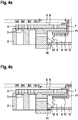
Figuren 4a und 4b dargestellt, kann zwar eine Kompensation der Schließkraft bewirkt werden (Fig. 4a ), nicht jedoch eine Kompensation einer Öffnungskraft, da in diesem Fall die Platte 13 von der Anschlagfläche 14 abhebt (Fig. 4b ).
Claims (10)
- Dosierventil (1) für einen gasförmigen Brennstoff, umfassend ein plattenförmiges Ventilsitzelement (2) mit mindestens einer Durchströmöffnung (3) für den gasförmigen Brennstoff, ein dichtend mit dem Ventilsitzelement (2) zusammenwirkendes, hubbewegliches Schließelement (4) zum Freigeben und Verschließen der mindestens einen Durchströmöffnung (3) und einen einen Kompensationsraum (6) begrenzenden und mit dem Schließelement (4) verbundenen Well- oder Faltenbalg (5), der über eine im Schließelement (4) ausgebildete Ausnehmung (7) mit einem Druckraum (8) verbunden ist, so dass unabhängig von der Schaltstellung des Dosierventils (1) im Kompensationsraum (6) und im Druckraum (8) der gleiche Gasdruck herrscht, wobei bei geöffnetem Dosierventil (1) gasförmiger Brennstoff aus dem Druckraum (8) über die mindestens eine Durchströmöffnung (3) abströmt,
dadurch gekennzeichnet, dass der Kompensationsraum (6) auf der dem Ventilsitzelement (2) zugewandten Seite des Schließelements (4) angeordnet ist und in axialer Richtung von einer Druckfläche (10) begrenzt wird, die am Schließelement (4) oder an einem mit dem Schließelement (4) verbundenen Flanschbauteil (11) ausgebildet ist. - Dosierventil (1) nach Anspruch 1,
dadurch gekennzeichnet, dass das Schließelement (4) im Wesentlichen plattenförmig ausgeführt ist und/oder auf der dem Ventilsitzelement (2) abgewandten Seite eine dem Druckraum (8) zugewandte Druckfläche (9) aufweist. - Dosierventil (1) nach Anspruch 1 oder 2,
dadurch gekennzeichnet, dass das Schließelement (4) und/oder das mit dem Schließelement (4) verbundene Bauteil (11) das Ventilsitzelement (2) durchgreift bzw. durchgreifen. - Dosierventil (1) nach einem der vorhergehenden Ansprüche,
dadurch gekennzeichnet, dass der Well- oder Faltenbalg (5) zumindest abschnittsweise in einer zentralen Ausnehmung (12) des Ventilsitzelements (2) aufgenommen ist. - Dosierventil (1) nach einem der vorhergehenden Ansprüche,
dadurch gekennzeichnet, dass der Well- oder Faltenbalg (5) an seinem dem Schließelement (4) abgewandten Ende mit einer den Kompensationsraum (6) begrenzenden Platte (13) verbunden ist. - Dosierventil (1) nach Anspruch 5,
dadurch gekennzeichnet, dass der Well- oder Faltenbalg (5) an seinem dem Schließelement (4) abgewandten Ende unmittelbar oder mittelbar über die Platte (13) an einer Anschlagfläche (14) axial abgestützt ist. - Dosierventil (1) nach Anspruch 5,
dadurch gekennzeichnet, dass der Well- oder Faltenbalg (5) an seinem dem Schließelement (4) abgewandten Ende unmittelbar oder mittelbar über die Platte (13) mit dem Ventilsitzelement (2) fest verbunden ist. - Dosierventil (1) nach einem der Ansprüche 2 bis 7,
dadurch gekennzeichnet, dass der Well- oder Faltenbalg (5) ein axial vorspannbares oder axial vorgespanntes Federelement ausbildet. - Dosierventil (1) nach einem der vorhergehenden Ansprüche,
dadurch gekennzeichnet, dass die den Kompensationsraum (6) begrenzende Druckfläche (10) und die dem Druckraum (8) zugewandte Druckfläche (9) des Schließelements (4) in radialer Richtung zumindest teilweise überlappend angeordnet sind. - Dosierventil (1) nach einem der vorhergehenden Ansprüche,
dadurch gekennzeichnet, dass ein Elektromagnet (15) zur Einwirkung auf einen mit dem Schließelement (4) verbundenen oder durch das Schließelement (4) ausgebildeten Anker (16) vorgesehen ist.
Applications Claiming Priority (2)
| Application Number | Priority Date | Filing Date | Title |
|---|---|---|---|
| DE102017212756.2A DE102017212756A1 (de) | 2017-07-25 | 2017-07-25 | Dosierventil für ein gasförmiges Medium |
| PCT/EP2018/069491 WO2019020452A1 (de) | 2017-07-25 | 2018-07-18 | Dosierventil für ein gasförmiges medium |
Publications (2)
| Publication Number | Publication Date |
|---|---|
| EP3658764A1 EP3658764A1 (de) | 2020-06-03 |
| EP3658764B1 true EP3658764B1 (de) | 2021-05-05 |
Family
ID=62952096
Family Applications (1)
| Application Number | Title | Priority Date | Filing Date |
|---|---|---|---|
| EP18742790.1A Active EP3658764B1 (de) | 2017-07-25 | 2018-07-18 | Dosierventil für einen gasförmigen brennstoff |
Country Status (5)
| Country | Link |
|---|---|
| US (1) | US11156189B2 (de) |
| EP (1) | EP3658764B1 (de) |
| JP (1) | JP6894577B2 (de) |
| DE (1) | DE102017212756A1 (de) |
| WO (1) | WO2019020452A1 (de) |
Family Cites Families (12)
| Publication number | Priority date | Publication date | Assignee | Title |
|---|---|---|---|---|
| GB1579662A (en) * | 1977-04-29 | 1980-11-19 | Shipowners Cargo Res Assoc | Refrigeration control systems |
| US4442998A (en) | 1979-07-24 | 1984-04-17 | Aisin Seiki Kabushiki Kaisha | Electromagnetic valve unit |
| US4971104A (en) * | 1990-02-28 | 1990-11-20 | Sundstrand Corporation | Self powered servo actuated backpressure regulating valve |
| AU3134597A (en) * | 1996-05-20 | 1997-12-09 | Borg-Warner Automotive, Inc. | Automotive fluid control system with pressure balanced solenoid valve |
| JP3719566B2 (ja) * | 1996-05-27 | 2005-11-24 | 株式会社デンソー | 電磁弁 |
| US6328054B1 (en) * | 2000-07-07 | 2001-12-11 | Parker-Hannifin Corporation-Veriflo Division | Balanced fluid pressure regulator |
| US6505812B1 (en) | 2000-11-17 | 2003-01-14 | Mks Instruments, Inc. | Solenoid valve |
| WO2006111987A1 (en) | 2005-04-19 | 2006-10-26 | Omvl S.P.A. | A gaseous fuel injector for internal combustion engines |
| US8272399B2 (en) * | 2008-06-13 | 2012-09-25 | Woodward, Inc. | Fluid admission system for providing a pressure-balanced valve |
| DE102009002836A1 (de) | 2009-05-06 | 2010-11-11 | Robert Bosch Gmbh | Gasventil |
| DE102013212681A1 (de) * | 2013-06-28 | 2014-12-31 | Robert Bosch Gmbh | Magnetventil und Verfahren zur Herstellung von Magnetventilen |
| DE102014212320A1 (de) * | 2014-06-26 | 2015-12-31 | Robert Bosch Gmbh | Gasventil |
-
2017
- 2017-07-25 DE DE102017212756.2A patent/DE102017212756A1/de not_active Withdrawn
-
2018
- 2018-07-18 WO PCT/EP2018/069491 patent/WO2019020452A1/de not_active Ceased
- 2018-07-18 JP JP2020501450A patent/JP6894577B2/ja active Active
- 2018-07-18 EP EP18742790.1A patent/EP3658764B1/de active Active
- 2018-07-18 US US16/634,217 patent/US11156189B2/en active Active
Also Published As
| Publication number | Publication date |
|---|---|
| JP2020527207A (ja) | 2020-09-03 |
| WO2019020452A1 (de) | 2019-01-31 |
| US11156189B2 (en) | 2021-10-26 |
| US20210088004A1 (en) | 2021-03-25 |
| JP6894577B2 (ja) | 2021-06-30 |
| DE102017212756A1 (de) | 2019-01-31 |
| EP3658764A1 (de) | 2020-06-03 |
Similar Documents
| Publication | Publication Date | Title |
|---|---|---|
| EP1762712B1 (de) | Bypassventil für Verbrennungskraftmaschinen | |
| EP3123021A1 (de) | Elektromagnetisch betätigbares gasventil sowie verfahren zur erhöhung der dichtigkeit eines elektromagnetisch betätigbaren gasventils | |
| EP1771653B1 (de) | Ventil für den einsatz in einer kraftstoffführenden leitung eines kraftfahrzeuges | |
| EP1062420B1 (de) | Ventil zum dosierten einleiten von verflüchtigtem brennstoff | |
| DE102010039052A1 (de) | Eisddruckfeste Einspritzvorrichtung | |
| EP1373704B1 (de) | Magnetventil | |
| EP3286424B1 (de) | Gasventil | |
| EP3280901B1 (de) | Gasventil | |
| EP1458999B1 (de) | Elektromagnetisches tankentlüftungsventil | |
| DE102014208397A1 (de) | Ventil zum Steuern eines gasförmigen Mediums | |
| DE102016123738A1 (de) | Klappenvorrichtung | |
| EP2603680A1 (de) | Einspritzvorrichtung zum einbringen einer harnstofflösung in den abgasstrang einer brennkraftmaschine | |
| DE19814744A1 (de) | Druckregelventil | |
| DE112020000261T5 (de) | Metalldämpfer mit Metallmembran und damit versehene Kraftstoffpumpe | |
| WO2019020452A1 (de) | Dosierventil für ein gasförmiges medium | |
| EP3662155B1 (de) | Verfahren zur herstellung eines dosierventils, dosierventil | |
| DE102009015184A1 (de) | Klappenventil | |
| EP1208321A1 (de) | Ventil zum steuern von flüssigkeiten | |
| DE102007056891A1 (de) | Kraftstoff-Hochdruckpumpe für ein Kraftstoffsystem einer Brennkraftmaschine | |
| DE202005013233U1 (de) | Magnetventil-System | |
| WO2016102256A1 (de) | Ventil zur steuerung eines gasstroms, flüssigkeitsabscheider, entlüftungssystem und verbrennungsmotor mit einem derartigen ventil | |
| DE102010062077A1 (de) | Ventileinrichtung mit einem wenigstens abschnittsweise zylindrischen Bewegungselement | |
| EP3497317A1 (de) | Elektromagnetisch betätigbares ventil zum einblasen von gas | |
| DE102017222501A1 (de) | Ventil zum Zumessen eines Fluids | |
| DE102013224960A1 (de) | Kraftstoffinjektor |
Legal Events
| Date | Code | Title | Description |
|---|---|---|---|
| STAA | Information on the status of an ep patent application or granted ep patent |
Free format text: STATUS: UNKNOWN |
|
| STAA | Information on the status of an ep patent application or granted ep patent |
Free format text: STATUS: THE INTERNATIONAL PUBLICATION HAS BEEN MADE |
|
| PUAI | Public reference made under article 153(3) epc to a published international application that has entered the european phase |
Free format text: ORIGINAL CODE: 0009012 |
|
| STAA | Information on the status of an ep patent application or granted ep patent |
Free format text: STATUS: REQUEST FOR EXAMINATION WAS MADE |
|
| 17P | Request for examination filed |
Effective date: 20200225 |
|
| AK | Designated contracting states |
Kind code of ref document: A1 Designated state(s): AL AT BE BG CH CY CZ DE DK EE ES FI FR GB GR HR HU IE IS IT LI LT LU LV MC MK MT NL NO PL PT RO RS SE SI SK SM TR |
|
| AX | Request for extension of the european patent |
Extension state: BA ME |
|
| DAV | Request for validation of the european patent (deleted) | ||
| DAX | Request for extension of the european patent (deleted) | ||
| GRAP | Despatch of communication of intention to grant a patent |
Free format text: ORIGINAL CODE: EPIDOSNIGR1 |
|
| STAA | Information on the status of an ep patent application or granted ep patent |
Free format text: STATUS: GRANT OF PATENT IS INTENDED |
|
| INTG | Intention to grant announced |
Effective date: 20201214 |
|
| GRAS | Grant fee paid |
Free format text: ORIGINAL CODE: EPIDOSNIGR3 |
|
| GRAA | (expected) grant |
Free format text: ORIGINAL CODE: 0009210 |
|
| STAA | Information on the status of an ep patent application or granted ep patent |
Free format text: STATUS: THE PATENT HAS BEEN GRANTED |
|
| AK | Designated contracting states |
Kind code of ref document: B1 Designated state(s): AL AT BE BG CH CY CZ DE DK EE ES FI FR GB GR HR HU IE IS IT LI LT LU LV MC MK MT NL NO PL PT RO RS SE SI SK SM TR |
|
| REG | Reference to a national code |
Ref country code: GB Ref legal event code: FG4D Free format text: NOT ENGLISH |
|
| REG | Reference to a national code |
Ref country code: CH Ref legal event code: EP |
|
| REG | Reference to a national code |
Ref country code: AT Ref legal event code: REF Ref document number: 1390098 Country of ref document: AT Kind code of ref document: T Effective date: 20210515 |
|
| REG | Reference to a national code |
Ref country code: NL Ref legal event code: FP |
|
| REG | Reference to a national code |
Ref country code: IE Ref legal event code: FG4D Free format text: LANGUAGE OF EP DOCUMENT: GERMAN |
|
| REG | Reference to a national code |
Ref country code: DE Ref legal event code: R096 Ref document number: 502018005169 Country of ref document: DE |
|
| REG | Reference to a national code |
Ref country code: LT Ref legal event code: MG9D |
|
| PG25 | Lapsed in a contracting state [announced via postgrant information from national office to epo] |
Ref country code: BG Free format text: LAPSE BECAUSE OF FAILURE TO SUBMIT A TRANSLATION OF THE DESCRIPTION OR TO PAY THE FEE WITHIN THE PRESCRIBED TIME-LIMIT Effective date: 20210805 Ref country code: HR Free format text: LAPSE BECAUSE OF FAILURE TO SUBMIT A TRANSLATION OF THE DESCRIPTION OR TO PAY THE FEE WITHIN THE PRESCRIBED TIME-LIMIT Effective date: 20210505 Ref country code: LT Free format text: LAPSE BECAUSE OF FAILURE TO SUBMIT A TRANSLATION OF THE DESCRIPTION OR TO PAY THE FEE WITHIN THE PRESCRIBED TIME-LIMIT Effective date: 20210505 Ref country code: FI Free format text: LAPSE BECAUSE OF FAILURE TO SUBMIT A TRANSLATION OF THE DESCRIPTION OR TO PAY THE FEE WITHIN THE PRESCRIBED TIME-LIMIT Effective date: 20210505 |
|
| PG25 | Lapsed in a contracting state [announced via postgrant information from national office to epo] |
Ref country code: SE Free format text: LAPSE BECAUSE OF FAILURE TO SUBMIT A TRANSLATION OF THE DESCRIPTION OR TO PAY THE FEE WITHIN THE PRESCRIBED TIME-LIMIT Effective date: 20210505 Ref country code: PT Free format text: LAPSE BECAUSE OF FAILURE TO SUBMIT A TRANSLATION OF THE DESCRIPTION OR TO PAY THE FEE WITHIN THE PRESCRIBED TIME-LIMIT Effective date: 20210906 Ref country code: RS Free format text: LAPSE BECAUSE OF FAILURE TO SUBMIT A TRANSLATION OF THE DESCRIPTION OR TO PAY THE FEE WITHIN THE PRESCRIBED TIME-LIMIT Effective date: 20210505 Ref country code: NO Free format text: LAPSE BECAUSE OF FAILURE TO SUBMIT A TRANSLATION OF THE DESCRIPTION OR TO PAY THE FEE WITHIN THE PRESCRIBED TIME-LIMIT Effective date: 20210805 Ref country code: LV Free format text: LAPSE BECAUSE OF FAILURE TO SUBMIT A TRANSLATION OF THE DESCRIPTION OR TO PAY THE FEE WITHIN THE PRESCRIBED TIME-LIMIT Effective date: 20210505 Ref country code: PL Free format text: LAPSE BECAUSE OF FAILURE TO SUBMIT A TRANSLATION OF THE DESCRIPTION OR TO PAY THE FEE WITHIN THE PRESCRIBED TIME-LIMIT Effective date: 20210505 Ref country code: GR Free format text: LAPSE BECAUSE OF FAILURE TO SUBMIT A TRANSLATION OF THE DESCRIPTION OR TO PAY THE FEE WITHIN THE PRESCRIBED TIME-LIMIT Effective date: 20210806 Ref country code: IS Free format text: LAPSE BECAUSE OF FAILURE TO SUBMIT A TRANSLATION OF THE DESCRIPTION OR TO PAY THE FEE WITHIN THE PRESCRIBED TIME-LIMIT Effective date: 20210905 |
|
| PG25 | Lapsed in a contracting state [announced via postgrant information from national office to epo] |
Ref country code: CZ Free format text: LAPSE BECAUSE OF FAILURE TO SUBMIT A TRANSLATION OF THE DESCRIPTION OR TO PAY THE FEE WITHIN THE PRESCRIBED TIME-LIMIT Effective date: 20210505 Ref country code: DK Free format text: LAPSE BECAUSE OF FAILURE TO SUBMIT A TRANSLATION OF THE DESCRIPTION OR TO PAY THE FEE WITHIN THE PRESCRIBED TIME-LIMIT Effective date: 20210505 Ref country code: RO Free format text: LAPSE BECAUSE OF FAILURE TO SUBMIT A TRANSLATION OF THE DESCRIPTION OR TO PAY THE FEE WITHIN THE PRESCRIBED TIME-LIMIT Effective date: 20210505 Ref country code: SM Free format text: LAPSE BECAUSE OF FAILURE TO SUBMIT A TRANSLATION OF THE DESCRIPTION OR TO PAY THE FEE WITHIN THE PRESCRIBED TIME-LIMIT Effective date: 20210505 Ref country code: EE Free format text: LAPSE BECAUSE OF FAILURE TO SUBMIT A TRANSLATION OF THE DESCRIPTION OR TO PAY THE FEE WITHIN THE PRESCRIBED TIME-LIMIT Effective date: 20210505 Ref country code: ES Free format text: LAPSE BECAUSE OF FAILURE TO SUBMIT A TRANSLATION OF THE DESCRIPTION OR TO PAY THE FEE WITHIN THE PRESCRIBED TIME-LIMIT Effective date: 20210505 Ref country code: SK Free format text: LAPSE BECAUSE OF FAILURE TO SUBMIT A TRANSLATION OF THE DESCRIPTION OR TO PAY THE FEE WITHIN THE PRESCRIBED TIME-LIMIT Effective date: 20210505 |
|
| REG | Reference to a national code |
Ref country code: DE Ref legal event code: R097 Ref document number: 502018005169 Country of ref document: DE |
|
| REG | Reference to a national code |
Ref country code: CH Ref legal event code: PL |
|
| PLBE | No opposition filed within time limit |
Free format text: ORIGINAL CODE: 0009261 |
|
| STAA | Information on the status of an ep patent application or granted ep patent |
Free format text: STATUS: NO OPPOSITION FILED WITHIN TIME LIMIT |
|
| PG25 | Lapsed in a contracting state [announced via postgrant information from national office to epo] |
Ref country code: MC Free format text: LAPSE BECAUSE OF FAILURE TO SUBMIT A TRANSLATION OF THE DESCRIPTION OR TO PAY THE FEE WITHIN THE PRESCRIBED TIME-LIMIT Effective date: 20210505 |
|
| REG | Reference to a national code |
Ref country code: BE Ref legal event code: MM Effective date: 20210731 |
|
| 26N | No opposition filed |
Effective date: 20220208 |
|
| PG25 | Lapsed in a contracting state [announced via postgrant information from national office to epo] |
Ref country code: LI Free format text: LAPSE BECAUSE OF NON-PAYMENT OF DUE FEES Effective date: 20210731 Ref country code: CH Free format text: LAPSE BECAUSE OF NON-PAYMENT OF DUE FEES Effective date: 20210731 |
|
| PG25 | Lapsed in a contracting state [announced via postgrant information from national office to epo] |
Ref country code: IS Free format text: LAPSE BECAUSE OF FAILURE TO SUBMIT A TRANSLATION OF THE DESCRIPTION OR TO PAY THE FEE WITHIN THE PRESCRIBED TIME-LIMIT Effective date: 20210905 Ref country code: LU Free format text: LAPSE BECAUSE OF NON-PAYMENT OF DUE FEES Effective date: 20210718 Ref country code: FR Free format text: LAPSE BECAUSE OF NON-PAYMENT OF DUE FEES Effective date: 20210731 Ref country code: AL Free format text: LAPSE BECAUSE OF FAILURE TO SUBMIT A TRANSLATION OF THE DESCRIPTION OR TO PAY THE FEE WITHIN THE PRESCRIBED TIME-LIMIT Effective date: 20210505 |
|
| PG25 | Lapsed in a contracting state [announced via postgrant information from national office to epo] |
Ref country code: IT Free format text: LAPSE BECAUSE OF FAILURE TO SUBMIT A TRANSLATION OF THE DESCRIPTION OR TO PAY THE FEE WITHIN THE PRESCRIBED TIME-LIMIT Effective date: 20210505 Ref country code: IE Free format text: LAPSE BECAUSE OF NON-PAYMENT OF DUE FEES Effective date: 20210718 Ref country code: BE Free format text: LAPSE BECAUSE OF NON-PAYMENT OF DUE FEES Effective date: 20210731 |
|
| GBPC | Gb: european patent ceased through non-payment of renewal fee |
Effective date: 20220718 |
|
| PG25 | Lapsed in a contracting state [announced via postgrant information from national office to epo] |
Ref country code: GB Free format text: LAPSE BECAUSE OF NON-PAYMENT OF DUE FEES Effective date: 20220718 |
|
| PG25 | Lapsed in a contracting state [announced via postgrant information from national office to epo] |
Ref country code: CY Free format text: LAPSE BECAUSE OF FAILURE TO SUBMIT A TRANSLATION OF THE DESCRIPTION OR TO PAY THE FEE WITHIN THE PRESCRIBED TIME-LIMIT Effective date: 20210505 |
|
| PG25 | Lapsed in a contracting state [announced via postgrant information from national office to epo] |
Ref country code: HU Free format text: LAPSE BECAUSE OF FAILURE TO SUBMIT A TRANSLATION OF THE DESCRIPTION OR TO PAY THE FEE WITHIN THE PRESCRIBED TIME-LIMIT; INVALID AB INITIO Effective date: 20180718 |
|
| PG25 | Lapsed in a contracting state [announced via postgrant information from national office to epo] |
Ref country code: MK Free format text: LAPSE BECAUSE OF FAILURE TO SUBMIT A TRANSLATION OF THE DESCRIPTION OR TO PAY THE FEE WITHIN THE PRESCRIBED TIME-LIMIT Effective date: 20210505 |
|
| PG25 | Lapsed in a contracting state [announced via postgrant information from national office to epo] |
Ref country code: MT Free format text: LAPSE BECAUSE OF FAILURE TO SUBMIT A TRANSLATION OF THE DESCRIPTION OR TO PAY THE FEE WITHIN THE PRESCRIBED TIME-LIMIT Effective date: 20210505 |
|
| PGFP | Annual fee paid to national office [announced via postgrant information from national office to epo] |
Ref country code: NL Payment date: 20250723 Year of fee payment: 8 |
|
| PGFP | Annual fee paid to national office [announced via postgrant information from national office to epo] |
Ref country code: DE Payment date: 20250924 Year of fee payment: 8 |
|
| PGFP | Annual fee paid to national office [announced via postgrant information from national office to epo] |
Ref country code: AT Payment date: 20250721 Year of fee payment: 8 |
|
| PG25 | Lapsed in a contracting state [announced via postgrant information from national office to epo] |
Ref country code: TR Free format text: LAPSE BECAUSE OF FAILURE TO SUBMIT A TRANSLATION OF THE DESCRIPTION OR TO PAY THE FEE WITHIN THE PRESCRIBED TIME-LIMIT Effective date: 20210505 |