EP3657677A1 - Stromversorgungsschaltkreis für steuerschaltungen von schaltern - Google Patents
Stromversorgungsschaltkreis für steuerschaltungen von schaltern Download PDFInfo
- Publication number
- EP3657677A1 EP3657677A1 EP19209871.3A EP19209871A EP3657677A1 EP 3657677 A1 EP3657677 A1 EP 3657677A1 EP 19209871 A EP19209871 A EP 19209871A EP 3657677 A1 EP3657677 A1 EP 3657677A1
- Authority
- EP
- European Patent Office
- Prior art keywords
- circuit
- terminal
- switch
- switches
- series
- Prior art date
- Legal status (The legal status is an assumption and is not a legal conclusion. Google has not performed a legal analysis and makes no representation as to the accuracy of the status listed.)
- Pending
Links
Images


Classifications
-
- H—ELECTRICITY
- H02—GENERATION; CONVERSION OR DISTRIBUTION OF ELECTRIC POWER
- H02M—APPARATUS FOR CONVERSION BETWEEN AC AND AC, BETWEEN AC AND DC, OR BETWEEN DC AND DC, AND FOR USE WITH MAINS OR SIMILAR POWER SUPPLY SYSTEMS; CONVERSION OF DC OR AC INPUT POWER INTO SURGE OUTPUT POWER; CONTROL OR REGULATION THEREOF
- H02M1/00—Details of apparatus for conversion
- H02M1/44—Circuits or arrangements for compensating for electromagnetic interference in converters or inverters
-
- H—ELECTRICITY
- H03—ELECTRONIC CIRCUITRY
- H03K—PULSE TECHNIQUE
- H03K17/00—Electronic switching or gating, i.e. not by contact-making and –breaking
- H03K17/06—Modifications for ensuring a fully conducting state
- H03K17/063—Modifications for ensuring a fully conducting state in field-effect transistor switches
-
- H—ELECTRICITY
- H02—GENERATION; CONVERSION OR DISTRIBUTION OF ELECTRIC POWER
- H02M—APPARATUS FOR CONVERSION BETWEEN AC AND AC, BETWEEN AC AND DC, OR BETWEEN DC AND DC, AND FOR USE WITH MAINS OR SIMILAR POWER SUPPLY SYSTEMS; CONVERSION OF DC OR AC INPUT POWER INTO SURGE OUTPUT POWER; CONTROL OR REGULATION THEREOF
- H02M1/00—Details of apparatus for conversion
- H02M1/08—Circuits specially adapted for the generation of control voltages for semiconductor devices incorporated in static converters
- H02M1/088—Circuits specially adapted for the generation of control voltages for semiconductor devices incorporated in static converters for the simultaneous control of series or parallel connected semiconductor devices
-
- H—ELECTRICITY
- H02—GENERATION; CONVERSION OR DISTRIBUTION OF ELECTRIC POWER
- H02M—APPARATUS FOR CONVERSION BETWEEN AC AND AC, BETWEEN AC AND DC, OR BETWEEN DC AND DC, AND FOR USE WITH MAINS OR SIMILAR POWER SUPPLY SYSTEMS; CONVERSION OF DC OR AC INPUT POWER INTO SURGE OUTPUT POWER; CONTROL OR REGULATION THEREOF
- H02M7/00—Conversion of ac power input into dc power output; Conversion of dc power input into ac power output
- H02M7/42—Conversion of dc power input into ac power output without possibility of reversal
- H02M7/44—Conversion of dc power input into ac power output without possibility of reversal by static converters
- H02M7/48—Conversion of dc power input into ac power output without possibility of reversal by static converters using discharge tubes with control electrode or semiconductor devices with control electrode
- H02M7/53—Conversion of dc power input into ac power output without possibility of reversal by static converters using discharge tubes with control electrode or semiconductor devices with control electrode using devices of a triode or transistor type requiring continuous application of a control signal
- H02M7/537—Conversion of dc power input into ac power output without possibility of reversal by static converters using discharge tubes with control electrode or semiconductor devices with control electrode using devices of a triode or transistor type requiring continuous application of a control signal using semiconductor devices only, e.g. single switched pulse inverters
-
- H—ELECTRICITY
- H03—ELECTRONIC CIRCUITRY
- H03K—PULSE TECHNIQUE
- H03K17/00—Electronic switching or gating, i.e. not by contact-making and –breaking
- H03K17/51—Electronic switching or gating, i.e. not by contact-making and –breaking characterised by the components used
- H03K17/56—Electronic switching or gating, i.e. not by contact-making and –breaking characterised by the components used by the use, as active elements, of semiconductor devices
- H03K17/687—Electronic switching or gating, i.e. not by contact-making and –breaking characterised by the components used by the use, as active elements, of semiconductor devices the devices being field-effect transistors
- H03K17/6871—Electronic switching or gating, i.e. not by contact-making and –breaking characterised by the components used by the use, as active elements, of semiconductor devices the devices being field-effect transistors the output circuit comprising more than one controlled field-effect transistor
- H03K17/6874—Electronic switching or gating, i.e. not by contact-making and –breaking characterised by the components used by the use, as active elements, of semiconductor devices the devices being field-effect transistors the output circuit comprising more than one controlled field-effect transistor in a symmetrical configuration
-
- H—ELECTRICITY
- H02—GENERATION; CONVERSION OR DISTRIBUTION OF ELECTRIC POWER
- H02M—APPARATUS FOR CONVERSION BETWEEN AC AND AC, BETWEEN AC AND DC, OR BETWEEN DC AND DC, AND FOR USE WITH MAINS OR SIMILAR POWER SUPPLY SYSTEMS; CONVERSION OF DC OR AC INPUT POWER INTO SURGE OUTPUT POWER; CONTROL OR REGULATION THEREOF
- H02M1/00—Details of apparatus for conversion
- H02M1/0003—Details of control, feedback or regulation circuits
- H02M1/0006—Arrangements for supplying an adequate voltage to the control circuit of converters
-
- H—ELECTRICITY
- H02—GENERATION; CONVERSION OR DISTRIBUTION OF ELECTRIC POWER
- H02M—APPARATUS FOR CONVERSION BETWEEN AC AND AC, BETWEEN AC AND DC, OR BETWEEN DC AND DC, AND FOR USE WITH MAINS OR SIMILAR POWER SUPPLY SYSTEMS; CONVERSION OF DC OR AC INPUT POWER INTO SURGE OUTPUT POWER; CONTROL OR REGULATION THEREOF
- H02M7/00—Conversion of ac power input into dc power output; Conversion of dc power input into ac power output
- H02M7/42—Conversion of dc power input into ac power output without possibility of reversal
- H02M7/44—Conversion of dc power input into ac power output without possibility of reversal by static converters
- H02M7/48—Conversion of dc power input into ac power output without possibility of reversal by static converters using discharge tubes with control electrode or semiconductor devices with control electrode
- H02M7/53—Conversion of dc power input into ac power output without possibility of reversal by static converters using discharge tubes with control electrode or semiconductor devices with control electrode using devices of a triode or transistor type requiring continuous application of a control signal
- H02M7/537—Conversion of dc power input into ac power output without possibility of reversal by static converters using discharge tubes with control electrode or semiconductor devices with control electrode using devices of a triode or transistor type requiring continuous application of a control signal using semiconductor devices only, e.g. single switched pulse inverters
- H02M7/5387—Conversion of dc power input into ac power output without possibility of reversal by static converters using discharge tubes with control electrode or semiconductor devices with control electrode using devices of a triode or transistor type requiring continuous application of a control signal using semiconductor devices only, e.g. single switched pulse inverters in a bridge configuration
-
- Y—GENERAL TAGGING OF NEW TECHNOLOGICAL DEVELOPMENTS; GENERAL TAGGING OF CROSS-SECTIONAL TECHNOLOGIES SPANNING OVER SEVERAL SECTIONS OF THE IPC; TECHNICAL SUBJECTS COVERED BY FORMER USPC CROSS-REFERENCE ART COLLECTIONS [XRACs] AND DIGESTS
- Y02—TECHNOLOGIES OR APPLICATIONS FOR MITIGATION OR ADAPTATION AGAINST CLIMATE CHANGE
- Y02E—REDUCTION OF GREENHOUSE GAS [GHG] EMISSIONS, RELATED TO ENERGY GENERATION, TRANSMISSION OR DISTRIBUTION
- Y02E10/00—Energy generation through renewable energy sources
- Y02E10/50—Photovoltaic [PV] energy
- Y02E10/56—Power conversion systems, e.g. maximum power point trackers
Definitions
- the present description relates in general to electronic circuits and more particularly to the ignition techniques of switches produced in MOS technology.
- the present description relates more particularly to techniques for supplying power switch control circuits.
- the present description applies more particularly to current and voltage inverters.
- Inverters are particularly widespread. They have also experienced increased development with the emergence of photovoltaic installations.
- the document WO-A-0152396 describes a boosting power converter based on an inductive energy storage element.
- the document GB-A-2324664 describes a protection circuit against negative voltage faults.
- One embodiment overcomes all or part of the drawbacks of power supply circuits for control circuits of power MOS switches in series with common type N sources.
- One embodiment provides a particularly simple and inexpensive solution compared to current solutions.
- One embodiment provides a supply circuit for a first circuit, comprising at least one ferrite bead in series with a diode between a first terminal for applying a first voltage and a first terminal of said first circuit.
- At least one capacitor connects said first terminal of the first circuit to a second terminal of this first circuit.
- the first voltage is supplied by a voltage source.
- the assembly constitutes a Bootstrap assembly.
- the assembly further comprises a resistor in series with the ferrite bead and the diode.
- a second terminal of the voltage source is connected, preferably connected, to a second terminal of the second circuit.
- the first circuit and the second circuit are respective control circuits of a first switch and of a second switch in series, the respective second terminals of the first circuit and of the second circuit being connected, preferably connected , at respective conduction terminals of the first switch and the second switch.
- said ferrite bead is chosen to have a resonance frequency of the same order of magnitude as the switching frequency of the first and second switches.
- the switches are voltage-controlled switches.
- the switches are N-channel MOS transistors mounted as common sources.
- One embodiment provides a current inverter comprising six switches as described, connected in series by pair of switches, the pairs of switches being in parallel between two input terminals of the inverter.
- One embodiment provides a voltage inverter having switches as described.
- the terms “approximately”, “approximately”, “substantially”, and “on the order of” mean to the nearest 10%, preferably to the nearest 5%.
- the embodiments described take for example an application to a current inverter. Note however that these embodiments are transposed to a voltage inverter and more generally to the supply of switch control circuits in series.
- the figure 1 very schematically represents an example of a common current inverter.
- a current inverter 1 of the type illustrated in figure 1 is based on six switches 11, 12, 13, 14, 15 and 16.
- the switches are in series, two by two, between terminals 21 and 23, so as to form three parallel branches of two switches 11-12, 13- 14 and 15-16 in series.
- a voltage source 2 in series with an inductance Ldc is connected between the terminals 21 and 23.
- the switches 11 to 16 are controlled to be conducting two by two (at each cycle, a high switch 11, 12 or 13, of a branch with a low switch 12, 14, 16, from another branch) to cut off the direct current Idc entering via terminal 21 in three alternating currents Ia, Ib and Ic on the respective midpoints A, B and C of the series associations of the pairs of switches 11-12, 13-14 and 15-16.
- Each terminal A, B, C is connected, by a Lac inductance, to a terminal, respectively 25, 27, 29, for supplying an alternating voltage Va, Vb, Vc relative to ground 24 or neutral N of the alternative food.
- Each terminal A, B, C is further connected, by a capacitor Cac, to a common node 26 (star mounting) as shown in figure 1 , or to another of terminals A, B and C (triangle mounting not shown).
- each switch consists of a controllable switch K1, K2, K3, K4, K5, K6 (typically an MOS transistor) in series with a diode D1, D2, D3, D4, D5, D6.
- the role of the diodes D1 to D6 is to make each switch bidirectional in voltage (the MOS or IGBT K transistor blocks a positive voltage, the associated diode D blocks a negative voltage and a current flows in the two components when the transistor K is closed or on (ON) and diode D is forward biased).
- the series resistance of the diodes in the on state generates voltage losses and drops across the diodes which are detrimental to the efficiency of the inverter.
- the figure 2 very schematically represents an embodiment of a current inverter 3 of the type to which the embodiments described apply, for example.
- a current inverter 3 of the type to which the embodiments described apply, for example.
- the general architecture of the inverter is similar to the inverter of the figure 1 .
- the diodes are replaced by controllable switches (here, MOS transistors) so as to have significantly lower voltage drops in the passing state (for example less than 400 millivolts). This amounts to mounting head to tail, in each switch, two bidirectional current switches.
- controllable switches here, MOS transistors
- each switch comprises a high transistor HM1, HM2, HM3, HM4, HM5, HM6 in series with a low transistor, respectively LM1, LM2, LM3, LM4, LM5, LM6.
- the function of blocking the conduction of the intrinsic diode of the transistors HM1, HM3, HM5, HM2, HM4 and HM6 (representing the switches K1, K3, K5, K2, K4 and K6 of the figure 1 ) is ensured by the respective opening of the transistors LM1, LM3, LM5, LM2, LM4 and LM6.
- the intrinsic diodes of the different transistors have been shown.
- this control circuit if it is not in itself complicated, needs to be supplied with respect to variable or floating potentials. In particular, in the case of N-channel transistors mounted head to tail, that is to say with common sources, the control circuits must be supplied with a voltage whose potential is the source potential, therefore floating.
- Bootstrap mounting which is based on a single source of supply voltage to supply the control circuits of the high and low MOS transistors.
- Bootstrap assemblies are not suitable and do not function optimally in an assembly of two head-to-tail MOS transistors.
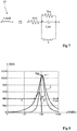
- the figure 3 shows an example of a common Bootstrap setup.
- This figure illustrates the principle of a Bootstrap assembly for supplying control circuits of an arm composed of two MOS transistors Tup and Tbottom in series between two terminals 41 and 43 for applying a DC voltage Vdc.
- the midpoint 45 of the series association constitutes an output terminal intended for a load not shown.
- the respective sources of the transistors Tup and Tbottom are connected to terminals 45 and 43.
- the control of each transistor Tup, Tbottom is ensured by a circuit (DRIVER) 5up, respectively 5bottom, of which an input terminal receives a signal CTRLH, respectively CTRLL and of which an output terminal OUT is connected, by a resistor R5, called gate, to the gate of the transistor Tup, respectively Tbottom.
- DRIVER circuit
- each 5up, 5bottom circuit has a CMOS structure of two switches SW in series (see the 5up circuit), the midpoint of which provides an all-or-nothing signal for controlling the Tup or Tbottom transistor and the gates of which receive representative information. of the associated control signal CTRLH or CTRLL.
- the control signals CTRLH and CTRLL must be generated so as to avoid any simultaneous conduction of the transistors Tup and Tbottom which would have the consequence of putting the voltage source Vdc in short circuit.
- a Bootstrap circuit Insofar as the transistors Tup and Tbottom are N-channel MOS transistors, the signals OUT of the circuits 5up and 5bottom must be respectively referenced to the potential of terminal 45 (for the circuit 5up) and to the potential of terminal 43 (for the 5bottom circuit).
- the principle of a Bootstrap circuit is to supply, without galvanic isolation, a floating potential circuit from a supply referenced to a fixed potential.
- a usual Bootstrap circuit comprises a source 61 of direct voltage referenced to the terminal 43 directly supplying the circuit 5bottom and the positive terminal of which is connected, by a diode 63 in series with a resistor 65, to a positive supply terminal of the 5up circuit.
- This positive supply terminal is also connected, by a capacitor 69, to the output terminal 45.
- the voltage source 61 is generally a low voltage source (of a few volts) compatible with the voltages that the control circuits can withstand. 5up and 5bottom. Such a circuit works because the switches Tup and Tbottom are controlled so as not to be busy at the same time.
- the circuit 5bottom associated with the switch Tbottom, can be controlled directly by the voltage source 61 insofar as it has a common reference to this voltage source.
- the voltage source 61 charges the capacitor 69 positively with respect to the terminal 45 and thus creates an auxiliary supply for the 5up circuit.
- the diode 63 conditioning the direction of flow from the source 61 to the capacitor 69, prevents this capacitor 69 from discharging other than to supply the circuit 5up.
- the diode 63 also makes it possible to block the high voltage (Vdc plus the voltage across the capacitor 69) which is present on its cathode when the Tbottom transistor is open or blocked (OFF), and thus protects the voltage source 61.
- the resistor 65 is used to limit the inrush currents when recharging the capacitor 69.
- Such a Bootstrap assembly is highly dependent on the operating conditions and in particular on the duty cycle and on the frequency of the signals CTRLH and CTRLL. Indeed, the charging of the capacitor 69 is carried out only during the cycles where the transistor Tbottom is closed.
- a Bootstrap montage as illustrated by the figure 3 cannot therefore be transposed to the generation of supply voltages for MOS switch control circuits of a current inverter as illustrated by the figure 2 . More generally, such an arrangement cannot be transposed to the control of MOS switches in series such that they are simultaneously blocked and on. In other words, it does not transpose to the supply of control circuits of two transistors with common sources in series between two potentials including a variable potential (point A, B or C in the example of figure 2 ).
- the figure 4 represents an embodiment of a Bootstrap assembly for generating supply voltages of control circuits of two transistors in series, mounted head to tail.
- terminal 71 is terminal 21 and terminal 73 is one of terminals A (switch 31), B (switch 33) and C (switch 35), or terminal 71 is one terminals A (switch 32), B (switch 34) and C (switch 36) and terminal 73 is terminal 23.
- switches HM and LM typically MOS transistors, preferably with N channel mounted at common sources
- the transistor HM is controlled by a circuit (DRIVER) 5H and the transistor LM is controlled by a circuit (DRIVER) 5L, output terminals OUTH and OUTL of circuits 5H and 5L being connected, preferably by resistors R5, to the gates respective of the HM and LM transistors.
- Each circuit 5H, 5L receives a control signal CTH, respectively CTL. It is noted that, unlike the signals CTRLH and CTRLL of the figure 3 which must be different for the two circuits 5up and 5bottom, the CTH and CTL signals do not require any particular property, the switches being controlled at all times by their source.
- the circuit 5H with a DC voltage source 81 referenced to the source SH of the transistor HM.
- the most positive terminal + of the source 81 is connected, preferably connected, to the positive supply terminal 75 of the circuit 5H and the most negative terminal - of the source 81 is preferably connected connected, to the source SH of the transistor HM thus making it possible to reference its gate control signal at the floating potential of the terminal SH.
- the voltage source 81 is a low voltage source (of a few volts) compatible with the voltage which the control circuit 5H can withstand.
- the circuit 5L is supplied by a capacitor 89, the two electrodes of which are connected, preferably connected, to the supply terminals of the circuit 5L.
- the transfer of energy from the voltage source 81 to the capacitor 89 is carried out, according to the embodiments described, by a circuit Z8 whose impedance varies as a function of the frequency.
- the role of this arrangement is to transfer energy from the voltage source 81 to the capacitor 89 with a particular frequency response so as to block the voltages induced by the inductance Lss.
- the assembly Z8 connects the terminal 75 to the negative electrode of the capacitor 89 (the one connected, preferably connected, to a terminal 77 for applying the most negative potential of the supply voltage of the circuit 5L).
- the Z8 assembly comprises, in series between the terminals 75 and 77, a ferrite bead 87 (ferrite bead), a diode 83 and a resistor 85, the cathode of the diode 83 being directed towards the capacitor 89 to prevent its discharge into the voltage source 81.
- the diode 83 contributes to protecting the voltage source 81 by blocking ( at least partially) the negative voltages induced by the inductance Lss.
- Resistor 85 prevents overvoltages at start-up. Indeed, as will emerge better from the presentation of Figures 7 and 8 , the ferrite bead 87 behaves like an inductor at low frequencies. Without the resistor 85, there is a risk of inducing overvoltages at the terminals of the capacitor 89 which could damage it. Resistor 85 can, if necessary, be provided by the dynamic resistance of diode 83, which avoids a component.
- the choice of a ferrite bead comes from a new analysis of the behavior of the potentials of the respective sources SH and SL of the HM and HL transistors during switching operations, in particular during switching operations to turn the HM and HL transistors on.
- the parasitic inductance Lss behaves like a current source and introduces a potential difference between the sources SH and SL. This phenomenon is particularly present in the applications targeted by the present description where the switching speed is high, for example of the order of 2 to 10 A / ns due to the equivalent frequency at which the HM and HL transistors see the variations. of current (of the order of a hundred MHz).
- Zener diodes can be connected to the terminals of the capacitor 89 in order to protect it against possible overvoltages.
- the threshold of the Zener diode (s) is then chosen as a function of the supply voltage desired for the 5L circuit.
- the figure 5 represents, schematically and partially, a model of the assembly of the figure 4 .
- the figure 6 shows, schematically and partially, another model of the assembly of the figure.
- FIGs 5 and 6 schematically represent the respectively intermediate models ( figure 5 ) and in small signals ( figure 6 ) mounting the figure 4 without the inductor Z8.
- Each transistor HM, LM can be likened to a gate-source capacitance CGSH, respectively CGHL, between the resistance RGH, respectively RGL, and the parasitic inductance Lss connecting the sources together.
- the capacitors 81 and 89 are respectively connected to the terminals of the inductor Lss by inductors LSH and LSV. During switching operations, this parasitic inductance Lss can be considered to be in parallel with a dynamic current source I linked to the switching of the current of the inductance.
- the scheme of the figure 5 can be simplified, in small signals, into a model ( figure 6 ) in which the source electrodes of the capacities CGSH and CGSL are connected by the inductance Lss and the current source I in parallel, and in which each source electrode is connected to the gate electrode of the capacity CGSH, respectively GGSL , concerned by the serial association of the inductor LSH, respectively LSL, of inductance LGH, respectively LGL, and of resistance RGH, respectively RGL.
- the figure 7 shows the equivalent electrical diagram of a ferrite bead.
- a ferrite bead can be symbolized by an Lbead inductor.
- This inductance Lbead is in fact equivalent to a resistance Rdc in series with a parallel association of an inductance L, of a capacitance Cpar and of a resistance Rac, the contributions of which are different according to the frequency.
- the behavior of the ferrite bead is different as a function of the frequency with respect to the resonant frequency conditioned by the inductance L and the capacitance Cpar.
- a ferrite bead is an element providing a filtering function, which differentiates it from an inductive storage element.
- a ferrite bead is usually used to reduce (filter) parasites electromagnetic high frequencies (higher than ten, even a hundred MHz) on cables.
- the figure 8 illustrates the frequency response of an example of a ferrite bead.
- the figure 8 shows an example of the shape of the impedance (in ohms) provided by the ferrite bead 87 as a function of the frequency f (in MHz).
- Three curves R, X and Z are present in figure 8 , the curves X and R respectively representing the real and imaginary parts of the impedance illustrated by the curve Z.
- the figure 9 illustrates the susceptibility of the control voltage of a transistor of the circuit of the figure 4 .
- the figure 9 represents, for example, the evolution of the electrical susceptibility of the gate-source voltage of a transistor of a circuit produced according to the figure 4 and a circuit in which the terminals 75 and 77 are directly connected, as a function of the frequency of disturbances provided by the parasitic inductance Lss for connecting the sources SH and SL.
- the susceptibility S and the frequency f are on logarithmic scales.
- Two curves 91 and 93 illustrate the susceptibility of the circuit of the figure 4 for a parasitic inductance Lss respectively of the order of 15 nH (curve 91) and of the order of 30 nH (curve 93).
- curves 95 and 97 illustrate the frequency susceptibility of the circuit with a direct connection between terminals 75 and 77 and a parasitic inductance Lss respectively of the order of 15 nH (curve 95) and of the order of 30 nH (curve 97 ).
- the ferrite bead is placed, relative to the gates of the transistors, upstream of the gate control circuits 5H and 5L.
- ferrite bead The choice of ferrite bead depends on the application and the characteristics of the assembly.
- the determination can be made empirically by testing different ferrite beads. Preferably, however, certain characteristics of the assembly are evaluated in order to facilitate the choice of the ferrite bead.
- an estimate of the switching edges (dI / dt) provides an approximation of the desired resonance for the ferrite.
- This dI / dt can be deduced from characteristic data of the transistors and of the control circuits such as the rise times and fall times.
- the available range of resonant frequency values for the ferrite beads (which extends from about 10 MHz to about 1 GHz) offers enough choice depending on the constraints of the circuit.
- an advantage induced by the assembly described is that it makes it possible to damp the drain-source current oscillations during switches. This reduces the oscillations at the gate-source and drain-source voltages of the transistors. This contributes to improving the response to electromagnetic disturbances and avoids the use of dedicated circuits.
- the figure 10 shows another embodiment of a power supply circuit for controlling circuits of two transistors in series, applied to a power supply with double polarity (positive and negative).
- the circuit 5H is supplied by a voltage supplied by two voltage sources 81 and 81 'in series between terminals 75 and 115 supplying the circuit 5H.
- the midpoint of this series association is connected, preferably connected, to the source SH of the transistor HM.
- On the LM transistor side its source is connected, preferably connected to the midpoint of a series association of two capacitors 89 and 89 'between terminals 117 and 77 supplying the circuit 5L.
- the midpoint of this series association is connected, preferably connected, to the source SL of the transistor LM.
- Each capacitor 89, 89 ′ is in parallel with a Zener diode 109, respectively 109 ′, fixing the voltage across its terminals, in the event of overvoltages.
- a first Bootstrap assembly consisting of a diode 83, a resistor 85 and a ferrite bead 87 (symbolized here by an inductive element), connects the terminals 75 and 77 as in figure 4 , the anode of diode 83 being on terminal side 75.
- a second Bootstrap assembly consisting of a diode 103, a resistor 105 and a ferrite bead 107, connects terminals 115 and 117, the anode of diode 103 being on terminal side 117.
- the embodiments described transpose to any supply arrangement, by a single voltage source, of two transistor gate control circuits in series between two terminals of which at least one is at floating potential.
Landscapes
- Engineering & Computer Science (AREA)
- Power Engineering (AREA)
- Physics & Mathematics (AREA)
- Electromagnetism (AREA)
- Inverter Devices (AREA)
- Dc-Dc Converters (AREA)
- Power Conversion In General (AREA)
Applications Claiming Priority (1)
| Application Number | Priority Date | Filing Date | Title |
|---|---|---|---|
| FR1871635A FR3088779B1 (fr) | 2018-11-20 | 2018-11-20 | Circuit d’alimentation de circuits de commande d’interrupteurs |
Publications (1)
| Publication Number | Publication Date |
|---|---|
| EP3657677A1 true EP3657677A1 (de) | 2020-05-27 |
Family
ID=66530114
Family Applications (1)
| Application Number | Title | Priority Date | Filing Date |
|---|---|---|---|
| EP19209871.3A Pending EP3657677A1 (de) | 2018-11-20 | 2019-11-18 | Stromversorgungsschaltkreis für steuerschaltungen von schaltern |
Country Status (3)
| Country | Link |
|---|---|
| US (1) | US11632040B2 (de) |
| EP (1) | EP3657677A1 (de) |
| FR (1) | FR3088779B1 (de) |
Families Citing this family (2)
| Publication number | Priority date | Publication date | Assignee | Title |
|---|---|---|---|---|
| US11695331B2 (en) * | 2019-08-05 | 2023-07-04 | Hitachi Energy Switzerland Ag | Converter arrangement |
| US11522439B2 (en) * | 2020-01-16 | 2022-12-06 | Mediatek Inc. | Switching regulator with driver power clamp |
Citations (2)
| Publication number | Priority date | Publication date | Assignee | Title |
|---|---|---|---|---|
| GB2324664A (en) | 1997-04-23 | 1998-10-28 | Int Rectifier Corp | Protection of half-bridge driver IC against negative voltage failures |
| WO2001052396A2 (de) | 2000-01-14 | 2001-07-19 | Infineon Technologies Ag | Schaltungsanordnung zum anlegen einer versorgungsspannung an eine last |
Family Cites Families (7)
| Publication number | Priority date | Publication date | Assignee | Title |
|---|---|---|---|---|
| DE4225410C1 (de) * | 1992-07-31 | 1994-01-05 | Siemens Nixdorf Inf Syst | Schaltungsanordnung zum Ansteuern eines in einem Abwärtswandler angeordneten Schaltelements |
| US6304137B1 (en) * | 1999-12-23 | 2001-10-16 | Red Chip Company Limited | Output stage for high power class D amplifiers |
| US6707257B2 (en) * | 2002-08-08 | 2004-03-16 | Datex-Ohmeda, Inc. | Ferrite stabilized LED drive |
| JP4998550B2 (ja) * | 2007-03-02 | 2012-08-15 | 株式会社村田製作所 | 周波数可変帯域除去フィルタ |
| JP5656072B2 (ja) * | 2011-01-25 | 2015-01-21 | サンケン電気株式会社 | Dc−dcコンバータ |
| CN204442157U (zh) * | 2014-12-26 | 2015-07-01 | 上海奇电电气科技有限公司 | 一种变频器专用自举驱动电路 |
| JP6561745B2 (ja) * | 2015-10-02 | 2019-08-21 | 株式会社村田製作所 | インダクタ部品、パッケージ部品およびスィッチングレギュレータ |
-
2018
- 2018-11-20 FR FR1871635A patent/FR3088779B1/fr active Active
-
2019
- 2019-11-18 EP EP19209871.3A patent/EP3657677A1/de active Pending
- 2019-11-19 US US16/688,862 patent/US11632040B2/en active Active
Patent Citations (2)
| Publication number | Priority date | Publication date | Assignee | Title |
|---|---|---|---|---|
| GB2324664A (en) | 1997-04-23 | 1998-10-28 | Int Rectifier Corp | Protection of half-bridge driver IC against negative voltage failures |
| WO2001052396A2 (de) | 2000-01-14 | 2001-07-19 | Infineon Technologies Ag | Schaltungsanordnung zum anlegen einer versorgungsspannung an eine last |
Also Published As
| Publication number | Publication date |
|---|---|
| FR3088779B1 (fr) | 2020-12-04 |
| US11632040B2 (en) | 2023-04-18 |
| FR3088779A1 (fr) | 2020-05-22 |
| US20200161963A1 (en) | 2020-05-21 |
Similar Documents
| Publication | Publication Date | Title |
|---|---|---|
| EP2355331A1 (de) | Wandlervorrichtung und mit einer solchen Vorrichtung ausgerüstete unterbrechungslose Versorgung | |
| EP3096456B1 (de) | Bidirektionaler leistungsumschalter mit verbesserten umschaltleistungen | |
| FR3002703A1 (fr) | Dispositif de commande employe dans un systeme d'alimentation electrique a decoupage | |
| EP3657677A1 (de) | Stromversorgungsschaltkreis für steuerschaltungen von schaltern | |
| FR2942088A1 (fr) | Onduleur de tension a 3n-4 niveaux | |
| EP1005161B1 (de) | Steuerungsschaltung für einen Halbleiterschalter im Wechselbetrieb | |
| FR3059490A1 (fr) | Dispositif de commutation d'un circuit de puissance presentant un circuit passif de protection | |
| EP2751916A1 (de) | Leistungsstarker wandler mit parallel geschalteten niedrigenergietransistoren | |
| FR3072520A1 (fr) | Circuit de commande d'un thyristor ou triac | |
| EP3726731B1 (de) | Steuerschaltkreis von transistoren | |
| EP3840200B1 (de) | Schaltersteuerungssperre | |
| FR2823383A1 (fr) | Onduleur pour l'alimentation de lampe a decharge | |
| EP2781023B1 (de) | Leistungsvariator | |
| WO2012084389A2 (fr) | Convertisseur de puissance équipé en sortie d'un dispositif de filtrage | |
| FR3058850A1 (fr) | Commutateur de puissance comportant une pluralite de transistors a effet de champ montes en parallele | |
| WO2022117481A1 (fr) | Convertisseur de puissance | |
| FR3059497A1 (fr) | Procede et circuit de commande d'un dispositif de commutation d'un circuit de puissance | |
| EP1070391B1 (de) | Verfahren und vorrichtung zum steuern eines leistungs-schalttransistors mit isoliertem gate | |
| EP3857705A1 (de) | Elektromagnetische filtrierung einer steuerschaltung eines elektromotors | |
| FR3054088A1 (fr) | Commutateur ultra-rapide a haute tension. | |
| EP3804137A1 (de) | Schaltersystem mit spannungsbegrenzungsschaltung, schaltarm und elektrischem wandler | |
| FR3080237A1 (fr) | Onduleur a source impedante comprenant deux reseaux de quasi z-source | |
| EP3836398A1 (de) | Vorrichtung zur steuerung eines schalters | |
| WO2022162296A1 (fr) | Circuit de commande de transistors de puissance d'un bras d'onduleur | |
| EP3657678A1 (de) | Steuerschaltkreis von leistungstransistoren |
Legal Events
| Date | Code | Title | Description |
|---|---|---|---|
| PUAI | Public reference made under article 153(3) epc to a published international application that has entered the european phase |
Free format text: ORIGINAL CODE: 0009012 |
|
| STAA | Information on the status of an ep patent application or granted ep patent |
Free format text: STATUS: REQUEST FOR EXAMINATION WAS MADE |
|
| 17P | Request for examination filed |
Effective date: 20191118 |
|
| AK | Designated contracting states |
Kind code of ref document: A1 Designated state(s): AL AT BE BG CH CY CZ DE DK EE ES FI FR GB GR HR HU IE IS IT LI LT LU LV MC MK MT NL NO PL PT RO RS SE SI SK SM TR |
|
| AX | Request for extension of the european patent |
Extension state: BA ME |
|
| STAA | Information on the status of an ep patent application or granted ep patent |
Free format text: STATUS: EXAMINATION IS IN PROGRESS |
|
| 17Q | First examination report despatched |
Effective date: 20220517 |