EP3657474B1 - Aerial vehicle terrain awareness display - Google Patents
Aerial vehicle terrain awareness display Download PDFInfo
- Publication number
- EP3657474B1 EP3657474B1 EP20152891.6A EP20152891A EP3657474B1 EP 3657474 B1 EP3657474 B1 EP 3657474B1 EP 20152891 A EP20152891 A EP 20152891A EP 3657474 B1 EP3657474 B1 EP 3657474B1
- Authority
- EP
- European Patent Office
- Prior art keywords
- aerial vehicle
- map
- unmanned aerial
- radio frequency
- display
- Prior art date
- Legal status (The legal status is an assumption and is not a legal conclusion. Google has not performed a legal analysis and makes no representation as to the accuracy of the status listed.)
- Active
Links
Images


Classifications
-
- G—PHYSICS
- G08—SIGNALLING
- G08G—TRAFFIC CONTROL SYSTEMS
- G08G5/00—Traffic control systems for aircraft
- G08G5/70—Arrangements for monitoring traffic-related situations or conditions
- G08G5/74—Arrangements for monitoring traffic-related situations or conditions for monitoring terrain
-
- G—PHYSICS
- G08—SIGNALLING
- G08G—TRAFFIC CONTROL SYSTEMS
- G08G5/00—Traffic control systems for aircraft
- G08G5/20—Arrangements for acquiring, generating, sharing or displaying traffic information
- G08G5/22—Arrangements for acquiring, generating, sharing or displaying traffic information located on the ground
-
- G—PHYSICS
- G08—SIGNALLING
- G08G—TRAFFIC CONTROL SYSTEMS
- G08G5/00—Traffic control systems for aircraft
- G08G5/50—Navigation or guidance aids
- G08G5/55—Navigation or guidance aids for a single aircraft
-
- G—PHYSICS
- G08—SIGNALLING
- G08G—TRAFFIC CONTROL SYSTEMS
- G08G5/00—Traffic control systems for aircraft
- G08G5/50—Navigation or guidance aids
- G08G5/57—Navigation or guidance aids for unmanned aircraft
-
- B—PERFORMING OPERATIONS; TRANSPORTING
- B64—AIRCRAFT; AVIATION; COSMONAUTICS
- B64U—UNMANNED AERIAL VEHICLES [UAV]; EQUIPMENT THEREFOR
- B64U2201/00—UAVs characterised by their flight controls
- B64U2201/20—Remote controls
Definitions
- the present application is generally related to displaying terrain along projected flight paths of aerial vehicles.
- UAVs unmanned aerial vehicles
- UAVs are used for many applications by entities such as the military, law enforcement, and the like, and by individuals, such as UAV enthusiasts.
- pilots of manned aircraft UAVs are unmanned and the controllers of the UAVs are not located inside of the aircraft that is being controlled.
- Controller inputs can be transmitted to UAVs in flight to control the flight path of the UAV via ground based systems.
- the flight path of the UAV may be tracked via the ground based systems, and the UAV may transmit data back to the controller.
- a controller on the ground may not have the same situational awareness about the UAV and its surroundings as a pilot situated in an aircraft. Controllers of UAVs may benefit from information presented in a way that gives them greater awareness of the UAV and its surroundings.
- Cited document WO 2009/129937 A1 discloses an unmanned aerial system (UAS) position reporting system includes an air traffic control reporting system (ATC-RS) coupled with a ground control station (GCS) of an UAS where the ATC-RS includes an automatic dependent surveillance broadcast (ADS-B) and a traffic information services broadcast (TIS-B) transceiver and one or more telecommunications modems.
- the ATC-RS may receive position data of the UAS in an airspace from the GCS and communicates the position of the UAS to a civilian air traffic control center (ATC) or to a military command and control (C2) communication center.
- RFLOS radio frequency line of sight
- Cited document US 2010/084513 A1 discloses a method of remotely controlling an aerial vehicle within an environment, including providing a control station in communication with the aerial vehicle, providing a map of the environment, receiving target world coordinates for the aerial vehicle within the environment, determining a desired velocity vector to direct the aerial vehicle to the target world coordinates at a speed proportional to the distance between the aerial vehicle and the target world coordinates, and directing the aerial vehicle along the desired velocity vector until the aerial vehicle reaches the target world coordinates.
- Illustrative examples of the present disclosure include, without limitation, methods, structures, and systems.
- the present disclosure relates to a method of displaying information about an unmanned aerial vehicle as defined in independent claim 1. Further examples of this method form the subject matter of dependent claims 2-5.
- the disclosure relates to a system configured to display information pertaining to an unmanned aerial vehicle as defined in independent claim 6. Further examples of this system form the subject matter of dependent claims 7-10.
- the present disclosure relates to a non-transitory computer-readable storage medium having stored thereon computer-readable instructions as defined in independent claim 11.
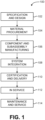
- Non-claimed examples in this disclosure may be described in the context of aircraft manufacturing and service method 100 as shown in Figure 1 and an aircraft 200 as shown in Figure 2 .
- aircraft manufacturing and service method 100 may include specification and design 102 of aircraft 200 and material procurement 104.
- aircraft 200 During production, component and subassembly manufacturing 106 and system integration 108 of aircraft 200 takes place. Thereafter, aircraft 200 may go through certification and delivery 110 in order to be placed in service 112. While in service by a customer, aircraft 200 is scheduled for routine maintenance and service 114 (which may also include modification, reconfiguration, refurbishment, and so on).
- Each of the processes of aircraft manufacturing and service method 100 may be performed or carried out by a system integrator, a third party, and/or an operator (e.g., a customer).
- a system integrator may include, without limitation, any number of aircraft manufacturers and major-system subcontractors
- a third party may include, for example, without limitation, any number of venders, subcontractors, and suppliers
- an operator may be an airline, leasing company, military entity, service organization, and so on.
- aircraft 200 produced by aircraft manufacturing and service method 100 may include airframe 202 with a plurality of systems 204 and interior 206.
- systems 204 include one or more of propulsion system 208, electrical system 210, hydraulic system 212, and environmental system 214. Any number of other systems may be included in this example.
- propulsion system 208 electrical system 210
- hydraulic system 212 hydraulic system 212
- environmental system 214 any number of other systems may be included in this example.
- Any number of other systems may be included in this example.
- an aerospace example is shown, the principles of the disclosure may be applied to other industries, such as the automotive industry.
- Apparatus and methods embodied herein may be employed during any one or more of the stages of aircraft manufacturing and service method 100.
- components or subassemblies corresponding to component and subassembly manufacturing 106 may be fabricated or manufactured in a manner similar to components or subassemblies produced while aircraft 200 is in service.
- Figure 3 illustrates non-claimed systems or operating environments, denoted generally at 300, that provide flight plans for UAVs while routing around obstacles having spatial and temporal dimensions.
- These systems 300 may include one or more flight planning systems 302.
- Figure 3 illustrates several examples of platforms that may host the flight planning system 302. These examples may include one or more server-based systems 304, one or more portable computing systems 306 (whether characterized as a laptop, notebook, tablet, or other type of mobile computing system), and/or one or more desktop computing systems 308.
- the flight planning system 302 may be a ground-based system that performs pre-flight planning and route analysis for the UAVs, or may be a vehicle-based system that is housed within the UAVs themselves.
- Implementations of this description may include other types of platforms as well, with Figure 3 providing non-limiting examples.
- the description herein contemplates other platforms for implementing the flight planning systems, including but not limited to wireless personal digital assistants, smartphones, or the like.
- the graphical elements used in Figure 3 to depict various components are chosen only to facilitate illustration, and not to limit possible implementations of the description herein.
- the flight planning system 302 may include one or more processors 310, which may have a particular type or architecture, chosen as appropriate for particular implementations.
- the processors 310 may couple to one or more bus systems 312 that are chosen for compatibility with the processors 310.
- the flight planning systems 302 may include one or more instances of computer-readable storage media 314, which couple to the bus systems 312.
- the bus systems may enable the processors 310 to read code and/or data to/from the computer-readable storage media 314.
- the media 314 may represent storage elements implemented using any suitable technology, including but not limited to semiconductors, magnetic materials, optics, or the like.
- the media 314 may include memory components, whether classified as RAM, ROM, flash, or other types, and may also represent hard disk drives.
- the storage media 314 may include one or more modules 316 of instructions that, when loaded into the processor 310 and executed, cause the server 302 to provide flight plan computation services for a variety of UAVs 318. These modules may implement the various algorithms and models described and illustrated herein.
- the UAVs 318 may be of any convenient size and/or type as appropriate for different applications. In different scenarios, the UAVs may range from relatively small drones to relatively large transport aircraft. Accordingly, the graphical illustration of the UAV 318 as shown in FIG. 1 is representative only, and is not drawn to scale.
- the flight plan services 316 may generate respective flight plan solutions 320 for the UAVs 318 based on inputs 322, with flight planning personnel 324 and/or one or more databases 326 providing inputs 322.
- the flight planning system 302 may load the solutions into the UAVs 318, as represented by the arrow connecting blocks 302 and 318 in Figure 3 .
- the flight planning system 302 may also provide the solutions 320 to the flight planner 324 and/or the databases 326, as denoted by the arrow 320A.
- a controller of a UAV is located remotely from the UAV and may not have the same situational awareness that a pilot may have when located inside of an aircraft during flight.
- the controller of a UAV may not have the ability to appreciate terrain surrounding the UAV. If the controller of the UAV cannot see the geographic area surrounding the UAV, the controller may inadvertently command the UAV to enter a dangerous area and/or crash into terrain.
- a layer may be overlaid on the controller's display showing one or more areas indicative of an unsafe elevation.
- a layer may be referred to herein as "terrain awareness layer.”
- an unsafe elevation may be depicted using colored areas on the current display showing where the UAV, given the current altitude of the UAV, is within a predefined level above the terrain.
- the display may provide a first overlay showing all areas where the UAV will be less than 100 feet above terrain at the UAV's current altitude.
- the display may also indicate a second overlay showing all areas where the UAV will be less than a second altitude above terrain at the UAV's current altitude (for example, 200 feet above terrain).
- a second altitude above terrain at the UAV's current altitude for example, 200 feet above terrain.
- the terrain awareness layer may be automatically rendered on the UAV controller's display if it is determined that, within some predetermined time period, the UAV will enter an "unsafe" area (i.e., an area where the UAV will be less than a predefined altitude above terrain at the UAV's current altitude).
- the predefined altitude may be automatically set. In other examples, the predefined altitude may be manually set by the operator. In some examples, if it is determined that the UAV will enter an unsafe area, the terrain awareness layer may be configured so that the layer cannot be removed by the operator.
- the operator may request display of the terrain awareness layer, even if the UAV is not headed toward an unsafe area. In this way, the operator may maintain awareness of the potential unsafe areas even if an unsafe area is not part of the current flight path.
- the terrain awareness layer may be displayed when the operator is engaging the controls to change the current altitude of the UAV.
- the user controls may include a graphical "sliding" altitude control.
- the terrain awareness layer may automatically change based on the currently selected altitude. In this way the controller can instantly view the unsafe altitudes as the controller considers various UAV altitudes.
- the terrain awareness layer may be depicted using various colors or textures to indicate the areas corresponding to different unsafe altitudes. For example, areas that will have 100 feet or less clearance above ground at the current UAV altitude may be indicated in red, and areas that will have 200 feet or less clearance above ground at the current UAV altitude may be indicated in yellow.
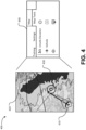
- Figure 4 depicts an example of a display 400 that does not form part of the claimed invention, but that can assist a UAV controller to view the terrain for the UAV flight and real-time information about the terrain with respect ot the altitude of the UAV.
- the display 400 depicted in Figure 4 may also include real-time information about the flight.
- the display 400 includes an indication of the aircraft position 410 during the flight.
- a first region 420 may indicate one or more areas where the distance between the current altitude of the aircraft 410 is less than a first predefined threshold.
- a second region 430 may indicate one or more areas where the distance between the current altitude of the aircraft 410 is less than a second predefined threshold.
- a set of user interface controls and indications 440 may be provided for requesting adding the first and second regions 420 and 430 to the current display 400.
- Data to develop the terrain awareness layer can be stored locally on a system that is associated with the display 400, such as on a computing device that includes the display 400.
- the data to develop the terrain awareness layer can also be obtained from a remote system, such as the NASA Shuttle Radar Topography Mission (SRTM), the USGS Global Multi-resolution Terrain Elevation Data (GMTED), and the like.
- SRTM NASA Shuttle Radar Topography Mission
- GMTED USGS Global Multi-resolution Terrain Elevation Data
- the display 400 can display a warning that terrain data is not available. In this way, if the display 400 can indicate to the operator that the data is not available rather than a false indication that altitudes are safe.
- the display 400 can be part of a user interface that allows a controller to interact with the display 400.
- a user interface may be used to adjust the display and/or the programming of the UAV. For example, movement of some controls associated with the display 400 can effect a change in the actual altitude of the UAV as it is flying.
- an RF link analysis layer is provided that indicates a real-time analysis of RF links in the current UAV flight scenario.
- Such an RF link analysis layer is useful to provide the operator of the UAV with information to make real-time mission planning and execution decisions, without the need to use rule-of-thumb estimates of link performance.
- UAVs typically operate with one or more ground antennae that may be directional or omnidirectional and communicatively linked to downlink graphics data to the ground antennae as well as downlink/uplink telemetry and command data. It is therefore useful for the operator to avoid not only terrain hazards, but also loss of RF contact with the UAV.
- a UAV operator may be provided real-time RF coverage of paired RF transmitters and receivers.
- the information provided in the RF link analysis layer may include information such as antenna pattern, gain, type, and power capabilities.
- the RF link analysis layer provides the operator the ability to visually determine how strong an RF signal is for a particular area given a UAV's position.
- RF link analysis layer may include information determined by comparing the predicted signal strength of RF links of a given area to the signal strength corresponding to lost communication and determining if that area will result in lost communication.
- the user may request an RF link analysis layer in areas outside of the planned flight path (or without the UAV) so that the operator can determine the effects of changing the current flight path with regard to RF link strength and propagation patterns.
- colored areas are indicated on the user display overlaid on a current flight map indicating RF link analysis data.
- the data may include signal strength and/or error rate.
- the data can be updated at a predetermined update rate.
- the data is also updated based on the flight path of the UAV. For example, the UAV may sufficiently change position where the RF link analysis is changed and the RF link analysis layer may be redrawn.
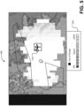
- Figure 5 depicts an embodiment of a display 500 in accordance with the invention that provides RF link analysis information in real time to a UAV controller.
- the display 500 depicted in Figure 5 also includes real-time information about the flight.
- the display 500 includes an indication of the aircraft position 510 during the flight.
- fixed size portions 520 of the display are color coded to indicate a relative estimated strength of the signal within the fixed size portion 520.
- the fixed size portion 520 is a tile representing a predetermined area represented on the map.
- a set of user indications 530 is provided for identifying the signal strengths depicted in the current display 500.
- Figure 6 depicts an example of a method 600 of displaying information pertaining to an air vehicle which does not form part of the claimed invention.
- information is displayed that is indicative of first portions of a map where a distance between a current altitude of the air vehicle and terrain in the map are within a first threshold.
- information is displayed indicative of second portions of a map where a distance between the current altitude of the air vehicle and terrain in the map are within a second threshold.
- the first and second portions are updated based on a change in the current altitude of the air vehicle.
- Figure 7 depicts an embodiment of a method 700 of displaying information pertaining to an air vehicle which, albeit not falling under the scope of the claims, is useful to understand the invention.
- a map including a projected flight path of an aircraft is displayed.
- location-based information pertaining to radio frequency (RF) status between the aircraft and at least one ground radio is displayed on the map.
- the location-based information pertaining to RF status is updated based on a change in the current position of the air vehicle.
- RF radio frequency
- FIG. 8 and the following discussion are intended to provide a brief general description of a suitable computing environment in which the methods and systems disclosed herein and/or portions thereof may be implemented.
- the functions of server 304, laptop 306, desktop 308, flight planning system 302, and database 326 may be performed by one or more devices that include some or all of the aspects described in regard to FIG. 8 .
- Some or all of the devices described in FIG. 8 that may be used to perform functions of the claimed examples may be configured in other devices and systems such as those described herein.
- some or all of the devices described in FIG. 8 may be included in any device, combination of devices, or any system that performs any aspect of a disclosed example.
- program modules include routines, programs, objects, components, data structures and the like that perform particular tasks or implement particular abstract data types.
- program modules include routines, programs, objects, components, data structures and the like that perform particular tasks or implement particular abstract data types.
- the methods and systems disclosed herein and/or portions thereof may be practiced with other computer system configurations, including hand-held devices, multi-processor systems, microprocessor-based or programmable consumer electronics, network PCs, minicomputers, mainframe computers and the like.
- the methods and systems disclosed herein may also be practiced in distributed computing environments where tasks are performed by remote processing devices that are linked through a communications network.
- program modules may be located in both local and remote memory storage devices.
- FIG. 8 is a block diagram representing a general purpose computer system in which aspects of the methods and systems disclosed herein and/or portions thereof may be incorporated.
- the example general purpose computing system includes computer 820 or the like, including processing unit 821, system memory 822, and system bus 823 that couples various system components including the system memory to processing unit 821.
- System bus 823 may be any of several types of bus structures including a memory bus or memory controller, a peripheral bus, and a local bus using any of a variety of bus architectures.
- the system memory may include read-only memory (ROM) 824 and random access memory (RAM) 825.
- BIOS Basic input/output system 826
- BIOS Basic input/output system 826
- Computer 820 may further include hard disk drive 827 for reading from and writing to a hard disk (not shown), magnetic disk drive 828 for reading from or writing to removable magnetic disk 829, and/or optical disk drive 830 for reading from or writing to removable optical disk 831 such as a CD-ROM or other optical media.
- Hard disk drive 827, magnetic disk drive 828, and optical disk drive 830 may be connected to system bus 823 by hard disk drive interface 832, magnetic disk drive interface 833, and optical drive interface 834, respectively.
- the drives and their associated computer-readable media provide non-volatile storage of computer-readable instructions, data structures, program modules and other data for computer 820.
- a number of program modules may be stored on hard disk drive 827, magnetic disk 829, optical disk 831, ROM 824, and/or RAM 825, including an operating system 835, one or more application programs 836, other program modules 837 and program data 838.
- a user may enter commands and information into the computer 820 through input devices such as a keyboard 840 and pointing device 842.
- Other input devices may include a microphone, joystick, game pad, satellite disk, scanner, or the like.
- serial port interface 846 that is coupled to the system bus, but may be connected by other interfaces, such as a parallel port, game port, or universal serial bus (USB).
- a monitor 847 or other type of display device may also be connected to the system bus 823 via an interface, such as a video adapter 448.
- a computer may include other peripheral output devices (not shown), such as speakers and printers.
- the example system of FIG. 8 may also include host adapter 855, Small Computer System Interface (SCSI) bus 856, and external storage device 862 that may be connected to the SCSI bus 856.
- SCSI Small Computer System Interface
- the computer 820 may operate in a networked environment using logical and/or physical connections to one or more remote computers or devices, such as remote computer 849, that may represent any of server 304, laptop 306, desktop 308, flight planning system 302, and database 326.
- Each of server 304, laptop 306, desktop 308, flight planning system 302, and database 326 may be any device as described herein capable of performing the determination and display of zero fuel time data and return to base time data.
- Remote computer 849 may be a personal computer, a server, a router, a network PC, a peer device or other common network node, and may include many or all of the elements described above relative to the computer 820, although only a memory storage device 850 has been illustrated in FIG. 8 .
- the logical connections depicted in FIG. 8 may include local area network (LAN) 851 and wide area network (WAN) 852.
- LAN local area network
- WAN wide area network
- computer 820 When used in a LAN networking environment, computer 820 may be connected to LAN 851 through network interface or adapter 853. When used in a WAN networking environment, computer 820 may include modem 854 or other means for establishing communications over wide area network 852, such as the Internet. Modem 854, which may be internal or external, may be connected to system bus 823 via serial port interface 846. In a networked environment, program modules depicted relative to computer 820, or portions thereof, may be stored in a remote memory storage device. It will be appreciated that the network connections shown are example and other means of establishing a communications link between computers may be used.
- Computer 820 may include a variety of computer-readable storage media.
- Computer-readable storage media can be any available tangible, non-transitory, or non-propagating media that can be accessed by computer 820 and includes both volatile and nonvolatile media, removable and non-removable media.
- Computer-readable media may comprise computer storage media and communication media.
- Computer storage media include volatile and nonvolatile, removable and non-removable media implemented in any method or technology for storage of information such as computer-readable instructions, data structures, program modules or other data.
- Computer storage media include, but are not limited to, RAM, ROM, EEPROM, flash memory or other memory technology, CD-ROM, digital versatile disks (DVD) or other optical disk storage, magnetic cassettes, magnetic tape, magnetic disk storage or other magnetic storage devices, or any other tangible medium that can be used to store the desired information and that can be accessed by computer 820. Combinations of any of the above should also be included within the scope of computer-readable media that may be used to store source code for implementing the methods and systems described herein.
Landscapes
- Engineering & Computer Science (AREA)
- Aviation & Aerospace Engineering (AREA)
- Physics & Mathematics (AREA)
- General Physics & Mathematics (AREA)
- Traffic Control Systems (AREA)
- Navigation (AREA)
- User Interface Of Digital Computer (AREA)
- Radar, Positioning & Navigation (AREA)
- Remote Sensing (AREA)
- Instructional Devices (AREA)
Applications Claiming Priority (4)
| Application Number | Priority Date | Filing Date | Title |
|---|---|---|---|
| US201361872215P | 2013-08-30 | 2013-08-30 | |
| US14/453,492 US9685091B2 (en) | 2013-08-30 | 2014-08-06 | Aerial vehicle awareness display |
| EP14759433.7A EP3039665B1 (en) | 2013-08-30 | 2014-08-25 | Aerial vehicle terrain awareness display |
| PCT/US2014/052571 WO2015031281A1 (en) | 2013-08-30 | 2014-08-25 | Aerial vehicle terrain awareness display |
Related Parent Applications (1)
| Application Number | Title | Priority Date | Filing Date |
|---|---|---|---|
| EP14759433.7A Division EP3039665B1 (en) | 2013-08-30 | 2014-08-25 | Aerial vehicle terrain awareness display |
Publications (2)
| Publication Number | Publication Date |
|---|---|
| EP3657474A1 EP3657474A1 (en) | 2020-05-27 |
| EP3657474B1 true EP3657474B1 (en) | 2024-10-02 |
Family
ID=51492494
Family Applications (2)
| Application Number | Title | Priority Date | Filing Date |
|---|---|---|---|
| EP14759433.7A Active EP3039665B1 (en) | 2013-08-30 | 2014-08-25 | Aerial vehicle terrain awareness display |
| EP20152891.6A Active EP3657474B1 (en) | 2013-08-30 | 2014-08-25 | Aerial vehicle terrain awareness display |
Family Applications Before (1)
| Application Number | Title | Priority Date | Filing Date |
|---|---|---|---|
| EP14759433.7A Active EP3039665B1 (en) | 2013-08-30 | 2014-08-25 | Aerial vehicle terrain awareness display |
Country Status (6)
| Country | Link |
|---|---|
| US (1) | US9685091B2 (enExample) |
| EP (2) | EP3039665B1 (enExample) |
| JP (2) | JP6421188B2 (enExample) |
| AU (2) | AU2014311470B2 (enExample) |
| CA (1) | CA2918836C (enExample) |
| WO (1) | WO2015031281A1 (enExample) |
Families Citing this family (20)
| Publication number | Priority date | Publication date | Assignee | Title |
|---|---|---|---|---|
| US10583920B2 (en) | 2013-04-02 | 2020-03-10 | Hood Technology Corporation | Multicopter-assisted system and method for launching and retrieving a fixed-wing aircraft |
| US10569868B2 (en) | 2013-04-02 | 2020-02-25 | Hood Technology Corporation | Multicopter-assisted system and method for launching and retrieving a fixed-wing aircraft |
| FR3024250B1 (fr) * | 2014-07-23 | 2016-12-09 | Airbus Operations Sas | Procede et dispositif d'engagement automatique d'une descente d'urgence automatisee d'un aeronef. |
| AU2016313150A1 (en) * | 2015-08-27 | 2018-03-08 | Dronsystems Limited | A highly automated system of air traffic control (ATM) for at least one Unmanned Aerial Vehicle (Unmanned Aerial Vehicles UAV) |
| US10706821B2 (en) | 2016-02-18 | 2020-07-07 | Northrop Grumman Systems Corporation | Mission monitoring system |
| US10752357B2 (en) | 2016-03-22 | 2020-08-25 | Hood Technology Corporation | Rotorcraft-assisted system and method for launching and retrieving a fixed-wing aircraft into and from free flight |
| US10696420B2 (en) | 2016-08-17 | 2020-06-30 | Hood Technology Corporation | Rotorcraft-assisted system and method for launching and retrieving a fixed-wing aircraft into and from free flight |
| US11204612B2 (en) | 2017-01-23 | 2021-12-21 | Hood Technology Corporation | Rotorcraft-assisted system and method for launching and retrieving a fixed-wing aircraft |
| EP4488983A1 (en) | 2017-03-21 | 2025-01-08 | SZ DJI Technology Co., Ltd. | Monitoring method and system |
| CN110463178A (zh) * | 2017-03-31 | 2019-11-15 | 日本电气株式会社 | 信息处理设备、信息处理方法和信息处理程序 |
| US11524797B2 (en) | 2017-05-11 | 2022-12-13 | Hood Technology Corporation | Aircraft-retrieval system |
| US10988257B2 (en) | 2017-05-11 | 2021-04-27 | Hood Technology Corporation | Aircraft-retrieval system |
| US11414187B2 (en) | 2017-09-06 | 2022-08-16 | Hood Technology Corporation | Parasail-assisted systems and methods for launching and retrieving a fixed-wing aircraft into and from free flight |
| US11027844B2 (en) | 2017-09-06 | 2021-06-08 | Hood Technology Corporation | Rotorcraft-assisted system for launching and retrieving a fixed-wing aircraft into and from free flight |
| US11667398B2 (en) | 2017-09-06 | 2023-06-06 | Hood Technology Corporation | Multicopter-assisted systems and methods for launching and retrieving a fixed-wing aircraft into and from free flight |
| JP6903141B2 (ja) * | 2017-09-22 | 2021-07-14 | ヤマハ発動機株式会社 | 航空機 |
| US11312492B1 (en) | 2017-11-09 | 2022-04-26 | Hood Technology Corporation | Rotorcraft-assisted systems and methods for launching and retrieving a fixed-wing aircraft into and from free flight |
| JP2020111202A (ja) | 2019-01-11 | 2020-07-27 | 株式会社リコー | 表示制御装置、表示装置、表示システム、移動体、プログラム、画像生成方法 |
| US11235892B2 (en) | 2019-05-22 | 2022-02-01 | Hood Technology Corporation | Aircraft retrieval system and method |
| EP4568895A1 (en) * | 2022-08-09 | 2025-06-18 | Pete Bitar | Compact and lightweight drone delivery device called an arcspear electric jet drone system having an electric ducted air propulsion system and being relatively difficult to track in flight |
Citations (1)
| Publication number | Priority date | Publication date | Assignee | Title |
|---|---|---|---|---|
| US20100084513A1 (en) * | 2008-09-09 | 2010-04-08 | Aeryon Labs Inc. | Method and system for directing unmanned vehicles |
Family Cites Families (22)
| Publication number | Priority date | Publication date | Assignee | Title |
|---|---|---|---|---|
| JPH0628600A (ja) * | 1992-07-09 | 1994-02-04 | Furuno Electric Co Ltd | 地図表示装置 |
| US5936552A (en) * | 1997-06-12 | 1999-08-10 | Rockwell Science Center, Inc. | Integrated horizontal and profile terrain display format for situational awareness |
| EP1151429B1 (en) * | 1999-02-01 | 2004-04-07 | Honeywell International Inc. | System for generating altitudes above a selected runway |
| ATE356972T1 (de) * | 2000-05-26 | 2007-04-15 | Honeywell Int Inc | Verfahren, vorrichtung und computerprogrammprodukt zur geländeanzeige in drehflügelflugzeugen |
| BR0114573A (pt) * | 2001-10-11 | 2004-06-15 | Sandel Avionics Llc | Método e aparelho para reduzir falsos avisos de sistemas de aviso e de advertência de terreno e aproximações de aterrisagem |
| JP2003330363A (ja) * | 2002-05-16 | 2003-11-19 | Yokogawa Electric Corp | 航空機搭載用地図情報表示装置 |
| JP4141269B2 (ja) * | 2003-01-28 | 2008-08-27 | 古野電気株式会社 | 飛行経路決定装置 |
| US7098809B2 (en) | 2003-02-18 | 2006-08-29 | Honeywell International, Inc. | Display methodology for encoding simultaneous absolute and relative altitude terrain data |
| US7221290B2 (en) | 2004-08-24 | 2007-05-22 | Burgemeister Alvin H | Packetized voice communication method and system |
| JP2006098147A (ja) * | 2004-09-28 | 2006-04-13 | Clarion Co Ltd | ナビゲーション装置、ナビゲーション方法及びナビゲーションプログラム |
| US7327285B2 (en) | 2005-03-25 | 2008-02-05 | Honeywell International Inc. | System and method for eliminating terrain color confusion in aircraft displays |
| JP2006279742A (ja) * | 2005-03-30 | 2006-10-12 | Toshiba Corp | デジタル放送受信機 |
| JP2007093045A (ja) * | 2005-09-27 | 2007-04-12 | Mitsubishi Electric Corp | 指令装置及び指令方法 |
| US8160757B1 (en) * | 2007-05-18 | 2012-04-17 | Rockwell Collins, Inc. | System and method for providing optimum multi-map overlay in a flight deck navigation display |
| JP2009186347A (ja) * | 2008-02-07 | 2009-08-20 | Toyota Motor Corp | 経路探索装置及び経路探索方法 |
| WO2009139937A2 (en) | 2008-02-15 | 2009-11-19 | Kutta Technologies, Inc. | Unmanned aerial system position reporting system and related methods |
| US8018376B2 (en) | 2008-04-08 | 2011-09-13 | Hemisphere Gps Llc | GNSS-based mobile communication system and method |
| JP2011033386A (ja) * | 2009-07-30 | 2011-02-17 | Clarion Co Ltd | 情報案内装置 |
| JP5508075B2 (ja) * | 2010-03-19 | 2014-05-28 | 富士重工業株式会社 | 画像表示装置および画像表示装置用プログラム |
| US8340839B2 (en) | 2010-03-22 | 2012-12-25 | Honeywell International Inc. | Aircraft communications radio tuning aid system and method |
| US8374776B2 (en) * | 2010-03-31 | 2013-02-12 | The Boeing Company | Methods and apparatus for indicating a relative altitude in one or more directions |
| US9841761B2 (en) | 2012-05-04 | 2017-12-12 | Aeryon Labs Inc. | System and method for controlling unmanned aerial vehicles |
-
2014
- 2014-08-06 US US14/453,492 patent/US9685091B2/en active Active
- 2014-08-25 EP EP14759433.7A patent/EP3039665B1/en active Active
- 2014-08-25 JP JP2016539012A patent/JP6421188B2/ja active Active
- 2014-08-25 WO PCT/US2014/052571 patent/WO2015031281A1/en not_active Ceased
- 2014-08-25 EP EP20152891.6A patent/EP3657474B1/en active Active
- 2014-08-25 AU AU2014311470A patent/AU2014311470B2/en active Active
- 2014-08-25 CA CA2918836A patent/CA2918836C/en active Active
-
2018
- 2018-09-27 JP JP2018181841A patent/JP6727269B2/ja active Active
- 2018-09-28 AU AU2018236879A patent/AU2018236879B2/en active Active
Patent Citations (1)
| Publication number | Priority date | Publication date | Assignee | Title |
|---|---|---|---|---|
| US20100084513A1 (en) * | 2008-09-09 | 2010-04-08 | Aeryon Labs Inc. | Method and system for directing unmanned vehicles |
Also Published As
| Publication number | Publication date |
|---|---|
| EP3039665A1 (en) | 2016-07-06 |
| JP2016534468A (ja) | 2016-11-04 |
| US20160364991A1 (en) | 2016-12-15 |
| CA2918836C (en) | 2020-06-30 |
| JP2019003693A (ja) | 2019-01-10 |
| EP3657474A1 (en) | 2020-05-27 |
| EP3039665B1 (en) | 2020-01-22 |
| JP6421188B2 (ja) | 2018-11-07 |
| AU2018236879B2 (en) | 2019-11-21 |
| WO2015031281A1 (en) | 2015-03-05 |
| AU2014311470B2 (en) | 2018-07-12 |
| AU2014311470A1 (en) | 2016-01-21 |
| JP6727269B2 (ja) | 2020-07-22 |
| AU2018236879A1 (en) | 2018-10-25 |
| CA2918836A1 (en) | 2015-03-05 |
| US9685091B2 (en) | 2017-06-20 |
Similar Documents
| Publication | Publication Date | Title |
|---|---|---|
| EP3657474B1 (en) | Aerial vehicle terrain awareness display | |
| US9816816B2 (en) | Aerial vehicle awareness display | |
| AU2019201217B2 (en) | Display of terrain along flight paths | |
| EP3039381B1 (en) | Unmanned vehicle searches | |
| EP3039498B1 (en) | Vehicle user interface adaptation | |
| US20180233054A1 (en) | Method and apparatus for controlling agent movement in an operating space | |
| JP2016534468A5 (enExample) | ||
| Ariante et al. | Unmanned aircraft systems (UASs): current state, emerging technologies, and future trends | |
| Campaña et al. | Air tracking and monitoring for unmanned aircraft traffic management | |
| EP4080482B1 (en) | System and method for obstacle detection and database management |
Legal Events
| Date | Code | Title | Description |
|---|---|---|---|
| PUAI | Public reference made under article 153(3) epc to a published international application that has entered the european phase |
Free format text: ORIGINAL CODE: 0009012 |
|
| STAA | Information on the status of an ep patent application or granted ep patent |
Free format text: STATUS: THE APPLICATION HAS BEEN PUBLISHED |
|
| AC | Divisional application: reference to earlier application |
Ref document number: 3039665 Country of ref document: EP Kind code of ref document: P |
|
| AK | Designated contracting states |
Kind code of ref document: A1 Designated state(s): AL AT BE BG CH CY CZ DE DK EE ES FI FR GB GR HR HU IE IS IT LI LT LU LV MC MK MT NL NO PL PT RO RS SE SI SK SM TR |
|
| STAA | Information on the status of an ep patent application or granted ep patent |
Free format text: STATUS: REQUEST FOR EXAMINATION WAS MADE |
|
| 17P | Request for examination filed |
Effective date: 20201126 |
|
| RBV | Designated contracting states (corrected) |
Designated state(s): AL AT BE BG CH CY CZ DE DK EE ES FI FR GB GR HR HU IE IS IT LI LT LU LV MC MK MT NL NO PL PT RO RS SE SI SK SM TR |
|
| STAA | Information on the status of an ep patent application or granted ep patent |
Free format text: STATUS: EXAMINATION IS IN PROGRESS |
|
| 17Q | First examination report despatched |
Effective date: 20220329 |
|
| GRAP | Despatch of communication of intention to grant a patent |
Free format text: ORIGINAL CODE: EPIDOSNIGR1 |
|
| STAA | Information on the status of an ep patent application or granted ep patent |
Free format text: STATUS: GRANT OF PATENT IS INTENDED |
|
| INTG | Intention to grant announced |
Effective date: 20240404 |
|
| GRAS | Grant fee paid |
Free format text: ORIGINAL CODE: EPIDOSNIGR3 |
|
| GRAA | (expected) grant |
Free format text: ORIGINAL CODE: 0009210 |
|
| STAA | Information on the status of an ep patent application or granted ep patent |
Free format text: STATUS: THE PATENT HAS BEEN GRANTED |
|
| AC | Divisional application: reference to earlier application |
Ref document number: 3039665 Country of ref document: EP Kind code of ref document: P |
|
| AK | Designated contracting states |
Kind code of ref document: B1 Designated state(s): AL AT BE BG CH CY CZ DE DK EE ES FI FR GB GR HR HU IE IS IT LI LT LU LV MC MK MT NL NO PL PT RO RS SE SI SK SM TR |
|
| REG | Reference to a national code |
Ref country code: GB Ref legal event code: FG4D |
|
| REG | Reference to a national code |
Ref country code: CH Ref legal event code: EP |
|
| REG | Reference to a national code |
Ref country code: DE Ref legal event code: R096 Ref document number: 602014090962 Country of ref document: DE |
|
| REG | Reference to a national code |
Ref country code: IE Ref legal event code: FG4D |
|
| P01 | Opt-out of the competence of the unified patent court (upc) registered |
Free format text: CASE NUMBER: APP_54870/2024 Effective date: 20241004 |
|
| REG | Reference to a national code |
Ref country code: LT Ref legal event code: MG9D |
|
| REG | Reference to a national code |
Ref country code: NL Ref legal event code: MP Effective date: 20241002 |
|
| REG | Reference to a national code |
Ref country code: AT Ref legal event code: MK05 Ref document number: 1729050 Country of ref document: AT Kind code of ref document: T Effective date: 20241002 |
|
| PG25 | Lapsed in a contracting state [announced via postgrant information from national office to epo] |
Ref country code: NL Free format text: LAPSE BECAUSE OF FAILURE TO SUBMIT A TRANSLATION OF THE DESCRIPTION OR TO PAY THE FEE WITHIN THE PRESCRIBED TIME-LIMIT Effective date: 20241002 |
|
| PG25 | Lapsed in a contracting state [announced via postgrant information from national office to epo] |
Ref country code: NL Free format text: LAPSE BECAUSE OF FAILURE TO SUBMIT A TRANSLATION OF THE DESCRIPTION OR TO PAY THE FEE WITHIN THE PRESCRIBED TIME-LIMIT Effective date: 20241002 |
|
| PG25 | Lapsed in a contracting state [announced via postgrant information from national office to epo] |
Ref country code: HR Free format text: LAPSE BECAUSE OF FAILURE TO SUBMIT A TRANSLATION OF THE DESCRIPTION OR TO PAY THE FEE WITHIN THE PRESCRIBED TIME-LIMIT Effective date: 20241002 Ref country code: PT Free format text: LAPSE BECAUSE OF FAILURE TO SUBMIT A TRANSLATION OF THE DESCRIPTION OR TO PAY THE FEE WITHIN THE PRESCRIBED TIME-LIMIT Effective date: 20250203 Ref country code: IS Free format text: LAPSE BECAUSE OF FAILURE TO SUBMIT A TRANSLATION OF THE DESCRIPTION OR TO PAY THE FEE WITHIN THE PRESCRIBED TIME-LIMIT Effective date: 20250202 |
|
| PG25 | Lapsed in a contracting state [announced via postgrant information from national office to epo] |
Ref country code: FI Free format text: LAPSE BECAUSE OF FAILURE TO SUBMIT A TRANSLATION OF THE DESCRIPTION OR TO PAY THE FEE WITHIN THE PRESCRIBED TIME-LIMIT Effective date: 20241002 |
|
| PG25 | Lapsed in a contracting state [announced via postgrant information from national office to epo] |
Ref country code: BG Free format text: LAPSE BECAUSE OF FAILURE TO SUBMIT A TRANSLATION OF THE DESCRIPTION OR TO PAY THE FEE WITHIN THE PRESCRIBED TIME-LIMIT Effective date: 20241002 |
|
| PG25 | Lapsed in a contracting state [announced via postgrant information from national office to epo] |
Ref country code: ES Free format text: LAPSE BECAUSE OF FAILURE TO SUBMIT A TRANSLATION OF THE DESCRIPTION OR TO PAY THE FEE WITHIN THE PRESCRIBED TIME-LIMIT Effective date: 20241002 |
|
| PG25 | Lapsed in a contracting state [announced via postgrant information from national office to epo] |
Ref country code: NO Free format text: LAPSE BECAUSE OF FAILURE TO SUBMIT A TRANSLATION OF THE DESCRIPTION OR TO PAY THE FEE WITHIN THE PRESCRIBED TIME-LIMIT Effective date: 20250102 |
|
| PG25 | Lapsed in a contracting state [announced via postgrant information from national office to epo] |
Ref country code: AT Free format text: LAPSE BECAUSE OF FAILURE TO SUBMIT A TRANSLATION OF THE DESCRIPTION OR TO PAY THE FEE WITHIN THE PRESCRIBED TIME-LIMIT Effective date: 20241002 Ref country code: LV Free format text: LAPSE BECAUSE OF FAILURE TO SUBMIT A TRANSLATION OF THE DESCRIPTION OR TO PAY THE FEE WITHIN THE PRESCRIBED TIME-LIMIT Effective date: 20241002 Ref country code: GR Free format text: LAPSE BECAUSE OF FAILURE TO SUBMIT A TRANSLATION OF THE DESCRIPTION OR TO PAY THE FEE WITHIN THE PRESCRIBED TIME-LIMIT Effective date: 20250103 |
|
| PG25 | Lapsed in a contracting state [announced via postgrant information from national office to epo] |
Ref country code: PL Free format text: LAPSE BECAUSE OF FAILURE TO SUBMIT A TRANSLATION OF THE DESCRIPTION OR TO PAY THE FEE WITHIN THE PRESCRIBED TIME-LIMIT Effective date: 20241002 Ref country code: CZ Free format text: LAPSE BECAUSE OF FAILURE TO SUBMIT A TRANSLATION OF THE DESCRIPTION OR TO PAY THE FEE WITHIN THE PRESCRIBED TIME-LIMIT Effective date: 20241002 |
|
| PG25 | Lapsed in a contracting state [announced via postgrant information from national office to epo] |
Ref country code: RS Free format text: LAPSE BECAUSE OF FAILURE TO SUBMIT A TRANSLATION OF THE DESCRIPTION OR TO PAY THE FEE WITHIN THE PRESCRIBED TIME-LIMIT Effective date: 20250102 |
|
| PG25 | Lapsed in a contracting state [announced via postgrant information from national office to epo] |
Ref country code: SM Free format text: LAPSE BECAUSE OF FAILURE TO SUBMIT A TRANSLATION OF THE DESCRIPTION OR TO PAY THE FEE WITHIN THE PRESCRIBED TIME-LIMIT Effective date: 20241002 |
|
| REG | Reference to a national code |
Ref country code: DE Ref legal event code: R097 Ref document number: 602014090962 Country of ref document: DE |
|
| PG25 | Lapsed in a contracting state [announced via postgrant information from national office to epo] |
Ref country code: DK Free format text: LAPSE BECAUSE OF FAILURE TO SUBMIT A TRANSLATION OF THE DESCRIPTION OR TO PAY THE FEE WITHIN THE PRESCRIBED TIME-LIMIT Effective date: 20241002 |
|
| PG25 | Lapsed in a contracting state [announced via postgrant information from national office to epo] |
Ref country code: EE Free format text: LAPSE BECAUSE OF FAILURE TO SUBMIT A TRANSLATION OF THE DESCRIPTION OR TO PAY THE FEE WITHIN THE PRESCRIBED TIME-LIMIT Effective date: 20241002 |
|
| PG25 | Lapsed in a contracting state [announced via postgrant information from national office to epo] |
Ref country code: RO Free format text: LAPSE BECAUSE OF FAILURE TO SUBMIT A TRANSLATION OF THE DESCRIPTION OR TO PAY THE FEE WITHIN THE PRESCRIBED TIME-LIMIT Effective date: 20241002 |
|
| PG25 | Lapsed in a contracting state [announced via postgrant information from national office to epo] |
Ref country code: SK Free format text: LAPSE BECAUSE OF FAILURE TO SUBMIT A TRANSLATION OF THE DESCRIPTION OR TO PAY THE FEE WITHIN THE PRESCRIBED TIME-LIMIT Effective date: 20241002 |
|
| PG25 | Lapsed in a contracting state [announced via postgrant information from national office to epo] |
Ref country code: IT Free format text: LAPSE BECAUSE OF FAILURE TO SUBMIT A TRANSLATION OF THE DESCRIPTION OR TO PAY THE FEE WITHIN THE PRESCRIBED TIME-LIMIT Effective date: 20241002 |
|
| PLBE | No opposition filed within time limit |
Free format text: ORIGINAL CODE: 0009261 |
|
| STAA | Information on the status of an ep patent application or granted ep patent |
Free format text: STATUS: NO OPPOSITION FILED WITHIN TIME LIMIT |
|
| PG25 | Lapsed in a contracting state [announced via postgrant information from national office to epo] |
Ref country code: SE Free format text: LAPSE BECAUSE OF FAILURE TO SUBMIT A TRANSLATION OF THE DESCRIPTION OR TO PAY THE FEE WITHIN THE PRESCRIBED TIME-LIMIT Effective date: 20241002 |
|
| 26N | No opposition filed |
Effective date: 20250703 |
|
| PGFP | Annual fee paid to national office [announced via postgrant information from national office to epo] |
Ref country code: DE Payment date: 20250827 Year of fee payment: 12 |
|
| PGFP | Annual fee paid to national office [announced via postgrant information from national office to epo] |
Ref country code: GB Payment date: 20250827 Year of fee payment: 12 |
|
| PGFP | Annual fee paid to national office [announced via postgrant information from national office to epo] |
Ref country code: FR Payment date: 20250825 Year of fee payment: 12 |