EP3657031A1 - Fixing means and method for connecting two components - Google Patents
Fixing means and method for connecting two components Download PDFInfo
- Publication number
- EP3657031A1 EP3657031A1 EP20151525.1A EP20151525A EP3657031A1 EP 3657031 A1 EP3657031 A1 EP 3657031A1 EP 20151525 A EP20151525 A EP 20151525A EP 3657031 A1 EP3657031 A1 EP 3657031A1
- Authority
- EP
- European Patent Office
- Prior art keywords
- base body
- connecting means
- fastening element
- opening
- section
- Prior art date
- Legal status (The legal status is an assumption and is not a legal conclusion. Google has not performed a legal analysis and makes no representation as to the accuracy of the status listed.)
- Granted
Links
- 238000000034 method Methods 0.000 title claims description 6
- 238000003780 insertion Methods 0.000 claims abstract description 27
- 230000037431 insertion Effects 0.000 claims abstract description 27
- 238000004873 anchoring Methods 0.000 claims description 44
- 230000008719 thickening Effects 0.000 claims description 8
- 230000000295 complement effect Effects 0.000 claims description 6
- 238000003801 milling Methods 0.000 claims description 5
- 239000002184 metal Substances 0.000 claims description 3
- 238000003754 machining Methods 0.000 claims description 2
- 238000002347 injection Methods 0.000 claims 1
- 239000007924 injection Substances 0.000 claims 1
- 238000004519 manufacturing process Methods 0.000 abstract description 2
- 238000003892 spreading Methods 0.000 description 22
- 230000002349 favourable effect Effects 0.000 description 4
- 230000005540 biological transmission Effects 0.000 description 2
- 238000000926 separation method Methods 0.000 description 2
- FGRBYDKOBBBPOI-UHFFFAOYSA-N 10,10-dioxo-2-[4-(N-phenylanilino)phenyl]thioxanthen-9-one Chemical compound O=C1c2ccccc2S(=O)(=O)c2ccc(cc12)-c1ccc(cc1)N(c1ccccc1)c1ccccc1 FGRBYDKOBBBPOI-UHFFFAOYSA-N 0.000 description 1
- 239000000853 adhesive Substances 0.000 description 1
- 230000001070 adhesive effect Effects 0.000 description 1
- 238000005553 drilling Methods 0.000 description 1
- 239000003292 glue Substances 0.000 description 1
- 238000011089 mechanical engineering Methods 0.000 description 1
Images


Classifications
-
- F—MECHANICAL ENGINEERING; LIGHTING; HEATING; WEAPONS; BLASTING
- F16—ENGINEERING ELEMENTS AND UNITS; GENERAL MEASURES FOR PRODUCING AND MAINTAINING EFFECTIVE FUNCTIONING OF MACHINES OR INSTALLATIONS; THERMAL INSULATION IN GENERAL
- F16B—DEVICES FOR FASTENING OR SECURING CONSTRUCTIONAL ELEMENTS OR MACHINE PARTS TOGETHER, e.g. NAILS, BOLTS, CIRCLIPS, CLAMPS, CLIPS OR WEDGES; JOINTS OR JOINTING
- F16B12/00—Jointing of furniture or the like, e.g. hidden from exterior
- F16B12/10—Jointing of furniture or the like, e.g. hidden from exterior using pegs, bolts, tenons, clamps, clips, or the like
- F16B12/12—Jointing of furniture or the like, e.g. hidden from exterior using pegs, bolts, tenons, clamps, clips, or the like for non-metal furniture parts, e.g. made of wood, of plastics
- F16B12/14—Jointing of furniture or the like, e.g. hidden from exterior using pegs, bolts, tenons, clamps, clips, or the like for non-metal furniture parts, e.g. made of wood, of plastics using threaded bolts or screws
- F16B12/16—Jointing of furniture or the like, e.g. hidden from exterior using pegs, bolts, tenons, clamps, clips, or the like for non-metal furniture parts, e.g. made of wood, of plastics using threaded bolts or screws using self-tapping screws
-
- F—MECHANICAL ENGINEERING; LIGHTING; HEATING; WEAPONS; BLASTING
- F16—ENGINEERING ELEMENTS AND UNITS; GENERAL MEASURES FOR PRODUCING AND MAINTAINING EFFECTIVE FUNCTIONING OF MACHINES OR INSTALLATIONS; THERMAL INSULATION IN GENERAL
- F16B—DEVICES FOR FASTENING OR SECURING CONSTRUCTIONAL ELEMENTS OR MACHINE PARTS TOGETHER, e.g. NAILS, BOLTS, CIRCLIPS, CLAMPS, CLIPS OR WEDGES; JOINTS OR JOINTING
- F16B12/00—Jointing of furniture or the like, e.g. hidden from exterior
- F16B12/10—Jointing of furniture or the like, e.g. hidden from exterior using pegs, bolts, tenons, clamps, clips, or the like
- F16B12/12—Jointing of furniture or the like, e.g. hidden from exterior using pegs, bolts, tenons, clamps, clips, or the like for non-metal furniture parts, e.g. made of wood, of plastics
- F16B12/20—Jointing of furniture or the like, e.g. hidden from exterior using pegs, bolts, tenons, clamps, clips, or the like for non-metal furniture parts, e.g. made of wood, of plastics using clamps, clips, wedges, sliding bolts, or the like
- F16B12/2009—Jointing of furniture or the like, e.g. hidden from exterior using pegs, bolts, tenons, clamps, clips, or the like for non-metal furniture parts, e.g. made of wood, of plastics using clamps, clips, wedges, sliding bolts, or the like actuated by rotary motion
- F16B12/2054—Jointing of furniture or the like, e.g. hidden from exterior using pegs, bolts, tenons, clamps, clips, or the like for non-metal furniture parts, e.g. made of wood, of plastics using clamps, clips, wedges, sliding bolts, or the like actuated by rotary motion with engaging screw threads as securing means for limiting movement
- F16B12/2063—Jointing of furniture or the like, e.g. hidden from exterior using pegs, bolts, tenons, clamps, clips, or the like for non-metal furniture parts, e.g. made of wood, of plastics using clamps, clips, wedges, sliding bolts, or the like actuated by rotary motion with engaging screw threads as securing means for limiting movement with engaging screw threads as tightening means
-
- F—MECHANICAL ENGINEERING; LIGHTING; HEATING; WEAPONS; BLASTING
- F16—ENGINEERING ELEMENTS AND UNITS; GENERAL MEASURES FOR PRODUCING AND MAINTAINING EFFECTIVE FUNCTIONING OF MACHINES OR INSTALLATIONS; THERMAL INSULATION IN GENERAL
- F16B—DEVICES FOR FASTENING OR SECURING CONSTRUCTIONAL ELEMENTS OR MACHINE PARTS TOGETHER, e.g. NAILS, BOLTS, CIRCLIPS, CLAMPS, CLIPS OR WEDGES; JOINTS OR JOINTING
- F16B35/00—Screw-bolts; Stay-bolts; Screw-threaded studs; Screws; Set screws
- F16B35/04—Screw-bolts; Stay-bolts; Screw-threaded studs; Screws; Set screws with specially-shaped head or shaft in order to fix the bolt on or in an object
- F16B35/06—Specially-shaped heads
-
- F—MECHANICAL ENGINEERING; LIGHTING; HEATING; WEAPONS; BLASTING
- F16—ENGINEERING ELEMENTS AND UNITS; GENERAL MEASURES FOR PRODUCING AND MAINTAINING EFFECTIVE FUNCTIONING OF MACHINES OR INSTALLATIONS; THERMAL INSULATION IN GENERAL
- F16B—DEVICES FOR FASTENING OR SECURING CONSTRUCTIONAL ELEMENTS OR MACHINE PARTS TOGETHER, e.g. NAILS, BOLTS, CIRCLIPS, CLAMPS, CLIPS OR WEDGES; JOINTS OR JOINTING
- F16B5/00—Joining sheets or plates, e.g. panels, to one another or to strips or bars parallel to them
- F16B5/02—Joining sheets or plates, e.g. panels, to one another or to strips or bars parallel to them by means of fastening members using screw-thread
-
- F—MECHANICAL ENGINEERING; LIGHTING; HEATING; WEAPONS; BLASTING
- F16—ENGINEERING ELEMENTS AND UNITS; GENERAL MEASURES FOR PRODUCING AND MAINTAINING EFFECTIVE FUNCTIONING OF MACHINES OR INSTALLATIONS; THERMAL INSULATION IN GENERAL
- F16B—DEVICES FOR FASTENING OR SECURING CONSTRUCTIONAL ELEMENTS OR MACHINE PARTS TOGETHER, e.g. NAILS, BOLTS, CIRCLIPS, CLAMPS, CLIPS OR WEDGES; JOINTS OR JOINTING
- F16B5/00—Joining sheets or plates, e.g. panels, to one another or to strips or bars parallel to them
- F16B5/06—Joining sheets or plates, e.g. panels, to one another or to strips or bars parallel to them by means of clamps or clips
- F16B5/0607—Joining sheets or plates, e.g. panels, to one another or to strips or bars parallel to them by means of clamps or clips joining sheets or plates to each other
- F16B5/0614—Joining sheets or plates, e.g. panels, to one another or to strips or bars parallel to them by means of clamps or clips joining sheets or plates to each other in angled relationship
-
- F—MECHANICAL ENGINEERING; LIGHTING; HEATING; WEAPONS; BLASTING
- F16—ENGINEERING ELEMENTS AND UNITS; GENERAL MEASURES FOR PRODUCING AND MAINTAINING EFFECTIVE FUNCTIONING OF MACHINES OR INSTALLATIONS; THERMAL INSULATION IN GENERAL
- F16B—DEVICES FOR FASTENING OR SECURING CONSTRUCTIONAL ELEMENTS OR MACHINE PARTS TOGETHER, e.g. NAILS, BOLTS, CIRCLIPS, CLAMPS, CLIPS OR WEDGES; JOINTS OR JOINTING
- F16B5/00—Joining sheets or plates, e.g. panels, to one another or to strips or bars parallel to them
- F16B5/06—Joining sheets or plates, e.g. panels, to one another or to strips or bars parallel to them by means of clamps or clips
- F16B5/0607—Joining sheets or plates, e.g. panels, to one another or to strips or bars parallel to them by means of clamps or clips joining sheets or plates to each other
- F16B5/0621—Joining sheets or plates, e.g. panels, to one another or to strips or bars parallel to them by means of clamps or clips joining sheets or plates to each other in parallel relationship
- F16B5/0642—Joining sheets or plates, e.g. panels, to one another or to strips or bars parallel to them by means of clamps or clips joining sheets or plates to each other in parallel relationship the plates being arranged one on top of the other and in full close contact with each other
-
- F—MECHANICAL ENGINEERING; LIGHTING; HEATING; WEAPONS; BLASTING
- F16—ENGINEERING ELEMENTS AND UNITS; GENERAL MEASURES FOR PRODUCING AND MAINTAINING EFFECTIVE FUNCTIONING OF MACHINES OR INSTALLATIONS; THERMAL INSULATION IN GENERAL
- F16B—DEVICES FOR FASTENING OR SECURING CONSTRUCTIONAL ELEMENTS OR MACHINE PARTS TOGETHER, e.g. NAILS, BOLTS, CIRCLIPS, CLAMPS, CLIPS OR WEDGES; JOINTS OR JOINTING
- F16B12/00—Jointing of furniture or the like, e.g. hidden from exterior
- F16B12/10—Jointing of furniture or the like, e.g. hidden from exterior using pegs, bolts, tenons, clamps, clips, or the like
- F16B2012/106—Connection bolts for connection fittings
-
- F—MECHANICAL ENGINEERING; LIGHTING; HEATING; WEAPONS; BLASTING
- F16—ENGINEERING ELEMENTS AND UNITS; GENERAL MEASURES FOR PRODUCING AND MAINTAINING EFFECTIVE FUNCTIONING OF MACHINES OR INSTALLATIONS; THERMAL INSULATION IN GENERAL
- F16B—DEVICES FOR FASTENING OR SECURING CONSTRUCTIONAL ELEMENTS OR MACHINE PARTS TOGETHER, e.g. NAILS, BOLTS, CIRCLIPS, CLAMPS, CLIPS OR WEDGES; JOINTS OR JOINTING
- F16B12/00—Jointing of furniture or the like, e.g. hidden from exterior
- F16B12/10—Jointing of furniture or the like, e.g. hidden from exterior using pegs, bolts, tenons, clamps, clips, or the like
- F16B12/12—Jointing of furniture or the like, e.g. hidden from exterior using pegs, bolts, tenons, clamps, clips, or the like for non-metal furniture parts, e.g. made of wood, of plastics
- F16B12/14—Jointing of furniture or the like, e.g. hidden from exterior using pegs, bolts, tenons, clamps, clips, or the like for non-metal furniture parts, e.g. made of wood, of plastics using threaded bolts or screws
- F16B2012/145—Corner connections
-
- F—MECHANICAL ENGINEERING; LIGHTING; HEATING; WEAPONS; BLASTING
- F16—ENGINEERING ELEMENTS AND UNITS; GENERAL MEASURES FOR PRODUCING AND MAINTAINING EFFECTIVE FUNCTIONING OF MACHINES OR INSTALLATIONS; THERMAL INSULATION IN GENERAL
- F16B—DEVICES FOR FASTENING OR SECURING CONSTRUCTIONAL ELEMENTS OR MACHINE PARTS TOGETHER, e.g. NAILS, BOLTS, CIRCLIPS, CLAMPS, CLIPS OR WEDGES; JOINTS OR JOINTING
- F16B12/00—Jointing of furniture or the like, e.g. hidden from exterior
- F16B12/10—Jointing of furniture or the like, e.g. hidden from exterior using pegs, bolts, tenons, clamps, clips, or the like
- F16B12/12—Jointing of furniture or the like, e.g. hidden from exterior using pegs, bolts, tenons, clamps, clips, or the like for non-metal furniture parts, e.g. made of wood, of plastics
- F16B12/20—Jointing of furniture or the like, e.g. hidden from exterior using pegs, bolts, tenons, clamps, clips, or the like for non-metal furniture parts, e.g. made of wood, of plastics using clamps, clips, wedges, sliding bolts, or the like
- F16B12/2009—Jointing of furniture or the like, e.g. hidden from exterior using pegs, bolts, tenons, clamps, clips, or the like for non-metal furniture parts, e.g. made of wood, of plastics using clamps, clips, wedges, sliding bolts, or the like actuated by rotary motion
- F16B2012/2081—Jointing of furniture or the like, e.g. hidden from exterior using pegs, bolts, tenons, clamps, clips, or the like for non-metal furniture parts, e.g. made of wood, of plastics using clamps, clips, wedges, sliding bolts, or the like actuated by rotary motion having a fitting providing slanted access for a screwdriver as actuator
-
- F—MECHANICAL ENGINEERING; LIGHTING; HEATING; WEAPONS; BLASTING
- F16—ENGINEERING ELEMENTS AND UNITS; GENERAL MEASURES FOR PRODUCING AND MAINTAINING EFFECTIVE FUNCTIONING OF MACHINES OR INSTALLATIONS; THERMAL INSULATION IN GENERAL
- F16B—DEVICES FOR FASTENING OR SECURING CONSTRUCTIONAL ELEMENTS OR MACHINE PARTS TOGETHER, e.g. NAILS, BOLTS, CIRCLIPS, CLAMPS, CLIPS OR WEDGES; JOINTS OR JOINTING
- F16B3/00—Key-type connections; Keys
-
- F—MECHANICAL ENGINEERING; LIGHTING; HEATING; WEAPONS; BLASTING
- F16—ENGINEERING ELEMENTS AND UNITS; GENERAL MEASURES FOR PRODUCING AND MAINTAINING EFFECTIVE FUNCTIONING OF MACHINES OR INSTALLATIONS; THERMAL INSULATION IN GENERAL
- F16B—DEVICES FOR FASTENING OR SECURING CONSTRUCTIONAL ELEMENTS OR MACHINE PARTS TOGETHER, e.g. NAILS, BOLTS, CIRCLIPS, CLAMPS, CLIPS OR WEDGES; JOINTS OR JOINTING
- F16B5/00—Joining sheets or plates, e.g. panels, to one another or to strips or bars parallel to them
- F16B5/0004—Joining sheets, plates or panels in abutting relationship
- F16B5/0084—Joining sheets, plates or panels in abutting relationship characterised by particular locking means
- F16B5/0088—Joining sheets, plates or panels in abutting relationship characterised by particular locking means with locking means moving substantially perpendicular to the main plane, e.g. pins, screws
Definitions
- the present invention relates to a connecting means which is used in particular in furniture and mechanical engineering.
- a connecting means which is used in particular in furniture and mechanical engineering.
- two components of a piece of furniture or two components of a machine can be connected to one another by means of the connecting means.
- the present invention has for its object to provide a connecting means for connecting two components, which is easy to manufacture and enables a stable and reliable connection of the two components.
- a connecting means for connecting two components comprising a base body which comprises a receiving channel extending through the base body for receiving a fastening element, the receiving channel preferably at one end through an insertion opening of the base body and / or preferably is accessible at a (further) end through a fixing opening of the base body, the base body further comprising an actuating opening that is different from the insertion opening and / or the fixing opening, through which in particular the fastening element arranged in the receiving channel is preferably accessible for actuating the same.
- the fastening element can preferably be arranged simply and securely in the base body and on the same be determined. Due to the fact that the base body preferably also comprises an actuation opening that differs from the insertion opening and / or the fixing opening, the fastening element can preferably be actuated through a particularly narrow and / or visually appealing access opening.
- the combination of insertion opening, fixing opening and actuation opening enables comfortable handling of the connecting means as well as a reliable and stable connection of the two components.
- the insertion opening of the base body is preferably used to insert the fastening element into the receiving channel.
- the fastening element can be introduced into the receiving channel through the actuating opening.
- the actuation opening is then preferably also the insertion opening.
- the actuating opening is preferably designed at least in sections and / or at least approximately complementarily to an outer contour of the fastening element.
- the actuating opening comprises a narrow slot section and a section which is wider by comparison, through which, in particular, a screw head of a fastening element designed as a screw can be inserted into the receiving channel.
- the fixing opening of the base body preferably serves to fix the fastening element on the one hand on the base body and on the other hand on another component.
- the fastening element preferably partially protrudes from the fixing opening in the assembled state of the connecting means.
- the fastening element engages behind the fixing opening of the base body on its inner side facing the receiving channel when the connecting means is in the assembled state.
- the actuation opening is preferably designed as an actuation slot.
- the insertion opening and / or the fixing opening preferably each have an essentially circular cross section taken perpendicular to a connecting direction of the connecting element.
- the base body is formed in one piece.
- the base body is designed as a plastic injection-molded component or as a metal die-cast component.
- the fastening element is a screw.
- the insertion opening is larger than a screw head of the screw.
- the fixing opening is smaller than the screw head of the screw.
- the fixing opening is larger than a threaded portion of the screw.
- the fixing opening comprises one or more radially inwardly projecting projections, which can in particular be brought into engagement with a threaded section of a fastening element designed as a screw.
- the fastening element is then secured against falling out, in particular in a ready-to-install state on the base body.
- the actuation opening is smaller in at least one direction than a maximum, minimum and / or average outer diameter of the fastening element, in particular a screw head and / or a threaded section of a screw, which is taken perpendicular to a connecting direction of the fastening element Fastener.
- connection direction is preferably parallel to an insertion direction of the fastening element, in which the fastening element can be inserted into the receiving channel through the insertion opening.
- connection direction is preferably parallel to a main direction of extent of the receiving channel.
- connection direction is parallel to an axis of rotation of the fastening element.
- the fastening element is preferably essentially rotationally symmetrical about the axis of rotation.
- the axis of rotation of the fastening element is the axis about which the fastening element can be rotated or is rotated to fix it on the further component.
- connection direction is substantially parallel to a main direction of extension of an actuation opening designed as an actuation slot.
- the connecting direction is preferably a fastening direction in which a force acting between the two components by means of the connecting means is oriented.
- the fastening element comprises an engagement section on which a user of the connecting means for actuating the fastening element can engage by means of a tool.
- the tool for actuating the fastening element preferably forms an angular gear together with the engagement section.
- the attack section is designed in particular as a male or female element of a hexagonal connection or hexagonal connection.
- the engagement section is preferably arranged and / or formed on a screw head of a fastening element designed as a screw.
- the male part of the connection is preferably designed as a round head, in particular in order to be able to actuate the fastening element even when the tool is inclined.
- the base body has, for example, a cuboid base section and one or more of the base section protruding or protruding anchoring sections for anchoring the base body in one of the components.
- At least one anchoring section is preferably designed as a cylindrical thickening of an end of the base body facing away from the fixing opening.
- At least one anchoring section can be designed, for example, as an anchoring bolt projecting perpendicularly or obliquely to a connecting direction of the connecting means from the base section.
- the actuating opening extends in a direction running parallel to a connecting direction of the connecting means over at least about a third, in particular at least about half, of a length of the base body taken in the connecting direction.
- the actuating opening extends in a direction running parallel to a connecting direction of the connecting means over at least approximately two thirds of a length of the base body taken in the connecting direction.
- An outside of the base body facing away from the receiving channel is preferably provided at least in sections with one or more anchoring elements, in particular anchoring ribs, for anchoring the base body in a component.
- anchoring in a direction taken perpendicular to the connection direction is possible by means of the anchoring ribs.
- anchoring ribs are used to anchor the base body in a direction running parallel to the connecting direction.
- the connecting means comprises a counterpart which can be fixed on a second of the two components.
- the fastening element can preferably be brought into engagement with the counterpart, for example screwed, starting from the base body.
- the base body preferably comprises one, two or more positioning projections, which extend in particular in a region of the fixing opening in the connection direction away from the base body.
- the positioning projections can in particular be guided into a bore or a counterpart in the second component in order to enable simple relative positioning of the two components before the fastening element is fixed.
- the connecting means is particularly suitable for use in combination with two components.
- One of the components preferably has a recess corresponding to an outer shape of the base body of the connecting means, so that the base body can be positively fixed in the component.
- the combination according to the invention preferably has one or more of the features and / or advantages described in connection with the connecting means according to the invention.
- the recess in one of the components is preferably accessible both from a main side of the plate-shaped component, for example, and from a narrow side of this component.
- the fastening element In the assembled state of the connecting means, the fastening element preferably extends beyond the narrow side of the component and / or into the further component.
- the components are preferably furniture parts or machine parts.
- the base body of the connecting means can be fixed on and / or in one of the components, for example, by a press fit and / or by means of an adhesive connection.
- the base body can be fixed on and / or in one of the two components by means of a screw connection, by means of one or more drive-in bolts, by means of a dovetail connection and / or by means of one or more pins.
- the tool for actuating the fastening element can preferably be brought directly into engagement with the fastening element.
- the fastening element can, for example, be fixed on the one component by means of the base body and act directly or indirectly on the further component and / or be brought into engagement with the further component.
- a fastening element designed as a screw can be, for example, a Torx screw, an Allen screw, a Euro screw, a Spax screw or a screw with an M thread with regard to a screw head and / or a thread section.
- a counterpart is preferably arranged, in particular fixed, in and / or on the further component.
- the fastening element preferably engages this counterpart.
- the counterpart can be, for example, a slide-in plate, a drive-in sleeve, a ramp sleeve, a drive-in nut or a drive-in nut.
- the present invention further relates to a method for connecting two components.
- the invention is based on the object of providing a method for connecting two components which is simple to carry out and enables a stable and reliable connection of two components.
- the method according to the invention preferably has one or more of the features and / or advantages described in connection with the connecting means according to the invention.
- fastening element is introduced into the base body before the base body is arranged in the recess in the component.
- the fastening element is preferably introduced into the base body through an insertion opening of the base body.
- the insertion opening is in an assembled state of the base body, in which it is arranged in the recess of the component, preferably inaccessible.
- a fixing opening of the base body and an actuation opening of the base body are preferably accessible.
- the fastening element preferably protrudes from the base body through the fixing opening, but is preferably held in a form-fitting manner in the base body due to an undercut.
- Both the fixing opening and the actuating opening are preferably smaller than a maximum outer diameter of the fastening element in at least one direction of extension, in particular with respect to an axis of symmetry or axis of rotation or longitudinal axis of the fastening element.
- the fastening element can preferably be removed from the base body neither through the fixing opening nor through the actuating opening.
- the recess and / or the base body of the connecting means are preferably shaped such that the recess provided in the component is essentially completely filled with the base body or can be filled by means of the base body.
- the recess preferably extends both in a main side of the component and in a secondary side, in particular a narrow side, of the component.
- a connecting direction of the connecting means is preferably oriented perpendicular to an auxiliary side, in particular a narrow side, of the component.
- connection direction relative to the narrow side can also be provided.
- An end face of the base body, in which the fixing opening is arranged, is oriented essentially perpendicular to the connection direction, for example.
- the end face, in which the fixing opening is arranged encloses an angle of, for example, approximately 45 ° with the connecting direction.
- the connecting means can be used in particular for connecting two mitred plates.
- the fastening element is preferably mounted and / or accommodated in the base body about an axis of rotation running parallel to the connecting direction.
- a fastening element designed as a screw can be screwed directly into the second component by turning it using a tool.
- the fastening element can be screwed into a counterpart arranged on and / or in the second component.
- the fastening element is preferably accessible through the actuation opening in order to set the fastening element into a rotational movement by means of a tool.
- the base body of the connecting means comprises a plurality of anchoring sections which are designed as cylindrical thickenings, at least in sections.
- the thickened portions which are cylindrical at least in sections, are in particular arranged and / or formed directly adjacent to one another.
- the thickened portions which are cylindrical at least in sections, overlap one another, so that the base body is essentially cloud-shaped in a cross section, for example.
- the anchoring sections in particular the at least sectionally cylindrical thickenings, preferably have axes of symmetry running parallel to one another.
- the axes of symmetry are preferably aligned perpendicular to a connecting direction of the connecting means.
- the connecting means comprises a spreading device.
- a spreading device preferably comprises one or more spreading elements, which in particular can be moved away from the base body, in particular can be pivoted out of the base body, in order to anchor the base body in a component.
- One or more expansion elements can preferably be actuated by means of the fastening element, in particular while the fastening element is being fixed in the fastening opening.
- expansion elements can be moved in directions facing away from one another by means of the fastening element.
- the spreading elements In a non-spread initial state, the spreading elements preferably protrude into the receiving channel.
- one or more spreading elements have one or more actuating surfaces, for example inclined surfaces, on which the fastening element for actuating the one or more spreading elements engages and by means of which the one or more spreading elements can be brought from a starting position into a spreading position .
- one or more expansion elements can be moved out of the receiving channel by means of a screw head of a fastening element designed as a screw, in order to ultimately be fixed, for example, in a component by clamping.
- the illustrated first embodiment of a connecting means designated as a whole as 100 serves, for example, to connect two components 102, in particular furniture parts or machine parts.
- the connecting means 100 comprises a base body 104, which is in particular formed in one piece as a plastic injection-molded component or as a metal die-cast component.
- the base body 104 comprises a receiving channel 106 for receiving a fastening element 108.
- the receiving channel 106 preferably extends through the base body 104.
- One end 110 of the receiving channel 106 preferably forms an insertion opening 112 of the base body 104 through which the fastening element 108 can be introduced into the receiving channel 106 of the base body 104.
- Another end 114 of the receiving channel 106 preferably forms a fixing opening 116 of the base body 104.
- the fastening element 108 can be fixed or fixed on and / or in this fixing opening 116 in order to connect the two components 102 to one another.
- the insertion opening 112 is preferably dimensioned larger than the fixing opening 116.
- the fastening element 108 can be passed completely through the insertion opening 112, while only part of the fastening element 108 fits through the fastening opening 116.
- the fastening element 108 In the assembled state of the connecting means 100, the fastening element 108 thus preferably only partially protrudes from the fixing opening 116.
- the receiving channel 106 preferably has a tapering section 118.
- This tapering section 118 is preferably engaged behind by means of the fastening element 108 in order to prevent the fastening element 108 from being pushed out or pulled out undesirably through the fastening opening 116.
- the fastening element 108 is, for example, a screw 120.
- a screw head 122 of the screw 120 is preferably dimensioned such that it does not fit through the tapering section 118, but rather engages behind it with respect to a connecting direction 124 of the connecting means 100.
- a threaded section 126 of the screw 120 is preferably dimensioned such that it can be passed through the tapering section 118 and thus can protrude from the fixing opening 116.
- the fixing opening 116 is preferably arranged and / or formed in an end face 128 of the base body 104.
- the end face 128 is in the in 1 to 12
- the illustrated embodiment of the connecting means 100 is oriented essentially perpendicular to the connecting direction 124.
- the receiving channel 106 of the connecting means 100 is, for example, essentially rotationally symmetrical about an axis of rotation 130.
- the axis of rotation 130 is preferably at the same time an axis of rotation 130 about which the fastening element 108 can be rotated for connecting the two components 102.
- the screw head 122 of the fastening element 108 designed as a screw 120 preferably has an outer diameter D A which is larger than an inner diameter D I of the tapering section 118 of the base body 104.
- the base body 104 preferably includes an actuation opening 132.
- the receiving channel 106 is preferably also accessible through this actuation opening 132.
- the fastening element 108 which is arranged in the receiving channel 106, is accessible through the actuating opening 132.
- a tool 134 can preferably be brought into engagement with the fastening element 108 through the actuation opening 132, in particular in order to actuate it.
- the fastening element 108 preferably has an engagement section 136 on which the tool 134 for actuating the fastening element 108 can engage.
- the engagement section 136 is, for example, a hexagon socket or hexagon socket, on which, for example, a spherical head 138 of the tool 134 that is complementary thereto can act.
- the tool 134 for actuating the fastening element 108 can be rotated about an engagement axis 140 oriented obliquely to the axis of rotation 130.
- an angle ⁇ (alpha) of approximately 30 ° can be provided between the axis of rotation 130 and the axis of attack 140.
- the tool 134 can thus in particular be passed obliquely through the actuation opening 132.
- the actuation opening 132 is therefore preferably designed as an actuation slot 142.
- the ball head 138 and the engagement section 136 preferably form an angular gear 144 with which the rotational movement of the tool 134 can be transmitted to the fastening element 108.
- the base body 104 For anchoring the base body 104 in a component 102, the base body 104 preferably has a base section 146 and one or more anchoring sections 148 projecting or projecting from the base section 146.
- An anchoring section 148 can be designed, for example, as a cylindrical thickening 150 of the end 110 of the base body 104 facing away from the end face 128.
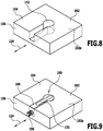
- the one or more anchoring sections 148 project in particular from the base section 146 in one or more directions perpendicular to the connecting direction 124, so that the base body 104 can be fixed in a component 102 in a form-fitting manner in a recess 152 which is complementary to the base body 104 (see in particular FIG 8 and 9 ).
- the recess 152 is preferably arranged and / or formed in a component 102 such that the recess 152 extends both in a main side 154 and in a narrow side 156 of the component 102.
- the orientation of the recess 152 is preferably selected such that the connection direction 124 is at least approximately perpendicular to the narrow side 156.
- the recess 152 and the base body 104 are preferably complementary to each other, so that the recess 152 can be essentially completely filled by means of the base body 104.
- An outer side 158 of the base body 104 facing away from the receiving channel 106 is preferably provided with one or more anchoring ribs 160.
- the anchoring ribs 160 are, in particular, line-shaped barbs which allow the introduction of the base body 104 into the recess 152, but make it more difficult to remove the base body 104 from the recess 152.
- the tapered section 118 of the base body 104 comprises one or more holding projections 162, for example holding ribs 164.
- the inner diameter D I of the tapered section 118 is locally reduced, so that in particular a threaded section 126 of a fastening element 108 designed as a screw 120 can be received in the tapered section 118 by clamping or latching.
- the fastening element 108 can be held on the base body 104 and in particular secured against undesired falling out of the base body 104.
- a connecting means 100 works in particular as follows: Two components 102 to be connected to one another are preferably prepared by making a cutout 152 in a first component 102a (see in particular FIG Fig. 8 ).
- the shape of the recess 152 is, in particular, complementary to the shape of the base body 104 of the connecting means 100, so that the base body 104 can be fixed in the recess 152 in a form-fitting manner.
- the form fit relates in particular to the connection direction 124, in which a force later connecting the two components 102 acts.
- the recess 152 is introduced into the first component 102a, for example by means of a milling machine.
- a second component 102b is provided, for example, with a bore 166 (see in particular Fig. 11 ).
- the connecting means 100 is preferably prepared for the assembly of the same and the components 102 in that the fastening element 108, which is designed, for example, as a screw 120, is introduced through the insertion opening 112 into the receiving channel 106 of the base body 104.
- the fastening element 108 is in particular pushed so far through the receiving channel 106 until the fastening element 108 also comes into engagement with the holding projections 162 and is thereby held securely on the base body 104.
- the base body 104 is then introduced together with the fastening element 108 into the recess 152 of the first component 102a.
- the two components 102 are then arranged in the desired position to be fixed by means of the connecting means 100.
- a threaded section 126 of the fastening element 108 designed as a screw 120 protruding from the fixing opening 116 can already be inserted in sections into the bore 166 of the second component 102b.
- the tool 134 is passed through the actuation opening 132 and brought into engagement with the engagement section 136 of the fastening element 108.
- the fastening element 108 can then be set in rotation by rotating the tool 134.
- the fastening element 108 is thereby screwed into the bore 166 of the second component 102b.
- the two components 102 are thereby firmly connected to one another.
- a force transmission along the connecting direction 124 then takes place on the one hand between the second component 102b and the threaded section 126 of the fastening element 108 designed as a screw and on the other hand between the anchoring section 148 of the base body 104 and the recess 152 in the first component 102a.
- the power transmission between the base body and the fastening element 108 takes place between the screw head 122 and the tapering section 118.
- the forces acting on the first component 102a can be transmitted at a large distance from the narrow side 156.
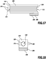
- the illustrated second embodiment of a connecting means 100 differs from that in FIGS 1 to 12 First embodiment shown essentially in that the end face 128 of the base body 104 is oriented obliquely to the connection direction 124.
- the connecting means 100 according to that in FIGS 13 and 14
- the second embodiment shown is particularly suitable for connecting two mitered components 102.
- the end face 128 of the base body 104 is inclined at 45 ° to the connection 124, so that the connecting means 100 is particularly suitable for connecting two components 102 to be arranged at a 90 ° angle to one another if these components 102 are each provided with a 45 ° miter are.
- the illustrated third embodiment of a connecting means 100 differs from that in FIGS 1 to 12 First embodiment shown essentially in that the base body 104 has an anchoring bolt 168 instead of the cylindrical thickening 150.
- the anchoring bolt 168 extends in particular perpendicularly to a main side 154 of the first component 102a, in which the base body 104 can be fixed, away from the base section 146 of the base body 104.
- the anchoring bolt 168 is preferably arranged on the end 110 of the base body 104 facing away from the fixing opening 116.
- the base body 104 comprises one or more, for example four, positioning projections 170.
- the positioning projections 170 are arranged in particular on the end face 128 of the base body 104 and form, for example, an annular extension of the fixing opening 116 and / or the tapering section 118.
- the positioning projections 170 are used in particular to position the base body 104 independently of the fastening element 108 relative to a bore 166 in the second component 102b, in that the positioning projections 170 already align the components 102 with respect to one another before the fastening element 108 is fixed in the bore 166 of the second component 102b are introduced.
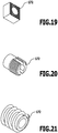
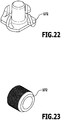
- the counterparts 172 shown are used in particular individually in combination with a base body 104 and a fastening element 108 if the fastening element 108 is not to be fixed directly to the second component 102b for any reason.
- one of the counterparts 172 or a counterpart 172, not shown, is fixed on the second component 102b, for example screwed, locked, glued, etc.
- the fastening element 108 then does not act directly on the second component 102b in order to connect the two components 102 to one another. Rather, the fastening element 108 is then preferably brought into engagement with the counterpart 172 in and / or on the second component 102b.
- the counterpart 172 can for example be a slide-in plate (see Fig. 19 ), an impact sleeve (see Fig. 20 ), a ramp socket (see Fig. 21 ), a driving nut (see Fig. 22 ) or a single nut (see Fig. 23 ) be.
- the fourth embodiment of a connecting means 100 illustrated differs from that in FIGS 1 to 12 First embodiment shown essentially in that two expansion elements 200 of an expansion device 201 are provided.
- the spreading elements 200 are, in particular, pivoting elements 202 which are formed in one piece with the base body 104 and are fixed, in particular pivotable, on the base body 104 with respect to the receiving channel 106.
- the expansion elements 200 are in particular on the one hand in the in Fig. 24 shown starting position and on the other hand in the Fig. 25 shown spread position can be arranged.
- the expansion elements 200 protrude particularly into the receiving channel 106 (see in particular Fig. 28 ).
- the spreading elements 200 are moved outward from the receiving channel 106 by means of the screw head 122 of the fastening element 108 designed as a screw 120.
- the spreading elements 200 thus protrude in the spreading position over an outer contour of the base body 104.
- the expansion elements 200 are pressed into the component 102 by means of the fastening element 108.
- the expansion elements 200 are formed, for example, by C-shaped recesses 204 in side walls 206 of the base body 104.
- C-shaped separation slots 208 are provided in the base body 104 in order to form the expansion elements 200.
- the expansion elements 200 preferably each comprise one or more inclined surfaces 210 on which the fastening element 108, in particular the screw head 122, engages to bring the spreading elements 200 from the starting position into the spreading position.
- the spreading elements 200 are preferably elastically flexible and / or arranged.
- the spreading elements 200 When the fastening element 108 is removed from the fixing opening 116, the spreading elements 200 thus preferably automatically move back from the spreading position into the starting position.
- FIGS 1 to 12 The fifth embodiment of a connecting means 100 illustrated differs from that in FIGS 1 to 12 First embodiment shown essentially in that the connecting means 100 comprises several, for example three or four, anchoring sections 148, which are in particular formed as at least sectionally cylindrical thickenings 150.
- the anchoring sections 148 preferably overlap in such a way that the base body 104 is, for example, cloud-shaped in a cross section.
- Anchoring ribs 160 are in the in Fig. 30 fifth embodiment of the connecting means 100 shown is not provided. However, in a further embodiment (not shown), the one in FIG Fig. 30 cloud shape shown may be provided in combination with anchoring ribs 160.
- FIG. 31 The sixth embodiment of a connecting means 100 illustrated differs from that in FIG Fig. 30 fifth embodiment shown essentially in that the base body 104 is provided with anchoring ribs 160.
- the base body 104 comprises a cover section 212, by means of which in particular an edge of the recess 152 in a component 102 can be covered.
- the cover section 212 is designed in particular as a laterally projecting collar 214 on the base body 104.
- the cover section 212 in particular the collar 214, has in particular a geometrically simpler shape than the anchoring sections 148 of the base body 104, as a result of which in particular an aesthetic appearance of the connecting means 100 can be achieved in the assembled state thereof.
- the connecting means 100 shown provided that the actuating opening 132 is at least partially and / or at least approximately complementary to an outer contour of the fastening element 108.
- the actuation opening 132 comprises a narrow slot section 216 and a section 218 which is wider in comparison to this.
- the slot section 216 and the wider section 218 are designed in particular in such a way that a fastening element 108 in the form of a screw 120 can be introduced into the receiving channel 106 through the actuating opening 132.
- the insertion opening 112 is in the in Fig. 31
- the sixth embodiment of the connecting means 100 shown is thus optional.
- the third embodiment of the connecting means 100 shown here has an obliquely oriented end face 128 according to that in FIGS 13 and 14 second embodiment shown may be provided.
- a collar 214 and / or cover section 212 may be provided for covering an edge region of the recess 152 arranged in the component 102.
Abstract
Um ein Verbindungsmittel zur Verbindung zweier Bauteile bereitzustellen, welches einfach herstellbar ist und eine stabile und zuverlässige Verbindung der zwei Bauteile ermöglicht, wird vorgeschlagen, dass das Verbindungsmittel einen Grundkörper umfasst, welcher einen sich durch den Grundkörper hindurch erstreckenden Aufnahmekanal zur Aufnahme eines Befestigungselements umfasst, wobei der Aufnahmekanal vorzugsweise an einem Ende durch eine Einbringöffnung des Grundkörpers und/oder vorzugsweise an einem (weiteren) Ende durch eine Festlegungsöffnung des Grundkörpers zugänglich ist, wobei der Grundkörper vorzugsweise ferner eine von der Einbringöffnung und/oder der Festlegungsöffnung verschiedene Betätigungsöffnung umfasst, durch welche insbesondere das im Aufnahmekanal angeordnete Befestigungselement vorzugsweise zur Betätigung desselben zugänglich ist.In order to provide a connecting means for connecting two components, which is simple to manufacture and enables a stable and reliable connection of the two components, it is proposed that the connecting means comprise a base body, which comprises a receiving channel extending through the base body for receiving a fastening element, wherein the receiving channel is preferably accessible at one end through an insertion opening of the base body and / or preferably at a (further) end through a fixing opening of the base body, the base body preferably further comprising an actuation opening different from the insertion opening and / or the fixing opening, through which in particular the fastening element arranged in the receiving channel is preferably accessible for actuating the same.
Description
Die vorliegende Erfindung betrifft ein Verbindungsmittel, welches insbesondere im Möbel- und Maschinenbau zum Einsatz kommt. Mittels des Verbindungsmittels sind insbesondere zwei Bauteile eines Möbelstücks oder zwei Bauteile einer Maschine miteinander verbindbar.The present invention relates to a connecting means which is used in particular in furniture and mechanical engineering. In particular, two components of a piece of furniture or two components of a machine can be connected to one another by means of the connecting means.
Der vorliegenden Erfindung liegt die Aufgabe zugrunde, ein Verbindungsmittel zur Verbindung zweier Bauteile bereitzustellen, welches einfach herstellbar ist und eine stabile und zuverlässige Verbindung der zwei Bauteile ermöglicht.The present invention has for its object to provide a connecting means for connecting two components, which is easy to manufacture and enables a stable and reliable connection of the two components.
Diese Aufgabe wird erfindungsgemäß durch ein Verbindungsmittel zur Verbindung zweier Bauteile gelöst, wobei das Verbindungsmittel einen Grundkörper umfasst, welcher einen sich durch den Grundkörper hindurcherstreckenden Aufnahmekanal zur Aufnahme eines Befestigungselements umfasst, wobei der Aufnahmekanal vorzugsweise an einem Ende durch eine Einbringöffnung des Grundkörpers und/oder vorzugsweise an einem (weiteren) Ende durch eine Festlegungsöffnung des Grundkörpers zugänglich ist, wobei der Grundkörper ferner eine von der Einbringöffnung und/oder der Festlegungsöffnung verschiedene Betätigungsöffnung umfasst, durch welche insbesondere das im Aufnahmekanal angeordnete Befestigungselement vorzugsweise zur Betätigung desselben zugänglich ist.This object is achieved according to the invention by a connecting means for connecting two components, the connecting means comprising a base body which comprises a receiving channel extending through the base body for receiving a fastening element, the receiving channel preferably at one end through an insertion opening of the base body and / or preferably is accessible at a (further) end through a fixing opening of the base body, the base body further comprising an actuating opening that is different from the insertion opening and / or the fixing opening, through which in particular the fastening element arranged in the receiving channel is preferably accessible for actuating the same.
Dadurch, dass der Grundkörper eine Einbringöffnung und/oder eine Festlegungsöffnung umfasst, kann das Befestigungselement vorzugsweise einfach und sicher in dem Grundkörper angeordnet und an demselben festgelegt werden. Dadurch, dass der Grundkörper ferner vorzugsweise eine von der Einbringöffnung und/oder der Festlegungsöffnung verschiedene Betätigungsöffnung umfasst, kann das Befestigungselement vorzugsweise durch eine besonders schmale und/oder optisch ansprechende Zugangsöffnung hindurch betätigt werden.Because the base body comprises an insertion opening and / or a fixing opening, the fastening element can preferably be arranged simply and securely in the base body and on the same be determined. Due to the fact that the base body preferably also comprises an actuation opening that differs from the insertion opening and / or the fixing opening, the fastening element can preferably be actuated through a particularly narrow and / or visually appealing access opening.
Insbesondere kann durch die Kombination aus Einbringöffnung, Festlegungsöffnung und Betätigungsöffnung eine komfortable Handhabung des Verbindungsmittels sowie eine zuverlässige und stabile Verbindung der zwei Bauteile ermöglicht werden.In particular, the combination of insertion opening, fixing opening and actuation opening enables comfortable handling of the connecting means as well as a reliable and stable connection of the two components.
Die Einbringöffnung des Grundkörpers dient vorzugsweise dem Einbringen des Befestigungselements in den Aufnahmekanal.The insertion opening of the base body is preferably used to insert the fastening element into the receiving channel.
Es kann jedoch auch vorgesehen sein, dass das Befestigungselement durch die Betätigungsöffnung hindurch in den Aufnahmekanal einbringbar ist.However, it can also be provided that the fastening element can be introduced into the receiving channel through the actuating opening.
Die Betätigungsöffnung ist dann vorzugsweise zugleich die Einbringöffnung.The actuation opening is then preferably also the insertion opening.
Die Betätigungsöffnung ist vorzugsweise zumindest abschnittsweise und/oder zumindest näherungsweise komplementär zu einer Außenkontur des Befestigungselements ausgebildet.The actuating opening is preferably designed at least in sections and / or at least approximately complementarily to an outer contour of the fastening element.
Beispielsweise kann vorgesehen sein, dass die Betätigungsöffnung einen schmalen Schlitzabschnitt und einen im Vergleich hierzu breiteren Abschnitt umfasst, durch welchen insbesondere ein Schraubenkopf eines als Schraube ausgebildeten Befestigungselements in den Aufnahmekanal einbringbar ist.For example, it can be provided that the actuating opening comprises a narrow slot section and a section which is wider by comparison, through which, in particular, a screw head of a fastening element designed as a screw can be inserted into the receiving channel.
Die Festlegungsöffnung des Grundkörpers dient vorzugsweise der Festlegung des Befestigungselements einerseits an dem Grundkörper und andererseits an einem weiteren Bauteil.The fixing opening of the base body preferably serves to fix the fastening element on the one hand on the base body and on the other hand on another component.
Das Befestigungselement ragt vorzugsweise im montierten Zustand des Verbindungsmittels teilweise aus der Festlegungsöffnung heraus.The fastening element preferably partially protrudes from the fixing opening in the assembled state of the connecting means.
Insbesondere kann vorgesehen sein, dass das Befestigungselement im montierten Zustand des Verbindungsmittels die Festlegungsöffnung des Grundkörpers an deren dem Aufnahmekanal zugewandten Innenseite hintergreift.In particular, it can be provided that the fastening element engages behind the fixing opening of the base body on its inner side facing the receiving channel when the connecting means is in the assembled state.
Die Betätigungsöffnung ist vorzugsweise als ein Betätigungsschlitz ausgebildet.The actuation opening is preferably designed as an actuation slot.
Die Einbringöffnung und/oder die Festlegungsöffnung weisen vorzugsweise jeweils einen senkrecht zu einer Verbindungsrichtung des Verbindungselements genommenen im Wesentlichen kreisförmigen Querschnitt auf.The insertion opening and / or the fixing opening preferably each have an essentially circular cross section taken perpendicular to a connecting direction of the connecting element.
Günstig kann es sein, wenn der Grundkörper einstückig ausgebildet ist.It can be favorable if the base body is formed in one piece.
Beispielsweise kann vorgesehen sein, dass der Grundkörper als ein Kunststoff-Spritzgussbauteil oder als ein Metall-Druckgussbauteil ausgebildet ist.For example, it can be provided that the base body is designed as a plastic injection-molded component or as a metal die-cast component.
Vorteilhaft kann es sein, wenn das Befestigungselement eine Schraube ist.It can be advantageous if the fastening element is a screw.
Hierbei kann vorgesehen sein, dass die Einbringöffnung größer ist als ein Schraubenkopf der Schraube.It can be provided here that the insertion opening is larger than a screw head of the screw.
Alternativ oder ergänzend hierzu kann vorgesehen sein, dass die Festlegungsöffnung kleiner ist als der Schraubenkopf der Schraube.Alternatively or in addition to this, it can be provided that the fixing opening is smaller than the screw head of the screw.
Ferner kann alternativ oder ergänzend hierzu vorgesehen sein, dass die Festlegungsöffnung größer ist als ein Gewindeabschnitt der Schraube.Furthermore, it can alternatively or additionally be provided that the fixing opening is larger than a threaded portion of the screw.
Unter der Formulierung "größer" und "kleiner" ist in dieser Beschreibung und den beigefügten Ansprüchen insbesondere zu verstehen, dass das jeweilige Element (Schraubenkopf, Gewindeabschnitt) durch die Öffnung hindurchführbar ist (Öffnung größer als das genannte Element) oder eben nicht durch die Öffnung hindurchführbar ist (Öffnung kleiner als das genannte Element).The wording "larger" and "smaller" in this description and the appended claims is to be understood in particular to mean that the respective Element (screw head, threaded section) can be passed through the opening (opening larger than said element) or just cannot be passed through the opening (opening smaller than said element).
Vorteilhaft kann es sein, wenn die Festlegungsöffnung einen oder mehrere radial nach innen ragende Vorsprünge umfasst, welche insbesondere mit einem Gewindeabschnitt eines als Schraube ausgebildeten Befestigungselements in Eingriff bringbar sind.It can be advantageous if the fixing opening comprises one or more radially inwardly projecting projections, which can in particular be brought into engagement with a threaded section of a fastening element designed as a screw.
Das Befestigungselement ist dann insbesondere in einem montagebereiten Zustand an dem Grundkörper gegen ein Herausfallen gesichert.The fastening element is then secured against falling out, in particular in a ready-to-install state on the base body.
Bei einer Ausgestaltung der Erfindung kann vorgesehen sein, dass die Betätigungsöffnung in mindestens einer Richtung kleiner ist als ein senkrecht zu einer Verbindungsrichtung des Befestigungselements genommener maximaler, minimaler und/oder durchschnittlicher Außendurchmesser des Befestigungselements, insbesondere eines Schraubenkopfs und/oder eines Gewindeabschnitts eines als Schraube ausgebildeten Befestigungselements.In one embodiment of the invention, it can be provided that the actuation opening is smaller in at least one direction than a maximum, minimum and / or average outer diameter of the fastening element, in particular a screw head and / or a threaded section of a screw, which is taken perpendicular to a connecting direction of the fastening element Fastener.
Die Verbindungsrichtung ist vorzugsweise parallel zu einer Einbringrichtung des Befestigungselements, in welcher das Befestigungselement durch die Einbringöffnung hindurch in den Aufnahmekanal einführbar ist.The connection direction is preferably parallel to an insertion direction of the fastening element, in which the fastening element can be inserted into the receiving channel through the insertion opening.
Vorzugsweise ist die Verbindungsrichtung parallel zu einer Haupterstreckungsrichtung des Aufnahmekanals.The connection direction is preferably parallel to a main direction of extent of the receiving channel.
Günstig kann es sein, wenn die Verbindungsrichtung parallel zu einer Rotationsachse des Befestigungselements ist. Das Befestigungselement ist vorzugsweise im Wesentlichen rotationssymmetrisch um die Rotationsachse ausgebildet.It can be favorable if the connection direction is parallel to an axis of rotation of the fastening element. The fastening element is preferably essentially rotationally symmetrical about the axis of rotation.
Ferner kann vorgesehen sein, dass die Rotationsachse des Befestigungselements diejenige Achse ist, um welche das Befestigungselement zur Festlegung desselben an dem weiteren Bauteil drehbar ist oder gedreht wird.Furthermore, it can be provided that the axis of rotation of the fastening element is the axis about which the fastening element can be rotated or is rotated to fix it on the further component.
Beispielsweise kann vorgesehen sein, dass die Verbindungsrichtung im Wesentlichen parallel zu einer Haupterstreckungsrichtung einer als Betätigungsschlitz ausgebildeten Betätigungsöffnung ist.For example, it can be provided that the connection direction is substantially parallel to a main direction of extension of an actuation opening designed as an actuation slot.
Die Verbindungsrichtung ist vorzugsweise eine Befestigungsrichtung, in welcher eine mittels des Verbindungsmittels zwischen den zwei Bauteilen wirkende Kraft ausgerichtet ist.The connecting direction is preferably a fastening direction in which a force acting between the two components by means of the connecting means is oriented.
Es kann vorgesehen sein, dass das Befestigungselement einen Angriffsabschnitt umfasst, an welchem ein Benutzer des Verbindungsmittels zur Betätigung des Befestigungselements mittels eines Werkzeugs angreifen kann.It can be provided that the fastening element comprises an engagement section on which a user of the connecting means for actuating the fastening element can engage by means of a tool.
Vorzugsweise bildet das Werkzeug zur Betätigung des Befestigungselements zusammen mit dem Angriffsabschnitt ein Winkelgetriebe.The tool for actuating the fastening element preferably forms an angular gear together with the engagement section.
Der Angriffsabschnitt ist hierzu insbesondere als ein männliches oder weibliches Element einer Sechskantverbindung oder Sechsrundverbindung ausgebildet.For this purpose, the attack section is designed in particular as a male or female element of a hexagonal connection or hexagonal connection.
Vorzugsweise ist der Angriffsabschnitt an einem Schraubenkopf eines als Schraube ausgebildeten Befestigungselements angeordnet und/oder ausgebildet.The engagement section is preferably arranged and / or formed on a screw head of a fastening element designed as a screw.
Der männliche Teil der Verbindung ist vorzugsweise als ein Rundkopf ausgebildet, insbesondere um das Befestigungselement auch bei schräger Ausrichtung des Werkzeugs betätigen zu können.The male part of the connection is preferably designed as a round head, in particular in order to be able to actuate the fastening element even when the tool is inclined.
Günstig kann es sein, wenn der Grundkörper einen beispielsweise quaderförmigen Basisabschnitt und einen oder mehrere von dem Basisabschnitt wegragende oder hervorstehende Verankerungsabschnitte zur Verankerung des Grundkörpers in einem der Bauteile umfasst.It can be expedient if the base body has, for example, a cuboid base section and one or more of the base section protruding or protruding anchoring sections for anchoring the base body in one of the components.
Mindestens ein Verankerungsabschnitt ist vorzugsweise als eine zylinderförmige Verdickung eines der Festlegungsöffnung abgewandten Endes des Grundkörpers ausgebildet.At least one anchoring section is preferably designed as a cylindrical thickening of an end of the base body facing away from the fixing opening.
Mindestens ein Verankerungsabschnitt kann beispielsweise als ein senkrecht oder schräg zu einer Verbindungsrichtung des Verbindungsmittels von dem Basisabschnitt wegragender Verankerungsbolzen ausgebildet sein.At least one anchoring section can be designed, for example, as an anchoring bolt projecting perpendicularly or obliquely to a connecting direction of the connecting means from the base section.
Es kann vorgesehen sein, dass die Betätigungsöffnung sich in einer parallel zu einer Verbindungsrichtung des Verbindungsmittels verlaufenden Richtung über mindestens ungefähr ein Drittel, insbesondere mindestens ungefähr die Hälfte, einer in der Verbindungsrichtung genommenen Länge des Grundkörpers erstreckt.It can be provided that the actuating opening extends in a direction running parallel to a connecting direction of the connecting means over at least about a third, in particular at least about half, of a length of the base body taken in the connecting direction.
Insbesondere kann vorgesehen sein, dass sich die Betätigungsöffnung in einer parallel zu einer Verbindungsrichtung des Verbindungsmittels verlaufenden Richtung über mindestens ungefähr zwei Drittel einer in der Verbindungsrichtung genommenen Länge des Grundkörpers erstreckt.In particular, it can be provided that the actuating opening extends in a direction running parallel to a connecting direction of the connecting means over at least approximately two thirds of a length of the base body taken in the connecting direction.
Eine dem Aufnahmekanal abgewandte Außenseite des Grundkörpers ist vorzugsweise zumindest abschnittsweise mit einem oder mehreren Verankerungselementen, insbesondere Verankerungsrippen, zur Verankerung des Grundkörpers in einem Bauteil versehen.An outside of the base body facing away from the receiving channel is preferably provided at least in sections with one or more anchoring elements, in particular anchoring ribs, for anchoring the base body in a component.
Insbesondere ist mittels der Verankerungsrippen eine Verankerung in einer senkrecht zur Verbindungsrichtung genommenen Richtung möglich.In particular, anchoring in a direction taken perpendicular to the connection direction is possible by means of the anchoring ribs.
Es kann jedoch auch vorgesehen sein, dass mittels der Verankerungsrippen eine Verankerung des Grundkörpers in einer parallel zur Verbindungsrichtung verlaufenden Richtung erzielt wird.However, it can also be provided that the anchoring ribs are used to anchor the base body in a direction running parallel to the connecting direction.
Vorteilhaft kann es sein, wenn das Verbindungsmittel zusätzlich zu dem Befestigungselement und dem in einem ersten der zwei Bauteile anordenbaren Grundkörper ein an einem zweiten der zwei Bauteile festlegbares Gegenstück umfasst. Zur Verbindung der zwei Bauteile ist das Befestigungselement vorzugsweise ausgehend von dem Grundkörper mit dem Gegenstück in Eingriff bringbar, beispielsweise verschraubbar.It may be advantageous if, in addition to the fastening element and the base body which can be arranged in a first of the two components, the connecting means comprises a counterpart which can be fixed on a second of the two components. To connect the two components, the fastening element can preferably be brought into engagement with the counterpart, for example screwed, starting from the base body.
Der Grundkörper umfasst vorzugsweise eine, zwei oder mehr Positioniervorsprünge, welche sich insbesondere in einem Bereich der Festlegungsöffnung in der Verbindungsrichtung von dem Grundkörper weg erstrecken.The base body preferably comprises one, two or more positioning projections, which extend in particular in a region of the fixing opening in the connection direction away from the base body.
Die Positioniervorsprünge sind insbesondere in eine Bohrung oder ein Gegenstück in dem zweiten Bauteil führbar, um eine einfache Relativpositionierung der zwei Bauteile vor der Festlegung des Befestigungselements zu ermöglichen.The positioning projections can in particular be guided into a bore or a counterpart in the second component in order to enable simple relative positioning of the two components before the fastening element is fixed.
Das Verbindungsmittel eignet sich insbesondere zur Verwendung in Kombination mit zwei Bauteilen. Eines der Bauteile weist vorzugsweise eine einer Außenform des Grundkörpers des Verbindungsmittels entsprechende Ausnehmung auf, so dass der Grundkörper formschlüssig in dem Bauteil festlegbar ist.The connecting means is particularly suitable for use in combination with two components. One of the components preferably has a recess corresponding to an outer shape of the base body of the connecting means, so that the base body can be positively fixed in the component.
Die erfindungsgemäße Kombination weist vorzugsweise einzelne oder mehrere der im Zusammenhang mit dem erfindungsgemäßen Verbindungsmittel beschriebenen Merkmale und/oder Vorteile auf.The combination according to the invention preferably has one or more of the features and / or advantages described in connection with the connecting means according to the invention.
Die Ausnehmung in dem einen der Bauteile ist vorzugsweise sowohl von einer Hauptseite des beispielsweise plattenförmigen Bauteils als auch von einer Schmalseite dieses Bauteils zugänglich.The recess in one of the components is preferably accessible both from a main side of the plate-shaped component, for example, and from a narrow side of this component.
Im montierten Zustand des Verbindungsmittels erstreckt sich das Befestigungselement vorzugsweise über die Schmalseite des Bauteils hinaus und/oder in das weitere Bauteil hinein.In the assembled state of the connecting means, the fastening element preferably extends beyond the narrow side of the component and / or into the further component.
Die Bauteile sind vorzugsweise Möbelteile oder Maschinenteile.The components are preferably furniture parts or machine parts.
Der Grundkörper des Verbindungsmittels kann beispielsweise durch Presspassung und/oder mittels einer Klebeverbindung an und/oder in einem der Bauteile festgelegt werden.The base body of the connecting means can be fixed on and / or in one of the components, for example, by a press fit and / or by means of an adhesive connection.
Alternativ oder ergänzend hierzu kann vorgesehen sein, dass der Grundkörper mittels einer Schraubverbindung, mittels eines oder mehrerer Einschlagbolzen, mittels einer Schwalbenschwanzverbindung und/oder mittels eines oder mehrerer Zapfen an und/oder in einem der beiden Bauteile festlegbar ist.As an alternative or in addition to this, it can be provided that the base body can be fixed on and / or in one of the two components by means of a screw connection, by means of one or more drive-in bolts, by means of a dovetail connection and / or by means of one or more pins.
Das Werkzeug zum Betätigen des Befestigungselements ist vorzugsweise unmittelbar mit dem Befestigungselement in Eingriff bringbar.The tool for actuating the fastening element can preferably be brought directly into engagement with the fastening element.
Zum Verbinden der zwei Bauteile kann das Befestigungselement beispielsweise mittels des Grundkörpers an dem einen Bauteil festgelegt werden und unmittelbar oder mittelbar an dem weiteren Bauteil angreifen und/oder mit dem weiteren Bauteil in Eingriff gebracht werden.To connect the two components, the fastening element can, for example, be fixed on the one component by means of the base body and act directly or indirectly on the further component and / or be brought into engagement with the further component.
Ein als Schraube ausgebildetes Befestigungselement kann beispielsweise hinsichtlich eines Schraubenkopfs und/oder eines Gewindeabschnitts eine Torx-Schraube, eine Inbus-Schraube, eine Euroschraube, eine Spax-Schraube oder eine Schraube mit M-Gewinde sein.A fastening element designed as a screw can be, for example, a Torx screw, an Allen screw, a Euro screw, a Spax screw or a screw with an M thread with regard to a screw head and / or a thread section.
Insbesondere im Falle einer mittelbaren Festlegung des Befestigungselements an und/oder in dem weiteren Bauteil ist in und/oder an dem weiteren Bauteil vorzugsweise ein Gegenstück angeordnet, insbesondere festgelegt. An diesem Gegenstück greift das Befestigungselement vorzugsweise an.In particular in the case of an indirect fixing of the fastening element on and / or in the further component, a counterpart is preferably arranged, in particular fixed, in and / or on the further component. The fastening element preferably engages this counterpart.
Das Gegenstück kann beispielsweise eine Einschiebeplatte, eine Einschlagmuffe, eine Rampamuffe, eine Einschlagmutter oder eine Einleimmutter sein.The counterpart can be, for example, a slide-in plate, a drive-in sleeve, a ramp sleeve, a drive-in nut or a drive-in nut.
Die vorliegende Erfindung betrifft ferner ein Verfahren zum Verbinden zweier Bauteile.The present invention further relates to a method for connecting two components.
Der Erfindung liegt diesbezüglich die Aufgabe zugrunde, ein Verfahren zum Verbinden zweier Bauteile bereitzustellen, welches einfach durchführbar ist und eine stabile und zuverlässige Verbindung zweier Bauteile ermöglicht.In this regard, the invention is based on the object of providing a method for connecting two components which is simple to carry out and enables a stable and reliable connection of two components.
Diese Aufgabe wird erfindungsgemäß dadurch gelöst, dass das Verfahren zum Verbinden zweier Bauteile Folgendes umfasst:
- Bereitstellen eines Bauteils, insbesondere eines plattenförmigen Bauteils;
- Einbringen einer Ausnehmung durch Bearbeitung des Bauteils, insbesondere mittels einer Fräsmaschine, bei welcher ein Fräskopf um eine senkrecht zu einer Hauptseite des Bauteils, insbesondere einer Hauptseite des plattenförmigen Bauteils, verlaufende Rotationsachse gedreht wird;
- Einbringen eines Grundkörpers eines Verbindungsmittels in die Ausnehmung, insbesondere Einbringen eines Grundkörpers eines erfindungsgemäßen Verbindungsmittels in die Ausnehmung;
- Verbinden der Bauteile miteinander durch Betätigen eines in dem Grundkörper angeordneten Befestigungselements des Verbindungsmittels.
- Providing a component, in particular a plate-shaped component;
- Making a recess by machining the component, in particular by means of a milling machine, in which a milling head is rotated about an axis of rotation running perpendicular to a main side of the component, in particular a main side of the plate-shaped component;
- Introducing a base body of a connecting means into the recess, in particular inserting a base body of a connecting means according to the invention into the recess;
- Connecting the components to one another by actuating a fastening element of the connecting means arranged in the base body.
Das erfindungsgemäße Verfahren weist vorzugsweise einzelne oder mehrere der im Zusammenhang mit dem erfindungsgemäßen Verbindungsmittel beschriebenen Merkmale und/oder Vorteile auf.The method according to the invention preferably has one or more of the features and / or advantages described in connection with the connecting means according to the invention.
Günstig kann es sein, wenn das Befestigungselement in den Grundkörper eingebracht wird, bevor der Grundkörper in der Ausnehmung des Bauteils angeordnet wird.It can be expedient if the fastening element is introduced into the base body before the base body is arranged in the recess in the component.
Das Befestigungselement wird vorzugsweise durch eine Einbringöffnung des Grundkörpers in den Grundkörper eingebracht. Die Einbringöffnung ist in einem montierten Zustand des Grundkörpers, in welcher dieser in der Ausnehmung des Bauteils angeordnet ist, vorzugsweise unzugänglich.The fastening element is preferably introduced into the base body through an insertion opening of the base body. The insertion opening is in an assembled state of the base body, in which it is arranged in the recess of the component, preferably inaccessible.
Vorzugsweise sind im montierten Zustand des Grundkörpers, in welchem dieser in der Ausnehmung des Bauteils angeordnet ist, eine Festlegungsöffnung des Grundkörpers und eine Betätigungsöffnung des Grundkörpers zugänglich.In the assembled state of the base body, in which it is arranged in the recess of the component, a fixing opening of the base body and an actuation opening of the base body are preferably accessible.
Das Befestigungselement ragt vorzugsweise durch die Festlegungsöffnung aus dem Grundkörper heraus, ist dabei jedoch vorzugsweise aufgrund eines Hinterschnittes formschlüssig in dem Grundkörper gehalten.The fastening element preferably protrudes from the base body through the fixing opening, but is preferably held in a form-fitting manner in the base body due to an undercut.
Sowohl die Festlegungsöffnung als auch die Betätigungsöffnung sind vorzugsweise in mindestens einer Erstreckungsrichtung kleiner als ein maximaler Außendurchmesser des Befestigungselements, insbesondere bezüglich einer Symmetrieachse oder Rotationsachse oder Längsachse des Befestigungselements.Both the fixing opening and the actuating opening are preferably smaller than a maximum outer diameter of the fastening element in at least one direction of extension, in particular with respect to an axis of symmetry or axis of rotation or longitudinal axis of the fastening element.
Das Befestigungselement ist vorzugsweise weder durch die Festlegungsöffnung noch durch die Betätigungsöffnung hindurch aus dem Grundkörper entnehmbar.The fastening element can preferably be removed from the base body neither through the fixing opening nor through the actuating opening.
Die Ausnehmung und/oder der Grundkörper des Verbindungsmittels sind vorzugsweise so geformt, dass mittels des Grundkörpers die in dem Bauteil vorgesehene Ausnehmung im Wesentlichen vollständig mit dem Grundkörper aufgefüllt wird oder auffüllbar ist.The recess and / or the base body of the connecting means are preferably shaped such that the recess provided in the component is essentially completely filled with the base body or can be filled by means of the base body.
Die Ausnehmung erstreckt sich vorzugsweise sowohl in einer Hauptseite des Bauteils als auch in einer Nebenseite, insbesondere einer Schmalseite, des Bauteils. Vorzugsweise ist eine Verbindungsrichtung des Verbindungsmittels senkrecht zu einer Nebenseite, insbesondere einer Schmalseite, des Bauteils ausgerichtet.The recess preferably extends both in a main side of the component and in a secondary side, in particular a narrow side, of the component. A connecting direction of the connecting means is preferably oriented perpendicular to an auxiliary side, in particular a narrow side, of the component.
Es kann jedoch auch eine schräge Ausrichtung der Verbindungsrichtung relativ zu der Schmalseite vorgesehen sein.However, an oblique orientation of the connection direction relative to the narrow side can also be provided.
Eine Stirnseite des Grundkörpers, in welcher die Festlegungsöffnung angeordnet ist, ist beispielsweise im Wesentlichen senkrecht zur Verbindungsrichtung ausgerichtet.An end face of the base body, in which the fixing opening is arranged, is oriented essentially perpendicular to the connection direction, for example.
Ferner kann vorgesehen sein, dass die Stirnseite, in welcher die Festlegungsöffnung angeordnet ist, mit der Verbindungsrichtung einen Winkel von beispielsweise ungefähr 45° einschließt. Hierdurch kann das Verbindungsmittel insbesondere zum Verbinden zweier mit Gehrung versehener Platten verwendet werden.Furthermore, it can be provided that the end face, in which the fixing opening is arranged, encloses an angle of, for example, approximately 45 ° with the connecting direction. As a result, the connecting means can be used in particular for connecting two mitred plates.
Das Befestigungselement ist vorzugsweise drehbar um eine parallel zur Verbindungsrichtung verlaufende Rotationsachse in dem Grundkörper gelagert und/oder aufgenommen.The fastening element is preferably mounted and / or accommodated in the base body about an axis of rotation running parallel to the connecting direction.
Beispielsweise ein als Schraube ausgebildetes Befestigungselement kann durch Drehen desselben mittels eines Werkzeugs unmittelbar in das zweite Bauteil eingeschraubt werden. Alternativ hierzu kann vorgesehen sein, dass das Befestigungselement in ein an und/oder in dem zweiten Bauteil angeordnetes Gegenstück einschraubbar ist.For example, a fastening element designed as a screw can be screwed directly into the second component by turning it using a tool. As an alternative to this, it can be provided that the fastening element can be screwed into a counterpart arranged on and / or in the second component.
Das Befestigungselement ist vorzugsweise durch die Betätigungsöffnung zugänglich, um das Befestigungselement mittels eines Werkzeugs in eine Drehbewegung zu versetzen.The fastening element is preferably accessible through the actuation opening in order to set the fastening element into a rotational movement by means of a tool.
Günstig kann es sein, wenn der Grundkörper des Verbindungsmittels mehrere Verankerungsabschnitte umfasst, welche als zumindest abschnittsweise zylinderförmige Verdickungen ausgebildet sind.It can be expedient if the base body of the connecting means comprises a plurality of anchoring sections which are designed as cylindrical thickenings, at least in sections.
Die zumindest abschnittsweise zylinderförmigen Verdickungen sind insbesondere unmittelbar aneinander angrenzend angeordnet und/oder ausgebildet.The thickened portions, which are cylindrical at least in sections, are in particular arranged and / or formed directly adjacent to one another.
Günstig kann es sein, wenn die zumindest abschnittsweise zylinderförmigen Verdickungen sich gegenseitig überlappen, so dass der Grundkörper in einem Querschnitt beispielsweise im Wesentlichen wolkenförmig ausgebildet ist.It can be favorable if the thickened portions, which are cylindrical at least in sections, overlap one another, so that the base body is essentially cloud-shaped in a cross section, for example.
Die Verankerungsabschnitte, insbesondere die zumindest abschnittsweise zylinderförmigen Verdickungen, weisen vorzugsweise parallel zueinander verlaufende Symmetrieachsen auf.The anchoring sections, in particular the at least sectionally cylindrical thickenings, preferably have axes of symmetry running parallel to one another.
Die Symmetrieachsen sind vorzugsweise senkrecht zu einer Verbindungsrichtung des Verbindungsmittels ausgerichtet.The axes of symmetry are preferably aligned perpendicular to a connecting direction of the connecting means.
Bei einer Ausgestaltung der Erfindung kann vorgesehen sein, dass das Verbindungsmittel eine Spreizvorrichtung umfasst.In one embodiment of the invention it can be provided that the connecting means comprises a spreading device.
Eine Spreizvorrichtung umfasst vorzugsweise ein oder mehrere Spreizelemente, welche insbesondere von dem Grundkörper wegbewegbar, insbesondere aus dem Grundkörper herausschwenkbar, sind, um den Grundkörper in einem Bauteil zu verankern.A spreading device preferably comprises one or more spreading elements, which in particular can be moved away from the base body, in particular can be pivoted out of the base body, in order to anchor the base body in a component.
Günstig kann es sein, wenn ein oder mehrere Spreizelemente einstückig mit dem Grundkörper ausgebildet sind.It can be favorable if one or more expansion elements are formed in one piece with the base body.
Vorteilhaft kann es sein, wenn zwei oder mehr Spreizelemente zu beiden Seiten eines Aufnahmekanals des Grundkörpers angeordnet sind.It can be advantageous if two or more spreading elements are arranged on both sides of a receiving channel of the base body.
Vorzugsweise sind ein oder mehrere Spreizelemente mittels des Befestigungselements betätigbar, insbesondere während der Festlegung des Befestigungselements in der Festlegungsöffnung.One or more expansion elements can preferably be actuated by means of the fastening element, in particular while the fastening element is being fixed in the fastening opening.
Vorteilhaft kann es sein, wenn die Spreizelemente mittels des Befestigungselements in einander abgewandte Richtungen bewegbar sind.It can be advantageous if the expansion elements can be moved in directions facing away from one another by means of the fastening element.
Die Spreizelemente ragen in einem nicht gespreizten Ausgangszustand vorzugsweise in den Aufnahmekanal hinein.In a non-spread initial state, the spreading elements preferably protrude into the receiving channel.
Vorteilhaft kann es sein, wenn ein oder mehrere Spreizelemente eine oder mehrere Betätigungsflächen, beispielsweise Schrägflächen, aufweisen, an welchen das Befestigungselement zur Betätigung des einen oder der mehreren Spreizelemente angreift und mittels welchen das eine oder die mehreren Spreizelemente aus einer Ausgangsstellung in eine Spreizstellung bringbar sind.It can be advantageous if one or more spreading elements have one or more actuating surfaces, for example inclined surfaces, on which the fastening element for actuating the one or more spreading elements engages and by means of which the one or more spreading elements can be brought from a starting position into a spreading position .
Günstig kann es sein, wenn ein oder mehrere Spreizelemente mittels eines Schraubenkopfs eines als Schraube ausgebildeten Befestigungselements aus dem Aufnahmekanal heraus nach außen bewegbar sind, um letztlich in einem Bauteil beispielsweise klemmend festgelegt zu werden.It may be expedient if one or more expansion elements can be moved out of the receiving channel by means of a screw head of a fastening element designed as a screw, in order to ultimately be fixed, for example, in a component by clamping.
Weitere bevorzugte Merkmale und/oder Vorteile der Erfindung sind Gegenstand der nachfolgenden Beschreibung und der zeichnerischen Darstellung von Ausführungsbeispielen.Further preferred features and / or advantages of the invention are the subject of the following description and the drawing of exemplary embodiments.
In den Zeichnungen zeigen:
- Fig. 1
- eine schematische perspektivische Darstellung einer ersten Ausführungsform eines Verbindungsmittels, bei welcher ein Grundkörper zur Aufnahme eines Befestigungselements vorgesehen ist, wobei das Befestigungselement durch eine Einbringöffnung in den Grundkörper einbringbar ist und in einem montierten Zustand des Verbindungsmittels teilweise aus einer Festlegungsöffnung des Grundkörpers herausragt;
- Fig. 2
- eine schematische perspektivische Darstellung des Verbindungsmittels aus
Fig. 1 , wobei ein Grundkörper des Verbindungsmittels in einem Längsschnitt dargestellt ist; - Fig. 3
- eine schematische Seitenansicht des Verbindungsmittels mit dem geschnittenen Grundkörper aus
Fig. 2 ; - Fig. 4
- eine schematische Draufsicht auf eine Oberseite des Verbindungsmittels aus
Fig. 1 ; - Fig. 5
- eine schematische Draufsicht auf eine Stirnseite des Verbindungsmittels aus
Fig. 1 ; - Fig. 6
- eine schematische Draufsicht auf ein der Stirnseite gegenüberliegendes Ende des Grundkörpers;
- Fig. 7
- eine vergrößerte schematische perspektivische Darstellung der Stirnseite des Grundkörpers des Verbindungsmittels aus
Fig. 1 ; - Fig. 8
- eine schematische perspektivische Darstellung eines Bauteils, welches eine Ausnehmung zur Aufnahme des Grundkörpers des Verbindungsmittels aus
Fig. 1 aufweist; - Fig. 9
- eine der
Fig. 8 entsprechende schematische perspektivische Darstellung des Bauteils samt eines in der Ausnehmung angeordneten Verbindungsmittels; - Fig. 10
- einen schematischen Längsschnitt durch das Verbindungsmittel aus
Fig. 1 , wobei ein als Schraube ausgebildetes Befestigungselement durch eine Einbringöffnung des Grundkörpers in den Grundkörper eingebracht wird; - Fig. 11
- eine der
Fig. 10 entsprechende schematische Darstellung des Verbindungsmittels, wobei das Befestigungselement durch eine Betätigungsöffnung des Grundkörpers hindurch mittels eines Werkzeugs betätigt wird; - Fig. 12
- eine der
Fig. 10 entsprechende schematische Darstellung des Verbindungsmittels, wobei das Befestigungselement mittels des Werkzeugs in einen verbundenen Zustand gebracht wurde, in welchem das Befestigungselement an dem weiteren Bauteil oder einem in dem weiteren Bauteil angeordneten Gegenstück angreift, um die zwei Bauteile miteinander zu verbinden; - Fig. 13
- eine der
Fig. 1 entsprechende schematische perspektivische Darstellung einer zweiten Ausführungsform eines Verbindungsmittels, bei welcher ein Grundkörper mit einer schräg zur Verbindungsrichtung verlaufenden Stirnseite vorgesehen ist; - Fig. 14
- eine der
Fig. 12 entsprechende schematische Schnittdarstellung des Verbindungsmittels ausFig. 13 samt zweier mittels dieses Verbindungsmittels miteinander verbundener Bauteile; - Fig. 15
- eine schematische perspektivische Darstellung einer dritten Ausführungsform eines Verbindungsmittels, bei welcher ein Grundkörper mit einem Verankerungsbolzen und mehreren Positioniervorsprüngen versehen ist;
- Fig. 16
- eine schematische Draufsicht auf den Grundkörper des Verbindungsmittels aus
Fig. 15 ; - Fig. 17
- eine schematische Seitenansicht des Grundkörpers des Verbindungsmittels aus
Fig. 15 ; - Fig. 18
- eine schematische Draufsicht auf eine Stirnseite des Grundkörpers des Verbindungsmittels aus
Fig. 15 ; - Fig. 19
- eine schematische perspektivische Darstellung eines als Einschiebeplatte ausgebildeten Gegenstücks zur Festlegung an einem weiteren der beiden Bauteile und zur Verbindung mit einem Befestigungselement eines Verbindungsmittels;
- Fig. 20
- eine schematische perspektivische Darstellung eines als Einschlagmuffe ausgebildeten Gegenstücks;
- Fig. 21
- eine schematische perspektivische Darstellung eines als Rampamuffe ausgebildeten Gegenstücks;
- Fig. 22
- eine schematische perspektivische Darstellung eines als Einschlagmutter ausgebildeten Gegenstücks;
- Fig. 23
- eine schematische perspektivische Darstellung eines als Einleimmutter ausgebildeten Gegenstücks;
- Fig. 24
- eine schematische perspektivische Darstellung einer vierten Ausführungsform eines Verbindungsmittels, bei welcher eine Spreizvorrichtung zum Verankern eines Grundkörpers des Verbindungsmittels in einem Bauteil vorgesehen ist, wobei ein Spreizelement der Spreizvorrichtung in einer nicht gespreizten Ausgangsstellung vorliegt;
- Fig. 25
- eine der
Fig. 24 entsprechende schematische Darstellung der vierten Ausführungsform des Verbindungsmittels, wobei das Spreizelement mittels des Befestigungselements betätigt und in eine gespreizte Stellung gebracht wurde; - Fig. 26
- eine schematische Draufsicht auf eine Stirnseite des Grundkörpers des Verbindungsmittels aus
Fig. 24 in einem nicht gespreizten Ausgangszustand; - Fig. 27
- eine der
Fig. 26 entsprechende schematische Darstellung des Verbindungsmittels ausFig. 24 in einem gespreizten Zustand der Spreizvorrichtung; - Fig. 28
- eine schematische Draufsicht auf ein der Stirnseite abgewandtes Ende des Grundkörpers des Verbindungsmittels aus
Fig. 24 , mit Blick in einen Aufnahmekanal des Grundkörpers, in welchen zwei Spreizelemente der Spreizvorrichtung hineinragen; - Fig. 29
- eine der
Fig. 3 entsprechende schematische Darstellung des Verbindungsmittels ausFig. 24 , wobei ein Spreizelement der Spreizvorrichtung mittels des Befestigungselements in die gespreizte Stellung gebracht wurde; - Fig. 30
- eine schematische perspektivische Darstellung einer fünften Ausführungsform eines Verbindungsmittels, bei welchem mehrere zumindest abschnittsweise zylinderförmige Verankerungsabschnitte vorgesehen sind; und
- Fig. 31
- eine der
Fig. 30 entsprechende schematische Darstellung einer sechsten Ausführungsform eines Verbindungsmittels, bei welcher unter anderem ein Kragen zum Abdecken eines Rands einer Ausnehmung in einem Bauteil und eine als Einbringöffnung dienende Betätigungsöffnung vorgesehen sind.
- Fig. 1
- is a schematic perspective view of a first embodiment of a connecting means, in which a base body is provided for receiving a fastening element, the fastening element being insertable into the base body through an insertion opening and partially protruding from a fixing opening of the base body in an assembled state of the connection means;
- Fig. 2
- is a schematic perspective view of the connecting means
Fig. 1 , wherein a base body of the connecting means is shown in a longitudinal section; - Fig. 3
- is a schematic side view of the connecting means with the cut body
Fig. 2 ; - Fig. 4
- a schematic plan view of an upper side of the connecting means
Fig. 1 ; - Fig. 5
- a schematic plan view of an end face of the connecting means
Fig. 1 ; - Fig. 6
- is a schematic plan view of an end of the base body opposite the end face;
- Fig. 7
- an enlarged schematic perspective view of the end face of the base body of the connecting means
Fig. 1 ; - Fig. 8
- is a schematic perspective view of a component which has a recess for receiving the base body of the connecting means
Fig. 1 having; - Fig. 9
- one of the
Fig. 8 corresponding schematic perspective representation of the component including a connecting means arranged in the recess; - Fig. 10
- a schematic longitudinal section through the connecting means
Fig. 1 , wherein a fastening element designed as a screw is introduced through an insertion opening of the base body into the base body; - Fig. 11
- one of the
Fig. 10 corresponding schematic representation of the connecting means, wherein the fastening element is actuated through an actuating opening of the base body by means of a tool; - Fig. 12
- one of the
Fig. 10 Corresponding schematic representation of the connecting means, the fastening element being brought into a connected state by means of the tool, in which the fastening element engages the further component or a counterpart arranged in the further component in order to connect the two components to one another; - Fig. 13
- one of the
Fig. 1 Corresponding schematic perspective representation of a second embodiment of a connecting means, in which a base body is provided with an end face that runs obliquely to the connecting direction; - Fig. 14
- one of the
Fig. 12 corresponding schematic sectional view of the connecting meansFig. 13 together with two components connected to one another by means of this connecting means; - Fig. 15
- is a schematic perspective view of a third embodiment of a connecting means, in which a base body is provided with an anchoring bolt and a plurality of positioning projections;
- Fig. 16
- a schematic plan view of the base body of the connecting means
Fig. 15 ; - Fig. 17
- a schematic side view of the base body of the connecting means
Fig. 15 ; - Fig. 18
- is a schematic plan view of an end face of the base body of the connecting means
Fig. 15 ; - Fig. 19
- is a schematic perspective view of a counterpart designed as a push-in plate for attachment to another of the two components and for connection to a fastening element of a connecting means;
- Fig. 20
- is a schematic perspective view of a counterpart designed as an impact sleeve;
- Fig. 21
- is a schematic perspective view of a counterpart designed as a ramp sleeve;
- Fig. 22
- is a schematic perspective view of a counterpart designed as a drive nut;
- Fig. 23
- is a schematic perspective view of a counterpart designed as a glue nut;
- Fig. 24
- is a schematic perspective view of a fourth embodiment of a connecting means, in which a spreading device is provided for anchoring a base body of the connecting means in a component, wherein a spreading element of the spreading device is in a non-spread starting position;
- Fig. 25
- one of the
Fig. 24 corresponding schematic representation of the fourth embodiment of the connecting means, wherein the expansion element was actuated by means of the fastening element and brought into a spread position; - Fig. 26
- is a schematic plan view of an end face of the base body of the connecting means
Fig. 24 in a non-spread initial state; - Fig. 27
- one of the
Fig. 26 corresponding schematic representation of the connecting meansFig. 24 in a spread state of the spreading device; - Fig. 28
- a schematic plan view of an end facing away from the end of the base body of the connecting means
Fig. 24 , with a view into a receiving channel of the base body, into which two expansion elements of the expansion device protrude; - Fig. 29
- one of the
Fig. 3 corresponding schematic representation of the connecting meansFig. 24 , wherein an expansion element of the expansion device has been brought into the expanded position by means of the fastening element; - Fig. 30
- is a schematic perspective view of a fifth embodiment of a connecting means, in which a plurality of at least sectionally cylindrical anchoring sections are provided; and
- Fig. 31
- one of the
Fig. 30 Corresponding schematic representation of a sixth embodiment of a connecting means, in which, among other things, a collar for covering an edge of a recess in a component and an actuating opening serving as an insertion opening are provided.
Gleiche oder funktional äquivalente Elemente sind in sämtlichen Figuren mit denselben Bezugszeichen versehen.Identical or functionally equivalent elements are provided with the same reference symbols in all figures.
Eine in den
Das Verbindungsmittel 100 umfasst einen Grundkörper 104, welcher insbesondere einstückig als ein Kunststoff-Spritzgussbauteil oder als ein Metall-Druckgussbauteil ausgebildet ist.The connecting means 100 comprises a
Der Grundkörper 104 umfasst einen Aufnahmekanal 106 zur Aufnahme eines Befestigungselements 108. Der Aufnahmekanal 106 erstreckt sich vorzugsweise durch den Grundkörper 104 hindurch.The
Ein Ende 110 des Aufnahmekanals 106 bildet vorzugsweise eine Einbringöffnung 112 des Grundkörpers 104, durch welche das Befestigungselement 108 in den Aufnahmekanal 106 des Grundkörpers 104 eingeführt werden kann.One
Ein weiteres Ende 114 des Aufnahmekanals 106 bildet vorzugsweise eine Festlegungsöffnung 116 des Grundkörpers 104.Another
An und/oder in dieser Festlegungsöffnung 116 ist das Befestigungselement 108 festlegbar oder festgelegt, um die beiden Bauteile 102 miteinander zu verbinden.The
Die Einbringöffnung 112 ist vorzugsweise größer dimensioniert als die Festlegungsöffnung 116.The
Insbesondere ist vorgesehen, dass das Befestigungselement 108 vollständig durch die Einbringöffnung 112 hindurchgeführt werden kann, während lediglich ein Teil des Befestigungselements 108 durch die Festlegungsöffnung 116 hindurchpasst.In particular, it is provided that the
Im montierten Zustand des Verbindungsmittels 100 ragt somit das Befestigungselement 108 vorzugsweise nur teilweise aus der Festlegungsöffnung 116 heraus.In the assembled state of the connecting means 100, the
An dem der Festlegungsöffnung 116 zugewandten Ende 114 des Aufnahmekanals 106 weist dieser vorzugsweise einen Verjüngungsabschnitt 118 auf.At the
Dieser Verjüngungsabschnitt 118 wird vorzugsweise mittels des Befestigungselements 108 hintergriffen, um ein unerwünschtes Herausschieben oder Herausziehen des Befestigungselements 108 durch die Festlegungsöffnung 116 hindurch zu verhindern.This
Das Befestigungselement 108 ist beispielsweise eine Schraube 120.The
Ein Schraubenkopf 122 der Schraube 120 ist vorzugsweise so dimensioniert, dass dieser nicht durch den Verjüngungsabschnitt 118 hindurchpasst, sondern diesen bezüglich einer Verbindungsrichtung 124 des Verbindungsmittels 100 hintergreift.A
Ein Gewindeabschnitt 126 der Schraube 120 ist hingegen vorzugsweise so dimensioniert, dass dieser durch den Verjüngungsabschnitt 118 hindurchgeführt werden kann und somit aus der Festlegungsöffnung 116 herausragen kann.A threaded
Die Festlegungsöffnung 116 ist vorzugsweise in einer Stirnseite 128 des Grundkörpers 104 angeordnet und/oder ausgebildet.The fixing
Die Stirnseite 128 ist bei der in den
Wie insbesondere den
Die Rotationsachse 130 ist dabei vorzugsweise zugleich eine Rotationsachse 130, um welche das Befestigungselement 108 zum Verbinden der zwei Bauteile 102 drehbar ist.The axis of
In einer senkrecht zur Rotationsachse 130 verlaufenden Richtung weist der Schraubenkopf 122 des als Schraube 120 ausgebildeten Befestigungselements 108 vorzugsweise einen Außendurchmesser DA auf, welcher größer ist als ein Innendurchmesser DI des Verjüngungsabschnitts 118 des Grundkörpers 104.In a direction running perpendicular to the axis of
Zusätzlich zu der Einbringöffnung 112 und der Festlegungsöffnung 116 umfasst der Grundkörper 104 vorzugsweise eine Betätigungsöffnung 132.In addition to the
Durch diese Betätigungsöffnung 132 ist vorzugsweise ebenfalls der Aufnahmekanal 106 zugänglich.The receiving
Insbesondere ist vorgesehen, dass durch die Betätigungsöffnung 132 das Befestigungselement 108, welches in dem Aufnahmekanal 106 angeordnet ist, zugänglich ist.In particular, it is provided that the
Ein Werkzeug 134 ist vorzugsweise durch die Betätigungsöffnung 132 hindurch mit dem Befestigungselement 108 in Eingriff bringbar, insbesondere um dieses zu betätigen.A
Das Befestigungselement 108 weist vorzugsweise einen Angriffsabschnitt 136 auf, an welchem das Werkzeug 134 zum Betätigen des Befestigungselements 108 angreifen kann.The
Der Angriffsabschnitt 136 ist beispielsweise eine Innensechskantaufnahme oder Innensechsrundaufnahme, an welcher beispielsweise ein komplementär hierzu ausgebildeter Kugelkopf 138 des Werkzeugs 134 angreifen kann.The
Wie insbesondere den
Beispielsweise kann hierbei ein Winkel α (alpha) von ungefähr 30° zwischen der Rotationsachse 130 und der Angriffsachse 140 vorgesehen sein.For example, an angle α (alpha) of approximately 30 ° can be provided between the axis of
Das Werkzeug 134 ist somit insbesondere schräg durch die Betätigungsöffnung 132 hindurchführbar.The
Die Betätigungsöffnung 132 ist daher vorzugsweise als ein Betätigungsschlitz 142 ausgebildet.The
Der Kugelkopf 138 und der Angriffsabschnitt 136 bilden vorzugsweise ein Winkelgetriebe 144, mit welchem die Rotationsbewegung des Werkzeugs 134 auf das Befestigungselement 108 übertragbar ist.The
Zur Verankerung des Grundkörpers 104 in einem Bauteil 102 weist der Grundkörper 104 vorzugsweise einen Basisabschnitt 146 und einen oder mehrere von dem Basisabschnitt 146 hervorstehende oder hervorragende Verankerungsabschnitte 148 auf.For anchoring the
Ein Verankerungsabschnitt 148 kann beispielsweise als eine zylinderförmige Verdickung 150 des der Stirnseite 128 abgewandten Endes 110 des Grundkörpers 104 ausgebildet sein.An
Der eine oder die mehreren Verankerungsabschnitte 148 ragen insbesondere in einer oder mehreren senkrecht zur Verbindungsrichtung 124 verlaufenden Richtungen von dem Basisabschnitt 146 weg, so dass der Grundkörper 104 insbesondere formschlüssig in einer komplementär zu dem Grundkörper 104 ausgebildeten Ausnehmung 152 in einem Bauteil 102 festlegbar ist (siehe insbesondere die
Wie insbesondere
Wie insbesondere aus einem Vergleich der
Eine dem Aufnahmekanal 106 abgewandte Außenseite 158 des Grundkörpers 104 ist vorzugsweise mit einer oder mehreren Verankerungsrippen 160 versehen.An
Die Verankerungsrippen 160 sind insbesondere linienförmige Widerhaken, welche das Einbringen des Grundkörpers 104 in die Ausnehmung 152 ermöglichen, ein Entnehmen des Grundkörpers 104 aus der Ausnehmung 152 jedoch erschweren.The anchoring
Wie insbesondere
Mittels dieser Haltevorsprünge 162 ist der Innendurchmesser DI des Verjüngungsabschnitts 118 lokal reduziert, so dass insbesondere ein Gewindeabschnitt 126 eines als Schraube 120 ausgebildeten Befestigungselements 108 klemmend oder rastend in dem Verjüngungsabschnitt 118 aufnehmbar ist.By means of these holding
Das Befestigungselement 108 kann hierdurch an dem Grundkörper 104 gehalten und insbesondere gegen ein unerwünschtes Herausfallen aus dem Grundkörper 104 gesichert werden.As a result, the
Die vorstehend beschriebene Ausführungsform eines Verbindungsmittels 100 funktioniert insbesondere wie folgt:
Zwei miteinander zu verbindende Bauteile 102 werden vorzugsweise dadurch vorbereitet, dass in ein erstes Bauteil 102a eine Ausnehmung 152 eingebracht wird (siehe insbesondere die
Two
Die Form der Ausnehmung 152 ist insbesondere komplementär zu der Form des Grundkörpers 104 des Verbindungsmittels 100 ausgebildet, so dass der Grundkörper 104 insbesondere formschlüssig in der Ausnehmung 152 festlegbar ist.The shape of the
Der Formschluss bezieht sich dabei insbesondere auf die Verbindungsrichtung 124, in welcher eine die zwei Bauteile 102 später verbindende Kraft wirkt.The form fit relates in particular to the
Die Ausnehmung 152 wird beispielsweise mittels einer Fräsmaschine in das erste Bauteil 102a eingebracht.The
Ein zweites Bauteil 102b wird beispielsweise mit einer Bohrung 166 versehen (siehe insbesondere
Das Verbindungsmittel 100 wird zur Montage desselben und der Bauteile 102 vorzugsweise dadurch vorbereitet, dass das beispielsweise als Schraube 120 ausgebildete Befestigungselement 108 durch die Einbringöffnung 112 in den Aufnahmekanal 106 des Grundkörpers 104 eingebracht wird.The connecting means 100 is preferably prepared for the assembly of the same and the
Das Befestigungselement 108 wird dabei insbesondere soweit durch den Aufnahmekanal 106 hindurchgeschoben, bis das Befestigungselement 108 mit den Haltevorsprüngen 162 in Eingriff kommt und dadurch sicher an dem Grundkörper 104 gehalten wird.The
Der Grundkörper 104 wird dann zusammen mit dem Befestigungselement 108 in die Ausnehmung 152 des ersten Bauteils 102a eingebracht.The
Anschließend werden die beiden Bauteile 102 in der mittels des Verbindungsmittels 100 zu fixierenden Wunschposition angeordnet.The two
Insbesondere kann dabei ein aus der Festlegungsöffnung 116 herausragender Gewindeabschnitt 126 des als Schraube 120 ausgebildeten Befestigungselements 108 bereits abschnittsweise in die Bohrung 166 des zweiten Bauteils 102b eingeschoben werden.In particular, a threaded
In einem nächsten Schritt wird das Werkzeug 134 durch die Betätigungsöffnung 132 hindurchgeführt und mit dem Angriffsabschnitt 136 des Befestigungselements 108 in Eingriff gebracht.In a next step, the
Durch Drehen des Werkzeugs 134 kann dann das Befestigungselement 108 in Rotation versetzt werden.The
Insbesondere wird das Befestigungselement 108 hierdurch in die Bohrung 166 des zweiten Bauteils 102b eingeschraubt.In particular, the
Die zwei Bauteile 102 werden hierdurch fest miteinander verbunden.The two
Eine Kraftübertragung längs der Verbindungsrichtung 124 erfolgt dann einerseits zwischen dem zweiten Bauteil 102b und dem Gewindeabschnitt 126 des als Schraube ausgebildeten Befestigungselements 108 und andererseits zwischen dem Verankerungsabschnitt 148 des Grundkörpers 104 und der Ausnehmung 152 in dem ersten Bauteil 102a.A force transmission along the connecting
Die Kraftübertragung zwischen dem Grundkörper und dem Befestigungselement 108 erfolgt zwischen dem Schraubenkopf 122 und dem Verjüngungsabschnitt 118.The power transmission between the base body and the
Durch geeignete Ausgestaltung des Verankerungsabschnitts 148 können vorzugsweise auch große Kräfte von dem ersten Bauteil 102 oder auf das erste Bauteil 102 übertragen werden, ohne ein unerwünschtes Ausreißen der Ausnehmung 152 im Bereich der Schmalseite 156 befürchten zu müssen.By suitable design of the
Insbesondere kann durch die Anordnung des Verankerungsabschnitts 148 oder der Verankerungsabschnitte 148 an dem der Festlegungsöffnung 116 abgewandten Ende 110 des Grundkörpers 104 bewirkt werden, dass die auf das erste Bauteil 102a wirkenden Kräfte in einem großen Abstand von der Schmalseite 156 übertragen werden.In particular, by arranging the
Eine in den
Das Verbindungsmittel 100 gemäß der in den
Insbesondere ist die Stirnseite 128 des Grundkörpers 104 um 45° geneigt zur Verbindung 124 ausgerichtet, so dass sich das Verbindungsmittel 100 insbesondere zur Verbindung zweier im 90°-Winkel zueinander anzuordnender Bauteile 102 eignet, wenn diese Bauteile 102 jeweils mit einer 45°-Gehrung versehen sind.In particular, the
Im Übrigen stimmt die in den
Eine in den
Der Verankerungsbolzen 168 erstreckt sich insbesondere senkrecht zu einer Hauptseite 154 des ersten Bauteils 102a, in welchem der Grundkörper 104 festlegbar ist, von dem Basisabschnitt 146 des Grundkörpers 104 weg.The
Der Verankerungsbolzen 168 ist vorzugsweise an dem der Festlegungsöffnung 116 abgewandten Ende 110 des Grundkörpers 104 angeordnet.The
Ferner ist bei der in den
Die Positioniervorsprünge 170 sind insbesondere an der Stirnseite 128 des Grundkörpers 104 angeordnet und bilden beispielsweise eine ringförmige Erweiterung der Festlegungsöffnung 116 und/oder des Verjüngungsabschnitts 118.The
Die Positioniervorsprünge 170 dienen insbesondere dazu, den Grundkörper 104 unabhängig von dem Befestigungselement 108 relativ zu einer Bohrung 166 im zweiten Bauteil 102b zu positionieren, indem die Positioniervorsprünge 170 bei der Ausrichtung der Bauteile 102 relativ zueinander bereits vor der Festlegung des Befestigungselements 108 in die Bohrung 166 des zweiten Bauteils 102b eingeführt werden.The
Im Übrigen stimmt die in den
In den
Die dargestellten Gegenstücke 172 kommen insbesondere einzeln in Kombination mit einem Grundkörper 104 und einem Befestigungselement 108 zum Einsatz, wenn das Befestigungselement 108 aus beliebigen Gründen nicht unmittelbar an dem zweiten Bauteil 102b festgelegt werden soll.The
In diesen Fällen wird eines der Gegenstücke 172 oder auch ein nicht dargestelltes Gegenstück 172 an dem zweiten Bauteil 102b festgelegt, beispielsweise verschraubt, verrastet, verklebt, etc.In these cases, one of the
Das Befestigungselement 108 greift dann nicht unmittelbar an dem zweiten Bauteil 102b an, um die beiden Bauteile 102 miteinander zu verbinden. Vielmehr wird das Befestigungselement 108 dann vorzugsweise mit dem Gegenstück 172 in und/oder an dem zweiten Bauteil 102b in Eingriff gebracht.The
Das Gegenstück 172 kann dabei beispielsweise eine Einschiebeplatte (siehe
Eine in den
Die Spreizelemente 200 sind insbesondere Schwenkelemente 202, welche einstückig mit dem Grundkörper 104 ausgebildet sind und bezüglich des Aufnahmekanals 106 bewegbar, insbesondere schwenkbar, an dem Grundkörper 104 festgelegt sind.The spreading
Wie insbesondere aus einem Vergleich der
In der Ausgangsstellung ragen die Spreizelemente 200 insbesondere in den Aufnahmekanal 106 hinein (siehe insbesondere
Im montierten Zustand des Verbindungsmittels 100 in einem Bauteil 102 werden die Spreizelemente 200 mittels des Befestigungselements 108 in das Bauteil 102 hineingedrückt.In the assembled state of the connecting means 100 in a
Hierdurch kann insbesondere eine stabile klemmende und/oder verankernde Festlegung des Grundkörpers 104 in dem Bauteil 102 erzielt werden.In this way, in particular a stable clamping and / or anchoring fixing of the
Die Spreizelemente 200 sind beispielsweise durch C-förmig Ausnehmungen 204 in Seitenwänden 206 des Grundkörpers 104 ausgebildet.The
Insbesondere sind C-förmige Trennschlitze 208 in dem Grundkörper 104 vorgesehen, um die Spreizelemente 200 zu bilden.In particular, C-shaped
Wie insbesondere
Die Spreizelemente 200 sind vorzugsweise elastisch nachgiebig ausgebildet und/oder angeordnet.The spreading
Wenn das Befestigungselement 108 aus der Festlegungsöffnung 116 entfernt wird, bewegen sich die Spreizelemente 200 somit vorzugsweise automatisch aus der Spreizstellung zurück in die Ausgangsstellung.When the
Im Übrigen stimmt die in den
Eine in
Vorzugsweise überlappen sich die Verankerungsabschnitte 148 derart, dass der Grundkörper 104 in einem Querschnitt beispielsweise wolkenförmig ist.The anchoring
Verankerungsrippen 160 sind bei der in
Im Übrigen stimmt die in
Eine in
Zudem umfasst der Grundkörper 104 einen Abdeckabschnitt 212, mittels welchem insbesondere ein Rand der Ausnehmung 152 in einem Bauteil 102 abdeckbar ist.In addition, the
Der Abdeckabschnitt 212 ist insbesondere als ein seitlich vorstehender Kragen 214 an dem Grundkörper 104 ausgebildet.The
Der Abdeckabschnitt 212, insbesondere der Kragen 214, weist insbesondere eine geometrisch einfachere Form auf als die Verankerungsabschnitte 148 des Grundkörpers 104, wodurch insbesondere eine ästhetische Optik des Verbindungsmittels 100 im montierten Zustand desselben erzielt werden kann.The
Ferner ist bei der in
Insbesondere umfasst die Betätigungsöffnung 132 einen schmalen Schlitzabschnitt 216 und einen im Vergleich hierzu breiteren Abschnitt 218.In particular, the
Der Schlitzabschnitt 216 und der breitere Abschnitt 218 sind insbesondere so ausgebildet, dass ein als Schraube 120 ausgebildetes Befestigungselement 108 durch die Betätigungsöffnung 132 hindurch in den Aufnahmekanal 106 einbringbar ist.The
Die Einbringöffnung 112 ist bei der in
Im Übrigen stimmt die in
Bei weiteren (nicht dargestellten) Ausführungsformen von Verbindungsmitteln 100 können einzelne oder mehrere Merkmale der vorstehend beschriebenen Ausführungsformen beliebig miteinander kombiniert sein.In further (not shown) embodiments of connecting
Beispielsweise kann auch bei der in den
- 100100
- VerbindungsmittelLanyard
- 102102
- BauteilComponent
- 102a102a
- erstes Bauteilfirst component
- 102b102b
- zweites Bauteilsecond component
- 104104
- GrundkörperBasic body
- 106106
- AufnahmekanalRecording channel
- 108108
- BefestigungselementFastener
- 110110
- EndeThe End
- 112112
- EinbringöffnungInsertion opening
- 114114
- EndeThe End
- 116116
- FestlegungsöffnungFixing opening
- 118118
- VerjüngungsabschnittTapered section
- 120120
- Schraubescrew
- 122122
- SchraubenkopfScrew head
- 124124
- VerbindungsrichtungConnection direction
- 126126
- GewindeabschnittThread section
- 128128
- StirnseiteFace
- 130130
- RotationsachseAxis of rotation
- 132132
- BetätigungsöffnungActuation opening
- 134134
- WerkzeugTool
- 136136
- AngriffsabschnittAttack section
- 138138
- KugelkopfBall head
- 140140
- AngriffsachseAxis of attack
- 142142
- BetätigungsschlitzOperating slot
- 144144
- WinkelgetriebeAngular gear
- 146146
- BasisabschnittBase section
- 148148
- VerankerungsabschnittAnchoring section
- 150150
- Verdickungthickening
- 152152
- AusnehmungRecess
- 154154
- HauptseiteMain page
- 156156
- SchmalseiteNarrow side
- 158158
- AußenseiteOutside
- 160160
- VerankerungsrippeAnchoring rib
- 162162
- HaltevorsprungHolding tab
- 164164
- HalterippeHolding rib
- 166166
- Bohrungdrilling
- 168168
- VerankerungsbolzenAnchoring bolt
- 170170
- PositioniervorsprungPositioning projection
- 172172
- GegenstückCounterpart
- 200200
- SpreizelementExpansion element
- 201201
- SpreizvorrichtungSpreader
- 202202
- SchwenkelementSwivel element
- 204204
- AusnehmungRecess
- 206206
- SeitenwandSide wall
- 208208
- TrennschlitzSeparation slot
- 210210
- SchrägflächeSloping surface
- 212212
- AbdeckabschnittCover section
- 214214
- Kragencollar
- 216216
- SchlitzabschnittSlot section
- 218218
- Abschnittsection
- α(alpha)α (alpha)
- Winkelangle
- DA D A
- Außendurchmesserouter diameter
- DI D I
- InnendurchmesserInside diameter
Claims (16)
Priority Applications (1)
| Application Number | Priority Date | Filing Date | Title |
|---|---|---|---|
| PL20151525T PL3657031T3 (en) | 2016-02-17 | 2016-12-14 | Fixing means and method for connecting two components |
Applications Claiming Priority (3)
| Application Number | Priority Date | Filing Date | Title |
|---|---|---|---|
| DE102016202450.7A DE102016202450A1 (en) | 2016-02-17 | 2016-02-17 | Connecting means and method for connecting two components |
| EP16822133.1A EP3417179B8 (en) | 2016-02-17 | 2016-12-14 | Connecting means and method for connecting two components |
| PCT/EP2016/081079 WO2017140399A1 (en) | 2016-02-17 | 2016-12-14 | Connecting means and method for connecting two components |
Related Parent Applications (2)
| Application Number | Title | Priority Date | Filing Date |
|---|---|---|---|
| EP16822133.1A Division EP3417179B8 (en) | 2016-02-17 | 2016-12-14 | Connecting means and method for connecting two components |
| EP16822133.1A Division-Into EP3417179B8 (en) | 2016-02-17 | 2016-12-14 | Connecting means and method for connecting two components |
Publications (2)
| Publication Number | Publication Date |
|---|---|
| EP3657031A1 true EP3657031A1 (en) | 2020-05-27 |
| EP3657031B1 EP3657031B1 (en) | 2021-06-30 |
Family
ID=57714570
Family Applications (3)
| Application Number | Title | Priority Date | Filing Date |
|---|---|---|---|
| EP20151525.1A Active EP3657031B1 (en) | 2016-02-17 | 2016-12-14 | Fixing means and method for connecting two components |
| EP18210356.4A Active EP3477124B1 (en) | 2016-02-17 | 2016-12-14 | Fixing means and method for connecting two components |
| EP16822133.1A Active EP3417179B8 (en) | 2016-02-17 | 2016-12-14 | Connecting means and method for connecting two components |
Family Applications After (2)
| Application Number | Title | Priority Date | Filing Date |
|---|---|---|---|
| EP18210356.4A Active EP3477124B1 (en) | 2016-02-17 | 2016-12-14 | Fixing means and method for connecting two components |
| EP16822133.1A Active EP3417179B8 (en) | 2016-02-17 | 2016-12-14 | Connecting means and method for connecting two components |
Country Status (20)
| Country | Link |
|---|---|
| US (3) | US11614113B2 (en) |
| EP (3) | EP3657031B1 (en) |
| CN (3) | CN116677687A (en) |
| AU (2) | AU2016393378B2 (en) |
| CA (1) | CA3014468C (en) |
| DE (2) | DE102016202450A1 (en) |
| DK (2) | DK3477124T3 (en) |
| ES (3) | ES2966182T3 (en) |
| FI (1) | FI3477124T3 (en) |
| HK (1) | HK1254988A1 (en) |
| HR (2) | HRP20220812T1 (en) |
| HU (2) | HUE064530T2 (en) |
| LT (2) | LT3477124T (en) |
| MX (1) | MX2019014913A (en) |
| PL (3) | PL3657031T3 (en) |
| PT (2) | PT3417179T (en) |
| RS (2) | RS64930B1 (en) |
| SI (2) | SI3417179T1 (en) |
| TR (1) | TR201814740T3 (en) |
| WO (1) | WO2017140399A1 (en) |
Families Citing this family (13)
| Publication number | Priority date | Publication date | Assignee | Title |
|---|---|---|---|---|
| DE102016202450A1 (en) | 2016-02-17 | 2017-08-17 | Franz Baur | Connecting means and method for connecting two components |
| CA183396S (en) | 2016-12-14 | 2018-10-29 | Baur Franz | Panel connecting device |
| NL2021485B1 (en) | 2018-08-20 | 2020-02-26 | Smeets Realisatie Holding B V | Improved wood joint for furniture |
| EP3657030B1 (en) | 2018-11-23 | 2024-04-10 | Dethleffs GmbH & Co. KG | Lightweight dowel and connection fitting |
| DE102019118517A1 (en) | 2018-11-23 | 2020-05-28 | Dethleffs Gmbh & Co Kg | Lightweight dowel and pot fitting |
| US11566656B2 (en) | 2019-02-11 | 2023-01-31 | Melissa & Doug, Llc | Fastener with retention element |
| DE102019206427A1 (en) * | 2019-05-03 | 2020-11-05 | Franz Baur | Connecting device and furniture |
| KR102085150B1 (en) * | 2019-09-06 | 2020-03-04 | 주식회사 진성아스타 | Connector for furniture assembly |
| USD973476S1 (en) * | 2020-06-22 | 2022-12-27 | Elfa International AB' | Bracket plug for fastening of a shelf on a bracket |
| US20220381276A1 (en) * | 2021-05-25 | 2022-12-01 | Textron Aviation Inc. | Fastening system with edgemount insert |
| DE102021114816A1 (en) | 2021-06-09 | 2022-12-15 | Werner Hafner | One-piece connection system for connecting furniture components and furniture systems |
| WO2023115121A1 (en) * | 2021-12-21 | 2023-06-29 | Koala Sleep Pty. Ltd | Furniture assembly and tooless fastener |
| TR2022010236A2 (en) * | 2022-06-20 | 2022-07-21 | Moparsa Mobi̇lya Parça Ve Arge Sanayi̇ Ti̇caret Li̇mi̇ted Şi̇rketi̇ | APPARATUS FOR FIXING FURNITURE MOUNTING PANELS MANUFACTURED ON CNC ROUTER BENCHES BY CENTERING ON BOTH SIDES |
Citations (5)
| Publication number | Priority date | Publication date | Assignee | Title |
|---|---|---|---|---|
| US4060949A (en) * | 1975-10-30 | 1977-12-06 | Richard Heinze | Detachable connector for structural members |
| US4353663A (en) * | 1980-06-03 | 1982-10-12 | Conroy, Inc. | Detachable connector for structural members and method of installation |
| US4944627A (en) * | 1988-11-17 | 1990-07-31 | Durney/Alexander | Apparatus and method for joining workpieces |
| DE69016621T2 (en) * | 1989-12-07 | 1995-06-22 | Titus Tool Co Ltd | Connecting fitting. |
| DE102008056027A1 (en) * | 2008-11-05 | 2010-05-06 | Dethleffs Gmbh & Co. Kg | Connection system for connecting two components by connection medium, has connection medium with housing, where housing is provided with radial screw channel |
Family Cites Families (91)
| Publication number | Priority date | Publication date | Assignee | Title |
|---|---|---|---|---|
| US1338202A (en) * | 1919-07-12 | 1920-04-27 | Morse & Sons L | Corner-brace for tables, &c. |
| US2096324A (en) * | 1935-10-09 | 1937-10-19 | James M Guthrie | Bottle closure |
| US2654923A (en) | 1949-06-27 | 1953-10-13 | Alvin L Johnson | Wood joint connector |
| DE964722C (en) | 1955-06-14 | 1957-05-29 | Paul Stork K G | Screw fitting for detachable connection of furniture parts |
| US3279830A (en) * | 1965-04-05 | 1966-10-18 | Ibex Dev Co | Wood fastener |
| FR1546888A (en) | 1967-11-24 | 1968-11-22 | Plastic tenon attached and mortise, barrel-shaped | |
| AT290771B (en) * | 1969-06-11 | 1971-06-25 | Heinze Fa R | Detachable connection of components, especially furniture walls |
| US3675312A (en) | 1970-05-21 | 1972-07-11 | Patricio Herman | Method for joining abutting elements by concealed means |
| DE2044096A1 (en) | 1970-09-05 | 1972-03-16 | Kunststoff Gmbh, 4900 Herford | Furniture with at least one hinged door |
| AT306289B (en) * | 1971-01-22 | 1973-04-10 | Burgauer Holzindustrie F J Pol | Fitting for connecting furniture parts and the like. |
| DE7142379U (en) | 1971-11-10 | 1972-02-17 | Willach H & Soehne | Connection fitting for furniture |
| FR2333991A1 (en) | 1975-12-05 | 1977-07-01 | Aubier Cuny Sa | Connection of two perpendicular panels - uses bolt with flared conical head entering socket and engaged by conical nose of offset perpendicular screw |
| DE2610200C3 (en) * | 1976-03-11 | 1980-01-31 | Richard Heinze Gmbh & Co Kg, 4900 Herford | Fitting for the detachable connection of two components, in particular panel-shaped components for furniture |
| DE2625182C3 (en) | 1976-03-11 | 1980-06-19 | Richard Heinze Gmbh & Co Kg, 4900 Herford | Fitting for the detachable connection of two components, in particular panel-shaped components for furniture |
| GB1561985A (en) | 1976-05-12 | 1980-03-05 | Itw Ltd | Grommets for furniture connectors |
| CA1062321A (en) | 1976-05-12 | 1979-09-11 | I. T. W. Ltd. | Grommets for furniture connectors |
| AT352328B (en) | 1977-03-28 | 1979-09-10 | Blum Gmbh Julius | FURNITURE CONNECTORS |
| AT350223B (en) | 1977-05-13 | 1979-05-25 | Blum Gmbh Julius | FURNITURE CONNECTORS |
| DE2723850C2 (en) | 1977-05-26 | 1986-08-28 | Richard Heinze GmbH & Co KG, 4905 Spenge | Furniture hinge |
| DE2855216A1 (en) * | 1978-01-02 | 1979-07-12 | Oskar Lehmann | Furniture component joining fitting - has rotary cylindrical piece with eccentric chamber completely open at one end |
| FR2446946A1 (en) | 1979-01-18 | 1980-08-14 | Bechu Sa | Bolted corner joint for furniture - has threaded stud to integral nuts with one set in casing and rotatable by hand through aperture |
| DE7914171U1 (en) | 1979-05-16 | 1987-02-05 | Fa. Anton Hopf, 8502 Zirndorf, De | |
| DE3116165A1 (en) * | 1981-04-23 | 1982-11-11 | Rainer Dipl.-Ing. Architekt 7000 Stuttgart Hascher | Connecting device for the modular-construction-type attachment of furniture parts and/or of fittings on a leg of a piece of furniture |
| AT381771B (en) * | 1982-03-04 | 1986-11-25 | Blum Gmbh Julius | FURNITURE CONNECTOR |
| AT374894B (en) * | 1982-04-01 | 1984-06-12 | Blum Gmbh Julius | FURNITURE CONNECTOR |
| AT373981B (en) * | 1982-06-11 | 1984-03-12 | Blum Gmbh Julius | FURNITURE CONNECTOR |
| EP0220337B1 (en) | 1985-11-01 | 1989-09-20 | Kabushiki Kaisha Murakoshi Seiko | Shelving device |
| DE8707218U1 (en) | 1987-05-20 | 1987-07-09 | Huwil-Werke Gmbh Moebelschloss- Und Beschlagfabriken, 5207 Ruppichteroth, De | |
| US4957386A (en) * | 1988-01-04 | 1990-09-18 | Titus Tool Company Limited | Joining device |
| US4984926A (en) | 1989-12-07 | 1991-01-15 | Titus Tool Company Limited | Connector for securing furniture panels at right angles to one another |
| DE29802610U1 (en) * | 1998-02-17 | 1998-04-09 | Hettich Heinze Gmbh & Co Kg | Fastening device |
| SE512907C2 (en) | 1998-10-02 | 2000-06-05 | Kinnarps Ab | Linking device |
| US6406210B1 (en) * | 1998-11-12 | 2002-06-18 | Trw Inc. | Captivated jackscrew design |
| FR2792041B1 (en) | 1999-04-06 | 2001-07-27 | Stephane Caulet | WOOD PANEL ASSEMBLY SYSTEM |
| JP2001073472A (en) | 1999-09-07 | 2001-03-21 | Sekisui House Ltd | Mounting structure for vertical member to floor |
| DE29916748U1 (en) | 1999-09-23 | 1999-12-09 | B & M Breitbach & Mueller Gmbh | Furniture pot connector |
| KR200181638Y1 (en) | 1999-12-13 | 2000-05-15 | 박명규 | Joint device for furniture panel with inclination shape inserted hole |
| JP2001227515A (en) | 2000-02-14 | 2001-08-24 | Shirai Sangyo:Kk | Plate-like body fixing structure |
| US6408659B1 (en) | 2000-12-06 | 2002-06-25 | Handyway Co., Ltd. | Quick lock |
| US6481919B2 (en) * | 2001-02-06 | 2002-11-19 | Tenn-Tex Plastics, Inc. | Connection device having an angled extending member |
| US20030019544A1 (en) * | 2001-07-30 | 2003-01-30 | Durney Max W. | Joinery member and fastener and process and apparatus for placement of the fastener |
| DE20114852U1 (en) | 2001-09-07 | 2001-12-06 | Huelsta Werke Huels Kg | Corner connection fitting for countersinking |
| AU2002950670A0 (en) * | 2002-08-09 | 2002-09-12 | Jarrod Dorney | Easy clamp |
| JP4296903B2 (en) * | 2003-11-13 | 2009-07-15 | コクヨ株式会社 | Nut holding device and nut holder |
| US20070169430A1 (en) * | 2003-12-17 | 2007-07-26 | Hutchens Ross M | Joiner |
| DE202004000473U1 (en) | 2004-01-14 | 2004-04-01 | Häfele GmbH & Co. KG | Connection fitting for hollow panels |
| ITPN20050035U1 (en) | 2005-12-02 | 2007-06-03 | Livenza Ferramenta Srl | JUNCTION FOR THE REMOVABLE CONNECTION OF TWO STRUCTURAL MOBILE ELEMENTS CERTIFIED ORTHOGONALLY. |
| JP3119588U (en) | 2005-12-15 | 2006-03-02 | 英信 植西 | Joint connector nut shape and structure |
| US20070199272A1 (en) | 2006-02-28 | 2007-08-30 | Rt Sourcing Asia Ltd. | No tool locking key-hole plug |
| CA118496S (en) | 2006-06-02 | 2008-09-26 | Sang Kyeong Kim | Connecting device for a combustion facilitator of internal/external combustion engine |
| DE202006012772U1 (en) * | 2006-08-19 | 2007-12-27 | Stefan Ehrenreich Gmbh | Device for fixing planks to a substructure |
| DE202007000439U1 (en) | 2007-01-05 | 2008-05-15 | Hettich-Heinze Gmbh & Co Kg | Connection fitting for connecting two furniture panels |
| US7975444B2 (en) * | 2007-11-29 | 2011-07-12 | Barsplice Products, Inc. | Coupler system for adjacent precast concrete members and method of connecting |
| WO2009146503A1 (en) * | 2008-06-04 | 2009-12-10 | Milan Pilja | Connecting fitting |
| DE202009000481U1 (en) * | 2009-01-13 | 2010-06-02 | B.T. Innovation Gmbh | Turnbuckle for precast concrete parts |
| JP2010163835A (en) * | 2009-01-19 | 2010-07-29 | Dow Kakoh Kk | Heat insulating board fixture and heat-insulating water tank |
| US20100202852A1 (en) | 2009-02-09 | 2010-08-12 | Krause Steven T | No-tools panel coupler and insert |
| CN201513428U (en) * | 2009-05-25 | 2010-06-23 | 戴鸿样 | Furniture connector |
| DE202009011986U1 (en) * | 2009-08-28 | 2009-12-10 | Illinois Tool Works Inc., Glenview | Device for connecting two components |
| US8104989B2 (en) | 2009-10-08 | 2012-01-31 | Min-Sheng Liu | Retaining structure |
| CN102102694B (en) | 2009-12-17 | 2013-06-19 | 曹蕾 | Furniture connecting piece |
| CN201679809U (en) * | 2009-12-17 | 2010-12-22 | 曹蕾 | Furniture connecting piece |
| US20110255915A1 (en) | 2010-04-20 | 2011-10-20 | Hsueh-Ping Chen | Furniture bracket |
| USD666033S1 (en) | 2010-10-28 | 2012-08-28 | Steen Sauer | Track for a furniture assembly fitting |
| USD696574S1 (en) | 2011-10-17 | 2013-12-31 | Fasteners For Retail, Inc. | Gondola slot insert |
| US9534623B2 (en) | 2012-01-13 | 2017-01-03 | Inter Ikea Systems B.V. | Furniture joint |
| US8562239B1 (en) | 2012-04-24 | 2013-10-22 | Min-Sheng Liu | Joint with a protrusion rod for furniture |
| JP3177219U (en) | 2012-05-11 | 2012-07-26 | 桜華国際貿易有限会社 | Connecting means for prefabricated furniture |
| DE202012004845U1 (en) * | 2012-05-14 | 2012-06-12 | Simpson Strong-Tie Gmbh | Connecting arrangement with an intermediate element |
| AU2013101694A4 (en) | 2012-07-02 | 2014-09-25 | Milan Pilja | Clamp |
| USD741690S1 (en) | 2012-08-23 | 2015-10-27 | Collins Limited, Llc | Support bracket |
| US8720156B2 (en) | 2012-09-14 | 2014-05-13 | Charles Porter | Wall panel attachment system |
| JP6168940B2 (en) * | 2012-10-04 | 2017-07-26 | 加藤電機株式会社 | Slide hinge |
| US10100862B2 (en) | 2013-03-06 | 2018-10-16 | Ya Yun Yang | Simple engaging device |
| ES2707583T3 (en) * | 2013-03-20 | 2019-04-04 | Ruag Schweiz Ag | Lightweight support structure, production method of a lightweight support structure, composite sandwich panel and production method of a composite sandwich panel |
| US9441662B2 (en) * | 2014-01-27 | 2016-09-13 | Thermwood Corporation | Joint construction and method of making same |
| DE102014101158A1 (en) * | 2014-01-30 | 2015-07-30 | Franz Baur | Connecting means and method for connecting two components |
| SE538638C2 (en) | 2015-02-20 | 2016-10-04 | Ikea Supply Ag | Furniture parts comprising a male part and a female part of a joint |
| CN106369028B (en) | 2015-07-20 | 2021-06-04 | 锁栓公司 | Channel locking fastener and fastening system |
| CN106369019B (en) | 2015-07-20 | 2020-07-14 | 锁栓公司 | Clip lock fastener and fastening system |
| DE202015103874U1 (en) | 2015-07-23 | 2016-10-25 | Grass Gmbh | Device for connecting two furniture parts |
| US9765529B2 (en) | 2015-09-11 | 2017-09-19 | Charles Porter | Panel fastener |
| DE102016202450A1 (en) | 2016-02-17 | 2017-08-17 | Franz Baur | Connecting means and method for connecting two components |
| USD878903S1 (en) | 2016-03-16 | 2020-03-24 | Daniel Roskamp | Quick release equipment mount |
| EP3375946A1 (en) | 2017-03-17 | 2018-09-19 | Knapp GmbH | Connector for screwing two workpieces at an angle |
| CN110678661B (en) | 2017-05-29 | 2021-10-26 | 英特宜家系统有限公司 | Furniture system, connector bracket and use of connector bracket |
| USD834395S1 (en) | 2017-12-21 | 2018-11-27 | Häfele Berlin Gmbh & Co Kg | Furniture fitting |
| US20190211859A1 (en) | 2018-01-05 | 2019-07-11 | Jie Liu | Furniture connecting piece |
| GB2571082B (en) | 2018-02-14 | 2022-05-18 | Intelligent Fixings Ltd | Joint structures |
| USD882384S1 (en) | 2018-09-25 | 2020-04-28 | Mcs Industries, Inc. | Mechanical coupler |
| US10920816B2 (en) | 2018-12-05 | 2021-02-16 | Jeff Ellis | Furniture snap connector |
-
2016
- 2016-02-17 DE DE102016202450.7A patent/DE102016202450A1/en active Pending
- 2016-12-14 ES ES18210356T patent/ES2966182T3/en active Active
- 2016-12-14 EP EP20151525.1A patent/EP3657031B1/en active Active
- 2016-12-14 PT PT168221331T patent/PT3417179T/en unknown
- 2016-12-14 HU HUE18210356A patent/HUE064530T2/en unknown
- 2016-12-14 DK DK18210356.4T patent/DK3477124T3/en active
- 2016-12-14 RS RS20231173A patent/RS64930B1/en unknown
- 2016-12-14 HU HUE16822133A patent/HUE059130T2/en unknown
- 2016-12-14 SI SI201631551T patent/SI3417179T1/en unknown
- 2016-12-14 HR HRP20220812TT patent/HRP20220812T1/en unknown
- 2016-12-14 PL PL20151525T patent/PL3657031T3/en unknown
- 2016-12-14 SI SI201631776T patent/SI3477124T1/en unknown
- 2016-12-14 HR HRP20231622TT patent/HRP20231622T1/en unknown
- 2016-12-14 PT PT182103564T patent/PT3477124T/en unknown
- 2016-12-14 DK DK16822133.1T patent/DK3417179T3/en active
- 2016-12-14 ES ES20151525T patent/ES2891580T3/en active Active
- 2016-12-14 RS RS20220583A patent/RS63378B1/en unknown
- 2016-12-14 CN CN202310561413.6A patent/CN116677687A/en active Pending
- 2016-12-14 PL PL18210356.4T patent/PL3477124T3/en unknown
- 2016-12-14 LT LTEP18210356.4T patent/LT3477124T/en unknown
- 2016-12-14 PL PL16822133.1T patent/PL3417179T3/en unknown
- 2016-12-14 LT LTEPPCT/EP2016/081079T patent/LT3417179T/en unknown
- 2016-12-14 DE DE202016008672.4U patent/DE202016008672U1/en active Active
- 2016-12-14 CN CN201680081509.0A patent/CN108700100A/en active Pending
- 2016-12-14 EP EP18210356.4A patent/EP3477124B1/en active Active
- 2016-12-14 AU AU2016393378A patent/AU2016393378B2/en active Active
- 2016-12-14 ES ES16822133T patent/ES2921488T3/en active Active
- 2016-12-14 TR TR2018/14740T patent/TR201814740T3/en unknown
- 2016-12-14 FI FIEP18210356.4T patent/FI3477124T3/en active
- 2016-12-14 WO PCT/EP2016/081079 patent/WO2017140399A1/en active Application Filing
- 2016-12-14 CA CA3014468A patent/CA3014468C/en active Active
- 2016-12-14 EP EP16822133.1A patent/EP3417179B8/en active Active
- 2016-12-14 CN CN201911336021.XA patent/CN111089100B/en active Active
-
2018
- 2018-08-10 US US16/100,779 patent/US11614113B2/en active Active
- 2018-08-16 MX MX2019014913A patent/MX2019014913A/en unknown
- 2018-11-05 HK HK18114099.1A patent/HK1254988A1/en unknown
-
2019
- 2019-10-23 AU AU2019253835A patent/AU2019253835B2/en active Active
-
2020
- 2020-01-15 US US16/743,005 patent/US11629741B2/en active Active
-
2023
- 2023-03-09 US US18/181,104 patent/US11885356B2/en active Active
Patent Citations (5)
| Publication number | Priority date | Publication date | Assignee | Title |
|---|---|---|---|---|
| US4060949A (en) * | 1975-10-30 | 1977-12-06 | Richard Heinze | Detachable connector for structural members |
| US4353663A (en) * | 1980-06-03 | 1982-10-12 | Conroy, Inc. | Detachable connector for structural members and method of installation |
| US4944627A (en) * | 1988-11-17 | 1990-07-31 | Durney/Alexander | Apparatus and method for joining workpieces |
| DE69016621T2 (en) * | 1989-12-07 | 1995-06-22 | Titus Tool Co Ltd | Connecting fitting. |
| DE102008056027A1 (en) * | 2008-11-05 | 2010-05-06 | Dethleffs Gmbh & Co. Kg | Connection system for connecting two components by connection medium, has connection medium with housing, where housing is provided with radial screw channel |
Also Published As
Similar Documents
| Publication | Publication Date | Title |
|---|---|---|
| EP3657031B1 (en) | Fixing means and method for connecting two components | |
| DE112007000086B4 (en) | Connection arrangement with a connection element | |
| CN106594031B (en) | Anchor assembly with toggle for hollow wall | |
| EP2110565B1 (en) | Connection component for attaching an extension element to a carrier element | |
| DE10135492B4 (en) | Component fastening device | |
| DE8601106U1 (en) | Adjustable fastening device for joining two components | |
| WO2016128271A1 (en) | Dowel element, fastening device, method for producing a dowel element, and method for installing a fastening device | |
| DE3232926A1 (en) | Device for connecting structural parts or structural elements to one another | |
| WO2019096931A1 (en) | Fastener and use of a fastener | |
| EP2487374B1 (en) | Method and system for setting a self-tapping undercut anchor | |
| DE102013105443A1 (en) | Fastening element for insertion into construction material, particularly into insulation panel of masonry, has base body with two coaxial recesses or holes and active component for applying tool or recess for inserting tool | |
| EP3648928A1 (en) | Setting tool, set for a setting tool system, and setting tool system | |
| DE202008003690U1 (en) | Insulation holder for fixing insulating and insulating elements to a substrate | |
| DE102011106436A1 (en) | Device for fixing component to another component, particularly automotive components, such as covering parts, has fixing sleeve with sleeve section, where sleeve head is formed to lie at sleeve section at upper surface of component | |
| DE102005026942A1 (en) | Anchor bolt for attaching parts e.g. in automotive engineering, has anchor arms pulled together by elastic retaining rings that are stuck together for clamping block to carry back anchor block in its outlet positions | |
| DE4213862A1 (en) | Blind rivet type clamp connector | |
| EP3577350B1 (en) | Gypsum plasterboard dowel | |
| DE102017125877B4 (en) | Anchor fitting for anchoring in a workpiece | |
| DE19712174A1 (en) | Extractor tool for expansion anchor | |
| EP3660338A1 (en) | Tolerance compensating device with coupling means | |
| EP2614928A1 (en) | Driving tool, method for setting a fixing element that can be anchored by being driven in using a driving tool and method for installing a driving tool | |
| DE102010055808A1 (en) | fastening device | |
| EP4090854A1 (en) | Counter-bearing sleeve | |
| DE10208624A1 (en) | Device is for adjustable fixture of structural part to holding part and has holder for insertion in aperture of holding part, which is retainable on holding part | |
| DE102007005280A1 (en) | Expansion anchor, has boring bit for boring borehole using rotating actuator and having inclined plane intersecting screwing hole of anchor, where anchor is anchored in borehole and expansion body in anchor is moved during screwing |
Legal Events
| Date | Code | Title | Description |
|---|---|---|---|
| PUAI | Public reference made under article 153(3) epc to a published international application that has entered the european phase |
Free format text: ORIGINAL CODE: 0009012 |
|
| STAA | Information on the status of an ep patent application or granted ep patent |
Free format text: STATUS: THE APPLICATION HAS BEEN PUBLISHED |
|
| AC | Divisional application: reference to earlier application |
Ref document number: 3417179 Country of ref document: EP Kind code of ref document: P |
|
| AK | Designated contracting states |
Kind code of ref document: A1 Designated state(s): AL AT BE BG CH CY CZ DE DK EE ES FI FR GB GR HR HU IE IS IT LI LT LU LV MC MK MT NL NO PL PT RO RS SE SI SK SM TR |
|
| STAA | Information on the status of an ep patent application or granted ep patent |
Free format text: STATUS: REQUEST FOR EXAMINATION WAS MADE |
|
| 17P | Request for examination filed |
Effective date: 20200708 |
|
| RBV | Designated contracting states (corrected) |
Designated state(s): AL AT BE BG CH CY CZ DE DK EE ES FI FR GB GR HR HU IE IS IT LI LT LU LV MC MK MT NL NO PL PT RO RS SE SI SK SM TR |
|
| STAA | Information on the status of an ep patent application or granted ep patent |
Free format text: STATUS: EXAMINATION IS IN PROGRESS |
|
| STAA | Information on the status of an ep patent application or granted ep patent |
Free format text: STATUS: EXAMINATION IS IN PROGRESS |
|
| 17Q | First examination report despatched |
Effective date: 20200921 |
|
| GRAP | Despatch of communication of intention to grant a patent |
Free format text: ORIGINAL CODE: EPIDOSNIGR1 |
|
| STAA | Information on the status of an ep patent application or granted ep patent |
Free format text: STATUS: GRANT OF PATENT IS INTENDED |
|
| RIC1 | Information provided on ipc code assigned before grant |
Ipc: F16B 5/06 20060101AFI20210301BHEP Ipc: F16B 3/00 20060101ALN20210301BHEP Ipc: F16B 12/16 20060101ALI20210301BHEP Ipc: F16B 5/02 20060101ALI20210301BHEP Ipc: F16B 5/00 20060101ALN20210301BHEP |
|
| INTG | Intention to grant announced |
Effective date: 20210330 |
|
| GRAS | Grant fee paid |
Free format text: ORIGINAL CODE: EPIDOSNIGR3 |
|
| GRAA | (expected) grant |
Free format text: ORIGINAL CODE: 0009210 |
|
| STAA | Information on the status of an ep patent application or granted ep patent |
Free format text: STATUS: THE PATENT HAS BEEN GRANTED |
|
| AC | Divisional application: reference to earlier application |
Ref document number: 3417179 Country of ref document: EP Kind code of ref document: P |
|
| AK | Designated contracting states |
Kind code of ref document: B1 Designated state(s): AL AT BE BG CH CY CZ DE DK EE ES FI FR GB GR HR HU IE IS IT LI LT LU LV MC MK MT NL NO PL PT RO RS SE SI SK SM TR |
|
| REG | Reference to a national code |
Ref country code: CH Ref legal event code: EP |
|
| REG | Reference to a national code |
Ref country code: AT Ref legal event code: REF Ref document number: 1406602 Country of ref document: AT Kind code of ref document: T Effective date: 20210715 |
|
| REG | Reference to a national code |
Ref country code: DE Ref legal event code: R096 Ref document number: 502016013336 Country of ref document: DE |
|
| REG | Reference to a national code |
Ref country code: IE Ref legal event code: FG4D Free format text: LANGUAGE OF EP DOCUMENT: GERMAN |
|
| REG | Reference to a national code |
Ref country code: NL Ref legal event code: FP |
|
| REG | Reference to a national code |
Ref country code: LT Ref legal event code: MG9D |
|
| PG25 | Lapsed in a contracting state [announced via postgrant information from national office to epo] |
Ref country code: HR Free format text: LAPSE BECAUSE OF FAILURE TO SUBMIT A TRANSLATION OF THE DESCRIPTION OR TO PAY THE FEE WITHIN THE PRESCRIBED TIME-LIMIT Effective date: 20210630 Ref country code: FI Free format text: LAPSE BECAUSE OF FAILURE TO SUBMIT A TRANSLATION OF THE DESCRIPTION OR TO PAY THE FEE WITHIN THE PRESCRIBED TIME-LIMIT Effective date: 20210630 Ref country code: BG Free format text: LAPSE BECAUSE OF FAILURE TO SUBMIT A TRANSLATION OF THE DESCRIPTION OR TO PAY THE FEE WITHIN THE PRESCRIBED TIME-LIMIT Effective date: 20210930 |
|
| PG25 | Lapsed in a contracting state [announced via postgrant information from national office to epo] |
Ref country code: GR Free format text: LAPSE BECAUSE OF FAILURE TO SUBMIT A TRANSLATION OF THE DESCRIPTION OR TO PAY THE FEE WITHIN THE PRESCRIBED TIME-LIMIT Effective date: 20211001 Ref country code: RS Free format text: LAPSE BECAUSE OF FAILURE TO SUBMIT A TRANSLATION OF THE DESCRIPTION OR TO PAY THE FEE WITHIN THE PRESCRIBED TIME-LIMIT Effective date: 20210630 Ref country code: SE Free format text: LAPSE BECAUSE OF FAILURE TO SUBMIT A TRANSLATION OF THE DESCRIPTION OR TO PAY THE FEE WITHIN THE PRESCRIBED TIME-LIMIT Effective date: 20210630 Ref country code: LV Free format text: LAPSE BECAUSE OF FAILURE TO SUBMIT A TRANSLATION OF THE DESCRIPTION OR TO PAY THE FEE WITHIN THE PRESCRIBED TIME-LIMIT Effective date: 20210630 Ref country code: NO Free format text: LAPSE BECAUSE OF FAILURE TO SUBMIT A TRANSLATION OF THE DESCRIPTION OR TO PAY THE FEE WITHIN THE PRESCRIBED TIME-LIMIT Effective date: 20210930 |
|
| REG | Reference to a national code |
Ref country code: ES Ref legal event code: FG2A Ref document number: 2891580 Country of ref document: ES Kind code of ref document: T3 Effective date: 20220128 |
|
| PG25 | Lapsed in a contracting state [announced via postgrant information from national office to epo] |
Ref country code: SM Free format text: LAPSE BECAUSE OF FAILURE TO SUBMIT A TRANSLATION OF THE DESCRIPTION OR TO PAY THE FEE WITHIN THE PRESCRIBED TIME-LIMIT Effective date: 20210630 Ref country code: SK Free format text: LAPSE BECAUSE OF FAILURE TO SUBMIT A TRANSLATION OF THE DESCRIPTION OR TO PAY THE FEE WITHIN THE PRESCRIBED TIME-LIMIT Effective date: 20210630 Ref country code: EE Free format text: LAPSE BECAUSE OF FAILURE TO SUBMIT A TRANSLATION OF THE DESCRIPTION OR TO PAY THE FEE WITHIN THE PRESCRIBED TIME-LIMIT Effective date: 20210630 Ref country code: CZ Free format text: LAPSE BECAUSE OF FAILURE TO SUBMIT A TRANSLATION OF THE DESCRIPTION OR TO PAY THE FEE WITHIN THE PRESCRIBED TIME-LIMIT Effective date: 20210630 Ref country code: PT Free format text: LAPSE BECAUSE OF FAILURE TO SUBMIT A TRANSLATION OF THE DESCRIPTION OR TO PAY THE FEE WITHIN THE PRESCRIBED TIME-LIMIT Effective date: 20211102 Ref country code: RO Free format text: LAPSE BECAUSE OF FAILURE TO SUBMIT A TRANSLATION OF THE DESCRIPTION OR TO PAY THE FEE WITHIN THE PRESCRIBED TIME-LIMIT Effective date: 20210630 |
|
| REG | Reference to a national code |
Ref country code: DE Ref legal event code: R082 Ref document number: 502016013336 Country of ref document: DE Representative=s name: DTS PATENT- UND RECHTSANWAELTE SCHNEKENBUEHL U, DE |
|
| REG | Reference to a national code |
Ref country code: DE Ref legal event code: R097 Ref document number: 502016013336 Country of ref document: DE |
|
| PG25 | Lapsed in a contracting state [announced via postgrant information from national office to epo] |
Ref country code: DK Free format text: LAPSE BECAUSE OF FAILURE TO SUBMIT A TRANSLATION OF THE DESCRIPTION OR TO PAY THE FEE WITHIN THE PRESCRIBED TIME-LIMIT Effective date: 20210630 |
|
| PLBE | No opposition filed within time limit |
Free format text: ORIGINAL CODE: 0009261 |
|
| STAA | Information on the status of an ep patent application or granted ep patent |
Free format text: STATUS: NO OPPOSITION FILED WITHIN TIME LIMIT |
|
| PG25 | Lapsed in a contracting state [announced via postgrant information from national office to epo] |
Ref country code: AL Free format text: LAPSE BECAUSE OF FAILURE TO SUBMIT A TRANSLATION OF THE DESCRIPTION OR TO PAY THE FEE WITHIN THE PRESCRIBED TIME-LIMIT Effective date: 20210630 |
|
| 26N | No opposition filed |
Effective date: 20220331 |
|
| PG25 | Lapsed in a contracting state [announced via postgrant information from national office to epo] |
Ref country code: MC Free format text: LAPSE BECAUSE OF FAILURE TO SUBMIT A TRANSLATION OF THE DESCRIPTION OR TO PAY THE FEE WITHIN THE PRESCRIBED TIME-LIMIT Effective date: 20210630 |
|
| PG25 | Lapsed in a contracting state [announced via postgrant information from national office to epo] |
Ref country code: LU Free format text: LAPSE BECAUSE OF NON-PAYMENT OF DUE FEES Effective date: 20211214 Ref country code: IE Free format text: LAPSE BECAUSE OF NON-PAYMENT OF DUE FEES Effective date: 20211214 |
|
| PGFP | Annual fee paid to national office [announced via postgrant information from national office to epo] |
Ref country code: PL Payment date: 20221201 Year of fee payment: 7 Ref country code: BE Payment date: 20221220 Year of fee payment: 7 |
|
| PG25 | Lapsed in a contracting state [announced via postgrant information from national office to epo] |
Ref country code: LT Free format text: LAPSE BECAUSE OF FAILURE TO SUBMIT A TRANSLATION OF THE DESCRIPTION OR TO PAY THE FEE WITHIN THE PRESCRIBED TIME-LIMIT Effective date: 20210630 |
|
| PGFP | Annual fee paid to national office [announced via postgrant information from national office to epo] |
Ref country code: ES Payment date: 20230119 Year of fee payment: 7 Ref country code: CH Payment date: 20230103 Year of fee payment: 7 |
|
| PGFP | Annual fee paid to national office [announced via postgrant information from national office to epo] |
Ref country code: IT Payment date: 20221230 Year of fee payment: 7 |
|
| PG25 | Lapsed in a contracting state [announced via postgrant information from national office to epo] |
Ref country code: CY Free format text: LAPSE BECAUSE OF FAILURE TO SUBMIT A TRANSLATION OF THE DESCRIPTION OR TO PAY THE FEE WITHIN THE PRESCRIBED TIME-LIMIT Effective date: 20210630 |
|
| P01 | Opt-out of the competence of the unified patent court (upc) registered |
Effective date: 20230530 |
|
| PG25 | Lapsed in a contracting state [announced via postgrant information from national office to epo] |
Ref country code: HU Free format text: LAPSE BECAUSE OF FAILURE TO SUBMIT A TRANSLATION OF THE DESCRIPTION OR TO PAY THE FEE WITHIN THE PRESCRIBED TIME-LIMIT; INVALID AB INITIO Effective date: 20161214 |
|
| PGFP | Annual fee paid to national office [announced via postgrant information from national office to epo] |
Ref country code: GB Payment date: 20231220 Year of fee payment: 8 |
|
| PGFP | Annual fee paid to national office [announced via postgrant information from national office to epo] |
Ref country code: TR Payment date: 20231207 Year of fee payment: 8 Ref country code: NL Payment date: 20231219 Year of fee payment: 8 Ref country code: FR Payment date: 20231220 Year of fee payment: 8 Ref country code: DE Payment date: 20231214 Year of fee payment: 8 Ref country code: AT Payment date: 20231214 Year of fee payment: 8 |
|
| PGFP | Annual fee paid to national office [announced via postgrant information from national office to epo] |
Ref country code: PL Payment date: 20231204 Year of fee payment: 8 Ref country code: BE Payment date: 20231218 Year of fee payment: 8 |
|
| PGFP | Annual fee paid to national office [announced via postgrant information from national office to epo] |
Ref country code: ES Payment date: 20240118 Year of fee payment: 8 |