EP3656607A1 - Device for supporting a comfort element in a vehicle - Google Patents
Device for supporting a comfort element in a vehicle Download PDFInfo
- Publication number
- EP3656607A1 EP3656607A1 EP19210791.0A EP19210791A EP3656607A1 EP 3656607 A1 EP3656607 A1 EP 3656607A1 EP 19210791 A EP19210791 A EP 19210791A EP 3656607 A1 EP3656607 A1 EP 3656607A1
- Authority
- EP
- European Patent Office
- Prior art keywords
- fixing
- support device
- fixed
- panel
- interface element
- Prior art date
- Legal status (The legal status is an assumption and is not a legal conclusion. Google has not performed a legal analysis and makes no representation as to the accuracy of the status listed.)
- Pending
Links
- 230000000295 complement effect Effects 0.000 claims description 10
- 230000000873 masking effect Effects 0.000 claims description 5
- XAGFODPZIPBFFR-UHFFFAOYSA-N aluminium Chemical compound [Al] XAGFODPZIPBFFR-UHFFFAOYSA-N 0.000 description 3
- 229910052782 aluminium Inorganic materials 0.000 description 3
- 229910000831 Steel Inorganic materials 0.000 description 1
- 230000004941 influx Effects 0.000 description 1
- 238000012986 modification Methods 0.000 description 1
- 230000004048 modification Effects 0.000 description 1
- 239000010959 steel Substances 0.000 description 1
Images

Classifications
-
- B—PERFORMING OPERATIONS; TRANSPORTING
- B60—VEHICLES IN GENERAL
- B60N—SEATS SPECIALLY ADAPTED FOR VEHICLES; VEHICLE PASSENGER ACCOMMODATION NOT OTHERWISE PROVIDED FOR
- B60N2/00—Seats specially adapted for vehicles; Arrangement or mounting of seats in vehicles
- B60N2/24—Seats specially adapted for vehicles; Arrangement or mounting of seats in vehicles for particular purposes or particular vehicles
- B60N2/242—Bus seats
-
- B—PERFORMING OPERATIONS; TRANSPORTING
- B60—VEHICLES IN GENERAL
- B60N—SEATS SPECIALLY ADAPTED FOR VEHICLES; VEHICLE PASSENGER ACCOMMODATION NOT OTHERWISE PROVIDED FOR
- B60N2/00—Seats specially adapted for vehicles; Arrangement or mounting of seats in vehicles
- B60N2/005—Arrangement or mounting of seats in vehicles, e.g. dismountable auxiliary seats
- B60N2/015—Attaching seats directly to vehicle chassis
-
- B—PERFORMING OPERATIONS; TRANSPORTING
- B60—VEHICLES IN GENERAL
- B60N—SEATS SPECIALLY ADAPTED FOR VEHICLES; VEHICLE PASSENGER ACCOMMODATION NOT OTHERWISE PROVIDED FOR
- B60N2/00—Seats specially adapted for vehicles; Arrangement or mounting of seats in vehicles
- B60N2/02—Seats specially adapted for vehicles; Arrangement or mounting of seats in vehicles the seat or part thereof being movable, e.g. adjustable
- B60N2/0224—Non-manual adjustments, e.g. with electrical operation
- B60N2/0244—Non-manual adjustments, e.g. with electrical operation with logic circuits
- B60N2/0264—Non-manual adjustments, e.g. with electrical operation with logic circuits characterised by the type of electrical connection, e.g. wiring, plugs or USB
-
- B—PERFORMING OPERATIONS; TRANSPORTING
- B60—VEHICLES IN GENERAL
- B60R—VEHICLES, VEHICLE FITTINGS, OR VEHICLE PARTS, NOT OTHERWISE PROVIDED FOR
- B60R13/00—Elements for body-finishing, identifying, or decorating; Arrangements or adaptations for advertising purposes
- B60R13/02—Internal Trim mouldings ; Internal Ledges; Wall liners for passenger compartments; Roof liners
- B60R13/0237—Side or rear panels
-
- B—PERFORMING OPERATIONS; TRANSPORTING
- B61—RAILWAYS
- B61D—BODY DETAILS OR KINDS OF RAILWAY VEHICLES
- B61D17/00—Construction details of vehicle bodies
- B61D17/04—Construction details of vehicle bodies with bodies of metal; with composite, e.g. metal and wood body structures
- B61D17/08—Sides
-
- B—PERFORMING OPERATIONS; TRANSPORTING
- B61—RAILWAYS
- B61D—BODY DETAILS OR KINDS OF RAILWAY VEHICLES
- B61D17/00—Construction details of vehicle bodies
- B61D17/04—Construction details of vehicle bodies with bodies of metal; with composite, e.g. metal and wood body structures
- B61D17/18—Internal lining, e.g. insulating
-
- B—PERFORMING OPERATIONS; TRANSPORTING
- B61—RAILWAYS
- B61D—BODY DETAILS OR KINDS OF RAILWAY VEHICLES
- B61D33/00—Seats
- B61D33/0057—Seats characterised by their mounting in vehicles
- B61D33/0078—Seats characterised by their mounting in vehicles adjustably mounted
-
- B—PERFORMING OPERATIONS; TRANSPORTING
- B60—VEHICLES IN GENERAL
- B60R—VEHICLES, VEHICLE FITTINGS, OR VEHICLE PARTS, NOT OTHERWISE PROVIDED FOR
- B60R13/00—Elements for body-finishing, identifying, or decorating; Arrangements or adaptations for advertising purposes
- B60R13/02—Internal Trim mouldings ; Internal Ledges; Wall liners for passenger compartments; Roof liners
- B60R2013/0287—Internal Trim mouldings ; Internal Ledges; Wall liners for passenger compartments; Roof liners integrating other functions or accessories
-
- B—PERFORMING OPERATIONS; TRANSPORTING
- B60—VEHICLES IN GENERAL
- B60R—VEHICLES, VEHICLE FITTINGS, OR VEHICLE PARTS, NOT OTHERWISE PROVIDED FOR
- B60R13/00—Elements for body-finishing, identifying, or decorating; Arrangements or adaptations for advertising purposes
- B60R13/02—Internal Trim mouldings ; Internal Ledges; Wall liners for passenger compartments; Roof liners
- B60R2013/0293—Connection or positioning of adjacent panels
Definitions
- the present invention relates to a support for a comfort element intended to equip a passenger compartment.
- Such a compartment usually comprises a plurality of comfort elements, each comfort element being for example a seat, a table or a luggage support.
- the rail is generally not concealed, or the device has rail masking panels which must be replaced in the event of a change in the position of the comfort elements, which involves additional costs.
- the object of the invention is in particular to remedy this drawback, by providing a support device in which the support rail is concealed, and this without needing to replace the masking panels in the event of a change in the position of the comfort elements.
- the invention also relates to a side wall of the vehicle body, characterized in that it comprises a support device as defined above.
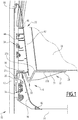
- a vehicle body 10 in particular a rail vehicle car body. More particularly, a side wall 12 of the box 10 is shown, as well as part of a floor 14 of the box 10.
- the wall 12 carries a device 16 for supporting a comfort element 18.
- the comfort element 18 is a seat, but it could alternatively also be chosen from a table and a luggage support.
- the support device 16 comprises a fixing rail 20, fixed to the side wall 12 and extending longitudinally along this side wall 12, that is to say parallel to a longitudinal direction of the car.
- the support device 16 also comprises at least one interface element 22, intended to be fixed to the comfort equipment 18 on the one hand, and to cooperate with the fixing rail 20 on the other hand, for fixing of this comfort equipment 18 on this fixing rail 20.
- the interface element 22 is for example made of aluminum or steel.
- the support device 16 comprises means (not shown) for fixing the interface element 22 on the fixing rail 20, without which the interface element 22 is movable in translation along the fixing rail 20, and with which the interface element 22 is locked in a selected position on the fixing rail 20.
- the fixing means comprise at least one orifice 24 (visible on the figure 2 ) formed on the interface element, and at least one complementary clamping screw passing through this orifice 24.
- the interface element 22 has an upper surface 22a and a lower surface 22b, and extends transversely (that is to say parallel to a transverse direction perpendicular to the longitudinal direction) between a first end 26 linked to the rail attachment 20 and a second end 28 attached to the comfort equipment 18.
- the interface element 22 comprises, between the first 26 and second 28 ends, a central portion 30 in which the upper surface 22a has a recess and the lower surface 22b has a boss.
- the central portion 30 has a V-shaped cross section.
- the interface element 22 comprises, on its lower surface 22b, stiffening ribs 31 extending transversely between the central portion 30 and the second end 28. It may also include, still on its lower surface 22b, stiffening ribs extending transversely between the central portion 30 and the first end 26.
- the interface element 22 also comprises stiffening ribs extending transversely in the hollow of the central portion 30.
- the comfort element 18 rests on the upper surface 22b, to which it is fixed by any suitable conceivable means.
- the support device 16 also comprises a set 32 of panels, in particular intended to conceal the fixing rail 20, and to conceal cables 34 running along the side wall 12, in particular electrical cables and network cables intended to be connected to equipment of the comfort element 18.
- equipment includes, for example, an electrical outlet, a lamp, a USB socket, and / or any conceivable equipment.
- the assembly 32 comprises a first lower panel 36 comprising a first upper end housed between the boss of the central portion 30 and the side wall 12, and a first lower end fixed to the ground.
- the support device 16 comprises at least one fixing element 38 fixed to the fixing rail 20 in the same way as the interface element 22. More particularly, each interface element 22 is interposed, in the longitudinal direction, between two fasteners 38, as shown in the figure 2 .
- the fixing element 38 is, in the same way as the interface element 22, mobile along the fixing rail 20 as long as it is not locked in a chosen position on this rail 20.
- the first upper end of the first lower panel 36 is fixed to the fixing element 38, for example by interlocking of complementary parts, and the first lower end of this first lower panel 36 is fixed to the ground 14 by at least one fixing member, for example by screwing.
- a masking strip 40 is attached to the first lower end, for example by snap-fastening, to mask the at least one fixing member.
- the assembly 32 also comprises a second intermediate panel 42 comprising a second upper end and a second lower end housed in the hollow of the central portion 30.
- the second lower end is also fixed to the fixing element 38, for example by interlocking of complementary parts.
- This second lower end covers the first upper end, with sufficient play between them to allow the passage of cables.
- the cables 34 can be connected to the comfort equipment by passing through this set, and along the interface element 22, to which they can advantageously be fixed.
- the clearance between the second lower end and the first upper end also allows the passage of the interface element 22.
- the second upper end is fixed to an intermediate fixing member 44, itself fixed to the wall 12.
- the assembly 32 finally comprises a third upper panel 46, comprising a third upper end and a third lower end.
- the third lower end covers the second upper end, and it is also fixed to the intermediate fixing member 44.
- the third upper end is fixed to an upper fixing member 48, for example by interlocking complementary parts, the upper fixing member 48 itself being fixed to the side wall 12.
- the intermediate 44 and upper 48 fastening members are for example fixed on rails carried by the side wall 12.
- the support device 16 includes an end piece at each longitudinal end of the assembly 32, intended to cover the longitudinal end edges of the panels.
- This end piece is for example made of aluminum.
- the panels 36, 42, 46 are for example also made of aluminum, and each have a thickness preferably less than 5 mm, for example 2.5 mm or 3 mm.
- the vehicle is a road vehicle such as a bus or a coach.
Abstract
Le dispositif de support (16) comporte un rail de fixation (20) fixé à une paroi latérale (12) et un élément d'interface (22), fixé à l'équipement de confort (18) et coopérant avec le rail de fixation (20). L'élément d'interface (22) présente des surfaces supérieure (22a) et inférieure (22b), et s'étend latéralement entre une première extrémité (26) liée au rail de fixation (20) et une seconde extrémité (28) fixée à l'équipement de confort (18). L'élément d'interface (22) comprend, entre ses extrémités, une portion centrale (30) dans laquelle la surface supérieure (22a) présente un creux et la surface inférieure (22b) présente une bosse. Le dispositif de support (16) comporte des panneaux (36, 42, 46) destinés à dissimuler le rail de fixation (20), notamment un premier panneau inférieur (36) comprenant une première extrémité haute logée entre la bosse de la portion centrale (30) et la première extrémité (26), et un second panneau (42) comprenant une seconde extrémité basse logée dans le creux de la portion centrale (30).The support device (16) comprises a fixing rail (20) fixed to a side wall (12) and an interface element (22), fixed to the comfort equipment (18) and cooperating with the fixing rail (20). The interface element (22) has upper (22a) and lower (22b) surfaces, and extends laterally between a first end (26) linked to the fixing rail (20) and a second end (28) fixed comfort equipment (18). The interface element (22) comprises, between its ends, a central portion (30) in which the upper surface (22a) has a recess and the lower surface (22b) has a boss. The support device (16) comprises panels (36, 42, 46) intended to conceal the fixing rail (20), in particular a first lower panel (36) comprising a first upper end housed between the boss of the central portion ( 30) and the first end (26), and a second panel (42) comprising a second low end housed in the hollow of the central portion (30).
Description
La présente invention concerne un support pour un élément de confort destiné à équiper un compartiment pour passagers.The present invention relates to a support for a comfort element intended to equip a passenger compartment.
Un tel compartiment comporte habituellement une pluralité d'éléments de confort, chaque élément de confort étant par exemple un siège, une table ou un support de bagages.Such a compartment usually comprises a plurality of comfort elements, each comfort element being for example a seat, a table or a luggage support.
Dans certains cas, il est souhaitable de pouvoir modifier les positions de ces éléments de confort, notamment pour adapter le compartiment à l'affluence et/ou aux besoins de passagers, par exemple en fonction du moment de la semaine ou de la saison. De telles modifications doivent être simples à réaliser, et cela de manière rapide et à bas coût.In certain cases, it is desirable to be able to modify the positions of these comfort elements, in particular to adapt the compartment to the influx and / or the needs of passengers, for example depending on the time of the week or the season. Such modifications must be simple to carry out, quickly and at low cost.
On connait déjà, dans l'état de la technique, un dispositif de support d'un élément de confort de voiture de véhicule, comportant :
- un rail de fixation destiné à être fixé à une paroi latérale de la voiture, de manière à s'étendre longitudinalement le long de cette paroi latérale,
- au moins un élément d'interface, destiné à être fixé à l'équipement de confort et à coopérer avec le rail de fixation, pour la solidarisation de cet équipement de confort avec ce rail de fixation.
- a fixing rail intended to be fixed to a side wall of the car, so as to extend longitudinally along this side wall,
- at least one interface element, intended to be fixed to the comfort equipment and to cooperate with the fixing rail, for the attachment of this comfort equipment with this fixing rail.
Le rail n'est généralement pas dissimulé, ou le dispositif comporte des panneaux de masquage du rail qui doivent être remplacés en cas de modification de la position des éléments de confort, ce qui implique des coûts supplémentaires.The rail is generally not concealed, or the device has rail masking panels which must be replaced in the event of a change in the position of the comfort elements, which involves additional costs.
L'invention a notamment pour but de remédier à cet inconvénient, en fournissant un dispositif de support dans lequel le rail de support est dissimulé, et cela sans nécessiter de remplacer les panneaux de masquage en cas de modification de la position des éléments de confort.The object of the invention is in particular to remedy this drawback, by providing a support device in which the support rail is concealed, and this without needing to replace the masking panels in the event of a change in the position of the comfort elements.
A cet effet, l'invention a notamment pour objet un dispositif de support d'un élément de confort de voiture de véhicule, comportant :
- un rail de fixation destiné à être fixé à une paroi latérale de la voiture, de manière à s'étendre longitudinalement le long de cette paroi latérale,
- au moins un élément d'interface, destiné à être fixé à l'équipement de confort et à coopérer avec le rail de fixation, pour la solidarisation de cet équipement de confort avec ce rail de fixation,
- l'élément d'interface présente une surface supérieure et une surface inférieure, et s'étend latéralement entre une première extrémité liée au rail de fixation et une seconde extrémité fixée à l'équipement de confort, l'élément d'interface comprenant, entre les première et seconde extrémités, une portion centrale dans laquelle la surface supérieure présente un creux et la surface inférieure présente une bosse,
- le dispositif de support comporte un ensemble de panneaux destiné à dissimuler le rail de fixation, l'ensemble comportant un premier panneau inférieur comprenant une première extrémité haute logée entre la bosse de la portion centrale et la première extrémité, et un second panneau comprenant une seconde extrémité basse logée dans le creux de la portion centrale.
- a fixing rail intended to be fixed to a side wall of the car, so as to extend longitudinally along this side wall,
- at least one interface element, intended to be fixed to the comfort equipment and to cooperate with the fixing rail, for the securing of this comfort equipment with this fixing rail,
- the interface element has an upper surface and a lower surface, and extends laterally between a first end linked to the fixing rail and a second end fixed to the comfort equipment, the interface element comprising, between the first and second ends, a central portion in which the upper surface has a hollow and the lower surface has a bump,
- the support device comprises a set of panels intended to conceal the fixing rail, the assembly comprising a first lower panel comprising a first upper end housed between the boss of the central portion and the first end, and a second panel comprising a second lower end housed in the hollow of the central portion.
Un dispositif de support selon l'invention peut comporter en outre l'une ou plusieurs des caractéristiques suivantes.
- Le dispositif de support comporte des moyens de fixation de l'élément d'interface sur le rail de fixation, sans lesquels l'élément d'interface est mobile en translation le long du rail de fixation, et avec lesquels l'élément d'interface est verrouillé dans une position choisie sur le rail de fixation.
- Les moyens de fixation comportent au moins un orifice ménagé sur l'élément d'interface, et au moins une vis de serrage complémentaire passant à travers cet orifice pour coopérer avec le rail de fixation.
- Le premier panneau inférieur comporte une première extrémité basse destinée à être fixée à un sol de la caisse, par au moins un organe de fixation, et comprenant une bande de masquage de l'au moins un organe de fixation, rapportée sur le premier panneau inférieur, par exemple par encliquetage.
- L'ensemble comporte, en plus du premier panneau inférieur et du second panneau, un troisième panneau supérieur agencé au-dessus du second panneau.
- Lequel l'élément d'interface comprend des nervures de rigidification, choisies parmi : des nervures de rigidification sur sa surface inférieure, s'étendant transversalement entre la portion centrale et la seconde extrémité, des nervures de rigidification sur sa surface inférieure, s'étendant transversalement entre la portion centrale et la première extrémité, et/ou des nervures de rigidification s'étendant transversalement dans le creux de la portion centrale.
- Le dispositif de support comporte au moins un élément de fixation fixé au rail de fixation, la première extrémité haute du premier panneau inférieur étant fixée à l'élément de fixation, par exemple par emboîtement de parties complémentaires, et la seconde extrémité basse du second panneau est également fixée à l'élément de fixation, par exemple par emboîtement de parties complémentaires.
- La seconde extrémité basse recouvre la première extrémité haute, avec entre elles un jeu suffisant pour permettre le passage de câbles.
- The support device comprises means for fixing the interface element to the fixing rail, without which the interface element is movable in translation along the fixing rail, and with which the interface element is locked in a selected position on the fixing rail.
- The fixing means comprise at least one orifice made on the interface element, and at least one complementary clamping screw passing through this orifice to cooperate with the fixing rail.
- The first lower panel has a first lower end intended to be fixed to a floor of the body, by at least one fixing member, and comprising a masking strip of the at least one fixing member, attached to the first lower panel. , for example by snap-fastening.
- The assembly comprises, in addition to the first lower panel and the second panel, a third upper panel arranged above the second panel.
- Which the interface element comprises stiffening ribs, chosen from: stiffening ribs on its lower surface, extending transversely between the central portion and the second end, stiffening ribs on its lower surface, extending transversely between the central portion and the first end, and / or stiffening ribs extending transversely in the hollow of the central portion.
- The support device comprises at least one fixing element fixed to the fixing rail, the first upper end of the first lower panel being fixed to the fixing element, for example by interlocking of complementary parts, and the second lower end of the second panel is also fixed to the fixing element, for example by interlocking of complementary parts.
- The second lower end covers the first upper end, with sufficient clearance between them to allow the passage of cables.
L'invention concerne également une paroi latérale de caisse de véhicule, caractérisée en ce qu'elle comporte un dispositif de support tel que défini précédemment.The invention also relates to a side wall of the vehicle body, characterized in that it comprises a support device as defined above.
L'invention sera mieux comprise à la lecture de la description qui va suivre, donnée uniquement à titre d'exemple et faite en se référant aux figures annexées parmi lesquelles :
- [
Fig 1 ] Lafigure 1 est une vue en coupe d'une paroi latérale d'une caisse de voiture de véhicule selon un exemple de mode de réalisation de l'invention ; - [
Fig 2 ] Lafigure 2 est une vue en perspective de l'arrière d'un ensemble de panneaux de dissimulation équipant la paroi latérale de lafigure 1 .
- [
Fig 1 ] Thefigure 1 is a sectional view of a side wall of a vehicle car body according to an exemplary embodiment of the invention; - [
Fig 2 ] Thefigure 2 is a perspective view of the rear of a set of concealment panels fitted to the side wall of thefigure 1 .
On a représenté partiellement, sur la
La paroi 12 porte un dispositif 16 de support d'un élément de confort 18. Par exemple, l'élément de confort 18 est un siège, mais il pourrait en variante être également choisi parmi une table et un support de bagages.The
Le dispositif de support 16 comporte un rail de fixation 20, fixé à la paroi latérale 12 et s'étendant longitudinalement le long de cette paroi latérale 12, c'est-à-dire parallèlement à une direction longitudinale de la voiture.The
Le dispositif de support 16 comporte par ailleurs au moins un élément d'interface 22, destiné à être fixé à l'équipement de confort 18 d'une part, et à coopérer avec le rail de fixation 20 d'autre part, pour la fixation de cet équipement de confort 18 sur ce rail de fixation 20.The
L'élément d'interface 22 est par exemple réalisé en aluminium ou en acier.The
Le dispositif de support 16 comporte des moyens (non représentés) de fixation de l'élément d'interface 22 sur le rail de fixation 20, sans lesquels l'élément d'interface 22 est mobile en translation le long du rail de fixation 20, et avec lesquels l'élément d'interface 22 est verrouillé dans une position choisie sur le rail de fixation 20.The
Par exemple les moyens de fixation comportent au moins un orifice 24 (visible sur la
L'élément d'interface 22 présente une surface supérieure 22a et une surface inférieure 22b, et s'étend transversalement (c'est-à-dire parallèlement à une direction transversale perpendiculaire à la direction longitudinale) entre une première extrémité 26 liée au rail de fixation 20 et une seconde extrémité 28 fixée à l'équipement de confort 18.The
L'élément d'interface 22 comprend, entre les première 26 et seconde 28 extrémités, une portion centrale 30 dans laquelle la surface supérieure 22a présente un creux et la surface inférieure 22b présente une bosse. Par exemple, la portion centrale 30 présente une section transversale en forme de V.The
Avantageusement, l'élément d'interface 22 comprend, sur sa surface inférieure 22b, des nervures de rigidification 31 s'étendant transversalement entre la portion centrale 30 et la seconde extrémité 28. Il peut également comporter, toujours sur sa surface inférieure 22b, des nervures de rigidification s'étendant transversalement entre la portion centrale 30 et la première extrémité 26.Advantageously, the
Avantageusement, l'élément d'interface 22 comprend également des nervures de rigidification s'étendant transversalement dans le creux de la portion centrale 30.Advantageously, the
L'élément de confort 18 repose sur la surface supérieure 22b, à laquelle il est fixé par tout moyen approprié envisageable.The
Le dispositif de support 16 comporte par ailleurs un ensemble 32 de panneaux, notamment destiné à dissimuler le rail de fixation 20, et à dissimuler des câbles 34 courant le long de la paroi latérale 12, notamment des câbles électriques et des câbles réseau destinés à être connectés à des équipements de l'élément de confort 18. De tels équipements comportent par exemple une prise électrique, une lampe, une prise USB, et/ou tout équipement envisageable.The
L'ensemble 32 comporte un premier panneau inférieur 36 comprenant une première extrémité haute logée entre la bosse de la portion centrale 30 et la paroi latérale 12, et une première extrémité basse fixée au sol.The
Le dispositif de support 16 comporte au moins un élément de fixation 38 fixé au rail de fixation 20 de la même façon que l'élément d'interface 22. Plus particulièrement, chaque élément d'interface 22 est intercalé, dans la direction longitudinale, entre deux éléments de fixation 38, comme cela est représenté sur la
L'élément de fixation 38 est, de la même manière que l'élément d'interface 22, mobile le long du rail de fixation 20 tant qu'il n'est pas verrouillé dans une position choisie sur ce rail 20.The fixing
La première extrémité haute du premier panneau inférieur 36 est fixée à l'élément de fixation 38, par exemple par emboîtement de parties complémentaires, et la première extrémité basse de ce premier panneau inférieur 36 est fixée au sol 14 par au moins un organe de fixation, par exemple par vissage. Avantageusement, une bande de masquage 40 est rapportée sur la première extrémité basse, par exemple par encliquetage, pour masquer l'au moins un organe de fixation.The first upper end of the first
L'ensemble 32 comporte par ailleurs un second panneau intermédiaire 42 comprenant une seconde extrémité haute et une seconde extrémité basse logée dans le creux de la portion centrale 30.The
La seconde extrémité basse est également fixée à l'élément de fixation 38, par exemple par emboîtement de parties complémentaires. Cette seconde extrémité basse recouvre la première extrémité haute, avec entre elles un jeu suffisant pour permettre le passage de câbles. Ainsi, les câbles 34 peuvent être reliés à l'équipement de confort en passant à travers ce jeu, et en longeant l'élément d'interface 22, auquel ils peuvent avantageusement être fixés.The second lower end is also fixed to the fixing
Le jeu entre la seconde extrémité basse et la première extrémité haute permet également le passage de l'élément d'interface 22.The clearance between the second lower end and the first upper end also allows the passage of the
La seconde extrémité haute est fixée à un organe de fixation intermédiaire 44, lui-même fixé à la paroi 12.The second upper end is fixed to an
L'ensemble 32 comporte enfin un troisième panneau supérieur 46, comprenant une troisième extrémité haute et une troisième extrémité basse.The
La troisième extrémité basse recouvre la seconde extrémité haute, et elle est également fixée à l'organe de fixation intermédiaire 44.The third lower end covers the second upper end, and it is also fixed to the intermediate fixing
La troisième extrémité haute est fixée à un organe de fixation supérieure 48, par exemple par emboîtement de parties complémentaires, l'organe de fixation supérieure 48 étant lui-même fixé à la paroi latérale 12.The third upper end is fixed to an upper fixing
Les organes de fixation intermédiaire 44 et supérieure 48 sont par exemple fixés sur des rails portés par la paroi latérale 12.The intermediate 44 and upper 48 fastening members are for example fixed on rails carried by the
De manière optionnelle, le dispositif de support 16 comporte une pièce d'extrémité à chaque extrémité longitudinale de l'ensemble 32, destinée à recouvrir les bords d'extrémité longitudinale des panneaux. Cette pièce d'extrémité est par exemple réalisée en aluminium.Optionally, the
Les panneaux 36, 42, 46 sont par exemple également réalisés en aluminium, et présentent chacun une épaisseur de préférence inférieure à 5 mm, par exemple de 2,5 mm ou 3 mm.The
En variante le véhicule est véhicule routier tel qu'un bus ou un car.As a variant, the vehicle is a road vehicle such as a bus or a coach.
Claims (10)
Applications Claiming Priority (1)
| Application Number | Priority Date | Filing Date | Title |
|---|---|---|---|
| FR1871693A FR3088866B1 (en) | 2018-11-22 | 2018-11-22 | Device for supporting a vehicle car comfort element |
Publications (1)
| Publication Number | Publication Date |
|---|---|
| EP3656607A1 true EP3656607A1 (en) | 2020-05-27 |
Family
ID=65763636
Family Applications (1)
| Application Number | Title | Priority Date | Filing Date |
|---|---|---|---|
| EP19210791.0A Pending EP3656607A1 (en) | 2018-11-22 | 2019-11-21 | Device for supporting a comfort element in a vehicle |
Country Status (2)
| Country | Link |
|---|---|
| EP (1) | EP3656607A1 (en) |
| FR (1) | FR3088866B1 (en) |
Cited By (1)
| Publication number | Priority date | Publication date | Assignee | Title |
|---|---|---|---|---|
| EP4275963A1 (en) * | 2022-05-09 | 2023-11-15 | Ambulanz Mobile GmbH & Co. KG | Motor vehicle side wall structure, side wall elements for a motor vehicle side wall structure and method of assembly |
Citations (3)
| Publication number | Priority date | Publication date | Assignee | Title |
|---|---|---|---|---|
| EP0754621A1 (en) * | 1995-07-20 | 1997-01-22 | DaimlerChrysler Aerospace Airbus Gesellschaft mit beschränkter Haftung | Device to divide an aircraft cabin |
| EP2033869A1 (en) * | 2007-09-06 | 2009-03-11 | Alstom Transport S.A. | Vehicle comprising a multifunctional equipment support structure |
| FR2979316A1 (en) * | 2011-08-31 | 2013-03-01 | M Y G | Prefabricated interior trim module for cockpit of e.g. airplane, has wall comprising guidance path along which accessory is rectilinearly guided, where accessory is mounted to slide in uncoupled state of accessory with floor of cockpit |
-
2018
- 2018-11-22 FR FR1871693A patent/FR3088866B1/en active Active
-
2019
- 2019-11-21 EP EP19210791.0A patent/EP3656607A1/en active Pending
Patent Citations (3)
| Publication number | Priority date | Publication date | Assignee | Title |
|---|---|---|---|---|
| EP0754621A1 (en) * | 1995-07-20 | 1997-01-22 | DaimlerChrysler Aerospace Airbus Gesellschaft mit beschränkter Haftung | Device to divide an aircraft cabin |
| EP2033869A1 (en) * | 2007-09-06 | 2009-03-11 | Alstom Transport S.A. | Vehicle comprising a multifunctional equipment support structure |
| FR2979316A1 (en) * | 2011-08-31 | 2013-03-01 | M Y G | Prefabricated interior trim module for cockpit of e.g. airplane, has wall comprising guidance path along which accessory is rectilinearly guided, where accessory is mounted to slide in uncoupled state of accessory with floor of cockpit |
Cited By (1)
| Publication number | Priority date | Publication date | Assignee | Title |
|---|---|---|---|---|
| EP4275963A1 (en) * | 2022-05-09 | 2023-11-15 | Ambulanz Mobile GmbH & Co. KG | Motor vehicle side wall structure, side wall elements for a motor vehicle side wall structure and method of assembly |
Also Published As
| Publication number | Publication date |
|---|---|
| FR3088866A1 (en) | 2020-05-29 |
| FR3088866B1 (en) | 2021-06-25 |
Similar Documents
| Publication | Publication Date | Title |
|---|---|---|
| FR2902052A1 (en) | DEPLIABLE SEAT FOR TRANSPORT VEHICLE AND TRANSPORT VEHICLE THEREFOR | |
| FR2787402A1 (en) | ROOF GALLERY FOR VEHICLES | |
| EP3656607A1 (en) | Device for supporting a comfort element in a vehicle | |
| EP3356168B1 (en) | Flush-fitted glazed device for a vehicle door comprising a movable panel, and corresponding door and motor vehicle | |
| EP3865366A1 (en) | Car of a public transport vehicle, in particular of a rail vehicle, and associated fitting-out method | |
| FR3055874A1 (en) | MODULAR RESTORATION CAR, IN PARTICULAR FOR A RAILWAY VEHICLE | |
| FR3000007A3 (en) | Cross-piece for instrument panel in driver's cab of vehicle, has fixing units provided at top and bottom of vertical legs for fixing vertical legs at main transverse metal element and at floor of vehicle | |
| FR2996182A1 (en) | SLIDER AND SEAT FOR A MOTOR VEHICLE COMPRISING SUCH A SLIDER | |
| EP3996954B1 (en) | Device for fastening a motor vehicle door frame lateral edge trim piece | |
| FR3041309A1 (en) | SEAT STRUCTURE FOR A PUBLIC TRANSPORT VEHICLE, IN PARTICULAR A RAILWAY VEHICLE | |
| EP3828026A1 (en) | Device for attaching a vehicle seat | |
| EP1884454A1 (en) | Device for installing a signalling light and a bumper skin on a rear structure of a vehicle and vehicle comprising at least one such device. | |
| FR2883225A1 (en) | Panoramic glazing frame for vehicle, is based on single-piece, triangular hollow tubular component forming column, used with adhesive and clip-in sealing strip | |
| EP3925849B1 (en) | Car of a vehicle, in particular a railway vehicle, comprising a skylight and associated assembly method | |
| FR2878587A1 (en) | Roof cover fastening clip for motor vehicle, has attachments with terminals turned towards direction opposite to another direction along which lugs are directed inside clip, and other lugs extending, towards outside clip, from attachments | |
| FR3062367B1 (en) | DASHBOARD TRAVERSE AND MODULAR STEERING COLUMN SUPPORT CONSOLE | |
| WO2023233087A1 (en) | Support for an electronics housing of a motor vehicle | |
| FR3103453A1 (en) | MOUNTING OF TRIMS ON A MOTOR VEHICLE SPRING | |
| FR2779581A1 (en) | ENCLOSURE FOR HOUSING ELECTRICAL EQUIPMENT | |
| EP3254903B1 (en) | Part for attaching trim elements to a side structure element of a motor vehicle | |
| EP3408177B1 (en) | Stop for aircraft seat | |
| FR3092804A1 (en) | MOUNTING FOR MOTOR VEHICLE TRIMS | |
| EP4091873A1 (en) | Seat for passenger transport vehicle and passenger transport vehicle comprising such a seat | |
| FR3085337A1 (en) | RAIL VEHICLE CAB AND ASSEMBLY METHOD | |
| FR2630477A1 (en) | SUSPENDED CEILING LAYOUT |
Legal Events
| Date | Code | Title | Description |
|---|---|---|---|
| PUAI | Public reference made under article 153(3) epc to a published international application that has entered the european phase |
Free format text: ORIGINAL CODE: 0009012 |
|
| STAA | Information on the status of an ep patent application or granted ep patent |
Free format text: STATUS: THE APPLICATION HAS BEEN PUBLISHED |
|
| STAA | Information on the status of an ep patent application or granted ep patent |
Free format text: STATUS: REQUEST FOR EXAMINATION WAS MADE |
|
| AK | Designated contracting states |
Kind code of ref document: A1 Designated state(s): AL AT BE BG CH CY CZ DE DK EE ES FI FR GB GR HR HU IE IS IT LI LT LU LV MC MK MT NL NO PL PT RO RS SE SI SK SM TR |
|
| AX | Request for extension of the european patent |
Extension state: BA ME |
|
| 17P | Request for examination filed |
Effective date: 20200519 |
|
| RBV | Designated contracting states (corrected) |
Designated state(s): AL AT BE BG CH CY CZ DE DK EE ES FI FR GB GR HR HU IE IS IT LI LT LU LV MC MK MT NL NO PL PT RO RS SE SI SK SM TR |
|
| STAA | Information on the status of an ep patent application or granted ep patent |
Free format text: STATUS: EXAMINATION IS IN PROGRESS |
|
| 17Q | First examination report despatched |
Effective date: 20210920 |
|
| P01 | Opt-out of the competence of the unified patent court (upc) registered |
Effective date: 20231026 |