EP3656583A1 - Pneumatique - Google Patents
Pneumatique Download PDFInfo
- Publication number
- EP3656583A1 EP3656583A1 EP19209698.0A EP19209698A EP3656583A1 EP 3656583 A1 EP3656583 A1 EP 3656583A1 EP 19209698 A EP19209698 A EP 19209698A EP 3656583 A1 EP3656583 A1 EP 3656583A1
- Authority
- EP
- European Patent Office
- Prior art keywords
- tire
- sound absorption
- absorption layer
- exposed portion
- layer
- Prior art date
- Legal status (The legal status is an assumption and is not a legal conclusion. Google has not performed a legal analysis and makes no representation as to the accuracy of the status listed.)
- Granted
Links
- 238000010521 absorption reaction Methods 0.000 claims abstract description 74
- 239000000565 sealant Substances 0.000 claims abstract description 51
- 239000000463 material Substances 0.000 claims abstract description 36
- 230000002265 prevention Effects 0.000 claims abstract description 33
- 239000012812 sealant material Substances 0.000 description 11
- 229920005549 butyl rubber Polymers 0.000 description 8
- 238000000034 method Methods 0.000 description 8
- 229920001971 elastomer Polymers 0.000 description 7
- 239000005060 rubber Substances 0.000 description 7
- 230000000694 effects Effects 0.000 description 6
- 229920002635 polyurethane Polymers 0.000 description 5
- 239000004814 polyurethane Substances 0.000 description 5
- RTZKZFJDLAIYFH-UHFFFAOYSA-N Diethyl ether Chemical compound CCOCC RTZKZFJDLAIYFH-UHFFFAOYSA-N 0.000 description 4
- 239000004698 Polyethylene Substances 0.000 description 4
- -1 polyethylene Polymers 0.000 description 4
- 229920000573 polyethylene Polymers 0.000 description 4
- 229920001296 polysiloxane Polymers 0.000 description 3
- 239000002994 raw material Substances 0.000 description 3
- 230000001629 suppression Effects 0.000 description 3
- 229920000459 Nitrile rubber Polymers 0.000 description 2
- 239000004721 Polyphenylene oxide Substances 0.000 description 2
- 125000000484 butyl group Chemical group [H]C([*])([H])C([H])([H])C([H])([H])C([H])([H])[H] 0.000 description 2
- 230000000052 comparative effect Effects 0.000 description 2
- 239000007788 liquid Substances 0.000 description 2
- 239000000203 mixture Substances 0.000 description 2
- 239000004745 nonwoven fabric Substances 0.000 description 2
- 229920001083 polybutene Polymers 0.000 description 2
- 229920000570 polyether Polymers 0.000 description 2
- 229920005862 polyol Polymers 0.000 description 2
- 150000003077 polyols Chemical class 0.000 description 2
- 239000007921 spray Substances 0.000 description 2
- 239000000126 substance Substances 0.000 description 2
- 238000012360 testing method Methods 0.000 description 2
- 229920002943 EPDM rubber Polymers 0.000 description 1
- 229920000181 Ethylene propylene rubber Polymers 0.000 description 1
- 239000004793 Polystyrene Substances 0.000 description 1
- 239000012190 activator Substances 0.000 description 1
- 239000006229 carbon black Substances 0.000 description 1
- KMGMCLWJFCGWFI-UHFFFAOYSA-N chembl3276923 Chemical compound ON=C1C=CC(=O)C=C1 KMGMCLWJFCGWFI-UHFFFAOYSA-N 0.000 description 1
- 238000004132 cross linking Methods 0.000 description 1
- 239000003431 cross linking reagent Substances 0.000 description 1
- 238000013461 design Methods 0.000 description 1
- 150000002148 esters Chemical class 0.000 description 1
- 230000001747 exhibiting effect Effects 0.000 description 1
- 230000002349 favourable effect Effects 0.000 description 1
- 239000012634 fragment Substances 0.000 description 1
- 230000005484 gravity Effects 0.000 description 1
- 238000005470 impregnation Methods 0.000 description 1
- 230000002401 inhibitory effect Effects 0.000 description 1
- 238000002156 mixing Methods 0.000 description 1
- 238000012986 modification Methods 0.000 description 1
- 230000004048 modification Effects 0.000 description 1
- 229920001084 poly(chloroprene) Polymers 0.000 description 1
- 229920000728 polyester Polymers 0.000 description 1
- 229920005906 polyester polyol Polymers 0.000 description 1
- 229920002223 polystyrene Polymers 0.000 description 1
- 239000011148 porous material Substances 0.000 description 1
- 238000007789 sealing Methods 0.000 description 1
- 229920003002 synthetic resin Polymers 0.000 description 1
- 239000000057 synthetic resin Substances 0.000 description 1
- 239000000454 talc Substances 0.000 description 1
- 229910052623 talc Inorganic materials 0.000 description 1
- 238000010998 test method Methods 0.000 description 1
- 238000013519 translation Methods 0.000 description 1
- 230000000007 visual effect Effects 0.000 description 1
- XLYOFNOQVPJJNP-UHFFFAOYSA-N water Substances O XLYOFNOQVPJJNP-UHFFFAOYSA-N 0.000 description 1
Images


Classifications
-
- B—PERFORMING OPERATIONS; TRANSPORTING
- B60—VEHICLES IN GENERAL
- B60C—VEHICLE TYRES; TYRE INFLATION; TYRE CHANGING; CONNECTING VALVES TO INFLATABLE ELASTIC BODIES IN GENERAL; DEVICES OR ARRANGEMENTS RELATED TO TYRES
- B60C19/00—Tyre parts or constructions not otherwise provided for
- B60C19/002—Noise damping elements provided in the tyre structure or attached thereto, e.g. in the tyre interior
-
- B—PERFORMING OPERATIONS; TRANSPORTING
- B60—VEHICLES IN GENERAL
- B60C—VEHICLE TYRES; TYRE INFLATION; TYRE CHANGING; CONNECTING VALVES TO INFLATABLE ELASTIC BODIES IN GENERAL; DEVICES OR ARRANGEMENTS RELATED TO TYRES
- B60C19/00—Tyre parts or constructions not otherwise provided for
- B60C19/12—Puncture preventing arrangements
- B60C19/122—Puncture preventing arrangements disposed inside of the inner liner
Definitions
- the present invention relates to a pneumatic tire having a tread portion on which a sealant layer and a sound absorption layer are disposed.
- Japanese Laid-Open Patent Publication (translation of PCT application) No. 2018-520928 discloses a pneumatic tire including, on the inner surface of a tread thereof, a sealant layer and a sound absorption member attached to the inner side in a tire radial direction of the sealant layer.
- the sealant layer serves to close a puncture hole in the tread.
- the sound absorption member allows reduction in road noise.
- the above-described pneumatic tire has the following problem.
- a foreign object pierces the tread and penetrates the sound absorption member, the sound absorption member is sometimes partially fractured.
- fragments (fracture pieces) of the fractured sound absorption member enter and remain in, together with a sealant material, the hole opened by the foreign object, and thus tend to reduce the puncture hole-closing effect of the sealant layer.
- about 30 to 40% of the internal pressure of the tire is lost, and sufficient air-seal performance is not obtained.
- the inventor attempted to sufficiently increase the thickness of a sound absorption member.
- the reason for this attempt is because increase in the thickness of the sound absorption member makes it less likely for foreign objects to penetrate the sound absorption member, resulting in suppression of partial fracture of the sound absorption member.
- the sound absorption member having a large thickness had the following tendencies: when a tread portion and/or the sound absorption member is deformed during running with the tire, side surfaces of the sound absorption member easily come into contact with a sealant layer, and from then on, is left adhering to the sealant layer. If such adhesion occurs, the thickness of the sound absorption member is reduced again (the sound absorption member is made flat). Therefore, the problem of inability to obtain sufficient air-seal performance still persisted.
- the present invention has been made in view of the above-described circumstances, and a main object of the present invention is to provide a pneumatic tire capable of exhibiting sufficient air-seal performance while maintaining road noise performance.
- the present invention is a pneumatic tire having a tread portion.
- a sealant layer extending in a tire axial direction from a first end to a second end thereof, and a sound absorption layer adhered to an inner side in a tire radial direction of the sealant layer and formed of a sponge material, are disposed at a side where a tire inner cavity is present.
- the sealant layer is, at least at the first end side, uncovered with the sound absorption layer but provided with a first exposed portion exposed to the tire inner cavity and extending in the tire axial direction.
- the sound absorption layer has, at a side where the first exposed portion is present, a first side surface which extends in the tire radial direction and at which the sound absorption layer has a thickness not less than 25 mm.
- the first side surface is provided with an adhesion prevention portion by which the first side surface and the first exposed portion are prevented from adhering to each other when coming into contact with each other owing to deformation of the sound absorption layer or the tread portion.
- the present invention is a pneumatic tire having a tread portion.
- a sealant layer extending in a tire axial direction from a first end to a second end thereof, and a sound absorption layer adhered to an inner side in a tire radial direction of the sealant layer and formed of a sponge material, are disposed at a side where a tire inner cavity is present.
- the sealant layer is, at least at the first end side, uncovered with the sound absorption layer but provided with a first exposed portion exposed to the tire inner cavity and extending in the tire axial direction.
- the sound absorption layer has, at a side where the first exposed portion is present, a first side surface which extends in the tire radial direction and at which the sound absorption layer has a thickness not less than 25 mm.
- the first exposed portion is provided with an adhesion prevention portion by which the first side surface and the first exposed portion are prevented from adhering to each other when coming into contact with each other owing to deformation of the sound absorption layer or the tread portion.
- the adhesion prevention portion is preferably disposed over a range from an inner end in the tire radial direction of the first side surface to a position corresponding to not less than 20% of the thickness at the first side surface.
- the adhesion prevention portion is preferably disposed over a region within which a portion, of the first side surface, that extends over a range from an inner end in the tire radial direction of the first side surface to a position corresponding to not less than 20% of the thickness at the first side surface, comes into contact with the first exposed portion at the time of deformation owing to which the first side surface rotates to the first end side about an outer end in the tire radial direction of the first side surface and comes into contact with the first exposed portion.
- the adhesion prevention portion preferably includes a layer formed of a mold-release material.
- the adhesion prevention portion preferably includes a recessed and projecting portion which allows reduction in an area of contact between the first side surface and the first exposed portion.
- the first exposed portion is preferably provided with an adhesion prevention portion by which the first side surface and the first exposed portion are prevented from adhering to each other when coming into contact with each other owing to deformation of the sound absorption layer or the tread portion.
- the thickness at the first side surface is preferably not less than 30 mm, and a width in the tire axial direction of the first exposed portion is preferably not greater than 15 mm.
- the first side surface of the sound absorption layer or the first exposed portion of the sealant layer includes the adhesion prevention portion by which the first side surface and the first exposed portion are prevented from adhering to each other when coming into contact with each other owing to deformation of the sound absorption layer or the tread portion.
- the sound absorption layer is maintained to have a sufficient thickness, and thus foreign objects are less likely to penetrate the sound absorption layer, resulting in suppression of generation of fracture pieces and the like due to fracture of the sound absorption layer. Accordingly, the pneumatic tire according to the present invention suppresses entry of fracture pieces of the sound absorption layer into a hole that is to be sealed, and thus exhibits sufficient air-seal performance.
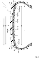
- FIG. 1 is a tire meridian cross-sectional view of a pneumatic tire (hereinafter, sometimes referred to simply as "tire") 1 according to the embodiment of the present invention in a normal state.
- a pneumatic tire 1 for passenger cars is described as a preferable mode.
- the present invention may be implemented by, for example, a pneumatic tire 1 for two-wheeled automotive vehicles or a heavy-duty pneumatic tire 1.
- the "normal state” refers to a state where the tire 1 is mounted to a normal rim (not shown) and inflated to a normal internal pressure, and no load is applied to the tire 1.
- the dimension and the like of each portion of the tire 1 are values measured in the normal state.
- the "normal rim” refers to a rim that is defined, in a standard system including a standard on which the tire 1 is based, by the standard for each tire, and is, for example, the "Standard Rim” in the JATMA standard, the “Design Rim” in the TRA standard, or the “Measuring Rim” in the ETRTO standard.
- the "normal internal pressure” refers to an air pressure that is defined, in a standard system including a standard on which the tire 1 is based, by the standard for each tire, and is the “maximum air pressure” in the JATMA standard, the maximum value indicated in the table “TIRE LOAD LIMITS AT VARIOUS COLD INFLATION PRESSURES" in the TRA standard, and the "INFLATION PRESSURE” in the ETRTO standard.
- the tire 1 according to the present embodiment has therein tire components such as a carcass 6, a belt layer 7, and an inner liner 9 formed of an air-impermeable rubber material.
- tire components such as a carcass 6, a belt layer 7, and an inner liner 9 formed of an air-impermeable rubber material.
- Known types of components are used, as appropriate, as these tire components.
- a sealant layer 10 and a sound absorption layer 11 which is formed of a sponge material 11a, are disposed, on a tread portion 2, at a side where a tire inner cavity i is present.
- the sealant layer 10 in the present embodiment is adhered to a surface 9a, of the inner liner 9, that faces inward in the tire radial direction.
- the sound absorption layer 11 in the present embodiment is adhered to the inner side in the tire radial direction of the sealant layer 10.
- the sealant layer 10 is formed of a sealant material 10A having such a viscosity as to fill a hole that is to be formed owing to puncture.
- a puncture hole is formed in the tread portion 2 by, for example, the tire treading over a nail during running, such a sealant layer 10 is deformed so as to close the hole, thereby inhibiting air leakage.
- the sealant layer 10 in the present embodiment has a first end 10e (right side in FIG. 1 ) and a second end 10i (left side in FIG. 1 ) in the tire axial direction, and extends from the first end 10e to the second end 10i.
- the sealant layer 10 in the present embodiment continuously extends for one turn in the tire circumferential direction.
- the sealant layer 10 is, at the first end 10e side, uncovered with the sound absorption layer 11 but provided with a first exposed portion 13A exposed to the tire inner cavity i and extending in the tire axial direction.
- the sealant layer 10 in the present embodiment is, also at the second end 10i side, uncovered with the sound absorption layer 11 but provided with a second exposed portion 13B exposed to the tire inner cavity i and extending in the tire axial direction.
- the sealant layer 10 further has a covered portion 14 covered with the sound absorption layer 11.
- the covered portion 14 in the present embodiment is disposed between the first exposed portion 13A and the second exposed portion 13B.
- the covered portion 14 continuously extends in the tire axial direction between the first exposed portion 13A and the second exposed portion 13B, for example.
- the first exposed portion 13A, the second exposed portion 13B, and the covered portion 14 in the present embodiment are formed on an inner surface 10a, of the sealant layer 10, that faces inward in the tire radial direction.
- the width Wa in the tire axial direction of the sealant layer 10 is preferably 80% to 120% of a tread width TW. If the width Wa is within the range, puncture holes can be effectively closed over a wide range of the tread portion 2.
- the "tread width TW” refers to a length in the tire axial direction between tread ends Te and Te which are ground-contact positions on both outermost sides in the tire axial direction in a state where a normal load is applied to the tire 1 in the normal state and the tire 1 is brought into contact with a flat surface at a camber angle of 0°
- the "normal load” refers to a load that is defined, in a standard system including a standard on which the tire is based, by the standard for each tire, and is the “maximum load capacity" in the JATMA standard, the maximum value indicated in the table "TIRE LOAD LIMITS AT VARIOUS COLD INFLATION PRESSURES" in the TRA standard, or the "LOAD CAPACITY" in the ETRTO standard.
- the sound absorption layer 11 in the present embodiment has an outward facing surface 15 which faces the sealant layer 10 side, an inward facing surface 16 which is disposed on the side opposite to the outward facing surface 15 and faces inward in the tire radial direction, and a pair of side surfaces 17 which connect the outward facing surface 15 and the inward facing surface 16. That is, the sound absorption layer 11 has a substantially rectangular shape in a tire-meridian cross-sectional view.
- the outward facing surface 15 in the present embodiment is in contact with the sealant layer 10.
- the inward facing surface 16 in the present embodiment is exposed to the tire inner cavity i.
- the pair of side surfaces 17 include, for example, a first side surface 17e on the first end 10e side and a second side surface 17i on the second end 10i side.
- Both the sealant layer 10 and the sound absorption layer 11 in the present embodiment are formed so as to be identical between the first end 10e side and the second end 10i side. Therefore, in the present specification, explanations made on the first end 10e side apply also to the second end 10i side. That is, elements formed on the first side surface 17e can be formed also on the second side surface 17i. Similarly, elements formed on the first exposed portion 13A can be formed also on the second exposed portion 13B. The only explanations made on the second end 10i side are differences from the first end 10e side.
- FIG. 2 is an enlarged view of the first end 10e side of the sealant layer 10 in FIG. 1 .
- the first side surface 17e at which the sound absorption layer 11 has a thickness ta that is, for example, not less than 25 mm extends in the tire radial direction.
- the sound absorption layer 11 in the present embodiment is formed in a substantially rectangular shape, the sound absorption layer 11 is preferably formed so as to have a thickness t1 not less than 25 mm over the entirety thereof extending in the tire axial direction.
- the first side surface 17e includes an adhesion prevention portion 19 by which the first side surface 17e and the first exposed portion 13A are prevented from adhering to each other when coming into contact with each other owing to deformation of the sound absorption layer 11 or the tread portion 2.
- Such a tire 1 has the following advantageous effects. Even when various impacts or forces are exerted to the tread portion 2 during running with the tire, adhesion between the first side surface 17e of the sound absorption layer 11 and the sealant layer 10 is suppressed.
- the sound absorption layer 11 is inhibited from being made further flat and is maintained to have a sufficient thickness t1, and thus foreign objects are less likely to penetrate the sound absorption layer 11 to cause puncture, resulting in suppression of generation of fracture pieces (not shown) and the like due to fracture of the sound absorption layer 11. Accordingly, the tire 1 suppresses entry of fracture pieces of the sponge material 11a into a puncture hole that is to be sealed, and thus exhibits sufficient air-seal performance.
- the thickness t1 of the sound absorption layer 11 is sufficiently ensured as described above, the sponge material 11a does not become excessively thin, whereby a sound absorption effect is ensured, and thus the road noise performance is maintained at a high level.
- the thickness ta at the first side surface 17e is preferably not less than 30 mm in order for the above-described advantageous effects to be effectively exhibited. However, if the thickness ta is greater than 40 mm, although the effect of making foreign objects less likely to penetrate the sound absorption layer 11 reaches the highest level, the sound absorption layer 11 comes to have a lower rigidity, and thus may become easily fractured. Therefore, the thickness ta at the first side surface 17e is preferably not greater than 40 mm.
- the adhesion prevention portion 19 only has to be disposed over a range A from an inner end 21 in the tire radial direction of the first side surface 17e to a position corresponding to not less than 20% of the thickness ta at the first side surface 17e.
- a portion, of the first side surface 17e, that extends over the range A is most likely to come into contact with the sealant layer 10 when the above-described impacts or forces are exerted. Therefore, since the adhesion prevention portion 19 is disposed over the range A, the adhesion prevention portion 19 is not excessively large but still allows air-seal performance to be exhibited.
- the adhesion prevention portion 19 in the present embodiment includes, for example, a layer 20 formed of a mold-release material (not shown).
- the layer 20 formed of the mold-release material may be, for example, an application layer formed by applying the mold-release material onto the first side surface 17e.
- the application layer formed of the mold-release material is not particularly limited, and various layers such as a coated layer formed by means of a brush, a roller, a spray, or the like, and an impregnated layer formed through impregnation and the like can be used.
- the layer 20 may be, for example, a film layer formed of a film that contains silicone, polyethylene, or the like.
- the thickness (not shown) of the layer 20 formed of the mold-release material described above is preferably made uniform.
- the thickness of the layer 20 is preferably about, for example, 5 to 100 ⁇ m. In the present specification, the thickness refers to a thickness after the mold-release material is dried.
- the mold-release material include silicone and polyethylene.
- the oil-type mold-release material (KF96) and the spray-type mold-release material (KF96SP) of the KF series manufactured by Shin-Etsu Chemical Co., Ltd., are particularly suitable as the mold-release material.
- the sealant layer 10 is formed by, for example, continuously and helically applying and affixing the sealant material 10A having a substantially string-like shape onto the inner side in the tire radial direction of the inner liner 9 of the tire 1.
- the "substantially string-like shape” means such a shape as to have a length larger than the width and have certain degrees of width and thickness. It is noted that the forming method for the sealant layer 10 is not limited to this method, but various known forming methods can be employed.
- the sealant material 10A is not particularly limited as long as having adhesiveness, and an ordinary rubber composition for sealing punctures in tires 1 can be used.
- a rubber component which is a main component of such a rubber composition butyl-based rubber is used, for example.
- the butyl-based rubber in the present embodiment include isobutylene-isoprene-rubber (IIR), and also halogenated isobutylene-isoprene-rubbers (X-IIR) such as brominated isobutylene-isoprene-rubber (Br-IIR) and chlorinated isobutylene-isoprene-rubber (Cl-IIR).
- IIR isobutylene-isoprene-rubber
- X-IIR halogenated isobutylene-isoprene-rubbers
- Br-IIR brominated isobutylene-isoprene-rubber
- Cl-IIR chlorinated isobut
- a viscosity ⁇ 1 of the sealant material 10A is not particularly limited, but is preferably 15 to 40 kPa ⁇ s. If the viscosity ⁇ 1 is less than 15 kPa ⁇ s, the sealant material 10A flows to an area near the tire equator C on which the greatest centrifugal force is exerted, and thus may not flow into a puncture hole near either of the tread ends Te. Meanwhile, if the viscosity ⁇ 1 is greater than 40 kPa ⁇ s, the fluidity of the sealant material 10A deteriorates, and thus, also in this case, the sealant material 10A may not flow into a puncture hole.
- a viscosity ⁇ 2 of the sealant material 10A is not particularly limited, but is preferably 1 to 10 kPa ⁇ s.
- the viscosity ⁇ 1 in the present specification is a value measured according to JIS K 6833 at 0°C with a rotational viscometer.
- the viscosity ⁇ 2 in the present specification is a value measured according to JIS K 6833 at 100°C with a rotational viscometer.
- the thickness t2 of the sealant layer 10 is, for example, preferably 1 to 10 mm and more preferably 1.5 to 5.0 mm.
- the thickness t2 of the sealant layer 10 is preferably substantially uniform. If the thickness t2 is substantially uniform, excellent air-seal performance and favorable fluidity can be exhibited in a well-balanced manner.
- the width wl in the tire axial direction of the first exposed portion 13A is preferably not greater than 15 mm. If the width wl is not greater than 15 mm, the inner end 21 in the tire radial direction of the first side surface 17e of the sound absorption layer 11 becomes less likely to adhere to the first exposed portion 13A. Accordingly, adhesion between the first exposed portion 13A and the first side surface 17e is further likely to be prevented.
- the sponge material 11a of the sound absorption layer 11 is formed of a porous substance in which numerous pores are formed.
- the porous substance include sponges, polyester-based nonwoven fabrics, and polystyrene-based nonwoven fabrics.
- the sponges include polyurethane sponges, and particularly preferable examples of the sponges include ether-based polyurethane sponges containing polyether polyols as raw materials and ester-based polyurethane sponges containing polyester polyols as raw materials.
- the sponge material 11a may be an ether-ester-based polyurethane sponge containing a polyester-polyether polyol as a raw material.
- the sponge material 11a may be a synthetic resin sponge such as a polyethylene sponge, a chloroprene rubber sponge (CR sponge), an ethylene-propylene rubber sponge (EPDM sponge), a nitrile rubber sponge (NBR sponge), or the like. Such a sponge material 11a maintains road noise performance at a high level.
- a synthetic resin sponge such as a polyethylene sponge, a chloroprene rubber sponge (CR sponge), an ethylene-propylene rubber sponge (EPDM sponge), a nitrile rubber sponge (NBR sponge), or the like.
- CR sponge chloroprene rubber sponge
- EPDM sponge ethylene-propylene rubber sponge
- NBR sponge nitrile rubber sponge
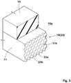
- FIG. 3 is a perspective view of the adhesion prevention portion 19 on the first end 10e side in another embodiment.
- the adhesion prevention portion 19 in the present embodiment is formed on the first side surface 17e of the sound absorption layer 11.
- the adhesion prevention portion 19 in the present embodiment is formed so as to include a recessed and projecting portion 23 which allows reduction in the area of contact between the first side surface 17e and the first exposed portion (not shown). Such a recessed and projecting portion 23 can also prevent adhesion between the first side surface 17e and the first exposed portion 13A.
- the recessed and projecting portion 23 in the present embodiment is formed in an embossed pattern.
- the recessed and projecting portion 23 is formed by, for example, repetition of projecting portions 23a projecting outward in the tire axial direction and recessed portions 23b recessed inward in the tire axial direction.
- the projecting portions 23a in the present embodiment are formed in conical shapes.
- the recessed portions 23b in the present embodiment are formed in inverse conical shapes obtained by inverting the projecting portions 23a.
- the recessed and projecting portion 23 in the present embodiment is formed in a wavy shape in which the projecting portions 23a and the recessed portions 23b are continuous with each other.
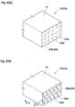
- FIGS. 4(A) and (B) are enlarged views of a recessed and projecting portion 23 in still another embodiment.
- the recessed and projecting portion 23 may be formed by a planarly extending flat surface portion 24 being dotted with the projecting portions 23a (in this case, the flat surface portion 24 corresponds to the recessed portions 23b).
- the recessed and projecting portion 23 may be formed by the flat surface portion 24 being dotted with the recessed portions 23b having inverse conical shapes (in this case, the flat surface portion 24 corresponds to the projecting portions 23a).
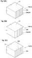
- FIGS. 5(A) to (C) are enlarged views of a recessed and projecting portion 23 in still another embodiment.
- the recessed and projecting portion 23 in the present embodiment is formed into a rib-like body.
- the recessed and projecting portion 23 may be formed by arranging, on the flat surface portion 24, rib-like projecting portions 23a extending in the tire radial direction (in this case, the flat surface portion 24 corresponds to the recessed portions 23b).
- the flat surface portion 24 corresponds to the recessed portions 23b.
- the recessed and projecting portion 23 may be formed by arranging, in the flat surface portion 24, groove-like recessed portions 23b extending in the tire radial direction (in this case, the flat surface portion 24 corresponds to the projecting portions 23a). Still alternatively, as shown in FIG. 5(C) , the recessed and projecting portion 23 may be formed by smooth repetition of the rib-like projecting portions 23a and the groove-like recessed portions 23b extending in the tire radial direction, without having the flat surface portion 24.
- the recessed and projecting portion 23 is not limited to these forms, but may be obtained by, for example, alternately forming the projecting portions 23a on, and the recessed portions 23b in, the flat surface portion 24 (not shown).
- the shapes of the projecting portions 23a and the recessed portions 23b are not limited to the conical shapes and the rib shapes, but various shapes such as shapes of a column, a quadrangular prism, and a quadrangular pyramid can be used, for example.
- the first side surface 17e may include, as the adhesion prevention portion 19, the layer 20 formed of the mold-release material and the recessed and projecting portion 23 (not shown).
- the height h of the recessed and projecting portion 23 is preferably 1 to 7 mm. The height h is the distance in the width direction f of the sound absorption layer 11 between each projecting portion 23a and the corresponding recessed portion 23b.
- FIG. 6 is a cross-sectional view of the first end 10e side of the tire 1 in still another embodiment. Components common to the above-described embodiments and the present embodiment are denoted by the same reference characters, and the description thereof will be omitted.
- the adhesion prevention portion 19 is disposed on the first exposed portion 13A in the present embodiment. Accordingly, adhesion with the first side surface 17e is prevented on the first exposed portion 13A side.
- the adhesion prevention portion 19 in the present embodiment includes, for example, a layer 20 formed of a mold-release material.
- the layer 20 is formed by applying the mold-release material.
- the method for applying the mold-release material is not particularly limited, and various methods such as methods using a brush, a roller, and a spray can be employed.
- the layer 20 can be formed by, for example, a film that contains silicone, polyethylene, or the like.
- the adhesion prevention portion 19 may be formed by applying a material for reducing the adhesiveness of the sealant layer 10. Talc and the like are suitable as the material for reducing the adhesiveness.
- the layer 20 is preferably formed so as to have a uniform thickness, and preferably has a thickness of about, for example, 5 to 100 ⁇ m.
- the adhesion prevention portion 19 only has to be disposed over a region B within which the portion, of the first side surface 17e, that extends over the range from the inner end 21 in the tire radial direction of the first side surface 17e to the position corresponding to not less than 20% of the thickness ta (shown in FIG. 3 ) at the first side surface 17e comes into contact with the first exposed portion 13A at the time of contact-involving deformation.
- the contact-involving deformation refers to deformation owing to which the first side surface 17e rotates to the first end 10e side about the outer end 22 in the tire radial direction of the first side surface 17e and comes into contact with the first exposed portion 13A.
- FIG. 7 is a cross-sectional view of the first end 10e side of the tire 1 in still another embodiment.
- the adhesion prevention portion 19 is disposed on each of the first side surface 17e and the first exposed portion 13A in the present embodiment. Accordingly, the adhesion between the first side surface 17e and the first exposed portion 13A is more likely to be prevented, whereby excellent air-seal performance can be exhibited.
- the adhesion prevention portion 19 disposed on the first side surface 17e is preferably at least one of the layer 20 formed of the mold-release material and the recessed and projecting portion 23.
- the adhesion prevention portion 19 disposed on the first exposed portion 13A is preferably the layer 20 formed of the mold-release material.
- Pneumatic tires having the basic structure in FIG. 1 were manufactured based on the specifications in Table 1, and each pneumatic tire was tested for air-seal performance. Specifications that are common to the tires, and a test method are described as follows. Thickness t2 of sealant layer: 3 mm
- Producing method for sealant layer a method that involves affixing a substantially string-shaped sealant material using a twin-screw continuous kneader Blending formula of sealant material (per 100 parts by mass of butyl rubber)
- Mold-release material KF96 or KF96SP manufactured by Shin-Etsu Chemical Co., Ltd.
- Sponge material an ether-based polyurethane sponge (specific gravity: 0.04)
- the width Wb in the tire axial direction of the sound absorption layer is shown in FIG. 1 .
- Running was performed with each tire on a drum having a diameter of 1.7 m under the following conditions. Then, 50 nails each having a body diameter of 5 mm were knocked into the tire so as to pierce a covered portion, and the nails were pulled out three minutes later. Thereafter, soapy water was sprayed on the tire, and a visual check was performed as to whether air leakage had occurred. The result is indicated as the number of locations at which air leakage had occurred. A smaller numeric value indicates better air-seal performance.
- the tire of each example has better air-seal performance than the tire of each comparative example.
- the same results were obtained oven when the sound absorption layer, the sealant layer, the mold-release material, or the recessed and projecting portion were changed within the scope of the preferable mode.
- the tire of the example maintains excellent road noise performance since the sound absorption layer is made less flat than in the tire of the comparative example.
Landscapes
- Engineering & Computer Science (AREA)
- Mechanical Engineering (AREA)
- Tires In General (AREA)
Applications Claiming Priority (1)
| Application Number | Priority Date | Filing Date | Title |
|---|---|---|---|
| JP2018217495A JP7205186B2 (ja) | 2018-11-20 | 2018-11-20 | 空気入りタイヤ |
Publications (2)
| Publication Number | Publication Date |
|---|---|
| EP3656583A1 true EP3656583A1 (fr) | 2020-05-27 |
| EP3656583B1 EP3656583B1 (fr) | 2021-09-01 |
Family
ID=68609967
Family Applications (1)
| Application Number | Title | Priority Date | Filing Date |
|---|---|---|---|
| EP19209698.0A Active EP3656583B1 (fr) | 2018-11-20 | 2019-11-18 | Pneumatique |
Country Status (2)
| Country | Link |
|---|---|
| EP (1) | EP3656583B1 (fr) |
| JP (1) | JP7205186B2 (fr) |
Cited By (2)
| Publication number | Priority date | Publication date | Assignee | Title |
|---|---|---|---|---|
| EP4056387A1 (fr) * | 2021-03-09 | 2022-09-14 | Sumitomo Rubber Industries, Ltd. | Pneumatique |
| EP4163131A1 (fr) * | 2021-10-06 | 2023-04-12 | Kumho Tire Co., Inc. | Pneumatique et son procédé de fabrication |
Citations (4)
| Publication number | Priority date | Publication date | Assignee | Title |
|---|---|---|---|---|
| US20100307655A1 (en) * | 2009-06-05 | 2010-12-09 | The Yokohama Rubber Co., Ltd. | Pneumatic tire |
| DE102014206009A1 (de) * | 2014-03-31 | 2015-10-01 | Continental Reifen Deutschland Gmbh | Fahrzeugluftreifen |
| EP3199382A1 (fr) * | 2014-10-17 | 2017-08-02 | Sumitomo Rubber Industries, Ltd. | Bandage pneumatique et procédé de production de bandage pneumatique |
| WO2017163219A1 (fr) * | 2016-03-25 | 2017-09-28 | Pirelli Tyre S.P.A. | Pneu auto-obturant insonorisé pour roues de véhicule |
Family Cites Families (4)
| Publication number | Priority date | Publication date | Assignee | Title |
|---|---|---|---|---|
| JP2008168648A (ja) | 2007-01-05 | 2008-07-24 | Yokohama Rubber Co Ltd:The | 空気入りタイヤ |
| FR2953760B1 (fr) | 2009-12-14 | 2013-01-11 | Michelin Soc Tech | Bandage pneumatique avec couche auto-obturante integree |
| DE102015212105A1 (de) | 2015-01-13 | 2016-07-14 | Continental Reifen Deutschland Gmbh | Fahrzeugluftreifen |
| DE102015221698A1 (de) | 2015-11-05 | 2017-05-11 | Continental Reifen Deutschland Gmbh | Fahrzeugluftreifen |
-
2018
- 2018-11-20 JP JP2018217495A patent/JP7205186B2/ja active Active
-
2019
- 2019-11-18 EP EP19209698.0A patent/EP3656583B1/fr active Active
Patent Citations (4)
| Publication number | Priority date | Publication date | Assignee | Title |
|---|---|---|---|---|
| US20100307655A1 (en) * | 2009-06-05 | 2010-12-09 | The Yokohama Rubber Co., Ltd. | Pneumatic tire |
| DE102014206009A1 (de) * | 2014-03-31 | 2015-10-01 | Continental Reifen Deutschland Gmbh | Fahrzeugluftreifen |
| EP3199382A1 (fr) * | 2014-10-17 | 2017-08-02 | Sumitomo Rubber Industries, Ltd. | Bandage pneumatique et procédé de production de bandage pneumatique |
| WO2017163219A1 (fr) * | 2016-03-25 | 2017-09-28 | Pirelli Tyre S.P.A. | Pneu auto-obturant insonorisé pour roues de véhicule |
Cited By (2)
| Publication number | Priority date | Publication date | Assignee | Title |
|---|---|---|---|---|
| EP4056387A1 (fr) * | 2021-03-09 | 2022-09-14 | Sumitomo Rubber Industries, Ltd. | Pneumatique |
| EP4163131A1 (fr) * | 2021-10-06 | 2023-04-12 | Kumho Tire Co., Inc. | Pneumatique et son procédé de fabrication |
Also Published As
| Publication number | Publication date |
|---|---|
| JP7205186B2 (ja) | 2023-01-17 |
| EP3656583B1 (fr) | 2021-09-01 |
| JP2020082905A (ja) | 2020-06-04 |
Similar Documents
| Publication | Publication Date | Title |
|---|---|---|
| JP6544373B2 (ja) | シーラントタイヤ | |
| JP6900450B2 (ja) | シーラント層及び吸音材層を含むタイヤ | |
| US8151845B2 (en) | Tire with reduced rolling noise | |
| JP2011020479A (ja) | 制音体付空気入りタイヤ | |
| US20100307655A1 (en) | Pneumatic tire | |
| KR101328238B1 (ko) | 공기 타이어와 림의 조립체 | |
| EP3656583A1 (fr) | Pneumatique | |
| JP3964878B2 (ja) | 空気入りタイヤとリムとの組立体 | |
| EP1666274B1 (fr) | Pneumatique et son procédé de fabrication | |
| JP4971722B2 (ja) | 空気入りタイヤ | |
| EP3925803A1 (fr) | Pneu comprenant une couche d'étanchéité et une couche absorbante acoustique | |
| WO2003020539A1 (fr) | Pneumatique et son procede de production | |
| EP3895912B1 (fr) | Pneumatique | |
| JP2009039901A (ja) | 空気入りタイヤの製造方法及び空気入りタイヤ | |
| EP3904118A1 (fr) | Pneumatique | |
| JP3837375B2 (ja) | セルフシールタイヤの製造方法 | |
| JP2869323B2 (ja) | 乗用車用スチールラジアルタイヤ | |
| EP3431310B1 (fr) | Pneu et son procédé de fabrication | |
| JPS5936675B2 (ja) | タイヤのパンク自閉層 | |
| WO2004076207A1 (fr) | Pneumatique et son procede de fabrication | |
| EP4056387A1 (fr) | Pneumatique | |
| JP7135828B2 (ja) | タイヤの試験方法 | |
| JP2023097900A (ja) | 空気入りタイヤ | |
| JP6939777B2 (ja) | 空気入りタイヤ | |
| JP2024062218A (ja) | 空気入りタイヤ |
Legal Events
| Date | Code | Title | Description |
|---|---|---|---|
| PUAI | Public reference made under article 153(3) epc to a published international application that has entered the european phase |
Free format text: ORIGINAL CODE: 0009012 |
|
| STAA | Information on the status of an ep patent application or granted ep patent |
Free format text: STATUS: THE APPLICATION HAS BEEN PUBLISHED |
|
| AK | Designated contracting states |
Kind code of ref document: A1 Designated state(s): AL AT BE BG CH CY CZ DE DK EE ES FI FR GB GR HR HU IE IS IT LI LT LU LV MC MK MT NL NO PL PT RO RS SE SI SK SM TR |
|
| AX | Request for extension of the european patent |
Extension state: BA ME |
|
| STAA | Information on the status of an ep patent application or granted ep patent |
Free format text: STATUS: REQUEST FOR EXAMINATION WAS MADE |
|
| 17P | Request for examination filed |
Effective date: 20201113 |
|
| RBV | Designated contracting states (corrected) |
Designated state(s): AL AT BE BG CH CY CZ DE DK EE ES FI FR GB GR HR HU IE IS IT LI LT LU LV MC MK MT NL NO PL PT RO RS SE SI SK SM TR |
|
| GRAP | Despatch of communication of intention to grant a patent |
Free format text: ORIGINAL CODE: EPIDOSNIGR1 |
|
| STAA | Information on the status of an ep patent application or granted ep patent |
Free format text: STATUS: GRANT OF PATENT IS INTENDED |
|
| RIC1 | Information provided on ipc code assigned before grant |
Ipc: B60C 19/00 20060101AFI20210225BHEP Ipc: B60C 19/12 20060101ALI20210225BHEP |
|
| INTG | Intention to grant announced |
Effective date: 20210323 |
|
| GRAS | Grant fee paid |
Free format text: ORIGINAL CODE: EPIDOSNIGR3 |
|
| GRAA | (expected) grant |
Free format text: ORIGINAL CODE: 0009210 |
|
| STAA | Information on the status of an ep patent application or granted ep patent |
Free format text: STATUS: THE PATENT HAS BEEN GRANTED |
|
| AK | Designated contracting states |
Kind code of ref document: B1 Designated state(s): AL AT BE BG CH CY CZ DE DK EE ES FI FR GB GR HR HU IE IS IT LI LT LU LV MC MK MT NL NO PL PT RO RS SE SI SK SM TR |
|
| REG | Reference to a national code |
Ref country code: GB Ref legal event code: FG4D |
|
| REG | Reference to a national code |
Ref country code: CH Ref legal event code: EP Ref country code: AT Ref legal event code: REF Ref document number: 1425847 Country of ref document: AT Kind code of ref document: T Effective date: 20210915 |
|
| REG | Reference to a national code |
Ref country code: DE Ref legal event code: R096 Ref document number: 602019007351 Country of ref document: DE |
|
| REG | Reference to a national code |
Ref country code: IE Ref legal event code: FG4D |
|
| REG | Reference to a national code |
Ref country code: LT Ref legal event code: MG9D |
|
| REG | Reference to a national code |
Ref country code: NL Ref legal event code: MP Effective date: 20210901 |
|
| PG25 | Lapsed in a contracting state [announced via postgrant information from national office to epo] |
Ref country code: SE Free format text: LAPSE BECAUSE OF FAILURE TO SUBMIT A TRANSLATION OF THE DESCRIPTION OR TO PAY THE FEE WITHIN THE PRESCRIBED TIME-LIMIT Effective date: 20210901 Ref country code: RS Free format text: LAPSE BECAUSE OF FAILURE TO SUBMIT A TRANSLATION OF THE DESCRIPTION OR TO PAY THE FEE WITHIN THE PRESCRIBED TIME-LIMIT Effective date: 20210901 Ref country code: ES Free format text: LAPSE BECAUSE OF FAILURE TO SUBMIT A TRANSLATION OF THE DESCRIPTION OR TO PAY THE FEE WITHIN THE PRESCRIBED TIME-LIMIT Effective date: 20210901 Ref country code: LT Free format text: LAPSE BECAUSE OF FAILURE TO SUBMIT A TRANSLATION OF THE DESCRIPTION OR TO PAY THE FEE WITHIN THE PRESCRIBED TIME-LIMIT Effective date: 20210901 Ref country code: BG Free format text: LAPSE BECAUSE OF FAILURE TO SUBMIT A TRANSLATION OF THE DESCRIPTION OR TO PAY THE FEE WITHIN THE PRESCRIBED TIME-LIMIT Effective date: 20211201 Ref country code: NO Free format text: LAPSE BECAUSE OF FAILURE TO SUBMIT A TRANSLATION OF THE DESCRIPTION OR TO PAY THE FEE WITHIN THE PRESCRIBED TIME-LIMIT Effective date: 20211201 Ref country code: FI Free format text: LAPSE BECAUSE OF FAILURE TO SUBMIT A TRANSLATION OF THE DESCRIPTION OR TO PAY THE FEE WITHIN THE PRESCRIBED TIME-LIMIT Effective date: 20210901 Ref country code: HR Free format text: LAPSE BECAUSE OF FAILURE TO SUBMIT A TRANSLATION OF THE DESCRIPTION OR TO PAY THE FEE WITHIN THE PRESCRIBED TIME-LIMIT Effective date: 20210901 |
|
| REG | Reference to a national code |
Ref country code: AT Ref legal event code: MK05 Ref document number: 1425847 Country of ref document: AT Kind code of ref document: T Effective date: 20210901 |
|
| PG25 | Lapsed in a contracting state [announced via postgrant information from national office to epo] |
Ref country code: PL Free format text: LAPSE BECAUSE OF FAILURE TO SUBMIT A TRANSLATION OF THE DESCRIPTION OR TO PAY THE FEE WITHIN THE PRESCRIBED TIME-LIMIT Effective date: 20210901 Ref country code: LV Free format text: LAPSE BECAUSE OF FAILURE TO SUBMIT A TRANSLATION OF THE DESCRIPTION OR TO PAY THE FEE WITHIN THE PRESCRIBED TIME-LIMIT Effective date: 20210901 Ref country code: GR Free format text: LAPSE BECAUSE OF FAILURE TO SUBMIT A TRANSLATION OF THE DESCRIPTION OR TO PAY THE FEE WITHIN THE PRESCRIBED TIME-LIMIT Effective date: 20211202 |
|
| PG25 | Lapsed in a contracting state [announced via postgrant information from national office to epo] |
Ref country code: AT Free format text: LAPSE BECAUSE OF FAILURE TO SUBMIT A TRANSLATION OF THE DESCRIPTION OR TO PAY THE FEE WITHIN THE PRESCRIBED TIME-LIMIT Effective date: 20210901 |
|
| PG25 | Lapsed in a contracting state [announced via postgrant information from national office to epo] |
Ref country code: IS Free format text: LAPSE BECAUSE OF FAILURE TO SUBMIT A TRANSLATION OF THE DESCRIPTION OR TO PAY THE FEE WITHIN THE PRESCRIBED TIME-LIMIT Effective date: 20220101 Ref country code: SM Free format text: LAPSE BECAUSE OF FAILURE TO SUBMIT A TRANSLATION OF THE DESCRIPTION OR TO PAY THE FEE WITHIN THE PRESCRIBED TIME-LIMIT Effective date: 20210901 Ref country code: SK Free format text: LAPSE BECAUSE OF FAILURE TO SUBMIT A TRANSLATION OF THE DESCRIPTION OR TO PAY THE FEE WITHIN THE PRESCRIBED TIME-LIMIT Effective date: 20210901 Ref country code: RO Free format text: LAPSE BECAUSE OF FAILURE TO SUBMIT A TRANSLATION OF THE DESCRIPTION OR TO PAY THE FEE WITHIN THE PRESCRIBED TIME-LIMIT Effective date: 20210901 Ref country code: PT Free format text: LAPSE BECAUSE OF FAILURE TO SUBMIT A TRANSLATION OF THE DESCRIPTION OR TO PAY THE FEE WITHIN THE PRESCRIBED TIME-LIMIT Effective date: 20220103 Ref country code: NL Free format text: LAPSE BECAUSE OF FAILURE TO SUBMIT A TRANSLATION OF THE DESCRIPTION OR TO PAY THE FEE WITHIN THE PRESCRIBED TIME-LIMIT Effective date: 20210901 Ref country code: EE Free format text: LAPSE BECAUSE OF FAILURE TO SUBMIT A TRANSLATION OF THE DESCRIPTION OR TO PAY THE FEE WITHIN THE PRESCRIBED TIME-LIMIT Effective date: 20210901 Ref country code: CZ Free format text: LAPSE BECAUSE OF FAILURE TO SUBMIT A TRANSLATION OF THE DESCRIPTION OR TO PAY THE FEE WITHIN THE PRESCRIBED TIME-LIMIT Effective date: 20210901 Ref country code: AL Free format text: LAPSE BECAUSE OF FAILURE TO SUBMIT A TRANSLATION OF THE DESCRIPTION OR TO PAY THE FEE WITHIN THE PRESCRIBED TIME-LIMIT Effective date: 20210901 |
|
| REG | Reference to a national code |
Ref country code: DE Ref legal event code: R097 Ref document number: 602019007351 Country of ref document: DE |
|
| PG25 | Lapsed in a contracting state [announced via postgrant information from national office to epo] |
Ref country code: MC Free format text: LAPSE BECAUSE OF FAILURE TO SUBMIT A TRANSLATION OF THE DESCRIPTION OR TO PAY THE FEE WITHIN THE PRESCRIBED TIME-LIMIT Effective date: 20210901 |
|
| PLBE | No opposition filed within time limit |
Free format text: ORIGINAL CODE: 0009261 |
|
| STAA | Information on the status of an ep patent application or granted ep patent |
Free format text: STATUS: NO OPPOSITION FILED WITHIN TIME LIMIT |
|
| PG25 | Lapsed in a contracting state [announced via postgrant information from national office to epo] |
Ref country code: LU Free format text: LAPSE BECAUSE OF NON-PAYMENT OF DUE FEES Effective date: 20211118 Ref country code: IT Free format text: LAPSE BECAUSE OF FAILURE TO SUBMIT A TRANSLATION OF THE DESCRIPTION OR TO PAY THE FEE WITHIN THE PRESCRIBED TIME-LIMIT Effective date: 20210901 Ref country code: DK Free format text: LAPSE BECAUSE OF FAILURE TO SUBMIT A TRANSLATION OF THE DESCRIPTION OR TO PAY THE FEE WITHIN THE PRESCRIBED TIME-LIMIT Effective date: 20210901 Ref country code: BE Free format text: LAPSE BECAUSE OF NON-PAYMENT OF DUE FEES Effective date: 20211130 |
|
| REG | Reference to a national code |
Ref country code: BE Ref legal event code: MM Effective date: 20211130 |
|
| 26N | No opposition filed |
Effective date: 20220602 |
|
| PG25 | Lapsed in a contracting state [announced via postgrant information from national office to epo] |
Ref country code: SI Free format text: LAPSE BECAUSE OF FAILURE TO SUBMIT A TRANSLATION OF THE DESCRIPTION OR TO PAY THE FEE WITHIN THE PRESCRIBED TIME-LIMIT Effective date: 20210901 |
|
| PG25 | Lapsed in a contracting state [announced via postgrant information from national office to epo] |
Ref country code: IE Free format text: LAPSE BECAUSE OF NON-PAYMENT OF DUE FEES Effective date: 20211118 |
|
| P01 | Opt-out of the competence of the unified patent court (upc) registered |
Effective date: 20230510 |
|
| PG25 | Lapsed in a contracting state [announced via postgrant information from national office to epo] |
Ref country code: CY Free format text: LAPSE BECAUSE OF FAILURE TO SUBMIT A TRANSLATION OF THE DESCRIPTION OR TO PAY THE FEE WITHIN THE PRESCRIBED TIME-LIMIT Effective date: 20210901 |
|
| REG | Reference to a national code |
Ref country code: CH Ref legal event code: PL |
|
| PG25 | Lapsed in a contracting state [announced via postgrant information from national office to epo] |
Ref country code: LI Free format text: LAPSE BECAUSE OF NON-PAYMENT OF DUE FEES Effective date: 20221130 Ref country code: HU Free format text: LAPSE BECAUSE OF FAILURE TO SUBMIT A TRANSLATION OF THE DESCRIPTION OR TO PAY THE FEE WITHIN THE PRESCRIBED TIME-LIMIT; INVALID AB INITIO Effective date: 20191118 Ref country code: CH Free format text: LAPSE BECAUSE OF NON-PAYMENT OF DUE FEES Effective date: 20221130 |
|
| PGFP | Annual fee paid to national office [announced via postgrant information from national office to epo] |
Ref country code: FR Payment date: 20230929 Year of fee payment: 5 |
|
| PGFP | Annual fee paid to national office [announced via postgrant information from national office to epo] |
Ref country code: DE Payment date: 20230929 Year of fee payment: 5 |
|
| PG25 | Lapsed in a contracting state [announced via postgrant information from national office to epo] |
Ref country code: MK Free format text: LAPSE BECAUSE OF FAILURE TO SUBMIT A TRANSLATION OF THE DESCRIPTION OR TO PAY THE FEE WITHIN THE PRESCRIBED TIME-LIMIT Effective date: 20210901 |
|
| GBPC | Gb: european patent ceased through non-payment of renewal fee |
Effective date: 20231118 |