EP3656477A1 - Application system, operation system, and attitude changing unit - Google Patents
Application system, operation system, and attitude changing unit Download PDFInfo
- Publication number
- EP3656477A1 EP3656477A1 EP18901385.7A EP18901385A EP3656477A1 EP 3656477 A1 EP3656477 A1 EP 3656477A1 EP 18901385 A EP18901385 A EP 18901385A EP 3656477 A1 EP3656477 A1 EP 3656477A1
- Authority
- EP
- European Patent Office
- Prior art keywords
- unit
- pivot
- support
- nozzle
- application
- Prior art date
- Legal status (The legal status is an assumption and is not a legal conclusion. Google has not performed a legal analysis and makes no representation as to the accuracy of the status listed.)
- Withdrawn
Links
Images




Classifications
-
- B—PERFORMING OPERATIONS; TRANSPORTING
- B05—SPRAYING OR ATOMISING IN GENERAL; APPLYING FLUENT MATERIALS TO SURFACES, IN GENERAL
- B05C—APPARATUS FOR APPLYING FLUENT MATERIALS TO SURFACES, IN GENERAL
- B05C5/00—Apparatus in which liquid or other fluent material is projected, poured or allowed to flow on to the surface of the work
- B05C5/02—Apparatus in which liquid or other fluent material is projected, poured or allowed to flow on to the surface of the work the liquid or other fluent material being discharged through an outlet orifice by pressure, e.g. from an outlet device in contact or almost in contact, with the work
- B05C5/0208—Apparatus in which liquid or other fluent material is projected, poured or allowed to flow on to the surface of the work the liquid or other fluent material being discharged through an outlet orifice by pressure, e.g. from an outlet device in contact or almost in contact, with the work for applying liquid or other fluent material to separate articles
- B05C5/0212—Apparatus in which liquid or other fluent material is projected, poured or allowed to flow on to the surface of the work the liquid or other fluent material being discharged through an outlet orifice by pressure, e.g. from an outlet device in contact or almost in contact, with the work for applying liquid or other fluent material to separate articles only at particular parts of the articles
- B05C5/0216—Apparatus in which liquid or other fluent material is projected, poured or allowed to flow on to the surface of the work the liquid or other fluent material being discharged through an outlet orifice by pressure, e.g. from an outlet device in contact or almost in contact, with the work for applying liquid or other fluent material to separate articles only at particular parts of the articles by relative movement of article and outlet according to a predetermined path
-
- B—PERFORMING OPERATIONS; TRANSPORTING
- B05—SPRAYING OR ATOMISING IN GENERAL; APPLYING FLUENT MATERIALS TO SURFACES, IN GENERAL
- B05C—APPARATUS FOR APPLYING FLUENT MATERIALS TO SURFACES, IN GENERAL
- B05C5/00—Apparatus in which liquid or other fluent material is projected, poured or allowed to flow on to the surface of the work
- B05C5/02—Apparatus in which liquid or other fluent material is projected, poured or allowed to flow on to the surface of the work the liquid or other fluent material being discharged through an outlet orifice by pressure, e.g. from an outlet device in contact or almost in contact, with the work
- B05C5/0208—Apparatus in which liquid or other fluent material is projected, poured or allowed to flow on to the surface of the work the liquid or other fluent material being discharged through an outlet orifice by pressure, e.g. from an outlet device in contact or almost in contact, with the work for applying liquid or other fluent material to separate articles
-
- B—PERFORMING OPERATIONS; TRANSPORTING
- B05—SPRAYING OR ATOMISING IN GENERAL; APPLYING FLUENT MATERIALS TO SURFACES, IN GENERAL
- B05B—SPRAYING APPARATUS; ATOMISING APPARATUS; NOZZLES
- B05B13/00—Machines or plants for applying liquids or other fluent materials to surfaces of objects or other work by spraying, not covered by groups B05B1/00 - B05B11/00
- B05B13/02—Means for supporting work; Arrangement or mounting of spray heads; Adaptation or arrangement of means for feeding work
- B05B13/04—Means for supporting work; Arrangement or mounting of spray heads; Adaptation or arrangement of means for feeding work the spray heads being moved during spraying operation
- B05B13/0447—Installation or apparatus for applying liquid or other fluent material to conveyed separate articles
- B05B13/0457—Installation or apparatus for applying liquid or other fluent material to conveyed separate articles specially designed for applying liquid or other fluent material to three-dimensional [3D] surfaces of the work, e.g. by using several moving spray heads
-
- B—PERFORMING OPERATIONS; TRANSPORTING
- B05—SPRAYING OR ATOMISING IN GENERAL; APPLYING FLUENT MATERIALS TO SURFACES, IN GENERAL
- B05C—APPARATUS FOR APPLYING FLUENT MATERIALS TO SURFACES, IN GENERAL
- B05C11/00—Component parts, details or accessories not specifically provided for in groups B05C1/00 - B05C9/00
- B05C11/10—Storage, supply or control of liquid or other fluent material; Recovery of excess liquid or other fluent material
- B05C11/1002—Means for controlling supply, i.e. flow or pressure, of liquid or other fluent material to the applying apparatus, e.g. valves
-
- B—PERFORMING OPERATIONS; TRANSPORTING
- B05—SPRAYING OR ATOMISING IN GENERAL; APPLYING FLUENT MATERIALS TO SURFACES, IN GENERAL
- B05C—APPARATUS FOR APPLYING FLUENT MATERIALS TO SURFACES, IN GENERAL
- B05C11/00—Component parts, details or accessories not specifically provided for in groups B05C1/00 - B05C9/00
- B05C11/10—Storage, supply or control of liquid or other fluent material; Recovery of excess liquid or other fluent material
- B05C11/1002—Means for controlling supply, i.e. flow or pressure, of liquid or other fluent material to the applying apparatus, e.g. valves
- B05C11/1005—Means for controlling supply, i.e. flow or pressure, of liquid or other fluent material to the applying apparatus, e.g. valves responsive to condition of liquid or other fluent material already applied to the surface, e.g. coating thickness, weight or pattern
-
- B—PERFORMING OPERATIONS; TRANSPORTING
- B05—SPRAYING OR ATOMISING IN GENERAL; APPLYING FLUENT MATERIALS TO SURFACES, IN GENERAL
- B05C—APPARATUS FOR APPLYING FLUENT MATERIALS TO SURFACES, IN GENERAL
- B05C11/00—Component parts, details or accessories not specifically provided for in groups B05C1/00 - B05C9/00
- B05C11/10—Storage, supply or control of liquid or other fluent material; Recovery of excess liquid or other fluent material
- B05C11/1002—Means for controlling supply, i.e. flow or pressure, of liquid or other fluent material to the applying apparatus, e.g. valves
- B05C11/1015—Means for controlling supply, i.e. flow or pressure, of liquid or other fluent material to the applying apparatus, e.g. valves responsive to a conditions of ambient medium or target, e.g. humidity, temperature ; responsive to position or movement of the coating head relative to the target
-
- B—PERFORMING OPERATIONS; TRANSPORTING
- B05—SPRAYING OR ATOMISING IN GENERAL; APPLYING FLUENT MATERIALS TO SURFACES, IN GENERAL
- B05C—APPARATUS FOR APPLYING FLUENT MATERIALS TO SURFACES, IN GENERAL
- B05C13/00—Means for manipulating or holding work, e.g. for separate articles
- B05C13/02—Means for manipulating or holding work, e.g. for separate articles for particular articles
-
- B—PERFORMING OPERATIONS; TRANSPORTING
- B05—SPRAYING OR ATOMISING IN GENERAL; APPLYING FLUENT MATERIALS TO SURFACES, IN GENERAL
- B05C—APPARATUS FOR APPLYING FLUENT MATERIALS TO SURFACES, IN GENERAL
- B05C5/00—Apparatus in which liquid or other fluent material is projected, poured or allowed to flow on to the surface of the work
- B05C5/02—Apparatus in which liquid or other fluent material is projected, poured or allowed to flow on to the surface of the work the liquid or other fluent material being discharged through an outlet orifice by pressure, e.g. from an outlet device in contact or almost in contact, with the work
-
- B—PERFORMING OPERATIONS; TRANSPORTING
- B25—HAND TOOLS; PORTABLE POWER-DRIVEN TOOLS; MANIPULATORS
- B25J—MANIPULATORS; CHAMBERS PROVIDED WITH MANIPULATION DEVICES
- B25J11/00—Manipulators not otherwise provided for
- B25J11/0075—Manipulators for painting or coating
-
- B—PERFORMING OPERATIONS; TRANSPORTING
- B25—HAND TOOLS; PORTABLE POWER-DRIVEN TOOLS; MANIPULATORS
- B25J—MANIPULATORS; CHAMBERS PROVIDED WITH MANIPULATION DEVICES
- B25J9/00—Program-controlled manipulators
- B25J9/02—Program-controlled manipulators characterised by movement of the arms, e.g. cartesian coordinate type
- B25J9/023—Cartesian coordinate type
-
- B—PERFORMING OPERATIONS; TRANSPORTING
- B25—HAND TOOLS; PORTABLE POWER-DRIVEN TOOLS; MANIPULATORS
- B25J—MANIPULATORS; CHAMBERS PROVIDED WITH MANIPULATION DEVICES
- B25J9/00—Program-controlled manipulators
- B25J9/02—Program-controlled manipulators characterised by movement of the arms, e.g. cartesian coordinate type
- B25J9/04—Program-controlled manipulators characterised by movement of the arms, e.g. cartesian coordinate type by rotating at least one arm, excluding the head movement itself, e.g. cylindrical coordinate type or polar coordinate type
-
- B—PERFORMING OPERATIONS; TRANSPORTING
- B05—SPRAYING OR ATOMISING IN GENERAL; APPLYING FLUENT MATERIALS TO SURFACES, IN GENERAL
- B05B—SPRAYING APPARATUS; ATOMISING APPARATUS; NOZZLES
- B05B13/00—Machines or plants for applying liquids or other fluent materials to surfaces of objects or other work by spraying, not covered by groups B05B1/00 - B05B11/00
- B05B13/02—Means for supporting work; Arrangement or mounting of spray heads; Adaptation or arrangement of means for feeding work
- B05B13/04—Means for supporting work; Arrangement or mounting of spray heads; Adaptation or arrangement of means for feeding work the spray heads being moved during spraying operation
Definitions
- the present invention relates to a technique of performing an operation for a work and, for example, to an application system configured to apply a seal agent.
- PTL 1 proposes a system capable of applying a seal agent along the three-dimensional shape of a work by discharging the seal agent from a nozzle while changing the posture of the work.
- PTL 2 or 3 proposes a system capable of applying a seal agent along the three-dimensional shape of a work by fixing the work and causing a vertical articulated robot to move a nozzle for discharging the seal agent.
- an application system comprising:
- an operation system comprising:
- a posture changing unit provided to be movable in a vertical direction and at least one direction in a horizontal direction and configured to support an operation unit including an operation portion configured to perform an operation for an operation point of a work, wherein the operation portion is a solid or hollow shaft body, the posture changing unit includes:
- Fig. 1 is a schematic view of an operation system 1 according to an embodiment of the present invention.
- the operation system 1 according to this embodiment is an application system configured to apply a seal agent to one of two works, overlay the work on the other work, and bond them.
- Fig. 2 is a perspective view showing an example of works as processing targets.
- a work W2 is an attachment body to be attached to a work W1 as a main body, and is a cover to be placed on the upper side of the work W1 in this embodiment.
- a plurality of positioning holes HI are formed in the work W1, and a plurality of positioning holes H2 are formed in the work W2 in correspondence with the positions of the holes HI.
- the operation system 1 endlessly applies a seal agent 100 along an operation position (seal application position) Wp set on the peripheral edge of the work W1.
- the seal agent 100 is a kind of adhesive having a seal function.
- arrows X and Y represent horizontal directions orthogonal to each other, and an arrow Z indicates a vertical direction.
- the operation system 1 includes a plate-shaped base member 10 that forms the frame of the operation system and defines the occupation area of the operation system 1.
- the base member 10 has a rectangular shape long in the Y direction.
- the base member 10 is provided with an installation portion where a plurality of support columns 11 stand. In this embodiment, three lines of support columns 11 are provided apart in the Y direction, and two lines of support columns 11 are provided apart in the X direction.
- the installation portion is the peripheral edge region of the base member 10. An almost half region on one end side of the base member 10 in the Y direction, on which a support device 4 is installed, is an installation portion 10a, and an almost half region on the other end side, on which a support device 5 is installed, is an installation portion 10b.
- the installation portion 10a is a region surrounded by a total of four support columns 11 including two support columns 11 at the center in the Y direction and two support columns 11 on the one end side.
- the installation portion 10b is a region surrounded by a total of four support columns 11 including two support columns 11 at the center in the Y direction and two support columns 11 on the other end side.
- the support device 4 is a device configured to support the work W1.
- the work W1 is supported via a pallet 8 ( Fig. 7 or the like) to be described later.
- the support device 4 includes a pair of transfer mechanisms 4a, and a frame 4b that supports the pair of transfer mechanisms 4a.
- the pair of transfer mechanisms 4a are each extended in the X direction and arranged apart in the Y direction, and are mechanisms configured to convey the pallet 8 from one side to the other side in the X direction.
- the pair of transfer mechanisms 4a are arranged while continuing to conveyance mechanisms (not shown) arranged on both sides of the operation system 1 in the X direction.
- the pallet 8 (on which the unprocessed work W1 is placed) transferred by the conveyance mechanisms and the pair of transfer mechanisms 4a from the near side (one side) in Fig. 1 is transferred in the X direction from the outside of the system 1 to the inside. After processing, the pallet 8 (on which the works W1 and W2 bonded to each other are placed) is transferred in the X direction (other side) to the outside of the system 1.
- Each transfer mechanism 4a is, for example, a belt conveyor or a roller conveyor.
- the support device 4 is arranged under the moving range of movable units 31 and 60 to be described later.
- the support device 5 is a device configured to support the work W2.
- the work W2 is supported via the pallet 8 ( Fig. 7 or the like) to be described later.
- the support device 5 has the same arrangement as that of the support device 4, and includes a pair of transfer mechanisms 5a, and a frame 5b that supports the pair of transfer mechanisms 5a.
- the pair of transfer mechanisms 5a are each extended in the X direction and arranged apart in the Y direction, and are mechanisms configured to convey the pallet 8 from one side to the other side in the X direction.
- the pair of transfer mechanisms 5a are arranged while continuing to conveyance mechanisms (not shown) arranged on both sides of the operation system 1 in the X direction.
- the pallet 8 (on which the work W2 is placed) transferred by the conveyance mechanisms and the pair of transfer mechanisms 5a from the near side (one side) in Fig. 1 is transferred from the outside of the system 1 to the inside.
- Each transfer mechanism 5a is, for example, a belt conveyor or a roller conveyor.
- the support device 5 is arranged under the moving range of the movable unit 60 to be described later.
- the operation system 1 includes a moving device 3 that moves an operation unit 2.
- the moving device 3 includes the movable unit 31, a pair of guide frames 32, an elevating unit 33, and a posture changing unit 34.
- the pair of guide frames 32 function as a guide portion that guides the movement of the movable unit 31 in the Y direction.
- the pair of guide frames 32 are each extended in the Y direction and supported by the support columns 11 while being apart in the X direction.
- the movable unit 31 is a beam-shaped unit laid on the pair of guide frames 32.
- the movable unit 31 includes a support portion 31a extending in the X direction, and driving portions 31b arranged at the two ends of the support portion 31a in the X direction.
- Fig. 1 shows only one driving portion 31b.
- Each driving portion 31b includes a motor as a driving source, and exhibits a traveling force with respect to the guide frames 32.
- the guide frame 32 is provided with, for example, a rack or a ball screw shaft, and the driving portion 31b includes a pinion meshed with the rack or a ball nut meshed with the ball screw shaft.
- the movable unit 31 can translate in the Y direction by the guide of the pair of guide frames 32.
- a slider 31c is provided to be movable in the X direction.
- the support portion 31a functions as a guide frame that guides the movement of the slider 31c.
- the slider 31c is provided with a driving portion 31d.
- the driving portion 31d includes a motor as a driving source, and the slider 31c travels along the support portion 31a.
- the support portion 31a is provided with, for example, a rack or a ball screw shaft, and the driving portion 31d includes a pinion meshed with the rack or a ball nut meshed with the ball screw shaft.
- the movable unit 31 is a beam-shaped unit in this embodiment but may be a gate-shaped unit. In this case, an arrangement corresponding to the pair of guide frames 32 is supported on the base member 10 without using the plurality of support columns 11.
- the elevating unit 33 is fixed to the slider 31c. When the slider 31c moves, the elevating unit 33 is moved in the X direction along the support portion 31a.
- the elevating unit 33 includes a driving portion 33a.
- the driving portion 33a includes a motor as a driving source.
- the posture changing unit 34 and the operation unit 2 are moved (raised and lowered) in the Z direction by the driving force of the motor.
- As the elevating mechanism a ball screw mechanism or a rack-pinion mechanism can be employed.
- the operation unit 2 and the posture changing unit 34 can translate in the X, Y, and Z directions.
- the operation unit 2 and the posture changing unit 34 are movable in two horizontal directions (X and Y). As for the horizontal direction, they may be movable only in the X direction or only in the Y direction in accordance with the purpose of an operation.
- Fig. 3 is a perspective view of the posture changing unit 34 and the operation unit 2 supported by the posture changing unit 34.
- Fig. 4 shows a state in which a cover 36d of the posture changing unit 34 is detached in the perspective view of Fig. 3 .
- Fig. 5 is a perspective view of the posture changing unit 34 and the operation unit 2 viewed from a different line of sight, and also shows the outer appearance of a measuring unit 7.
- the operation unit 2 is an application unit that applies the seal agent 100 to the work W1.
- the operation unit 2 includes a nozzle 21 that discharges the seal agent 100, and a supply portion 22 that supplies the seal agent 100 (see Fig. 2 ) to the nozzle 21.
- the operation unit 2 includes an application control apparatus (a control apparatus 9B shown in Fig. 12 ) that controls discharge of the seal agent 100 from the nozzle 21.
- the nozzle 21 is an operation portion that performs an operation of discharging the seal agent 100.
- the nozzle 21 is a hollow shaft body, and is a cylindrical tube including a distal end portion 21a and a proximal end portion 21b. The proximal end portion 21b is connected to the supply portion 22, and the seal agent 100 is supplied from the supply portion 22.
- the seal agent 100 pressure-fed by the supply portion 22 to the proximal end portion 21b is discharged from the opening of the distal end portion 21a.
- the supply portion 22 is connected to the supply source (not shown) of the seal agent 100 via a pipe.
- the supply portion 22 includes a storage portion that stores the seal agent 100, and a driving mechanism that pressure-feeds the seal agent 100 in the storage portion to the nozzle 21.
- the control apparatus 9B controls the start and stop of discharge of the seal agent 100 from the nozzle 21, and the discharge amount of the seal agent 100.
- the control apparatus 9B communicates with a control apparatus 9A ( Fig. 12 ) (to be described later) that controls the operations of the moving device 3 and the posture changing unit 34, and controls the discharge amount of the seal agent 100 in accordance with the moving speed of the distal end of the nozzle 21.
- a control apparatus 9A Fig. 12
- the control apparatus 9B controls the influence of the temperature of the seal agent or a pressure change in a supply path to supply the seal agent can be prevented, and the discharge amount of the seal agent 100 can more accurately be controlled.
- the operation unit 2 a known application unit can be employed.
- the measuring unit 7 is a sensor configured to measure the application state of the seal agent 100 discharged from the nozzle 21.
- the measuring unit 7 is a range finder that emits a laser beam 7a and measures reflected light.
- the irradiation destination of the laser beam 7a is set on an almost extended line in the axial direction of the nozzle 21.
- the shape (thickness, width, and the like) of the seal agent 100 discharged onto the work W1 is monitored by the measuring unit 7, it is possible to determine whether the seal agent 100 is appropriately applied or not, for example, whether a discharge error of the seal agent 100 has occurred or not.
- the thickness the height of the applied seal agent 100 is monitored with reference to the seal application position Wp.
- Concerning the width the width of the applied seal agent 100 is monitored with reference to a preset installation value, thereby performing the determination.
- the posture changing unit 34 includes an upper frame 34a, a lower frame 34c, and a connecting portion 34b that connects them such that they can pivot about an axis ZA in the Z direction.
- the upper frame 34a is fixed to the lower end of the elevating unit 33, and the posture changing unit 34, the operation unit 2 and the measuring unit 7 are raised and lowered as a whole by the elevating unit 33.
- the upper frame 34a is provided with a pivot mechanism 35.
- the pivot mechanism 35 is a mechanism configured to make the lower frame 34c pivot about the axis ZA with respect to the upper frame 34a, and includes a motor 35a that is a driving source, and a transmission mechanism 35b.
- the transmission mechanism 35a is, for example, a belt transmission mechanism, and includes a driving pulley to be driven by the motor 35a, and a driven pulley on the rotating shaft side, which is provided in the connecting portion 34b and fixed to the lower frame 34c.
- the lower frame 34c is made to pivot about the axis ZA by driving the motor 35a.
- the lower frame 34c includes a plate-shaped horizontal support member 34d, and a plate-shaped vertical support member 34e.
- the end of the horizontal support member 34d on one side and the upper end of the vertical support member 34e are connected, and these members are combined in an inverted L shape.
- the connecting portion 34b (its rotating shaft) is connected to the center portion of the horizontal support member 34d.
- the upper end of the vertical support member 34e is fixed to the end of the horizontal support member 34d on one side and extended downward.
- the lower end of the vertical support member 34e is provided with a cylindrical pivotal support portion 34f extending in the horizontal direction, and a support member 37 is connected via the pivotal support portion 34f.
- the support member 37 is a member that supports the operation unit 2 and the measuring unit 7.
- the support member 37 is located on the lower side of the lower frame 34c having the inverted L shape, and includes a fixed portion 37a to which a side portion of the supply portion 22 of the operation unit 2 is fixed, and a fixed portion 37b to which the measuring unit 7 is fixed.
- the fixed portion 37a is a plate-shaped member, and the fixed portion 37b is a bracket attached to the plate-shaped member that forms the fixed portion 37a.
- a shaft-shaped connecting portion 37c extending in the horizontal direction is provided at the lower end of the support member 37.
- the connecting portion 37c is coaxially connected to the pivotal support portion 34f.
- the support member 37 can pivot about an axis XA in the horizontal direction, which is the center axis of the pivotal support portion 34f and the connecting portion 37c. That is, the operation unit 2, the measuring unit 7, and the support member 37 can integrally pivot about the axis XA.
- the vertical support member 34e is provided with a pivot mechanism 36.
- the pivot mechanism 36 is a mechanism that makes the support member 37 pivot about the axis ZX with respect to the lower frame 34c, and includes a motor 36a that is a driving source, a transmission mechanism 36e, a transmission mechanism 36b, and a rotating shaft 36c.
- the motor 36a is arranged on the other side surface (the surface on the lower side of the lower frame 34c having the inverted L shape) of the vertical support member 34e, and the transmission mechanism 36b and the rotating shaft 36c are arranged on one side surface of the vertical support member 34e.
- the transmission mechanism 36e is a relay transmission mechanism that transmits the driving force of the motor 36a to the transmission mechanism 36b, and is formed on the vertical support member 34e.
- the transmission mechanism 36e includes a transmission element 36g (for example, a reduction gear) that is provided between the motor 36a and a driving gear 362 and transmits the driving force of the motor 36a at a predetermined ratio.
- the transmission element 36g includes a transmission input portion (not shown) connected to the output shaft of the motor 36a, a transmission output portion 36go to which the driving gear 362 is connected, and a transmission attachment portion (not shown) attached to the vertical support member 34e.
- the transmission output portion 36go is rotatably attached to the vertical support member 34e via an opening formed in the vertical support member 34e.
- the rotating shaft 36c is a horizontal shaft fixed to the connecting portion 37c and is located at the lower end of the vertical support member 34e.
- the transmission mechanism 36b is a rack-pinion mechanism including the driving gear 362, a rack 363, and driven gears 361 and 364.
- the driving gear 362 is meshed with the rack 363.
- the rack 363 is a member with gear teeth arranged in the Z direction and is fixed to one side surface of a plate-shaped bracket 363a.
- the other side surface of the bracket 363a is provided with a plurality of sliders 363b arranged apart in the Z direction.
- a rail member 363c extending in the Z direction is fixed to the vertical support member 34e.
- the plurality of sliders 363b are engaged with the rail member 363c and slid along the rail member 363c.
- the rack 363 is supported by the vertical support member 34e to be movable in the Z direction.
- the pivotal movement of the driving gear 362 caused by the driving of the motor 36a is transmitted to the rack 363, and the rack 363 is moved in the vertical direction.
- the transmission mechanism 36b is not limited to the rack-pinion mechanism, and may be a transmission mechanism of another type such as a belt transmission mechanism.
- the driven gear 361 is supported on the lower portion of the vertical support member 34e to be rotatable with respect to the vertical support member 34e, and is meshed with the rack 363.
- the driven gear 364 is fixed to an end of the rotating shaft 36c and meshed with the driven gear 361.
- the driven gear 364 is connected to the connecting portion 37c via the rotating shaft 36c.
- the rotation of the driving gear 362 is transmitted to the driven gear 364 via the rack 363 and the driven gear 361 and further transmitted to the connecting portion 37c via the rotating shaft 36c.
- the pivotal support portion 34f is provided at the lower end of the vertical support member 34e to support the connecting portion 37c.
- the motor 36a is arranged on the upper side of the lower end of the vertical support member 34e, particularly, on the upper portion of the vertical support member 34e. In other words, the motor 36a is arranged at a position apart upward from the nozzle 21. This helps in preventing the motor 36a from interfering with the work W1 when the seal agent 100 is discharged from the nozzle 21 to the work W1.
- the motor 36a is one of components with large sizes among the members that constitute the device, and is one of components whose interference with the work W1 should be taken into consideration.
- the transmission mechanism 36b is provided to keep the motor 36a apart from the nozzle 21. It is therefore possible to prevent the motor 36a and the work W1 from interfering with each other and make the nozzle 21 approach the work W1 and discharge the seal agent 100.
- the periphery of the transmission mechanism 36b is covered with the cover 36d, whereby sticking of foreign substances to the transmission mechanism 36b is suppressed.
- the cover 36d is fixed to the vertical support member 34e.
- the pivot mechanism 35 makes the operation unit 2 pivot about the axis ZA
- the pivot mechanism 36 makes the operation unit 2 pivot about the axis XA. It is therefore possible to change the direction of the nozzle 21, that is, the discharge direction of the seal agent 100 to an arbitrary direction.
- the measuring unit 7 is made to pivot integrally with the operation unit 2 while maintaining the relative positional relationship to the operation unit 2, it is possible to always stably measure the application state of the seal agent 100 without depending on the posture of the operation unit 2.
- Fig. 5 shows a case in which the operation unit 2 is in an initial posture (or reference posture) in which the axial direction of the nozzle 21 is directed downward in the Z direction.
- the initial posture or reference posture
- the center axis of the nozzle 21 and the axis ZA are located on the same axis.
- the axis ZA and the axis XA cross on a portion 21c of the nozzle 21.
- the position of the distal end portion 21a when the posture of the operation unit 2 is changed can easily be obtained by calculation. For this reason, for example, even if the posture of the operation unit 2 is changed, the distance between the position of the distal end portion 21a and the seal application position Wp can be maintained at a distance at which the they do not interfere with each other, and the seal agent to be supplied can stably be supplied. As a result, application control of the seal agent 100 to the work W1 can relatively easily be performed.
- the discharge amount of the seal agent 100 is controlled in accordance with the moving speed (a speed obtained by adding the moving speed of the operation unit 2 by the moving device 3 to the peripheral speed of the distal end portion 21a about the axis XA) of the distal end portion 21a in posture change (in particular, a posture change about the axis XA) of the nozzle 21.
- the portion 21c is at a position apart from both the distal end portion 21a and the proximal end portion 21b, and is located at the intermediate portion of the nozzle 21 in the axial direction.
- the portion 21c that is the intersection between the axis ZA (the center axis of the nozzle 21 in the initial posture) and the axis XA is not limited to this embodiment, and may be located at, for example, the distal end portion 21a. In this case, even if the posture of the operation unit 2 is changed, and the posture of the nozzle 21 is changed, the position of the distal end portion 21a of the nozzle 21 is always constant. It is therefore unnecessary to perform calculation and control of the application position of the seal agent 100 to the work W1.
- the portion 21c is preferably a portion apart from the distal end portion 21a to the side of the proximal end portion 21b.
- the portion 21c that is the intersection between the axis ZA and the axis XA may be located in the proximal end portion 21b.
- the distal end portion 21a of the nozzle 21 can be made to sufficiently approach the work W1.
- the change amount of the position of the distal end portion 21a becomes large. For this reason, depending on the shape of the work W1, it may be difficult to continuously apply the seal agent 100 while moving the operation unit 2.
- the operation system 1 includes a conveyance device 6 configured to convey the work W2 from the support device 5 to the support device 4.
- the conveyance device 6 includes the movable unit 60, an elevating unit 61, a pivot unit 62, and a holding unit 63.
- the pair of guide frames 32 are also used as a guide portion that guides the movement of the movable unit 60 in the Y direction.
- a guide portion exclusive for the movable unit 60 may be provided.
- the movable unit 60 is a beam-shaped unit laid on the pair of guide frames 32.
- Driving portions 60a are provided at the two ends of the movable unit 60 in the X direction.
- Each driving portion 60a includes a motor as a driving source, and the movable unit 60 travels along the guide frames 32.
- the two driving portions 60a are synchronously driven and controlled, the movable unit 60 can translate in the Y direction by the guide of the pair of guide frames 32.
- the movable unit 60 is a beam-shaped unit in this embodiment but may be a gate-shaped unit.
- the elevating unit 61 is provided at an arbitrary position (the center portion in Fig. 1 ) of the movable unit 60 in the X direction, and raises and lowers the pivot unit 62.
- the elevating unit 61 includes a driving portion 61a.
- the driving portion 61a includes a motor as a driving source, and moves (raises and lowers) the pivot unit 62 in the Z direction by the driving force of the motor.
- a ball screw mechanism or a rack-pinion mechanism can be employed as the elevating mechanism.
- the pivot unit 62 is a columnar elevating body to be raised and lowered by the elevating unit 61, and also includes, at its lower end, a mechanism (for example, a motor and a reduction gear) configured to make the holding unit 63 pivot about the Z-axis.
- a mechanism for example, a motor and a reduction gear
- the holding unit 63 is a unit that is supported at the lower end of the pivot unit 62 and holds the work W2 on the support device 5.
- the holding unit 63 is raised and lowered by driving the elevating unit 61, and the direction of the holding unit 63 on a plane orthogonal to the Z-axis can be corrected by driving the pivot unit 62.
- Fig. 6 is a perspective view of the holding unit 63.
- the holding unit 63 includes a frame 631 connected to the lower end of the pivot unit 62.
- a plurality of holding portions 632 configured to hold the work W2 are supported by the frame 631.
- the holding portions 632 suck the work W2 by, for example, suction of air.
- the frame 631 is also provided with a plurality of positioning portions 633 and 634 that position the work W2 to be held.
- the plurality of positioning portions 633 are shaft-shaped members, and are fitted in the positioning holes H2 of the work W2 to do positioning in the X and Y directions (positioning in the horizontal direction).
- the plurality of positioning portions 634 are rod-shaped members, and abut against the upper surface of the work W2 to do positioning upward in the Z direction.
- the plurality of positioning portions 634 have different lengths according to the heights between the abutment portion and the frame 631.
- Fig. 7 shows an example of the holding form of the work W2 by the holding unit 63.
- the example of Fig. 7 shows a process of overlaying the work W2 on the work W1 supported on the support device 4 via the pallet 8.
- the plurality of holding portions 632 suck the upper surface of the work W2
- the work W2 is supported by the holding unit 63.
- the positioning portions 633 are fitted in the holes H2 to maintain positioning in the X and Y directions.
- the distal ends of the positioning portions 634 abut against the upper surface of the work W2 to maintain positioning in the Z direction.
- the upper surface of the work W2 has a three-dimensional shape. When the plurality of positioning portions 634 of different lengths abut, positioning in the Z direction can accurately be performed.
- the work W1 is positioned on the pallet 8 as follows. That is, in the pallet 8, shaft-shaped positioning portions 82 stand on a frame 81 that forms the main body. The positioning portions 82 are fitted in the positioning holes HI of the work W1, and positioning between the pallet 8 and the work W1 is thus done.
- the frame 81 also includes an abutment portion 83 projecting sideward. A V-shaped notch is formed in the abutment portion 83.
- the support device 4 is provided with a positioning portion 4c.
- the positioning portion 4c includes an abutment piece that abuts against the V-shaped notch of the abutment portion 83, and an actuator (for example, an air cylinder or an electric cylinder) configured to make the abutment piece enter in or retreat from the notch.
- Fig. 7 shows a state in which the positioning portion 4c abuts against the abutment portion 83 to position the pallet 8 in the horizontal direction.
- the support device 5 is also provided with a positioning portion (not shown) similar to the positioning portion 4c.
- control apparatus 9A mainly controls the position and the posture of the nozzle 21 and the control apparatus 9B mainly controls the discharge amount of the seal agent.
- control apparatus 9A mainly controls the position and the posture of the nozzle 21 and the control apparatus 9B mainly controls the discharge amount of the seal agent.
- an arrangement that performs these control operations by one control apparatus can also be employed.
- the control apparatus 9A includes a processing unit 91A such as a CPU, a storage unit 92A such as a RAM or a ROM, and an interface unit 93A that interfaces an external device and the processing unit 91A.
- the interface unit 93A also includes a communication interface that performs communication with a host computer and communication with an interface unit 93B3 of the control apparatus 9B.
- the host computer is, for example, a computer that controls management of a whole manufacturing facility in which the operation system 1 is arranged.
- the processing unit 91A executes a program stored in the storage unit 92A, and controls various kinds of actuators 94A that are output devices based on the detection results of various kinds of sensors 95A that are input devices and an instruction of the host computer or the like.
- the storage unit 92A also stores information concerning application of the seal agent, such as coordinate information of the application path of the seal agent 100 corresponding to the type of the work as the processing target.
- the various kinds of sensors 95A include, for example, the above-described measuring unit 7, a sensor configured to detect the position of a movable component, and the like.
- the various kinds of actuators 94A include the above-described various kinds of motors, and the like.
- the control apparatus 9B includes a processing unit 91B such as a CPU, a storage unit 92B such as a RAM or a ROM, and an interface unit 93B that interfaces an external device and the processing unit 91B.
- the interface unit 93B also includes a communication interface that performs communication with the control apparatus 9A.
- the processing unit 91B executes a program stored in the storage unit 92B, and controls various kinds of actuators 94B that are output devices based on the detection results of various kinds of sensors 95B that are input devices and communication with the control apparatus 9A.
- the storage unit 92B also stores information concerning application of the seal agent, such as a discharge amount corresponding to the type of the seal agent.
- the various kinds of sensors 95B include, for example, sensors configured to detect the temperature around the operation unit 2 and the amount of the supplied seal agent 100, and the like.
- the various kinds of actuators 94B include various kinds of actuators configured to control the discharge of the supplied seal agent 100, and the like.
- Fig. 8 shows a transfer operation of the works W1 and W2 into the system and an application operation of the application head 2.
- the works W1 and W2 are transferred to the support devices 4 and 5 via conveyance mechanisms (not shown), respectively.
- the transfer mechanisms 4a of the support device 4 receive the pallet 8 with the work W1 placed on it and position the pallet 8.
- the transfer mechanisms 5a of the support device 5 receive the pallet 8 with the work W2 placed on it and position the pallet 8.
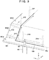
- Fig. 9 is a schematic view showing an example of a posture change.
- Discharge of the seal agent 100 can be either of, for example, a discontinuous discharge type that intermittently discharges a predetermined amount like an inkjet nozzle or a continuous discharge type that continuously discharges a predetermined amount.
- the tilt of the nozzle 21 is controlled such that, for example, the nozzle 21 is always in a state in which it stands in the normal direction of the surface of the work W1.
- application of the seal agent 100 by the nozzle 21 is performed along the seal application position Wp set on surfaces W1A, W1B, and W1C of the work W1.
- the application operation of the seal agent by the nozzle 21 is performed in a state in which the nozzle 21 is set apart from the work W1 by a predetermined distance so the nozzle 21 does not come into contact with the work W1.
- the nozzle 21 is set upright in a posture perpendicular to the surface W1A, like a nozzle 21A or 21B.
- the nozzle 21A or 21B in the upright state is moved in the Y direction.
- the seal agent 100 is thus applied to the surface W1A.
- application of the seal agent 100 to the surface W1B that is a tilted surface is performed.
- the nozzle 21A or 21B set upright is tilted to tilt its upper portion backward.
- the pivot mechanism 36 is driven to make the nozzle 21 pivot and tilt a nozzle 21C or 21D into a posture perpendicular to the surface W1B.
- the nozzle 21C or 21D in the tilted state is moved in the X direction.
- the seal agent 100 is thus applied to the surface W1B.
- the above-described posture control of the nozzle 21 is performed in real time in accordance with the tilt of the application surface of the seal agent 100 without stopping the movement of the nozzle 21.
- the seal agent 100 can be applied more evenly. For example, in a portion where the nozzle 21 is moved at a low speed, the discharge amount of the seal agent 100 is decreased. In a portion where the nozzle 21 is moved at a high speed, the discharge amount of the seal agent 100 is increased.
- the discharge amount of the seal agent 100 is controlled in accordance with the peripheral speed of the nozzle 21, thereby applying the seal agent 100 more evenly before and after the posture change of the operation unit 2.
- the moving speed of the distal end portion 21a of the nozzle 21 is calculated.
- the calculation of the distal end moving speed of the nozzle 21a is performed based on first moving speed information of the portion 21c of the nozzle 21 moved by the movable unit 31, the elevating unit 33, and the posture changing unit 34 and second moving speed information of the distal end portion 21a that moves about the portion 21c as the center.
- the calculated distal end moving speed information is transmitted to the control apparatus 9B via the interface unit 93A.
- the control apparatus 9B receives the distal end moving speed information via the interface unit 93B, and controls the discharge amount of the seal agent 100 based on the received distal end moving speed information.
- the discharge amount of the seal agent 100 the discharge amount is set in advance in correspondence with a predetermined distal end speed. Note that the distance between the seal application position Wp and the distal end portion 21a of the nozzle 21 is set and controlled to an optimum height depending on the viscosity, material, and the like of the seal agent 100.
- the process advances to a process of overlaying the work W2 on the work W1.
- the moving device 3 moves to a standby position set in advance and stands by.
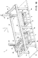
- Fig. 10 shows a process of holding the work W2 on the support device 5 by the holding unit 63.
- the holding unit 63 is temporarily lowered by the elevating unit 61 and holds the work W2.
- the work W2 is positioned with respect to the holding unit 63 by the plurality of positioning portions 633 and 634 and held in an appropriate posture.
- the holding unit 63 holds the work W2
- the holding unit 63 is raised by the elevating unit 61 to move the work W2 upward from the support device 5.
- the movable unit 60 is moved in the Y direction, as shown in Fig. 11 to convey the work W2 to a position on the upper side of the work W1.
- the holding unit 63 is lowered by the elevating unit 61 to overlay the work W2 on the work W1.
- the work W2 is thus bonded to the work W1 via the seal agent 100.
- the conveyance device 6 returns to the initial position (the position in Fig. 8 ).
- the works W1 and W2 bonded to each other are transferred by the transfer mechanisms 4a to the conveyance mechanism (not shown) outside the system. Similar processes are repeated from then on.
- the application operation of the seal agent 100 to the work W1, and the like can be performed in the above-described way.
- the moving device 3 that moves the operation unit 2 is configured to operate on the upper side of the work W1
- the occupation area of the operation system 1 substantially need only be slightly larger than the size of the work W1. It is therefore possible to make the occupation area of the system smaller than in a layout in which a vertical articulated robot is arranged on a lateral side of a work.
- the occupation area of the entire production system can be made small, and the factory can effectively be used.
- the movement of the operation unit 2 is translation in the X, Y, and Z directions, and in the initial posture, the axis ZA of the posture change of the operation unit 2 is coaxial to the nozzle 21, and the axis XA crosses the axis ZA on the nozzle 21. It is therefore possible to facilitate position control of the nozzle distal end portion with respect to the discharge position and application control according to the speed of the nozzle distal end portion as compared to a case of the combination of pivotal movements of a plurality of operation shafts as in the vertical articulated robot.
- the operation system concerning the operation of continuous application of the seal agent has been exemplified.
- the present invention is also applicable to an operation other than the application operation of the seal agent. That is, the present invention is applicable to an operation system including an operation unit including an operation portion that performs an operation for an operation point of a work or a posture changing unit that supports the operation unit.
- the operation portion is a solid or hollow shaft body. Examples are a nozzle (for example, a laser gun) that emits a laser beam to perform laser cutting or laser machining, a drill or a cutting tool used for chamfering or cutting, and a nozzle having a function of supplying a welding material to perform welding (for example, MIG welding or MAG welding).
Landscapes
- Engineering & Computer Science (AREA)
- Robotics (AREA)
- Mechanical Engineering (AREA)
- Coating Apparatus (AREA)
Abstract
Description
- The present invention relates to a technique of performing an operation for a work and, for example, to an application system configured to apply a seal agent.
- There is proposed a system that applies a seal agent to one of two members to be bonded to each other. For example, PTL 1 proposes a system capable of applying a seal agent along the three-dimensional shape of a work by discharging the seal agent from a nozzle while changing the posture of the work. In addition,
PTL -
- PTL 1: Japanese Patent No.
2866294 - PTL 2: Japanese Patent Laid-Open No.
2007-263599 - PTL 3: Japanese Patent Laid-Open No.
2006-122740 - In a case in which a relatively large work like a glass member that forms the windshield of an automobile is used as a work as a seal agent application target, if the posture of the work is changed, as in the system of PTL 1, an apparatus therefor has a large scale. The systems of
PTLs PTLs - It is an object of the present invention to improve the occupation area of a system and easiness of control.
- According to the present invention, there is provided an application system comprising:
- an application unit including a nozzle configured to discharge a seal agent to a work; and
- a moving device configured to move the application unit, wherein
- the moving device includes:
- a movable unit provided to be movable in a first horizontal direction along a guide portion extended in the first horizontal direction and including a support portion extending in a second horizontal direction orthogonal to the first horizontal direction;
- an elevating unit provided to be movable in the second horizontal direction with respect to the support portion; and
- a posture changing unit configured to be raised and lowered by the elevating unit and support the application unit,
- the application unit includes a supply portion configured to supply the seal agent to the nozzle,
- the nozzle includes a proximal end portion to which the seal agent is supplied from the supply portion, and a distal end portion configured to discharge the seal agent,
- the posture changing unit includes:
- a first pivot mechanism configured to make the application unit pivot about a vertical axis; and
- a second pivot mechanism configured to make the application unit pivot about a horizontal axis, and
- when the application unit is in a posture in which an axial direction of the nozzle faces a vertical direction,
- the vertical axis and the nozzle are located on the same axis, and
- the vertical axis and the horizontal axis cross on a center axis of the nozzle.
- According to the present invention, there is also provided an operation system comprising:
- an operation unit including an operation portion configured to perform an operation for an operation point of a work; and
- a moving device configured to move the operation unit, wherein
- the moving device includes:
- a movable unit provided to be movable in a first horizontal direction along a guide portion extended in the first horizontal direction and including a support portion extending in a second horizontal direction orthogonal to the first horizontal direction;
- an elevating unit provided to be movable in the second horizontal direction with respect to the support portion; and
- a posture changing unit configured to be raised and lowered by the elevating unit and support the operation unit,
- the operation portion is a solid or hollow shaft body,
- the posture changing unit includes:
- a first pivot mechanism configured to make the operation unit pivot about a vertical axis; and
- a second pivot mechanism configured to make the operation unit pivot about a horizontal axis, and
- when the operation unit is in a posture in which an operation shaft of the operation portion faces a vertical direction,
- the vertical axis and the operation portion are located on the same axis, and
- the vertical axis and the horizontal axis cross on a center axis of the operation portion.
- According to the present invention, there is also provided a posture changing unit provided to be movable in a vertical direction and at least one direction in a horizontal direction and configured to support an operation unit including an operation portion configured to perform an operation for an operation point of a work, wherein
the operation portion is a solid or hollow shaft body,
the posture changing unit includes: - a first pivot mechanism configured to make the operation unit pivot about a vertical axis; and
- a second pivot mechanism configured to make the operation unit pivot about a horizontal axis, and
- when the operation unit is in a posture in which an axial direction of the operation portion faces the vertical direction,
- the vertical axis and the operation portion are located on the same axis, and
- the vertical axis and the horizontal axis cross on a center axis of the operation portion.
- According to the present invention, it is possible to improve the occupation area of a system and easiness of control.
-
-
Fig. 1 is a schematic view of an operation system according to an embodiment of the present invention; -
Fig. 2 is a perspective view showing an example of works to be bonded; -
Fig. 3 is a perspective view of a posture changing unit and an operation unit; -
Fig. 4 shows a partially exploded perspective view of the posture changing unit and a perspective view of the operation unit; -
Fig. 5 is a perspective view of the posture changing unit, the operation unit, and a measuring unit; -
Fig. 6 is a perspective view of a holding unit; -
Fig. 7 is a view showing a positioning form of a work; -
Fig. 8 is an operation explanatory view of the operation system shown inFig. 1 ; -
Fig. 9 is an operation explanatory view showing an example of the movement and posture change of a nozzle; -
Fig. 10 is an operation explanatory view of the operation system shown inFig. 1 ; -
Fig. 11 is an operation explanatory view of the operation system shown inFig. 1 ; and -
Fig. 12 is a block diagram of the control apparatuses of the operation system shown inFig. 1 . -
Fig. 1 is a schematic view of an operation system 1 according to an embodiment of the present invention. The operation system 1 according to this embodiment is an application system configured to apply a seal agent to one of two works, overlay the work on the other work, and bond them.Fig. 2 is a perspective view showing an example of works as processing targets. A work W2 is an attachment body to be attached to a work W1 as a main body, and is a cover to be placed on the upper side of the work W1 in this embodiment. A plurality of positioning holes HI are formed in the work W1, and a plurality of positioning holes H2 are formed in the work W2 in correspondence with the positions of the holes HI. The operation system 1 endlessly applies aseal agent 100 along an operation position (seal application position) Wp set on the peripheral edge of the work W1. Theseal agent 100 is a kind of adhesive having a seal function. When the work W2 is overlaid from above on the work W1 with theseal agent 100 applied, they can be bonded. Note that in the drawings, arrows X and Y represent horizontal directions orthogonal to each other, and an arrow Z indicates a vertical direction. - Referring back to
Fig. 1 , the operation system 1 includes a plate-shapedbase member 10 that forms the frame of the operation system and defines the occupation area of the operation system 1. Thebase member 10 has a rectangular shape long in the Y direction. Thebase member 10 is provided with an installation portion where a plurality ofsupport columns 11 stand. In this embodiment, three lines ofsupport columns 11 are provided apart in the Y direction, and two lines ofsupport columns 11 are provided apart in the X direction. The installation portion is the peripheral edge region of thebase member 10. An almost half region on one end side of thebase member 10 in the Y direction, on which asupport device 4 is installed, is aninstallation portion 10a, and an almost half region on the other end side, on which asupport device 5 is installed, is aninstallation portion 10b. Theinstallation portion 10a is a region surrounded by a total of foursupport columns 11 including twosupport columns 11 at the center in the Y direction and twosupport columns 11 on the one end side. Theinstallation portion 10b is a region surrounded by a total of foursupport columns 11 including twosupport columns 11 at the center in the Y direction and twosupport columns 11 on the other end side. - The
support device 4 is a device configured to support the work W1. In this embodiment, the work W1 is supported via a pallet 8 (Fig. 7 or the like) to be described later. Thesupport device 4 includes a pair oftransfer mechanisms 4a, and aframe 4b that supports the pair oftransfer mechanisms 4a. The pair oftransfer mechanisms 4a are each extended in the X direction and arranged apart in the Y direction, and are mechanisms configured to convey thepallet 8 from one side to the other side in the X direction. The pair oftransfer mechanisms 4a are arranged while continuing to conveyance mechanisms (not shown) arranged on both sides of the operation system 1 in the X direction. The pallet 8 (on which the unprocessed work W1 is placed) transferred by the conveyance mechanisms and the pair oftransfer mechanisms 4a from the near side (one side) inFig. 1 is transferred in the X direction from the outside of the system 1 to the inside. After processing, the pallet 8 (on which the works W1 and W2 bonded to each other are placed) is transferred in the X direction (other side) to the outside of the system 1. Eachtransfer mechanism 4a is, for example, a belt conveyor or a roller conveyor. Thesupport device 4 is arranged under the moving range ofmovable units - The
support device 5 is a device configured to support the work W2. In this embodiment, the work W2 is supported via the pallet 8 (Fig. 7 or the like) to be described later. Thesupport device 5 has the same arrangement as that of thesupport device 4, and includes a pair oftransfer mechanisms 5a, and aframe 5b that supports the pair oftransfer mechanisms 5a. The pair oftransfer mechanisms 5a are each extended in the X direction and arranged apart in the Y direction, and are mechanisms configured to convey thepallet 8 from one side to the other side in the X direction. The pair oftransfer mechanisms 5a are arranged while continuing to conveyance mechanisms (not shown) arranged on both sides of the operation system 1 in the X direction. The pallet 8 (on which the work W2 is placed) transferred by the conveyance mechanisms and the pair oftransfer mechanisms 5a from the near side (one side) inFig. 1 is transferred from the outside of the system 1 to the inside. Eachtransfer mechanism 5a is, for example, a belt conveyor or a roller conveyor. Thesupport device 5 is arranged under the moving range of themovable unit 60 to be described later. - The operation system 1 includes a moving
device 3 that moves anoperation unit 2. The movingdevice 3 includes themovable unit 31, a pair of guide frames 32, an elevatingunit 33, and aposture changing unit 34. The pair of guide frames 32 function as a guide portion that guides the movement of themovable unit 31 in the Y direction. The pair of guide frames 32 are each extended in the Y direction and supported by thesupport columns 11 while being apart in the X direction. - The
movable unit 31 is a beam-shaped unit laid on the pair of guide frames 32. Themovable unit 31 includes asupport portion 31a extending in the X direction, and drivingportions 31b arranged at the two ends of thesupport portion 31a in the X direction.Fig. 1 shows only one drivingportion 31b. Each drivingportion 31b includes a motor as a driving source, and exhibits a traveling force with respect to the guide frames 32. As the transmission mechanism of the driving force of the motor, theguide frame 32 is provided with, for example, a rack or a ball screw shaft, and the drivingportion 31b includes a pinion meshed with the rack or a ball nut meshed with the ball screw shaft. When the two drivingportions 31b are synchronously driven and controlled, themovable unit 31 can translate in the Y direction by the guide of the pair of guide frames 32. - On the
support portion 31a, aslider 31c is provided to be movable in the X direction. Thesupport portion 31a functions as a guide frame that guides the movement of theslider 31c. Theslider 31c is provided with a driving portion 31d. The driving portion 31d includes a motor as a driving source, and theslider 31c travels along thesupport portion 31a. As the transmission mechanism of the driving force of the motor, thesupport portion 31a is provided with, for example, a rack or a ball screw shaft, and the driving portion 31d includes a pinion meshed with the rack or a ball nut meshed with the ball screw shaft. - Note that the
movable unit 31 is a beam-shaped unit in this embodiment but may be a gate-shaped unit. In this case, an arrangement corresponding to the pair of guide frames 32 is supported on thebase member 10 without using the plurality ofsupport columns 11. - The elevating
unit 33 is fixed to theslider 31c. When theslider 31c moves, the elevatingunit 33 is moved in the X direction along thesupport portion 31a. The elevatingunit 33 includes a drivingportion 33a. The drivingportion 33a includes a motor as a driving source. Theposture changing unit 34 and theoperation unit 2 are moved (raised and lowered) in the Z direction by the driving force of the motor. As the elevating mechanism, a ball screw mechanism or a rack-pinion mechanism can be employed. - With the above-described arrangement, the
operation unit 2 and theposture changing unit 34 can translate in the X, Y, and Z directions. Note that in this embodiment, theoperation unit 2 and theposture changing unit 34 are movable in two horizontal directions (X and Y). As for the horizontal direction, they may be movable only in the X direction or only in the Y direction in accordance with the purpose of an operation. - The
operation unit 2 and theposture changing unit 34 will be described with reference toFigs. 3 to 5 in addition toFig. 1 .Fig. 3 is a perspective view of theposture changing unit 34 and theoperation unit 2 supported by theposture changing unit 34.Fig. 4 shows a state in which acover 36d of theposture changing unit 34 is detached in the perspective view ofFig. 3 .Fig. 5 is a perspective view of theposture changing unit 34 and theoperation unit 2 viewed from a different line of sight, and also shows the outer appearance of a measuringunit 7. - The
operation unit 2 is an application unit that applies theseal agent 100 to the work W1. Theoperation unit 2 includes anozzle 21 that discharges theseal agent 100, and asupply portion 22 that supplies the seal agent 100 (seeFig. 2 ) to thenozzle 21. In addition, theoperation unit 2 includes an application control apparatus (acontrol apparatus 9B shown inFig. 12 ) that controls discharge of theseal agent 100 from thenozzle 21. Thenozzle 21 is an operation portion that performs an operation of discharging theseal agent 100. Thenozzle 21 is a hollow shaft body, and is a cylindrical tube including adistal end portion 21a and aproximal end portion 21b. Theproximal end portion 21b is connected to thesupply portion 22, and theseal agent 100 is supplied from thesupply portion 22. Theseal agent 100 pressure-fed by thesupply portion 22 to theproximal end portion 21b is discharged from the opening of thedistal end portion 21a. Thesupply portion 22 is connected to the supply source (not shown) of theseal agent 100 via a pipe. Thesupply portion 22 includes a storage portion that stores theseal agent 100, and a driving mechanism that pressure-feeds theseal agent 100 in the storage portion to thenozzle 21. - The
control apparatus 9B controls the start and stop of discharge of theseal agent 100 from thenozzle 21, and the discharge amount of theseal agent 100. In addition, thecontrol apparatus 9B communicates with acontrol apparatus 9A (Fig. 12 ) (to be described later) that controls the operations of the movingdevice 3 and theposture changing unit 34, and controls the discharge amount of theseal agent 100 in accordance with the moving speed of the distal end of thenozzle 21. When theoperation unit 2 includes the storage portion and thecontrol apparatus 9B, the influence of the temperature of the seal agent or a pressure change in a supply path to supply the seal agent can be prevented, and the discharge amount of theseal agent 100 can more accurately be controlled. As theoperation unit 2, a known application unit can be employed. - The measuring
unit 7 is a sensor configured to measure the application state of theseal agent 100 discharged from thenozzle 21. In this embodiment, the measuringunit 7 is a range finder that emits alaser beam 7a and measures reflected light. The irradiation destination of thelaser beam 7a is set on an almost extended line in the axial direction of thenozzle 21. When the shape (thickness, width, and the like) of theseal agent 100 discharged onto the work W1 is monitored by the measuringunit 7, it is possible to determine whether theseal agent 100 is appropriately applied or not, for example, whether a discharge error of theseal agent 100 has occurred or not. For example, as for the thickness, the height of the appliedseal agent 100 is monitored with reference to the seal application position Wp. Concerning the width, the width of the appliedseal agent 100 is monitored with reference to a preset installation value, thereby performing the determination. - The
posture changing unit 34 includes anupper frame 34a, alower frame 34c, and a connectingportion 34b that connects them such that they can pivot about an axis ZA in the Z direction. Theupper frame 34a is fixed to the lower end of the elevatingunit 33, and theposture changing unit 34, theoperation unit 2 and the measuringunit 7 are raised and lowered as a whole by the elevatingunit 33. - The
upper frame 34a is provided with apivot mechanism 35. Thepivot mechanism 35 is a mechanism configured to make thelower frame 34c pivot about the axis ZA with respect to theupper frame 34a, and includes amotor 35a that is a driving source, and atransmission mechanism 35b. Thetransmission mechanism 35a is, for example, a belt transmission mechanism, and includes a driving pulley to be driven by themotor 35a, and a driven pulley on the rotating shaft side, which is provided in the connectingportion 34b and fixed to thelower frame 34c. Thelower frame 34c is made to pivot about the axis ZA by driving themotor 35a. - The
lower frame 34c includes a plate-shapedhorizontal support member 34d, and a plate-shapedvertical support member 34e. The end of thehorizontal support member 34d on one side and the upper end of thevertical support member 34e are connected, and these members are combined in an inverted L shape. The connectingportion 34b (its rotating shaft) is connected to the center portion of thehorizontal support member 34d. The upper end of thevertical support member 34e is fixed to the end of thehorizontal support member 34d on one side and extended downward. The lower end of thevertical support member 34e is provided with a cylindricalpivotal support portion 34f extending in the horizontal direction, and asupport member 37 is connected via thepivotal support portion 34f. - The
support member 37 is a member that supports theoperation unit 2 and the measuringunit 7. Thesupport member 37 is located on the lower side of thelower frame 34c having the inverted L shape, and includes a fixedportion 37a to which a side portion of thesupply portion 22 of theoperation unit 2 is fixed, and a fixedportion 37b to which themeasuring unit 7 is fixed. The fixedportion 37a is a plate-shaped member, and the fixedportion 37b is a bracket attached to the plate-shaped member that forms the fixedportion 37a. A shaft-shaped connectingportion 37c extending in the horizontal direction is provided at the lower end of thesupport member 37. The connectingportion 37c is coaxially connected to thepivotal support portion 34f. Thesupport member 37 can pivot about an axis XA in the horizontal direction, which is the center axis of thepivotal support portion 34f and the connectingportion 37c. That is, theoperation unit 2, the measuringunit 7, and thesupport member 37 can integrally pivot about the axis XA. - The
vertical support member 34e is provided with apivot mechanism 36. Thepivot mechanism 36 is a mechanism that makes thesupport member 37 pivot about the axis ZX with respect to thelower frame 34c, and includes amotor 36a that is a driving source, atransmission mechanism 36e, atransmission mechanism 36b, and arotating shaft 36c. Themotor 36a is arranged on the other side surface (the surface on the lower side of thelower frame 34c having the inverted L shape) of thevertical support member 34e, and thetransmission mechanism 36b and therotating shaft 36c are arranged on one side surface of thevertical support member 34e. When the constituent elements of thepivot mechanism 36 are divisionally arranged on the two side surfaces of thevertical support member 34e, the installation space of thetransmission mechanism 36b can be made compact, and the support balance by weight distribution can be implemented. - The
transmission mechanism 36e is a relay transmission mechanism that transmits the driving force of themotor 36a to thetransmission mechanism 36b, and is formed on thevertical support member 34e. Thetransmission mechanism 36e includes atransmission element 36g (for example, a reduction gear) that is provided between themotor 36a and adriving gear 362 and transmits the driving force of themotor 36a at a predetermined ratio. Thetransmission element 36g includes a transmission input portion (not shown) connected to the output shaft of themotor 36a, a transmission output portion 36go to which thedriving gear 362 is connected, and a transmission attachment portion (not shown) attached to thevertical support member 34e. The transmission output portion 36go is rotatably attached to thevertical support member 34e via an opening formed in thevertical support member 34e. Therotating shaft 36c is a horizontal shaft fixed to the connectingportion 37c and is located at the lower end of thevertical support member 34e. - In this embodiment, the
transmission mechanism 36b is a rack-pinion mechanism including thedriving gear 362, arack 363, and drivengears driving gear 362 is meshed with therack 363. Therack 363 is a member with gear teeth arranged in the Z direction and is fixed to one side surface of a plate-shapedbracket 363a. The other side surface of thebracket 363a is provided with a plurality ofsliders 363b arranged apart in the Z direction. Arail member 363c extending in the Z direction is fixed to thevertical support member 34e. The plurality ofsliders 363b are engaged with therail member 363c and slid along therail member 363c. With these arrangements, therack 363 is supported by thevertical support member 34e to be movable in the Z direction. The pivotal movement of thedriving gear 362 caused by the driving of themotor 36a is transmitted to therack 363, and therack 363 is moved in the vertical direction. Note that thetransmission mechanism 36b is not limited to the rack-pinion mechanism, and may be a transmission mechanism of another type such as a belt transmission mechanism. - The driven
gear 361 is supported on the lower portion of thevertical support member 34e to be rotatable with respect to thevertical support member 34e, and is meshed with therack 363. When therack 363 rises or lowers, the drivengear 361 pivots. The drivengear 364 is fixed to an end of therotating shaft 36c and meshed with the drivengear 361. The drivengear 364 is connected to the connectingportion 37c via therotating shaft 36c. Hence, the rotation of thedriving gear 362 is transmitted to the drivengear 364 via therack 363 and the drivengear 361 and further transmitted to the connectingportion 37c via therotating shaft 36c. By this mechanism, when themotor 36a is made to pivot, thesupport member 37 can be made to pivot about the axis XA. In this embodiment, thesupport member 37 is made to pivot in a direction reverse to the pivotal movement of themotor 36a. - In this embodiment, the
pivotal support portion 34f is provided at the lower end of thevertical support member 34e to support the connectingportion 37c. On the other hand, themotor 36a is arranged on the upper side of the lower end of thevertical support member 34e, particularly, on the upper portion of thevertical support member 34e. In other words, themotor 36a is arranged at a position apart upward from thenozzle 21. This helps in preventing themotor 36a from interfering with the work W1 when theseal agent 100 is discharged from thenozzle 21 to the work W1. Themotor 36a is one of components with large sizes among the members that constitute the device, and is one of components whose interference with the work W1 should be taken into consideration. If themotor 36a is arranged near thenozzle 21, interference between themotor 36a and the work W1 occurs. It is therefore difficult to make thenozzle 21 approach the work W1 and discharge theseal agent 100. In this embodiment, thetransmission mechanism 36b is provided to keep themotor 36a apart from thenozzle 21. It is therefore possible to prevent themotor 36a and the work W1 from interfering with each other and make thenozzle 21 approach the work W1 and discharge theseal agent 100. - The periphery of the
transmission mechanism 36b is covered with thecover 36d, whereby sticking of foreign substances to thetransmission mechanism 36b is suppressed. Thecover 36d is fixed to thevertical support member 34e. - With the above-described arrangement, the
pivot mechanism 35 makes theoperation unit 2 pivot about the axis ZA, and thepivot mechanism 36 makes theoperation unit 2 pivot about the axis XA. It is therefore possible to change the direction of thenozzle 21, that is, the discharge direction of theseal agent 100 to an arbitrary direction. In this embodiment, since the measuringunit 7 is made to pivot integrally with theoperation unit 2 while maintaining the relative positional relationship to theoperation unit 2, it is possible to always stably measure the application state of theseal agent 100 without depending on the posture of theoperation unit 2. - The positional relationship between the axis ZA, the axis XA, and the
nozzle 21 will be described here with reference toFig. 5. Fig. 5 shows a case in which theoperation unit 2 is in an initial posture (or reference posture) in which the axial direction of thenozzle 21 is directed downward in the Z direction. In the initial posture, the center axis of thenozzle 21 and the axis ZA are located on the same axis. In addition, the axis ZA and the axis XA cross on aportion 21c of thenozzle 21. Here, since the distance between theportion 21c of thenozzle 21 and thedistal end portion 21a is known, the position of thedistal end portion 21a when the posture of theoperation unit 2 is changed can easily be obtained by calculation. For this reason, for example, even if the posture of theoperation unit 2 is changed, the distance between the position of thedistal end portion 21a and the seal application position Wp can be maintained at a distance at which the they do not interfere with each other, and the seal agent to be supplied can stably be supplied. As a result, application control of theseal agent 100 to the work W1 can relatively easily be performed. In addition, the discharge amount of theseal agent 100 is controlled in accordance with the moving speed (a speed obtained by adding the moving speed of theoperation unit 2 by the movingdevice 3 to the peripheral speed of thedistal end portion 21a about the axis XA) of thedistal end portion 21a in posture change (in particular, a posture change about the axis XA) of thenozzle 21. - In this embodiment, the
portion 21c is at a position apart from both thedistal end portion 21a and theproximal end portion 21b, and is located at the intermediate portion of thenozzle 21 in the axial direction. Theportion 21c that is the intersection between the axis ZA (the center axis of thenozzle 21 in the initial posture) and the axis XA is not limited to this embodiment, and may be located at, for example, thedistal end portion 21a. In this case, even if the posture of theoperation unit 2 is changed, and the posture of thenozzle 21 is changed, the position of thedistal end portion 21a of thenozzle 21 is always constant. It is therefore unnecessary to perform calculation and control of the application position of theseal agent 100 to the work W1. On the other hand, the distance between the work W1 and peripheral components such as thepivotal support portion 34f becomes short. For this reason, to avoid interference between the work W1 and the peripheral components, thedistal end portion 21a of thenozzle 21 cannot made to sufficiently approach the work W1. To avoid the interference with the work W1, theportion 21c is preferably a portion apart from thedistal end portion 21a to the side of theproximal end portion 21b. - The
portion 21c that is the intersection between the axis ZA and the axis XA may be located in theproximal end portion 21b. In this case, since the interference between the peripheral components and the work W1 is hardly problematic, thedistal end portion 21a of thenozzle 21 can be made to sufficiently approach the work W1. On the other hand, when changing the posture of theoperation unit 2, the change amount of the position of thedistal end portion 21a becomes large. For this reason, depending on the shape of the work W1, it may be difficult to continuously apply theseal agent 100 while moving theoperation unit 2. - In the view of the above-described points, locating the
portion 21c at the intermediate portion of thenozzle 21 in the axial direction, as in this embodiment, is well-balanced in terms of avoiding interference with the work W1 and continuously applying theseal agent 100. - Referring back to
Fig. 1 , the operation system 1 includes a conveyance device 6 configured to convey the work W2 from thesupport device 5 to thesupport device 4. The conveyance device 6 includes themovable unit 60, an elevatingunit 61, apivot unit 62, and a holdingunit 63. In this embodiment, the pair of guide frames 32 are also used as a guide portion that guides the movement of themovable unit 60 in the Y direction. However, a guide portion exclusive for themovable unit 60 may be provided. - The
movable unit 60 is a beam-shaped unit laid on the pair of guide frames 32. Drivingportions 60a are provided at the two ends of themovable unit 60 in the X direction. Each drivingportion 60a includes a motor as a driving source, and themovable unit 60 travels along the guide frames 32. When the two drivingportions 60a are synchronously driven and controlled, themovable unit 60 can translate in the Y direction by the guide of the pair of guide frames 32. - Note that the
movable unit 60 is a beam-shaped unit in this embodiment but may be a gate-shaped unit. - The elevating
unit 61 is provided at an arbitrary position (the center portion inFig. 1 ) of themovable unit 60 in the X direction, and raises and lowers thepivot unit 62. The elevatingunit 61 includes a drivingportion 61a. The drivingportion 61a includes a motor as a driving source, and moves (raises and lowers) thepivot unit 62 in the Z direction by the driving force of the motor. As the elevating mechanism, a ball screw mechanism or a rack-pinion mechanism can be employed. - The
pivot unit 62 is a columnar elevating body to be raised and lowered by the elevatingunit 61, and also includes, at its lower end, a mechanism (for example, a motor and a reduction gear) configured to make the holdingunit 63 pivot about the Z-axis. - The holding
unit 63 is a unit that is supported at the lower end of thepivot unit 62 and holds the work W2 on thesupport device 5. The holdingunit 63 is raised and lowered by driving the elevatingunit 61, and the direction of the holdingunit 63 on a plane orthogonal to the Z-axis can be corrected by driving thepivot unit 62. -
Fig. 6 is a perspective view of the holdingunit 63. The holdingunit 63 includes aframe 631 connected to the lower end of thepivot unit 62. A plurality of holdingportions 632 configured to hold the work W2 are supported by theframe 631. The holdingportions 632 suck the work W2 by, for example, suction of air. Theframe 631 is also provided with a plurality ofpositioning portions positioning portions 633 are shaft-shaped members, and are fitted in the positioning holes H2 of the work W2 to do positioning in the X and Y directions (positioning in the horizontal direction). The plurality ofpositioning portions 634 are rod-shaped members, and abut against the upper surface of the work W2 to do positioning upward in the Z direction. The plurality ofpositioning portions 634 have different lengths according to the heights between the abutment portion and theframe 631. -
Fig. 7 shows an example of the holding form of the work W2 by the holdingunit 63. The example ofFig. 7 shows a process of overlaying the work W2 on the work W1 supported on thesupport device 4 via thepallet 8. As shown inFig. 7 , when the plurality of holdingportions 632 suck the upper surface of the work W2, the work W2 is supported by the holdingunit 63. In addition, the positioningportions 633 are fitted in the holes H2 to maintain positioning in the X and Y directions. Furthermore, the distal ends of thepositioning portions 634 abut against the upper surface of the work W2 to maintain positioning in the Z direction. The upper surface of the work W2 has a three-dimensional shape. When the plurality ofpositioning portions 634 of different lengths abut, positioning in the Z direction can accurately be performed. - Note that the work W1 is positioned on the
pallet 8 as follows. That is, in thepallet 8, shaft-shapedpositioning portions 82 stand on aframe 81 that forms the main body. Thepositioning portions 82 are fitted in the positioning holes HI of the work W1, and positioning between thepallet 8 and the work W1 is thus done. Theframe 81 also includes anabutment portion 83 projecting sideward. A V-shaped notch is formed in theabutment portion 83. Thesupport device 4 is provided with apositioning portion 4c. Thepositioning portion 4c includes an abutment piece that abuts against the V-shaped notch of theabutment portion 83, and an actuator (for example, an air cylinder or an electric cylinder) configured to make the abutment piece enter in or retreat from the notch.Fig. 7 shows a state in which thepositioning portion 4c abuts against theabutment portion 83 to position thepallet 8 in the horizontal direction. Note that thesupport device 5 is also provided with a positioning portion (not shown) similar to thepositioning portion 4c. - The arrangement of the
control apparatus 9A and thecontrol apparatus 9B of the operation system 1 will be described next with reference toFig. 12 . In this embodiment, thecontrol apparatus 9A mainly controls the position and the posture of thenozzle 21 and thecontrol apparatus 9B mainly controls the discharge amount of the seal agent. However, an arrangement that performs these control operations by one control apparatus can also be employed. - The
control apparatus 9A includes aprocessing unit 91A such as a CPU, astorage unit 92A such as a RAM or a ROM, and aninterface unit 93A that interfaces an external device and theprocessing unit 91A. Theinterface unit 93A also includes a communication interface that performs communication with a host computer and communication with an interface unit 93B3 of thecontrol apparatus 9B. The host computer is, for example, a computer that controls management of a whole manufacturing facility in which the operation system 1 is arranged. - The
processing unit 91A executes a program stored in thestorage unit 92A, and controls various kinds ofactuators 94A that are output devices based on the detection results of various kinds ofsensors 95A that are input devices and an instruction of the host computer or the like. Thestorage unit 92A also stores information concerning application of the seal agent, such as coordinate information of the application path of theseal agent 100 corresponding to the type of the work as the processing target. The various kinds ofsensors 95A include, for example, the above-describedmeasuring unit 7, a sensor configured to detect the position of a movable component, and the like. The various kinds ofactuators 94A include the above-described various kinds of motors, and the like. - The
control apparatus 9B includes aprocessing unit 91B such as a CPU, astorage unit 92B such as a RAM or a ROM, and aninterface unit 93B that interfaces an external device and theprocessing unit 91B. Theinterface unit 93B also includes a communication interface that performs communication with thecontrol apparatus 9A. - The
processing unit 91B executes a program stored in thestorage unit 92B, and controls various kinds ofactuators 94B that are output devices based on the detection results of various kinds ofsensors 95B that are input devices and communication with thecontrol apparatus 9A. Thestorage unit 92B also stores information concerning application of the seal agent, such as a discharge amount corresponding to the type of the seal agent. The various kinds ofsensors 95B include, for example, sensors configured to detect the temperature around theoperation unit 2 and the amount of the suppliedseal agent 100, and the like. The various kinds ofactuators 94B include various kinds of actuators configured to control the discharge of the suppliedseal agent 100, and the like. - An example of the operation of the operation system 1 under the control of the
control apparatuses Figs. 8 to 11 .Fig. 8 shows a transfer operation of the works W1 and W2 into the system and an application operation of theapplication head 2. The works W1 and W2 are transferred to thesupport devices transfer mechanisms 4a of thesupport device 4 receive thepallet 8 with the work W1 placed on it and position thepallet 8. In addition, thetransfer mechanisms 5a of thesupport device 5 receive thepallet 8 with the work W2 placed on it and position thepallet 8. - When the work W1 is transferred onto the
support device 4, application of theseal agent 100 to the work W1 is performed by theoperation unit 2 and the movingdevice 3. The application operation is performed by, for example, discharging theseal agent 100 from thenozzle 21 while moving theoperation unit 2. Theoperation unit 2 is made to pivot about the axis ZA and the axis XA in correspondence with the shape of the work W1 while being moved in the X, Y, and Z directions by the movingdevice 3, thereby changing the posture.Fig. 9 is a schematic view showing an example of a posture change. Discharge of theseal agent 100 can be either of, for example, a discontinuous discharge type that intermittently discharges a predetermined amount like an inkjet nozzle or a continuous discharge type that continuously discharges a predetermined amount. - The tilt of the
nozzle 21 is controlled such that, for example, thenozzle 21 is always in a state in which it stands in the normal direction of the surface of the work W1. In the example ofFig. 9 , application of theseal agent 100 by thenozzle 21 is performed along the seal application position Wp set on surfaces W1A, W1B, and W1C of the work W1. Note that the application operation of the seal agent by thenozzle 21 is performed in a state in which thenozzle 21 is set apart from the work W1 by a predetermined distance so thenozzle 21 does not come into contact with the work W1. First, on the surface W1A, thenozzle 21 is set upright in a posture perpendicular to the surface W1A, like anozzle nozzle seal agent 100 is thus applied to the surface W1A. After completion of application to the surface W1A, application of theseal agent 100 to the surface W1B that is a tilted surface is performed. At this time, thenozzle pivot mechanism 36 is driven to make thenozzle 21 pivot and tilt anozzle nozzle seal agent 100 is thus applied to the surface W1B. After completion of application to the surface W1B, application to the surface W1C that is a planar portion is performed again. At this time, the tiltingnozzle nozzle 21 is set upright in a posture perpendicular to the surface W1C. Anozzle seal agent 100 to the surface W1C. - The above-described posture control of the
nozzle 21 is performed in real time in accordance with the tilt of the application surface of theseal agent 100 without stopping the movement of thenozzle 21. - At this time, when the discharge amount of the
seal agent 100 by theoperation unit 2 is controlled in accordance with the moving speed of thenozzle 21 by the movingdevice 3, theseal agent 100 can be applied more evenly. For example, in a portion where thenozzle 21 is moved at a low speed, the discharge amount of theseal agent 100 is decreased. In a portion where thenozzle 21 is moved at a high speed, the discharge amount of theseal agent 100 is increased. When making theoperation unit 2 pivot about the axis XA, the discharge amount of theseal agent 100 is controlled in accordance with the peripheral speed of thenozzle 21, thereby applying theseal agent 100 more evenly before and after the posture change of theoperation unit 2. - More specifically, during the process of performing movement control of the moving
device 3 and theposture changing unit 34 by thecontrol apparatus 9A, the moving speed of thedistal end portion 21a of thenozzle 21 is calculated. The calculation of the distal end moving speed of thenozzle 21a is performed based on first moving speed information of theportion 21c of thenozzle 21 moved by themovable unit 31, the elevatingunit 33, and theposture changing unit 34 and second moving speed information of thedistal end portion 21a that moves about theportion 21c as the center. The calculated distal end moving speed information is transmitted to thecontrol apparatus 9B via theinterface unit 93A. Thecontrol apparatus 9B receives the distal end moving speed information via theinterface unit 93B, and controls the discharge amount of theseal agent 100 based on the received distal end moving speed information. As for the discharge amount of theseal agent 100, the discharge amount is set in advance in correspondence with a predetermined distal end speed. Note that the distance between the seal application position Wp and thedistal end portion 21a of thenozzle 21 is set and controlled to an optimum height depending on the viscosity, material, and the like of theseal agent 100. - When the application of the
seal agent 100 to the work W1 is completed, the process advances to a process of overlaying the work W2 on the work W1. The movingdevice 3 moves to a standby position set in advance and stands by. -
Fig. 10 shows a process of holding the work W2 on thesupport device 5 by the holdingunit 63. The holdingunit 63 is temporarily lowered by the elevatingunit 61 and holds the work W2. At the time of holding, the work W2 is positioned with respect to the holdingunit 63 by the plurality ofpositioning portions unit 63 holds the work W2, the holdingunit 63 is raised by the elevatingunit 61 to move the work W2 upward from thesupport device 5. - Next, the
movable unit 60 is moved in the Y direction, as shown inFig. 11 to convey the work W2 to a position on the upper side of the work W1. The holdingunit 63 is lowered by the elevatingunit 61 to overlay the work W2 on the work W1. The work W2 is thus bonded to the work W1 via theseal agent 100. After that, the conveyance device 6 returns to the initial position (the position inFig. 8 ). The works W1 and W2 bonded to each other are transferred by thetransfer mechanisms 4a to the conveyance mechanism (not shown) outside the system. Similar processes are repeated from then on. - In this embodiment, the application operation of the
seal agent 100 to the work W1, and the like can be performed in the above-described way. Since the movingdevice 3 that moves theoperation unit 2 is configured to operate on the upper side of the work W1, the occupation area of the operation system 1 substantially need only be slightly larger than the size of the work W1. It is therefore possible to make the occupation area of the system smaller than in a layout in which a vertical articulated robot is arranged on a lateral side of a work. Particularly in a production system formed by arranging a plurality of operation systems configured to perform a plurality of operations, the occupation area of the entire production system can be made small, and the factory can effectively be used. In addition, the movement of theoperation unit 2 is translation in the X, Y, and Z directions, and in the initial posture, the axis ZA of the posture change of theoperation unit 2 is coaxial to thenozzle 21, and the axis XA crosses the axis ZA on thenozzle 21. It is therefore possible to facilitate position control of the nozzle distal end portion with respect to the discharge position and application control according to the speed of the nozzle distal end portion as compared to a case of the combination of pivotal movements of a plurality of operation shafts as in the vertical articulated robot. - In the above-described embodiment, the operation system concerning the operation of continuous application of the seal agent has been exemplified. However, the present invention is also applicable to an operation other than the application operation of the seal agent. That is, the present invention is applicable to an operation system including an operation unit including an operation portion that performs an operation for an operation point of a work or a posture changing unit that supports the operation unit. The operation portion is a solid or hollow shaft body. Examples are a nozzle (for example, a laser gun) that emits a laser beam to perform laser cutting or laser machining, a drill or a cutting tool used for chamfering or cutting, and a nozzle having a function of supplying a welding material to perform welding (for example, MIG welding or MAG welding).
- The present invention is not limited to the above embodiments, and various changes and modifications can be made within the spirit and scope of the present invention. Therefore, to apprise the public of the scope of the present invention, the following claims are made.
Claims (18)
- An application system comprising:an application unit including a nozzle configured to discharge a seal agent to a work; anda moving device configured to move the application unit, whereinthe moving device includes:a movable unit provided to be movable in a first horizontal direction along a guide portion extended in the first horizontal direction and including a support portion extending in a second horizontal direction orthogonal to the first horizontal direction;an elevating unit provided to be movable in the second horizontal direction with respect to the support portion; anda posture changing unit configured to be raised and lowered by the elevating unit and support the application unit,the application unit includes a supply portion configured to supply the seal agent to the nozzle,the nozzle includes a proximal end portion to which the seal agent is supplied from the supply portion, and a distal end portion configured to discharge the seal agent,the posture changing unit includes:a first pivot mechanism configured to make the application unit pivot about a vertical axis; anda second pivot mechanism configured to make the application unit pivot about a horizontal axis, andwhen the application unit is in a posture in which an axial direction of the nozzle faces a vertical direction,the vertical axis and the nozzle are located on the same axis, andthe vertical axis and the horizontal axis cross on a center axis of the nozzle.
- The application system according to claim 1, wherein
the posture changing unit further includes a support member configured to support the application unit, and
the support member includes:a first fixed portion to which the supply portion is fixed; anda connecting portion connected to the second pivot mechanism. - The application system according to claim 1, wherein
a portion on the center axis at which the vertical axis and the horizontal axis cross is a portion apart from the distal end portion to a side of the proximal end portion. - The application system according to claim 2, further comprising a measuring unit configured to measure an application state of the seal agent discharged from the nozzle,
wherein the support member further includes a second fixed portion to which the measuring unit is fixed. - The application system according to claim 1, further comprising a control apparatus configured to control the moving device,
wherein the control apparatus controls a position of the nozzle while changing a discharge direction of the nozzle along an application path of the seal agent to the work. - The application system according to claim 1, further comprising a control apparatus configured to control the application unit,
wherein the control apparatus controls a discharge amount of the seal agent by the application unit in accordance with a moving speed of the nozzle by the moving device. - The application system according to claim 1, wherein
the posture changing unit comprises a support member extended in the vertical direction,
the application unit is supported at a lower end of the support member to be able to pivot about the horizontal axis, and
the second pivot mechanism includes:a motor supported by the support member on an upper side of the lower end; anda transmission mechanism supported by the support member and configured to transmit a driving force of the motor to the application unit and make the application unit pivot about the horizontal axis. - The application system according to claim 7, wherein
the transmission mechanism includes:a driven gear connected to a pivot shaft of the application unit;a driving gear arranged on an upper side of the driven gear and driven by the driving force of the motor; anda rack configured to transmit rotation of the driving gear to the driven gear. - The application system according to claim 1, further comprising:a pair of frames serving as the guide portion, which are extended in the first horizontal direction and apart in the second horizontal direction;a plurality of support columns configured to support the pair of frames; anda support device configured to support the work,wherein the movable unit is laid on the pair of frames,the support device is arranged under a moving range of the movable unit, and includes a positioning portion configured to position the work,the application system further includes a base member configured to support the plurality of support columns and the support device, andthe base member includes an installation portion where the plurality of support columns are installed, and an installation portion where the support device is installed.
- The application system according to claim 9, wherein
the support device further includes a transfer mechanism configured to transfer the work between an outside and an inside of the application system. - The application system according to claim 9, further comprising a conveyance device configured to convey, on to a work supported by the support device, an attachment body to be attached to the work via the seal agent,
wherein the conveyance device includes:a second movable unit laid on the pair of frames and configured to move in the first horizontal direction;a second elevating unit supported by the second movable unit;a holding unit configured to hold the attachment body and raised and lowered by the second elevating unit; anda third pivot mechanism supported by the second elevating unit and configured to make the holding unit pivot about the vertical axis. - The application system according to claim 11, wherein
the holding unit includes a holding portion configured to hold the attachment body, and a positioning portion configured to position the held attachment body in the horizontal direction and the vertical direction. - The application system according to claim 11, wherein
the support device further includes a transfer mechanism configured to transfer the attachment body between an outside and an inside of the application system. - An operation system comprising:an operation unit including an operation portion configured to perform an operation for an operation point of a work; anda moving device configured to move the operation unit, whereinthe moving device includes:a movable unit provided to be movable in a first horizontal direction along a guide portion extended in the first horizontal direction and including a support portion extending in a second horizontal direction orthogonal to the first horizontal direction;an elevating unit provided to be movable in the second horizontal direction with respect to the support portion; anda posture changing unit configured to be raised and lowered by the elevating unit and support the operation unit,the operation portion is a solid or hollow shaft body,the posture changing unit includes:a first pivot mechanism configured to make the operation unit pivot about a vertical axis; anda second pivot mechanism configured to make the operation unit pivot about a horizontal axis, andwhen the operation unit is in a posture in which an operation shaft of the operation portion faces a vertical direction,the vertical axis and the operation portion are located on the same axis, andthe vertical axis and the horizontal axis cross on a center axis of the operation portion.
- A posture changing unit provided to be movable in a vertical direction and at least one direction in a horizontal direction and configured to support an operation unit including an operation portion configured to perform an operation for an operation point of a work, wherein
the operation portion is a solid or hollow shaft body,
the posture changing unit includes:a first pivot mechanism configured to make the operation unit pivot about a vertical axis; anda second pivot mechanism configured to make the operation unit pivot about a horizontal axis, andwhen the operation unit is in a posture in which an axial direction of the operation portion faces the vertical direction,the vertical axis and the operation portion are located on the same axis, andthe vertical axis and the horizontal axis cross on a center axis of the operation portion. - The posture changing unit according to claim 15, wherein
the posture changing unit further includes a support member configured to support the operation portion, and
the support member includes a connecting portion connected to the second pivot mechanism. - The posture changing unit according to claim 15, wherein
the posture changing unit comprises a support member extended in the vertical direction,
the operation unit is supported at a lower end of the support member to be able to pivot about the horizontal axis, and
the second pivot mechanism includes:a motor supported by the support member on an upper side of the lower end; anda transmission mechanism supported by the support member and configured to transmit a driving force of the motor to the operation unit and make the operation unit pivot about the horizontal axis. - The posture changing unit according to claim 17, wherein
the transmission mechanism includes:a driven gear connected to a pivot shaft of the operation unit;a driving gear arranged on an upper side of the driven gear and driven by the driving force of the motor; anda rack configured to transmit rotation of the driving gear to the driven gear.
Applications Claiming Priority (2)
| Application Number | Priority Date | Filing Date | Title |
|---|---|---|---|
| JP2018005055 | 2018-01-16 | ||
| PCT/JP2018/045842 WO2019142557A1 (en) | 2018-01-16 | 2018-12-13 | Application system, operation system, and attitude changing unit |
Publications (2)
| Publication Number | Publication Date |
|---|---|
| EP3656477A1 true EP3656477A1 (en) | 2020-05-27 |
| EP3656477A4 EP3656477A4 (en) | 2021-02-24 |
Family
ID=67301015
Family Applications (1)
| Application Number | Title | Priority Date | Filing Date |
|---|---|---|---|
| EP18901385.7A Withdrawn EP3656477A4 (en) | 2018-01-16 | 2018-12-13 | APPLICATION SYSTEM, OPERATING SYSTEM AND DIRECTION CHANGE UNIT |
Country Status (6)
| Country | Link |
|---|---|
| US (1) | US11167306B2 (en) |
| EP (1) | EP3656477A4 (en) |
| JP (1) | JP6960473B2 (en) |
| KR (1) | KR102335942B1 (en) |
| CN (1) | CN111032233B (en) |
| WO (1) | WO2019142557A1 (en) |
Cited By (1)
| Publication number | Priority date | Publication date | Assignee | Title |
|---|---|---|---|---|
| US12605684B2 (en) | 2019-08-19 | 2026-04-21 | Rampf Production Systems Gmbh & Co. Kg | Metering system |
Families Citing this family (8)
| Publication number | Priority date | Publication date | Assignee | Title |
|---|---|---|---|---|
| US11246249B2 (en) * | 2020-04-15 | 2022-02-08 | Illinois Tool Works Inc. | Tilt and rotate dispenser having strain wave gear system |
| JP7464453B2 (en) * | 2020-06-15 | 2024-04-09 | 株式会社Subaru | Coating Equipment |
| CN112439644B (en) * | 2020-11-12 | 2022-02-22 | 博众精工科技股份有限公司 | Assembling and glue dispensing device |
| CN113070191B (en) * | 2021-05-12 | 2021-09-28 | 广州信邦智能装备股份有限公司 | Automatic glue spreader for front windshield and rear windshield of automobile |
| CN113524128B (en) * | 2021-06-29 | 2022-08-12 | 中国空间技术研究院 | A low-orbit internet satellite payload module precision maintaining tooling |
| CN115430577B (en) * | 2022-09-29 | 2023-12-08 | 东莞盛翔精密金属有限公司 | Dispensing equipment |
| CN115555166B (en) * | 2022-11-10 | 2025-08-26 | 山东丰源汽车科技有限公司 | A continuous conveying coating oil spraying device for automobile transmission shaft |
| KR102876461B1 (en) * | 2024-06-25 | 2025-10-30 | 주식회사 제로원파트너스 | Manufacturing automation process system to prevent oxidation corrosion of steel structures in industrial plants |
Family Cites Families (36)
| Publication number | Priority date | Publication date | Assignee | Title |
|---|---|---|---|---|
| DE3738619A1 (en) * | 1987-11-13 | 1989-06-01 | Daimler Benz Ag | Deburring device for an industrial robot |
| US5520951A (en) | 1993-02-01 | 1996-05-28 | Canon Kabushiki Kaisha | Method for applying sealant to a toner container for an image forming apparatus |
| JP2866294B2 (en) | 1993-02-01 | 1999-03-08 | キヤノン株式会社 | Sealant application device, sealant application method, and toner container of image forming apparatus |
| JP3113212B2 (en) * | 1996-05-09 | 2000-11-27 | 富士通株式会社 | Plasma display panel phosphor layer forming apparatus and phosphor coating method |
| JP4109754B2 (en) * | 1998-06-24 | 2008-07-02 | 芝浦メカトロニクス株式会社 | Coating device and electronic component mounting device |
| JP2002239435A (en) * | 2001-02-16 | 2002-08-27 | Matsushita Electric Ind Co Ltd | Viscous material application device and viscous material application method |
| JP4251793B2 (en) * | 2001-07-27 | 2009-04-08 | 株式会社日立プラントテクノロジー | Paste applicator |
| KR100506642B1 (en) * | 2001-12-19 | 2005-08-05 | 마츠시타 덴끼 산교 가부시키가이샤 | Method and apparatus of forming pattern of display panel |
| JP3828816B2 (en) * | 2002-02-05 | 2006-10-04 | 株式会社 日立インダストリイズ | Liquid applicator |
| JP4273709B2 (en) * | 2002-06-19 | 2009-06-03 | セイコーエプソン株式会社 | Manufacturing method of optical member |
| KR100503113B1 (en) * | 2003-03-18 | 2005-07-22 | 지용식 | Ordinary our-face painting machine |
| JP4497468B2 (en) * | 2004-09-14 | 2010-07-07 | 株式会社不二越 | Sealing system |
| JP2006122740A (en) | 2004-10-26 | 2006-05-18 | Nissan Motor Co Ltd | Sealing device with coating amount inspection means |
| JP2007263599A (en) * | 2006-03-27 | 2007-10-11 | Mazda Motor Corp | Application state evaluation method and application state evaluation apparatus |
| US20090317554A1 (en) * | 2008-06-24 | 2009-12-24 | Specialty Coating Systems, Inc. | Apparatus and method for spray coating |
| JP5638768B2 (en) * | 2009-04-24 | 2014-12-10 | 武蔵エンジニアリング株式会社 | Nozzle rotation mechanism and coating apparatus having the same |
| TWM382891U (en) * | 2010-01-07 | 2010-06-21 | Everprec Tech Co Ltd | Angle adjustment structure of right-angle robot arm |
| US8066049B1 (en) * | 2010-07-22 | 2011-11-29 | Cheng Uei Precision Industry Co., Ltd. | Automatic gluing mechanism |
| US9433963B2 (en) * | 2012-11-06 | 2016-09-06 | Precision Valve & Automation, Inc. | Adhesive dispensing assembly having a mechanism for cleaning the dispensing nozzle |
| US8960123B2 (en) * | 2013-02-08 | 2015-02-24 | Enki Technology, Inc. | Coating and curing apparatus and methods |
| US10105725B2 (en) * | 2013-02-18 | 2018-10-23 | The Boeing Company | Fluid application device |
| US9475077B2 (en) * | 2013-03-28 | 2016-10-25 | Specialty Coating Systems, Inc. | High speed coating and dispensing apparatus |
| KR20150082913A (en) * | 2014-01-08 | 2015-07-16 | (주)버금시스템 | Apparatus for Hardening Unified Substrate and Controlling Method for the Same |
| JP6292092B2 (en) * | 2014-09-09 | 2018-03-14 | 株式会社安川電機 | Coating apparatus, coating robot, and coating method |
| CN104324855B (en) * | 2014-11-19 | 2016-05-25 | 苏州博众精工科技有限公司 | The device of glue position, a kind of control point and some glue amount |
| WO2016125751A1 (en) * | 2015-02-03 | 2016-08-11 | 本田技研工業株式会社 | Coating apparatus |
| CN105562294A (en) * | 2016-02-04 | 2016-05-11 | 苏州光宝科技股份有限公司 | Online full-automatic high-speed jet dispenser |
| CN205701169U (en) * | 2016-03-22 | 2016-11-23 | 苏州吉岛电极科技有限公司 | Automatic spraying machine |
| CN105797917B (en) * | 2016-05-20 | 2019-04-16 | 厦门力巨自动化科技有限公司 | Point glue adhering machine |
| CN205673148U (en) * | 2016-06-14 | 2016-11-09 | 嘉兴盛隆拉链制造有限公司 | Slider of zipper fastener point paint device |
| JP6656102B2 (en) | 2016-07-13 | 2020-03-04 | 株式会社エナテック | Coating device and coating method |
| CN206048979U (en) * | 2016-08-24 | 2017-03-29 | 深圳市策维科技有限公司 | A kind of fit body and the abutted equipment comprising which |
| CN206116371U (en) * | 2016-09-23 | 2017-04-19 | 苏州宏瑞达新能源装备有限公司 | Template machine is put to photovoltaic glass plate's four -axis |
| CN206104267U (en) * | 2016-10-09 | 2017-04-19 | 东莞新友智能科技有限公司 | A combination of dispensing and patch equipment |
| CN206601546U (en) * | 2017-03-30 | 2017-10-31 | 深圳市极而峰工业设备有限公司 | A kind of LCD frames laminating apparatus |
| CN209056192U (en) * | 2018-11-14 | 2019-07-02 | 苏州华工自动化技术有限公司 | A kind of notebook narrow border screen dispensing assembly equipment |
-
2018
- 2018-12-13 JP JP2019565765A patent/JP6960473B2/en active Active
- 2018-12-13 KR KR1020207003916A patent/KR102335942B1/en active Active
- 2018-12-13 CN CN201880052759.0A patent/CN111032233B/en active Active
- 2018-12-13 EP EP18901385.7A patent/EP3656477A4/en not_active Withdrawn
- 2018-12-13 WO PCT/JP2018/045842 patent/WO2019142557A1/en not_active Ceased
-
2020
- 2020-02-12 US US16/788,846 patent/US11167306B2/en active Active
Cited By (1)
| Publication number | Priority date | Publication date | Assignee | Title |
|---|---|---|---|---|
| US12605684B2 (en) | 2019-08-19 | 2026-04-21 | Rampf Production Systems Gmbh & Co. Kg | Metering system |
Also Published As
| Publication number | Publication date |
|---|---|
| JP6960473B2 (en) | 2021-11-05 |
| JPWO2019142557A1 (en) | 2020-09-03 |
| KR102335942B1 (en) | 2021-12-06 |
| CN111032233A (en) | 2020-04-17 |
| CN111032233B (en) | 2022-03-01 |
| WO2019142557A1 (en) | 2019-07-25 |
| US11167306B2 (en) | 2021-11-09 |
| KR20200028988A (en) | 2020-03-17 |
| US20200179972A1 (en) | 2020-06-11 |
| EP3656477A4 (en) | 2021-02-24 |
Similar Documents
| Publication | Publication Date | Title |
|---|---|---|
| US11167306B2 (en) | Application system, operation system, and posture changing unit | |
| JP5638768B2 (en) | Nozzle rotation mechanism and coating apparatus having the same | |
| KR101411448B1 (en) | Deformable gantry type working apparatus | |
| KR101441142B1 (en) | Method of adjusting nozzle clearance of liquid application device and liquid application device | |
| KR20200081360A (en) | Liquid material application device and application method | |
| TW201513762A (en) | Method and device for automatically adjusting dispensing unit of dispenser | |
| JP2015042436A (en) | Apparatus and method for moving a structure in a manufacturing environment | |
| CN108202259B (en) | Machine tool with assembled configuration with cantilevered tool | |
| CA2975769A1 (en) | Coating apparatus | |
| JP2014073571A (en) | Surface direct copying mechanism, and machining device and machining method with the same | |
| CN114602736A (en) | Dispensing machine and method thereof | |
| KR20130118195A (en) | Paste applying apparatus, paste applying method, and die bonder | |
| WO2020217737A1 (en) | Conveyance device | |
| WO2019075838A1 (en) | Double glue dispensing valve device | |
| US12415203B2 (en) | System and method for automatically applying a bead of sealant within a peripheral groove | |
| EP2806720B1 (en) | Printed board working apparatus | |
| WO2018131143A1 (en) | Mounted-object working device | |
| KR20100123591A (en) | Paste applying device and applying method | |
| TWI572570B (en) | Glass panel cutting apparatus having double controller | |
| JP6560146B2 (en) | Viscous material applicator | |
| CN214682645U (en) | An automatic visual glue dispenser | |
| JP2012232282A (en) | Liquid application device | |
| JP2002264049A (en) | Tabletop robot and tabletop robot line | |
| CN102145471A (en) | Chamfering device of hard fragile plate | |
| JPH04100676A (en) | Device and method for profile gas cutting |
Legal Events
| Date | Code | Title | Description |
|---|---|---|---|
| STAA | Information on the status of an ep patent application or granted ep patent |
Free format text: STATUS: THE INTERNATIONAL PUBLICATION HAS BEEN MADE |
|
| PUAI | Public reference made under article 153(3) epc to a published international application that has entered the european phase |
Free format text: ORIGINAL CODE: 0009012 |
|
| STAA | Information on the status of an ep patent application or granted ep patent |
Free format text: STATUS: REQUEST FOR EXAMINATION WAS MADE |
|
| 17P | Request for examination filed |
Effective date: 20200217 |
|
| AK | Designated contracting states |
Kind code of ref document: A1 Designated state(s): AL AT BE BG CH CY CZ DE DK EE ES FI FR GB GR HR HU IE IS IT LI LT LU LV MC MK MT NL NO PL PT RO RS SE SI SK SM TR |
|
| AX | Request for extension of the european patent |
Extension state: BA ME |
|
| A4 | Supplementary search report drawn up and despatched |
Effective date: 20210121 |
|
| RIC1 | Information provided on ipc code assigned before grant |
Ipc: B05C 11/00 20060101ALI20210115BHEP Ipc: B05C 5/02 20060101ALI20210115BHEP Ipc: B05C 13/02 20060101ALI20210115BHEP Ipc: B05B 13/04 20060101ALI20210115BHEP Ipc: B05C 5/00 20060101AFI20210115BHEP Ipc: B05C 11/10 20060101ALI20210115BHEP |
|
| DAV | Request for validation of the european patent (deleted) | ||
| DAX | Request for extension of the european patent (deleted) | ||
| STAA | Information on the status of an ep patent application or granted ep patent |
Free format text: STATUS: EXAMINATION IS IN PROGRESS |
|
| 17Q | First examination report despatched |
Effective date: 20231113 |
|
| GRAP | Despatch of communication of intention to grant a patent |
Free format text: ORIGINAL CODE: EPIDOSNIGR1 |
|
| STAA | Information on the status of an ep patent application or granted ep patent |
Free format text: STATUS: GRANT OF PATENT IS INTENDED |
|
| INTG | Intention to grant announced |
Effective date: 20250521 |
|
| STAA | Information on the status of an ep patent application or granted ep patent |
Free format text: STATUS: THE APPLICATION IS DEEMED TO BE WITHDRAWN |
|
| 18D | Application deemed to be withdrawn |
Effective date: 20250923 |