EP3656350A1 - Ophthalmic apparatus with corrective meridians having extended tolerance band by modifying refractive powers in uniform meridian distribution - Google Patents
Ophthalmic apparatus with corrective meridians having extended tolerance band by modifying refractive powers in uniform meridian distribution Download PDFInfo
- Publication number
- EP3656350A1 EP3656350A1 EP19219661.6A EP19219661A EP3656350A1 EP 3656350 A1 EP3656350 A1 EP 3656350A1 EP 19219661 A EP19219661 A EP 19219661A EP 3656350 A1 EP3656350 A1 EP 3656350A1
- Authority
- EP
- European Patent Office
- Prior art keywords
- meridian
- degrees
- meridians
- ophthalmic apparatus
- polynomial
- Prior art date
- Legal status (The legal status is an assumption and is not a legal conclusion. Google has not performed a legal analysis and makes no representation as to the accuracy of the status listed.)
- Granted
Links
Images







Classifications
-
- G—PHYSICS
- G02—OPTICS
- G02C—SPECTACLES; SUNGLASSES OR GOGGLES INSOFAR AS THEY HAVE THE SAME FEATURES AS SPECTACLES; CONTACT LENSES
- G02C7/00—Optical parts
- G02C7/02—Lenses; Lens systems ; Methods of designing lenses
- G02C7/06—Lenses; Lens systems ; Methods of designing lenses bifocal; multifocal ; progressive
- G02C7/061—Spectacle lenses with progressively varying focal power
-
- A—HUMAN NECESSITIES
- A61—MEDICAL OR VETERINARY SCIENCE; HYGIENE
- A61F—FILTERS IMPLANTABLE INTO BLOOD VESSELS; PROSTHESES; DEVICES PROVIDING PATENCY TO, OR PREVENTING COLLAPSING OF, TUBULAR STRUCTURES OF THE BODY, e.g. STENTS; ORTHOPAEDIC, NURSING OR CONTRACEPTIVE DEVICES; FOMENTATION; TREATMENT OR PROTECTION OF EYES OR EARS; BANDAGES, DRESSINGS OR ABSORBENT PADS; FIRST-AID KITS
- A61F2/00—Filters implantable into blood vessels; Prostheses, i.e. artificial substitutes or replacements for parts of the body; Appliances for connecting them with the body; Devices providing patency to, or preventing collapsing of, tubular structures of the body, e.g. stents
- A61F2/02—Prostheses implantable into the body
- A61F2/14—Eye parts, e.g. lenses or corneal implants; Artificial eyes
- A61F2/16—Intraocular lenses
- A61F2/1613—Intraocular lenses having special lens configurations, e.g. multipart lenses; having particular optical properties, e.g. pseudo-accommodative lenses, lenses having aberration corrections, diffractive lenses, lenses for variably absorbing electromagnetic radiation, lenses having variable focus
-
- A—HUMAN NECESSITIES
- A61—MEDICAL OR VETERINARY SCIENCE; HYGIENE
- A61F—FILTERS IMPLANTABLE INTO BLOOD VESSELS; PROSTHESES; DEVICES PROVIDING PATENCY TO, OR PREVENTING COLLAPSING OF, TUBULAR STRUCTURES OF THE BODY, e.g. STENTS; ORTHOPAEDIC, NURSING OR CONTRACEPTIVE DEVICES; FOMENTATION; TREATMENT OR PROTECTION OF EYES OR EARS; BANDAGES, DRESSINGS OR ABSORBENT PADS; FIRST-AID KITS
- A61F2/00—Filters implantable into blood vessels; Prostheses, i.e. artificial substitutes or replacements for parts of the body; Appliances for connecting them with the body; Devices providing patency to, or preventing collapsing of, tubular structures of the body, e.g. stents
- A61F2/02—Prostheses implantable into the body
- A61F2/14—Eye parts, e.g. lenses or corneal implants; Artificial eyes
- A61F2/16—Intraocular lenses
- A61F2/1613—Intraocular lenses having special lens configurations, e.g. multipart lenses; having particular optical properties, e.g. pseudo-accommodative lenses, lenses having aberration corrections, diffractive lenses, lenses for variably absorbing electromagnetic radiation, lenses having variable focus
- A61F2/1616—Pseudo-accommodative, e.g. multifocal or enabling monovision
- A61F2/1618—Multifocal lenses
-
- A—HUMAN NECESSITIES
- A61—MEDICAL OR VETERINARY SCIENCE; HYGIENE
- A61F—FILTERS IMPLANTABLE INTO BLOOD VESSELS; PROSTHESES; DEVICES PROVIDING PATENCY TO, OR PREVENTING COLLAPSING OF, TUBULAR STRUCTURES OF THE BODY, e.g. STENTS; ORTHOPAEDIC, NURSING OR CONTRACEPTIVE DEVICES; FOMENTATION; TREATMENT OR PROTECTION OF EYES OR EARS; BANDAGES, DRESSINGS OR ABSORBENT PADS; FIRST-AID KITS
- A61F2/00—Filters implantable into blood vessels; Prostheses, i.e. artificial substitutes or replacements for parts of the body; Appliances for connecting them with the body; Devices providing patency to, or preventing collapsing of, tubular structures of the body, e.g. stents
- A61F2/02—Prostheses implantable into the body
- A61F2/14—Eye parts, e.g. lenses or corneal implants; Artificial eyes
- A61F2/16—Intraocular lenses
- A61F2/1613—Intraocular lenses having special lens configurations, e.g. multipart lenses; having particular optical properties, e.g. pseudo-accommodative lenses, lenses having aberration corrections, diffractive lenses, lenses for variably absorbing electromagnetic radiation, lenses having variable focus
- A61F2/1637—Correcting aberrations caused by inhomogeneities; correcting intrinsic aberrations, e.g. of the cornea, of the surface of the natural lens, aspheric, cylindrical, toric lenses
- A61F2/164—Aspheric lenses
-
- A—HUMAN NECESSITIES
- A61—MEDICAL OR VETERINARY SCIENCE; HYGIENE
- A61F—FILTERS IMPLANTABLE INTO BLOOD VESSELS; PROSTHESES; DEVICES PROVIDING PATENCY TO, OR PREVENTING COLLAPSING OF, TUBULAR STRUCTURES OF THE BODY, e.g. STENTS; ORTHOPAEDIC, NURSING OR CONTRACEPTIVE DEVICES; FOMENTATION; TREATMENT OR PROTECTION OF EYES OR EARS; BANDAGES, DRESSINGS OR ABSORBENT PADS; FIRST-AID KITS
- A61F2/00—Filters implantable into blood vessels; Prostheses, i.e. artificial substitutes or replacements for parts of the body; Appliances for connecting them with the body; Devices providing patency to, or preventing collapsing of, tubular structures of the body, e.g. stents
- A61F2/02—Prostheses implantable into the body
- A61F2/14—Eye parts, e.g. lenses or corneal implants; Artificial eyes
- A61F2/16—Intraocular lenses
- A61F2/1613—Intraocular lenses having special lens configurations, e.g. multipart lenses; having particular optical properties, e.g. pseudo-accommodative lenses, lenses having aberration corrections, diffractive lenses, lenses for variably absorbing electromagnetic radiation, lenses having variable focus
- A61F2/1637—Correcting aberrations caused by inhomogeneities; correcting intrinsic aberrations, e.g. of the cornea, of the surface of the natural lens, aspheric, cylindrical, toric lenses
- A61F2/1645—Toric lenses
-
- A—HUMAN NECESSITIES
- A61—MEDICAL OR VETERINARY SCIENCE; HYGIENE
- A61F—FILTERS IMPLANTABLE INTO BLOOD VESSELS; PROSTHESES; DEVICES PROVIDING PATENCY TO, OR PREVENTING COLLAPSING OF, TUBULAR STRUCTURES OF THE BODY, e.g. STENTS; ORTHOPAEDIC, NURSING OR CONTRACEPTIVE DEVICES; FOMENTATION; TREATMENT OR PROTECTION OF EYES OR EARS; BANDAGES, DRESSINGS OR ABSORBENT PADS; FIRST-AID KITS
- A61F2/00—Filters implantable into blood vessels; Prostheses, i.e. artificial substitutes or replacements for parts of the body; Appliances for connecting them with the body; Devices providing patency to, or preventing collapsing of, tubular structures of the body, e.g. stents
- A61F2/02—Prostheses implantable into the body
- A61F2/14—Eye parts, e.g. lenses or corneal implants; Artificial eyes
- A61F2/16—Intraocular lenses
- A61F2/1613—Intraocular lenses having special lens configurations, e.g. multipart lenses; having particular optical properties, e.g. pseudo-accommodative lenses, lenses having aberration corrections, diffractive lenses, lenses for variably absorbing electromagnetic radiation, lenses having variable focus
- A61F2/1654—Diffractive lenses
-
- G—PHYSICS
- G02—OPTICS
- G02C—SPECTACLES; SUNGLASSES OR GOGGLES INSOFAR AS THEY HAVE THE SAME FEATURES AS SPECTACLES; CONTACT LENSES
- G02C7/00—Optical parts
- G02C7/02—Lenses; Lens systems ; Methods of designing lenses
- G02C7/021—Lenses; Lens systems ; Methods of designing lenses with pattern for identification or with cosmetic or therapeutic effects
-
- G—PHYSICS
- G02—OPTICS
- G02C—SPECTACLES; SUNGLASSES OR GOGGLES INSOFAR AS THEY HAVE THE SAME FEATURES AS SPECTACLES; CONTACT LENSES
- G02C7/00—Optical parts
- G02C7/02—Lenses; Lens systems ; Methods of designing lenses
- G02C7/024—Methods of designing ophthalmic lenses
- G02C7/028—Special mathematical design techniques
-
- G—PHYSICS
- G02—OPTICS
- G02C—SPECTACLES; SUNGLASSES OR GOGGLES INSOFAR AS THEY HAVE THE SAME FEATURES AS SPECTACLES; CONTACT LENSES
- G02C7/00—Optical parts
- G02C7/02—Lenses; Lens systems ; Methods of designing lenses
- G02C7/04—Contact lenses for the eyes
- G02C7/041—Contact lenses for the eyes bifocal; multifocal
-
- G—PHYSICS
- G02—OPTICS
- G02C—SPECTACLES; SUNGLASSES OR GOGGLES INSOFAR AS THEY HAVE THE SAME FEATURES AS SPECTACLES; CONTACT LENSES
- G02C7/00—Optical parts
- G02C7/02—Lenses; Lens systems ; Methods of designing lenses
- G02C7/04—Contact lenses for the eyes
- G02C7/041—Contact lenses for the eyes bifocal; multifocal
- G02C7/042—Simultaneous type
-
- G—PHYSICS
- G02—OPTICS
- G02C—SPECTACLES; SUNGLASSES OR GOGGLES INSOFAR AS THEY HAVE THE SAME FEATURES AS SPECTACLES; CONTACT LENSES
- G02C7/00—Optical parts
- G02C7/02—Lenses; Lens systems ; Methods of designing lenses
- G02C7/04—Contact lenses for the eyes
- G02C7/041—Contact lenses for the eyes bifocal; multifocal
- G02C7/044—Annular configuration, e.g. pupil tuned
-
- G—PHYSICS
- G02—OPTICS
- G02C—SPECTACLES; SUNGLASSES OR GOGGLES INSOFAR AS THEY HAVE THE SAME FEATURES AS SPECTACLES; CONTACT LENSES
- G02C7/00—Optical parts
- G02C7/02—Lenses; Lens systems ; Methods of designing lenses
- G02C7/06—Lenses; Lens systems ; Methods of designing lenses bifocal; multifocal ; progressive
-
- A—HUMAN NECESSITIES
- A61—MEDICAL OR VETERINARY SCIENCE; HYGIENE
- A61F—FILTERS IMPLANTABLE INTO BLOOD VESSELS; PROSTHESES; DEVICES PROVIDING PATENCY TO, OR PREVENTING COLLAPSING OF, TUBULAR STRUCTURES OF THE BODY, e.g. STENTS; ORTHOPAEDIC, NURSING OR CONTRACEPTIVE DEVICES; FOMENTATION; TREATMENT OR PROTECTION OF EYES OR EARS; BANDAGES, DRESSINGS OR ABSORBENT PADS; FIRST-AID KITS
- A61F2/00—Filters implantable into blood vessels; Prostheses, i.e. artificial substitutes or replacements for parts of the body; Appliances for connecting them with the body; Devices providing patency to, or preventing collapsing of, tubular structures of the body, e.g. stents
- A61F2/02—Prostheses implantable into the body
- A61F2/14—Eye parts, e.g. lenses or corneal implants; Artificial eyes
- A61F2/16—Intraocular lenses
- A61F2/1613—Intraocular lenses having special lens configurations, e.g. multipart lenses; having particular optical properties, e.g. pseudo-accommodative lenses, lenses having aberration corrections, diffractive lenses, lenses for variably absorbing electromagnetic radiation, lenses having variable focus
- A61F2/1637—Correcting aberrations caused by inhomogeneities; correcting intrinsic aberrations, e.g. of the cornea, of the surface of the natural lens, aspheric, cylindrical, toric lenses
- A61F2/1643—Cylindrical lenses
-
- A—HUMAN NECESSITIES
- A61—MEDICAL OR VETERINARY SCIENCE; HYGIENE
- A61F—FILTERS IMPLANTABLE INTO BLOOD VESSELS; PROSTHESES; DEVICES PROVIDING PATENCY TO, OR PREVENTING COLLAPSING OF, TUBULAR STRUCTURES OF THE BODY, e.g. STENTS; ORTHOPAEDIC, NURSING OR CONTRACEPTIVE DEVICES; FOMENTATION; TREATMENT OR PROTECTION OF EYES OR EARS; BANDAGES, DRESSINGS OR ABSORBENT PADS; FIRST-AID KITS
- A61F2240/00—Manufacturing or designing of prostheses classified in groups A61F2/00 - A61F2/26 or A61F2/82 or A61F9/00 or A61F11/00 or subgroups thereof
- A61F2240/001—Designing or manufacturing processes
- A61F2240/002—Designing or making customized prostheses
-
- A—HUMAN NECESSITIES
- A61—MEDICAL OR VETERINARY SCIENCE; HYGIENE
- A61F—FILTERS IMPLANTABLE INTO BLOOD VESSELS; PROSTHESES; DEVICES PROVIDING PATENCY TO, OR PREVENTING COLLAPSING OF, TUBULAR STRUCTURES OF THE BODY, e.g. STENTS; ORTHOPAEDIC, NURSING OR CONTRACEPTIVE DEVICES; FOMENTATION; TREATMENT OR PROTECTION OF EYES OR EARS; BANDAGES, DRESSINGS OR ABSORBENT PADS; FIRST-AID KITS
- A61F2250/00—Special features of prostheses classified in groups A61F2/00 - A61F2/26 or A61F2/82 or A61F9/00 or A61F11/00 or subgroups thereof
- A61F2250/0058—Additional features; Implant or prostheses properties not otherwise provided for
- A61F2250/0096—Markers and sensors for detecting a position or changes of a position of an implant, e.g. RF sensors, ultrasound markers
- A61F2250/0097—Visible markings, e.g. indicia
-
- G—PHYSICS
- G02—OPTICS
- G02C—SPECTACLES; SUNGLASSES OR GOGGLES INSOFAR AS THEY HAVE THE SAME FEATURES AS SPECTACLES; CONTACT LENSES
- G02C2202/00—Generic optical aspects applicable to one or more of the subgroups of G02C7/00
- G02C2202/02—Mislocation tolerant lenses or lens systems
-
- G—PHYSICS
- G02—OPTICS
- G02C—SPECTACLES; SUNGLASSES OR GOGGLES INSOFAR AS THEY HAVE THE SAME FEATURES AS SPECTACLES; CONTACT LENSES
- G02C2202/00—Generic optical aspects applicable to one or more of the subgroups of G02C7/00
- G02C2202/06—Special ophthalmologic or optometric aspects
-
- G—PHYSICS
- G02—OPTICS
- G02C—SPECTACLES; SUNGLASSES OR GOGGLES INSOFAR AS THEY HAVE THE SAME FEATURES AS SPECTACLES; CONTACT LENSES
- G02C2202/00—Generic optical aspects applicable to one or more of the subgroups of G02C7/00
- G02C2202/10—Optical elements and systems for visual disorders other than refractive errors, low vision
-
- G—PHYSICS
- G02—OPTICS
- G02C—SPECTACLES; SUNGLASSES OR GOGGLES INSOFAR AS THEY HAVE THE SAME FEATURES AS SPECTACLES; CONTACT LENSES
- G02C2202/00—Generic optical aspects applicable to one or more of the subgroups of G02C7/00
- G02C2202/20—Diffractive and Fresnel lenses or lens portions
-
- G—PHYSICS
- G02—OPTICS
- G02C—SPECTACLES; SUNGLASSES OR GOGGLES INSOFAR AS THEY HAVE THE SAME FEATURES AS SPECTACLES; CONTACT LENSES
- G02C2202/00—Generic optical aspects applicable to one or more of the subgroups of G02C7/00
- G02C2202/22—Correction of higher order and chromatic aberrations, wave front measurement and calculation
Definitions
- an ophthalmic apparatus having regions of one or more base spherical powers and one or more cylinder powers that are added to the one or more base spherical power for correcting an astigmatism (e.g., an intended astigmatism).
- an astigmatism e.g., an intended astigmatism
- the meridians are uniformly arranged on the optical zones at about 0.3D (diopters). In some embodiments, the meridians are uniformly arranged on the optical zones at about 0.35D (diopters). In some embodiments, the meridians are uniformly arranged on the optical zones at about 0.4D (diopters). In some embodiments, the meridians are uniformly arranged on the optical zones at about 0.45D (diopters). In some embodiments, the meridians are uniformly arranged on the optical zones at about 0.5D (diopters). In some embodiments, the meridians are uniformly arranged on the optical zones at about 0.55D (diopters).
- the meridians are uniformly arranged on the optical zones at about 0.6D (diopters). In some embodiments, the meridians are uniformly arranged on the optical zones at about 0.65D (diopters). In some embodiments, the meridians are uniformly arranged on the optical zones at about 0.7D (diopters). In some embodiments, the meridians are uniformly arranged on the optical zones at about 0.75D (diopters). In some embodiments, the meridians are uniformly arranged on the optical zones at about 0.8D (diopters). In some embodiments, the meridians are uniformly arranged on the optical zones at about 0.85D (diopters). In some embodiments, the meridians are uniformly arranged on the optical zones at about 0.95D (diopters). In some embodiments, the meridians are uniformly arranged on the optical zones at about 1.0D (diopters).
- the polynomial-based surface is characterized by a series of weighted cosine-based function.
- the polynomial-bases surface at a first meridian comprises an extended range lens.
- the multi-zonal lens body forms a second angularly-varying phase member having a second peak cylinder power centered at a second correcting meridian, the second angularly-varying phase member at the second peak cylinder power being configured to direct light to a second point of focus on the retina.
- the second angularly-varying phase member varies, at each optical zone, along meridians nearby to the second correcting meridian to direct light to points of focus nearby to the second point of focus such the multi-zonal lens body, when rotational offset from the second peak cylinder power, directs light from the nearby points of focus to the second point of focus, and the second angularly-varying phase member has the profile that is uniformly spaced for every 0.5D (diopters).
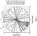
- Fig. 1 is a diagram of cylindrical map of a polynomial surface 102 (also referred to as an ETA polynomial surface 102) that is uniformly arranged over a plurality of meridians that provides extended rotational tolerance, in accordance with an illustrative embodiment.
- the polynomial surface 102 is mapped to a surface of an ophthalmic apparatus 100 (not shown - see Fig.
- CAM cylindrical axis misalignment
- VA visual acuity
- MTF modular transfer function
- the polynomial surface 102 is uniformly arranged over a plurality of meridians 106 for every 0.46D (diopters). In some embodiments, the polynomial surface 102 is uniformly arranged over a plurality of meridians 106 for every 0.45D (diopters). In some embodiments, the polynomial surface 102 is uniformly arranged over a plurality of meridians 106 for every 0.48D (diopters). In some embodiments, the polynomial surface 102 is uniformly arranged over a plurality of meridians 106 for every 0.52D (diopters).
- the meridians when the meridians are uniformly arranged for a same added power of 0.25D, for a 4D base, there are 16 meridians between the high power meridian and the lower power. This allows up to 6 corrective regions of the polynomial surface.
- the meridians when the meridians are uniformly arranged for a same added power of 1.0, for a 4D base, there are 2 meridians between the high power meridian and the lower power. This allows up to 3 corrective regions of the polynomial surface, which has the high power meridian center located at meridians 106e, 106s, and 106cc.
- Fig. 3 is a profile 300 of the polynomial surface of Fig. 1 with the plurality of uniformly arranged meridians, in accordance with an illustrative embodiment.
- each meridian e.g., 106b, 106c, 106d, 106e, 106f
- 106b, 106c, 106d, 106e, 106f is defined by an angular position that is uniformly arranged, about 11 degrees apart, for every 0.5D (diopters).
- the majority of meridian power change from one meridian to the next, generates a change of more than 0.6D power difference (shown as 304).
- the meridian (in degrees) from the minimum power meridian - namely 0 degrees (308a) - is located at a 20.7-degree position (308b), a 30-degree position (308c), a 37.8-degree position (308d), a 45.0-degree position (308e), a 52.2-degree position (308f), a 60-degree position (308g), a 69.3-degree position (308h), a 90.0-degree positon (308i), and etc., in a periodic trend, which provides a non-uniform meridian difference of about 20.7 degrees (between 308a and 308b), about 9.3 degrees (between 308b and 308c), about 7.8 degrees (between 308c and 308d), about 7.2 degrees (between 308d and 308e), about 7.2 degrees (between 308e and 308f), about 7.8 degree (between 308f and 308g), about 9.3 (between 308g and 308h), and about 20.7 degree (
- off-center structures of the polynomial surface 102 extend from the center structure in a gradually varying manner to apply cylinder power to a band of meridians surrounding the corrective meridian enabling the ophthalmic apparatus to operate off-axis (or off-meridian) to the corrective meridian (e.g., the astigmatism meridian).
- the corrective meridian e.g., the astigmatism meridian
- the polynomial surface 102 is defined by a combination of spline or polynomial (e.g., a Zernike polynomial, a Chebyshev polynomial, or a combination of both) that is constrained by the condition of the meridians being uniformly arranged apart for every 0.5D (diopters).
- spline or polynomial e.g., a Zernike polynomial, a Chebyshev polynomial, or a combination of both
- the polynomial surface 102 facilitates an extended band of the corrective meridian that has minimal, and/or clinically acceptable, degradation of the visual acuity and modulation transfer function when the ophthalmic apparatus is subjected to rotational misalignment between the astigmatic axis and a center axis of the corrective meridian.
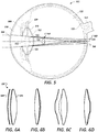
- Fig. 5 is a schematic drawing of a top view of a human eye 502, in which the natural lens of the eye 502 has been removed and replaced with an intraocular lens 100 (shown in simplified form in Fig. 6 and in greater detail in Figs. 6A, 6B, 6C, and 6D ).
- an intraocular lens 100 shown in simplified form in Fig. 6 and in greater detail in Figs. 6A, 6B, 6C, and 6D ).
- Light enters from the left of FIG. 5 , and passes through the cornea 504, the anterior chamber 506, the iris 508, and enters the capsular bag 510.
- the natural lens occupies essentially the entire interior of the capsular bag 510.
- the capsular bag 510 houses the intraocular lens 100, in addition to a fluid that occupies the remaining volume and equalizes the pressure in the eye.
- the optic 524 has an anterior surface 534 and a posterior surface 536, each having a particular shape that contributes to the refractive or diffractive properties of the lens. Either or both of these lens surfaces may optionally have an element made integral with or attached to the surfaces.
- Figs. 6A, 6B, 6C, and 6D are schematic diagrams of exemplary ophthalmic apparatuses that include the freeform-polynomial surface area 102, in accordance with an illustrative embodiment. Specifically, Figs. 6A and 6B show examples of diffractive lenses, and Figs. 6C and 6D show examples of refractive lenses.
- the intraocular lens 100 includes polynomial surface 102 (as a refractive, diffractive, or both) that focus at a plurality of focus points that are offset radially to one another so as to provide an extended tolerance to misalignments of the lens 100 when implanted into the eye 502. That is, when the center axis of a corrective meridian is exactly matched to the desired astigmatic axis, only a first portion of the cylinder axis is focused at the desired point of focus (338) (e.g., at the retina) while second portions of the cylinder axis focuses at other points (540) nearby that are radially offset to the desired point of focus (538).
- polynomial surface 102 as a refractive, diffractive, or both
- Artificial lenses can correct for certain visual impairments such as an inability of the natural lens to focus at near, intermediate or far distances; and/or astigmatism.
- Intraocular toric lenses have the potential for correcting astigmatism while also correcting for other vision impairments such as cataract, presbyopia, etc.
- implanted intraocular toric lenses may not adequately correct astigmatism due to rotational misalignment of the corrective meridian of the lenses with the astigmatic meridian.
- the corrective meridian of the implanted toric lenses can be rotationally misaligned to the astigmatic meridian, in some instances, by as much as 10 degrees.
- toric lenses that are designed to provide maximum correction (e.g., 1D to 9D) at the astigmatic meridian are subject to significant reduction in effectiveness of the correction due to any misalignment from the corrective meridian.
- Figs. 7 and 8 include plots that illustrate the above-discussed degraded performance of conventional toric lens when subjected to rotational misalignments.
- This conventional toric lens is configured to provide 6.00 Diopters cylinder powers at the IOL plane, 4.11 Diopters cylinder power at the corneal plane, and a corneal astigmatism correction range (i.e., preoperative corneal astigmatism to predicted effects) between 4.00 and 4.75 Diopters.
- a plot of the undesired meridian power (also referred to as a residual meridian power ("OC")) (shown along the y-axis) added due to the rotational misalignments (shown along the x-axis) of the toric IOL is shown, including the residual powers for i) a negative 10-degree misalignment (shown as line 702), ii) a 0-degree misalignment (shown as line 704), and iii) a positive 10-degree misalignment (shown as line 706).
- a negative 10-degree misalignment shown as line 702
- ii) a 0-degree misalignment shown as line 704
- iii) a positive 10-degree misalignment shown as line 706.
- ⁇ is the correction meridian (also referred to as the cylindrical power axis) (in degrees); C is the astigmatic power (at the IOL plane) to be corrected at meridian ⁇ (in Diopters); and ⁇ is the magnitude of rotational misalignment of the cylindrical power axis to the astigmatic axis (in degrees).
- Figs. 11A and 11B each shows calculated MTF values as spatial frequencies of an exemplified IOL 100 in a physiological eye model with astigmatic cornea in different cylindrical axis misalignment (CAM) situations between the cornea and the IOL for an iris pupil.
- the modulation transfer function MTF is maintained across the extended range of alignment for a lens configured with the freeform-polynomial surface area 102 of Fig. 1 .
- CAM cylindrical axis misalignment
- CAM 0 Deg
- CAM 5 Deg
- CAM 10 Deg
- Fig. 11A the iris pupil is about 3.0mm.
- Fig. 11B the iris pupil is about 5.0mm.
- an accumulated high surface amplitude results at area 208 to provide enhanced image quality stability for the three corrective regions 202, 204, 206 that have uniform distributions discussed herein.
- the corrective regions e.g., 202, 204, 206 effectively span over a region greater than 90 degrees to angular extent.
- the accumulated (high) surface amplitude area 208 is purposely positioned (in a manner similar to the positioning of the corrective regions 202, 204, 206) to coincide, e.g., with areas of limited retinal functionality that may be present with a given patient. That is, the accumulated (high) surface area is specifically optimized optically to target the special optical needs of the entire eye on this area.
- the base surface optical parameters 1312 include, in some embodiments, parameters associated with a radius of curvature for the toric lens (shown as "Radius of curvature” 1318), parameters associated with conic constant and aspheric coefficients (shown as “Conic constant” 1320), parameters associated with base cylinder power (shown as “Cylinder power” 1322), and parameters associated lens and/or coating material characteristics such as refractive index (shown as "Refractive index” 1324). Other parameters may be used as part of the base surface optical parameters 1312.
- the high order aberrations is constrained or designated to a meridian, e.g., that corresponds to a corneal irregular geometry or limited retinal area functions.
- the high order aberrations and its meridian locations on the lens surface may be optimized prior to the meridians for the uniform regions are determined to facilitate a customized design that is tailored for a given patient (i.e., particularly in view of corneal irregular geometry or limited retinal area functions).
- Such customization has a potential to truly benefit patients having cornea with or without astigmatism, patients with local Keratoconus with or without astigmatism, patients with glaucoma, patients with retinal macular degeneration (AMD), and the like.
- AMD retinal macular degeneration
- the method 1300 then includes evaluating (1334b) the revised design 1310 to determine image quality metric values (e.g., the base polychromatic diffraction MTF, e.g., at 0 degree misalignment) and the error polychromatic diffraction MTFs, e.g., at the 5 and 10 degrees misalignment) and boundary parameters, as discussed in relation to step 1334a, and re-evaluating (1336) whether the revised image quality metric values and boundary parameters meet the expected outcome, as discussed in relation to step 1336.
- image quality metric values e.g., the base polychromatic diffraction MTF, e.g., at 0 degree misalignment
- the error polychromatic diffraction MTFs e.g., at the 5 and 10 degrees misalignment
- Storage 1424 may include any type of mass storage device configured to store information that processor 1421 may need to perform processes consistent with the disclosed embodiments.
- storage 1424 may include one or more magnetic and/or optical disk devices, such as hard drives, CD-ROMs, DVD-ROMs, or any other type of mass media device.
Landscapes
- Health & Medical Sciences (AREA)
- Ophthalmology & Optometry (AREA)
- Physics & Mathematics (AREA)
- General Health & Medical Sciences (AREA)
- General Physics & Mathematics (AREA)
- Optics & Photonics (AREA)
- Biomedical Technology (AREA)
- Life Sciences & Earth Sciences (AREA)
- Transplantation (AREA)
- Engineering & Computer Science (AREA)
- Cardiology (AREA)
- Heart & Thoracic Surgery (AREA)
- Vascular Medicine (AREA)
- Oral & Maxillofacial Surgery (AREA)
- Animal Behavior & Ethology (AREA)
- Public Health (AREA)
- Veterinary Medicine (AREA)
- Mathematical Physics (AREA)
- Prostheses (AREA)
- Eyeglasses (AREA)
Abstract
Description
- This application claims priority to, and the benefit of,
U.S. Provisional Appl. No. 62/312,321, filed March 23, 2016 U.S. Provisional Appl. No. 62/312,338, filed March 23, 2016 - This application is directed to lenses for correcting astigmatism, including providing increased tolerance for lens placement during implantation.
- Ophthalmic lenses, such as spectacles, contact lenses and intraocular lenses, may be configured to provide both spherical and cylinder power. The cylinder power of a lens is used to correct the rotational asymmetric aberration of astigmatism of the cornea or eye, since astigmatism cannot be corrected by adjusting the spherical power of the lens alone. Lenses that are configured to correct astigmatism are commonly referred to as toric lenses. As used herein, a toric lens is characterized by a base spherical power (which may be positive, negative, or zero) and a cylinder power that is added to the base spherical power of the lens for correcting astigmatism of the eye.
- Toric lenses typically have at least one surface that can be described by an asymmetric toric shape having two different curvature values in two orthogonal axes, wherein the toric lens is characterized by a "low power meridian" with a constant power equal to the base spherical power and an orthogonal "high power meridian" with a constant power equal to the base spherical power plus the cylinder power of the lens. Intraocular lenses, which are used to replace or supplement the natural lens of an eye, may also be configured to have a cylinder power for reducing or correcting astigmatism of the cornea or eye.
- Existing toric lenses are designed to correct astigmatic effects by providing maximum cylindrical power that precisely matches the cylinder axis. Haptics are used to anchor an intraocular lens to maintain the lenses at a desired orientation once implanted in the eye. However, existing toric lenses themselves are not designed to account for misalignment of the lens that may occur during surgical implantation of the lens in the eye or to account for unintended post-surgical movement of the lens in the eye.
- One type of toric lens design includes angularly-varying phase members that extend depth of focus features to extend the tolerance band of an intended correction meridian. However, lens design that extends the astigmatism tolerance of a toric IOL are not commonplace.
- Accordingly, it would be desirable to have more intraocular lens designs that are tolerant to misalignments.
- The embodiments disclosed herein include improved toric lenses and other ophthalmic apparatuses (including, for example, contact lens, intraocular lenses (IOLs), and the like) and associated method for their design and use. In an aspect, an ophthalmic apparatus is disclosed having regions of one or more base spherical powers and one or more cylinder powers that are added to the one or more base spherical power for correcting an astigmatism (e.g., an intended astigmatism). The apparatus includes one or more optical zones, including an optical zone defined by a polynomial-based surface coincident at a plurality of meridians having distinct cylinder powers, wherein light incident to a given region of a given meridian of each of the plurality of meridians, and respective regions nearby, is directed to a given point of focus such that the regions nearby to the given region direct light to the given point of focus when the given meridian is rotationally offset from the given region, thereby establishing an extended band of operation, and wherein each of the plurality of meridians is uniformly arranged on the optical zone for a same given added power (in diopters) up to 1.0D (diopters), here preferably each 0.5D (diopters).
- In some embodiments, the meridians are uniformly arranged on the optical zones at about 0.01D (diopters). In some embodiments, the meridians are uniformly arranged on the optical zones at about 0.05D (diopters). In some embodiments, the meridians are uniformly arranged on the optical zones at about 0.1D (diopters). In some embodiments, the meridians are uniformly arranged on the optical zones at about 0.15D (diopters). In some embodiments, the meridians are uniformly arranged on the optical zones at about 0.2D (diopters). In some embodiments, the meridians are uniformly arranged on the optical zones at about 0.25D (diopters). In some embodiments, the meridians are uniformly arranged on the optical zones at about 0.3D (diopters). In some embodiments, the meridians are uniformly arranged on the optical zones at about 0.35D (diopters). In some embodiments, the meridians are uniformly arranged on the optical zones at about 0.4D (diopters). In some embodiments, the meridians are uniformly arranged on the optical zones at about 0.45D (diopters). In some embodiments, the meridians are uniformly arranged on the optical zones at about 0.5D (diopters). In some embodiments, the meridians are uniformly arranged on the optical zones at about 0.55D (diopters). In some embodiments, the meridians are uniformly arranged on the optical zones at about 0.6D (diopters). In some embodiments, the meridians are uniformly arranged on the optical zones at about 0.65D (diopters). In some embodiments, the meridians are uniformly arranged on the optical zones at about 0.7D (diopters). In some embodiments, the meridians are uniformly arranged on the optical zones at about 0.75D (diopters). In some embodiments, the meridians are uniformly arranged on the optical zones at about 0.8D (diopters). In some embodiments, the meridians are uniformly arranged on the optical zones at about 0.85D (diopters). In some embodiments, the meridians are uniformly arranged on the optical zones at about 0.95D (diopters). In some embodiments, the meridians are uniformly arranged on the optical zones at about 1.0D (diopters).
- In some embodiments, differences among each continuously uniformly distributed contour line, at a given IOL plane, associated with a given meridian of the plurality of meridians is less than about 0.6D (diopters).
- In some embodiments, the polynomial-based surface establishes the extended band of operation across a range selected from the group consisting of about ±5 degrees, about ±6 degrees, about ±7 degrees, about ±8 degrees, about ±9 degrees, about ±10 degrees, about ±11 degrees, about ±12 degrees, about ±13, degrees, about ±14 degrees, and about ±15 degrees.
- In some embodiments, the polynomial-based surface is characterized by a series of weighted cosine-based function.
- In some embodiments, the plurality of meridians include a first meridian, a second meridian, and a third meridian, each having the extended band of operation of at least 10 degrees.
- In some embodiments, a first center of the first meridian is angularly spaced about 90 degrees to a second center of the second meridian.
- In some embodiments, the optical zone comprises a fourth meridian having an accumulated high surface amplitude such that the first meridian, the second meridian, and the third meridian have the established extended band of operation.
- In some embodiments, the fourth meridian is purposely positioned at an angular position that coincides with a diagnosed limited retinal functional area of a patient.
- In some embodiments, the polynomial-based surface comprises a refractive surface.
- In some embodiments, the polynomial-based surface comprises a diffractive surface.
- In some embodiments, an offset of each meridian of the plurality of meridians of about 10 degrees causes a MTF (modulation transfer function) measure change of less than 10% at 30 cycles per degree (cpd).
- In some embodiments, the polynomial-bases surface at a first meridian and at a second meridian comprises a bifocal monofocal lens.
- In some embodiments, the polynomial-bases surface at a first meridian comprises a monofocal lens.
- In some embodiments, the polynomial-bases surface at a first meridian comprises an extended range lens.
- In another aspect, a rotationally-tolerant ophthalmic apparatus is disclosed that is configured to correct astigmatism. The ophthalmic apparatus includes a multi-zonal lens body having a plurality of optical zones configured to apply cylinder power at an astigmatism meridian of an eye. The multi-zonal lens body forming a angularly-varying phase member having a peak cylinder power centered at an astigmatism correcting meridian, the angularly-varying phase member at the peak cylinder power being configured to direct light to a first point of focus on the retina, and the angularly-varying phase member varies, at each optical zone, along meridians nearby to the astigmatism correcting meridian to direct light to points of focus nearby to the first point of focus such the multi-zonal lens body, when rotational offset from the peak cylinder power, directs light from the nearby points of focus to the first point of focus, thereby establishing a band of operational meridians over the astigmatism meridian. The angularly-varying phase member has a profile that is uniformly spaced for every 0.5D (diopters).
- In some embodiments, the band of operation is established across a range selected from the group consisting of about ±5 degrees, about ±6 degrees, about ±7 degrees, about ±8 degrees, about ±9 degrees, about ±10 degrees, about ±11 degrees, about ±12 degrees, about ±13, degrees, about ±14 degrees, and about ±15 degrees.
- In some embodiments, the polynomial-based surface is characterized by a series of weighted cosine-based function.
- In some embodiments, the angularly-varying phase member has a band of operation of at least 10 degrees.
- In some embodiments, the multi-zonal lens body forms a second angularly-varying phase member having a second peak cylinder power centered at a second correcting meridian, the second angularly-varying phase member at the second peak cylinder power being configured to direct light to a second point of focus on the retina. The second angularly-varying phase member varies, at each optical zone, along meridians nearby to the second correcting meridian to direct light to points of focus nearby to the second point of focus such the multi-zonal lens body, when rotational offset from the second peak cylinder power, directs light from the nearby points of focus to the second point of focus, and the second angularly-varying phase member has the profile that is uniformly spaced for every 0.5D (diopters).
- In some embodiments, the multi-zonal lens body forms a second angularly-varying phase member having a second peak cylinder power centered at a second correcting meridian, the second angularly-varying phase member at the second peak cylinder power being configured to direct light to a second point of focus on the retina. The second angularly-varying phase member varies, at each optical zone, along meridians nearby to the second correcting meridian to direct light to points of focus nearby to the second point of focus such the multi-zonal lens body, when rotational offset from the second peak cylinder power, directs light from the nearby points of focus to the second point of focus. The second angularly-varying phase member has a second profile that is uniformly spaced for every about 0.5D (diopters).
- Embodiments of the present invention may be better understood from the following detailed description when read in conjunction with the accompanying drawings. Such embodiments, which are for illustrative purposes only, depict novel and non-obvious aspects of the invention. The drawings include the following figures:
-
Fig. 1 is a diagram of a polynomial surface that is uniformly arranged over a plurality of meridians that provides extended rotational tolerance, in accordance with an illustrative embodiment. -
Fig. 2 is a diagram of the polynomial surface ofFig. 1 shown with the plurality of uniformly arranged meridians, in accordance with an illustrative embodiment. -
Fig. 3 is a profile of the polynomial surface ofFig. 1 with the plurality of uniformly arranged meridians, in accordance with an illustrative embodiment. -
Fig. 4 illustrates an example operation of the polynomial surface ofFig. 1 when subjected to misalignment, in accordance with an illustrative embodiment. -
Fig. 5 is a schematic drawing of a top view of a human eye, in which the natural lens of the eye has been removed and replaced with an ophthalmic apparatus that includes an exemplified freeform-polynomial surface area, in accordance with an illustrative embodiment. -
Figs. 6A, 6B, 6C, and 6D are schematic diagrams of exemplary ophthalmic apparatuses that include either refractive or diffractive freeform-polynomial surfaces, in accordance with an illustrative embodiment. -
Figs. 7 and 8 include plots that illustrate the degraded performance of conventional toric lens when subjected to rotational misalignments. -
Fig. 9 shows a combined cylinder map generated from the combination of the IOL cylindrical power (provided, in part, via the polynomial surface) combined with the corneal cylindrical power through meridians, in accordance with an illustrative embodiment. -
Fig. 10 shows the combined cylinder map ofFig. 9 with the meridians shown inFig. 2 superimposed thereon, in accordance with an illustrative embodiment. -
Figs. 11A and 11B each shows calculated MTF values as spatial frequencies of an exemplified IOL in a physiological eye model with astigmatic cornea in different cylindrical axis misalignment (CAM) situations between the cornea and the IOL for an iris pupil. -
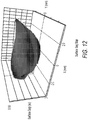
Fig. 12 is a surface SAG map of the polynomial surface ofFig. 1 , in accordance with an illustrative embodiment. -
Fig. 13 is diagram of a method to generate the polynomial surface ofFig. 1 , in accordance with an illustrative embodiment. -
Fig. 14 is a diagram of an example computing device configured to generate the polynomial surface disclosed herein. - Each and every feature described herein, and each and every combination of two or more of such features, is included within the scope of the present invention provided that the features included in such a combination are not mutually inconsistent.
- Embodiments of the present invention are generally directed to toric lenses or surface shapes, and/or related methods and systems for fabrication and use thereof. Toric lenses according to embodiments of the present disclosure find particular use in or on the eyes of human or animal subjects. Embodiments of the present disclosure are illustrated below with particular reference to intraocular lenses; however, other types of lenses fall within the scope of the present disclosure. Embodiments of the present disclosure provide improved ophthalmic lens (including, for example, contact lenses, and intraocular lenses, corneal lenses and the like) and include monofocal refractive lenses, monofocal diffractive lenses, bifocal refractive lenses, bifocal diffractive lenses, and multifocal refractive lenses, multifocal diffractive lenses.
- As used herein, the term "refractive optical power" or "refractive power" means optical power produced by the refraction of light as it interacts with a surface, lens, or optic. As used herein, the term "diffractive optical power" or "diffractive power" means optical power resulting from the diffraction of light as it interacts with a surface, lens, or optic.
- As used herein, the term "optical power" means the ability of a lens or optics, or portion thereof, to converge or diverge light to provide a focus (real or virtual), and is commonly specified in units of reciprocal meters (m-1) or Diopters (D). When used in reference to an intraocular lens, the term "optical power" means the optical power of the intraocular lens when disposed within a media having a refractive index of 1.336 (generally considered to be the refractive index of the aqueous and vitreous humors of the human eye), unless otherwise specified. Except where noted otherwise, the optical power of a lens or optic is from a reference plane associated with the lens or optic (e.g., a principal plane of an optic). As used herein, a cylinder power refers to the power required to correct for astigmatism resulting from imperfections of the cornea and/or surgically induced astigmatism.
- As used herein, the terms "about" or "approximately", when used in reference to a Diopter value of an optical power, mean within plus or minus 0.25 Diopter of the referenced optical power(s). As used herein, the terms "about" or "approximately", when used in reference to a percentage (%), mean within plus or minus one percent (±1%). As used herein, the terms "about" or "approximately", when used in reference to a linear dimension (e.g., length, width, thickness, distance, etc.) mean within plus or minus one percent (1%) of the value of the referenced linear dimension.
-
Fig. 1 is a diagram of cylindrical map of a polynomial surface 102 (also referred to as an ETA polynomial surface 102) that is uniformly arranged over a plurality of meridians that provides extended rotational tolerance, in accordance with an illustrative embodiment. Thepolynomial surface 102 is mapped to a surface of an ophthalmic apparatus 100 (not shown - seeFig. 6 ) to provide cylinder power to the ophthalmic apparatus, e.g., for the correction an astigmatism, or the like, such that the ophthalmic apparatus can be subjected to a cylindrical axis misalignment (CAM) (shown via arrow 104) of themeridian 106a of up to 10 degrees without degradation of the corrective performance (e.g., with regard to visual acuity (VA) or modular transfer function (MTF)), as compared to when there no misalignment. - Notably, the
polynomial surface 102 is uniformly arranged, in this embodiment, over a plurality ofmeridians 106 for every 0.5D (diopters). It should be appreciated that other values can be used. In some embodiments, thepolynomial surface 102 is uniformly arranged over a plurality ofmeridians 106 for every 0.41D (diopters). In some embodiments, thepolynomial surface 102 is uniformly arranged over a plurality ofmeridians 106 for every 0.42D (diopters). In some embodiments, thepolynomial surface 102 is uniformly arranged over a plurality ofmeridians 106 for every 0.44D (diopters). In some embodiments, thepolynomial surface 102 is uniformly arranged over a plurality ofmeridians 106 for every 0.46D (diopters). In some embodiments, thepolynomial surface 102 is uniformly arranged over a plurality ofmeridians 106 for every 0.45D (diopters). In some embodiments, thepolynomial surface 102 is uniformly arranged over a plurality ofmeridians 106 for every 0.48D (diopters). In some embodiments, thepolynomial surface 102 is uniformly arranged over a plurality ofmeridians 106 for every 0.52D (diopters). In some embodiments, thepolynomial surface 102 is uniformly arranged over a plurality ofmeridians 106 for every 0.54D (diopters). In some embodiments, thepolynomial surface 102 is uniformly arranged over a plurality ofmeridians 106 for every 0.56D (diopters). In some embodiments, thepolynomial surface 102 is uniformly arranged over a plurality ofmeridians 106 for every 0.58D (diopters). In some embodiments, thepolynomial surface 102 is uniformly arranged over a plurality ofmeridians 106 for every 0.60D (diopters). The number of the added power at which the meridian are uniformly distributed is set at an individual eye's tolerance of meridian power change such as the astigmatic or cylinder power. This value changes individually, up to 1.0D (diopters), but on average a comfortable tolerance is about 0.5D at the IOL plane. -
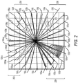
Fig. 2 is a diagram of theETA polynomial surface 102 ofFig. 1 shown with the plurality of uniformly arranged meridians 106 (shown as 106a-106ee), in accordance with an illustrative embodiment. As shown inFig. 2 (and inFig. 1 ), theETA polynomial surface 102, in this example, includes threeregions first region 202 spanning between meridians 106aa and 106dd; thesecond region 204 spanning betweenmeridians third region 206 spanning betweenmeridians - As shown in
Fig. 2 , meridian 106a is located at about 90 degrees; meridian 106b is located at about 79 degree; meridian 106c is located at about 67 degree; meridian 106d is located at about 55 degree; meridian 106e is located at about 44 degree; meridian 106f is located at about 33 degree; meridian 106g is located at about 24 degree; meridian 106h is located at about 11 degree; meridian 106i is located at about 0 degree; meridian 106j is located at about -12 degree; meridian 106k is located at about -24 degree; meridian 1061 is located at about -36 degree; meridian 106m is located at about -47 degree; meridian 106n is located at about -56 degree; meridian 106o is located at about -67 degree; meridian 106p is located at about -79 degree; and meridian 106q is located at about -90 degree; meridian 106r is located at about -100 degree; meridian 106s is located at about -112 degree; meridian 106t is located at about -125 degree; meridian 106u is located at about -135 degree; meridian 106v is located at about -145 degree; meridian 106w is located at about -158 degree; meridian 106x is located at about -176 degree; meridian 106y is located at about 168 degree; meridian 106z is located at about 157 degree; meridian 106aa is located at about 145 degree; meridian 106bb is located at about 133 degree; meridian 106cc is located at about 123 degree; meridian 106dd is located at about 113 degree; and meridian 106ee is located at about 101 degree. - It is contemplated that the
ETA polynomial surface 102 may include more than three regions of corrective cylindrical power, e.g., a fourth region, a fifth region, and etc. In such embodiments, the regions between the corrective meridians may be uniformly reduced, e.g., to about 10 degrees apart, about 9 apart, about 8 degrees apart, about 7 degrees apart, and etc. - Table 1 illustrates examples of toric IOL designs with meridians uniformly distributed for a same added power, for a 0.25D same added power, for a 0.5D same added power, for a same 0.75D same added power, and for a same 1.0D same added power.
Table 1 Added Power (in diopters) between each meridian Max Added Power (diopters) Number of meridians (from low to low power over ¼ of the lens) Max number of corrective regions 0.25 D 4 D 16 (4/0.25) 6 0.5 D 4 D 8 (4/0.5) 3 0.75 D 4 D 5.3 (4/0.75) 3 1.0 D 4 D 4(4/1) 3 - As shown in Table 1, when the meridians are uniformly arranged for a same added power of 0.5D, for a 4D base, there are 8 meridians between the high power meridian and the low power meridian in a quadrant of the polynomial surface between
meridian Fig. 2 . In another embodiment, when the meridians are uniformly arranged for a same added power of 0.75D, for a 4D base, there are 5.4 meridians between the high power meridian and the lower power. This allows up to 3 corrective regions of the polynomial surface. In another embodiment, when the meridians are uniformly arranged for a same added power of 0.25D, for a 4D base, there are 16 meridians between the high power meridian and the lower power. This allows up to 6 corrective regions of the polynomial surface. In another embodiment, when the meridians are uniformly arranged for a same added power of 1.0, for a 4D base, there are 2 meridians between the high power meridian and the lower power. This allows up to 3 corrective regions of the polynomial surface, which has the high power meridian center located atmeridians -
Fig. 3 is aprofile 300 of the polynomial surface ofFig. 1 with the plurality of uniformly arranged meridians, in accordance with an illustrative embodiment. As shown inFig. 3 , each meridian (e.g., 106b, 106c, 106d, 106e, 106f) is defined by an angular position that is uniformly arranged, about 11 degrees apart, for every 0.5D (diopters). In addition, the majority of meridian power change, from one meridian to the next, generates a change of more than 0.6D power difference (shown as 304). The result is aprofile 300 that is more uniformly sloped that provided extended range of operation beyond about 5 degrees of misalignment (e.g., up to 10 degrees misalignment), as compared to a conventional or macro regular cylindrical surface with power changes according to COS(2∗theta) trend, for a given difference between two meridians, shown asprofile 306. As shown inprofile 306, the meridian distribution is not uniform. Specifically, the meridian (in degrees) from the minimum power meridian - namely 0 degrees (308a) - is located at a 20.7-degree position (308b), a 30-degree position (308c), a 37.8-degree position (308d), a 45.0-degree position (308e), a 52.2-degree position (308f), a 60-degree position (308g), a 69.3-degree position (308h), a 90.0-degree positon (308i), and etc., in a periodic trend, which provides a non-uniform meridian difference of about 20.7 degrees (between 308a and 308b), about 9.3 degrees (between 308b and 308c), about 7.8 degrees (between 308c and 308d), about 7.2 degrees (between 308d and 308e), about 7.2 degrees (between 308e and 308f), about 7.8 degree (between 308f and 308g), about 9.3 (between 308g and 308h), and about 20.7 degree (between 308h and 308i). - Referring still to
Fig. 3 , off-center structures of thepolynomial surface 102 extend from the center structure in a gradually varying manner to apply cylinder power to a band of meridians surrounding the corrective meridian enabling the ophthalmic apparatus to operate off-axis (or off-meridian) to the corrective meridian (e.g., the astigmatism meridian). Notably, there are no more than 0.6-Diopter difference between any neighboring uniformly distributed contour lines. - In some embodiments, the
polynomial surface 102 is defined by a combination of spline or polynomial (e.g., a Zernike polynomial, a Chebyshev polynomial, or a combination of both) that is constrained by the condition of the meridians being uniformly arranged apart for every 0.5D (diopters). -
Fig. 4 illustrates an example operation of thepolynomial surface 102 ofFig. 1 when subjected to misalignment, in accordance with an illustrative embodiment. Thepolynomial surface 102, as a diffractive or refractive structure, in some embodiments, varies the extended depth of focus to a plurality of nearby focus points. To this end, light directed to such nearby focus points are thus directed to the desired focus point when the ophthalmic apparatus is subjected to a rotational offset from a primary intended axis of alignment, thereby extending the rotational tolerance of the apparatus to an extended tolerance band. InFig. 4 , a portion (402) of thepolynomial surface 102 has a focus point 404 (e.g., referred to as a "main focus point" 404, e.g., to correct for an astigmatism) that is generated by a region about thecenter 406 of theportion 402 of thepolynomial surface 102. In this example, anearby region 408 of thatportion 402 has a focus point 410 (e.g., referred to as an "auxiliary focus point" 410) that is offset from themain focus point 404. When thepolynomial surface 102 is rotated aboutaxis 412, e.g., asmisalignment 106 is introduced to the corrective meridian Θ = 0° (104), thefocus point 410 ofregion 408 is moved towards themain focus point 404, thereby extending the band of operation of thepolynomial surface 102. Remarkably, this extended tolerance astigmatism band delivers cylinder power to correct for the astigmatism for a range of meridians (e.g., up to ±10° as shown inFig. 1 , though can be more in other embodiments), thereby eliminating any need for additional corrective measures (e.g., supplemental corrective devices or another surgical intervention) when the implanted ophthalmic apparatus is not perfectly aligned to the desired astigmatism meridian in the eye. - Put another way, the
polynomial surface 102 facilitates an extended band of the corrective meridian that has minimal, and/or clinically acceptable, degradation of the visual acuity and modulation transfer function when the ophthalmic apparatus is subjected to rotational misalignment between the astigmatic axis and a center axis of the corrective meridian. -
Fig. 5 is a schematic drawing of a top view of ahuman eye 502, in which the natural lens of theeye 502 has been removed and replaced with an intraocular lens 100 (shown in simplified form inFig. 6 and in greater detail inFigs. 6A, 6B, 6C, and 6D ). Light enters from the left ofFIG. 5 , and passes through thecornea 504, theanterior chamber 506, theiris 508, and enters thecapsular bag 510. Prior to surgery, the natural lens occupies essentially the entire interior of thecapsular bag 510. After surgery, thecapsular bag 510 houses theintraocular lens 100, in addition to a fluid that occupies the remaining volume and equalizes the pressure in the eye. - After passing through the intraocular lens, light exits the posterior wall 512of the
capsular bag 510, passes through theposterior chamber 528, and strikes theretina 530, which detects the light and converts it to a signal transmitted through theoptic nerve 532 to the brain. Theintraocular lens 100 comprises an optic 524and may include one ormore haptics 526 that are attached to the optic 524 and may serve to center the optic 524 in the eye and/or couple the optic 5324 to thecapsular bag 510 and/orzonular fibers 520 of the eye. - The optic 524 has an
anterior surface 534 and a posterior surface 536, each having a particular shape that contributes to the refractive or diffractive properties of the lens. Either or both of these lens surfaces may optionally have an element made integral with or attached to the surfaces.Figs. 6A, 6B, 6C, and 6D are schematic diagrams of exemplary ophthalmic apparatuses that include the freeform-polynomial surface area 102, in accordance with an illustrative embodiment. Specifically,Figs. 6A and 6B show examples of diffractive lenses, andFigs. 6C and 6D show examples of refractive lenses. - Referring still to
Fig. 5 , theintraocular lens 100 includes polynomial surface 102 (as a refractive, diffractive, or both) that focus at a plurality of focus points that are offset radially to one another so as to provide an extended tolerance to misalignments of thelens 100 when implanted into theeye 502. That is, when the center axis of a corrective meridian is exactly matched to the desired astigmatic axis, only a first portion of the cylinder axis is focused at the desired point of focus (338) (e.g., at the retina) while second portions of the cylinder axis focuses at other points (540) nearby that are radially offset to the desired point of focus (538). To this end, when the primary axis of the astigmatism of the intraocular lens is rotationally offset (shown as arrow 542) with the astigmatism of the eye, the second portion of the cylinder axis focuses the light to the desired point of focus. - Artificial lenses (e.g., contact lenses or artificial intraocular lenses) can correct for certain visual impairments such as an inability of the natural lens to focus at near, intermediate or far distances; and/or astigmatism. Intraocular toric lenses have the potential for correcting astigmatism while also correcting for other vision impairments such as cataract, presbyopia, etc. However, in some patients, implanted intraocular toric lenses may not adequately correct astigmatism due to rotational misalignment of the corrective meridian of the lenses with the astigmatic meridian. In some patients following the surgical implant of the toric lenses, the corrective meridian of the implanted toric lenses can be rotationally misaligned to the astigmatic meridian, in some instances, by as much as 10 degrees. However, toric lenses that are designed to provide maximum correction (e.g., 1D to 9D) at the astigmatic meridian are subject to significant reduction in effectiveness of the correction due to any misalignment from the corrective meridian. In certain designs, it is observed that if the cylindrical power axis were mismatched by 1 degree, there would be about 3 percent reduction of the effectiveness of the correction. The degradation increases with the degree of misalignment. If there were a 10-degree misalignment, there would be about 35% reduction of the effectiveness of the correction. This effect is illustrated in
Fig. 7 discussed below. -
Figs. 7 and 8 include plots that illustrate the above-discussed degraded performance of conventional toric lens when subjected to rotational misalignments. This conventional toric lens is configured to provide 6.00 Diopters cylinder powers at the IOL plane, 4.11 Diopters cylinder power at the corneal plane, and a corneal astigmatism correction range (i.e., preoperative corneal astigmatism to predicted effects) between 4.00 and 4.75 Diopters. - Referring to
Fig. 7 , a plot of the undesired meridian power (also referred to as a residual meridian power ("OC")) (shown along the y-axis) added due to the rotational misalignments (shown along the x-axis) of the toric IOL is shown, including the residual powers for i) a negative 10-degree misalignment (shown as line 702), ii) a 0-degree misalignment (shown as line 704), and iii) a positive 10-degree misalignment (shown as line 706). As shown, the undesired added meridian power varies between a maximum of ± 0.75 Diopters at around the 45-degree meridian angle (shown as 708) and at about the 135-degree meridian angle (shown as 710). Notably, this undesired added meridian power is outside the tolerance of a healthy human eye, which can tolerant undesired effects up to about 0.4 Diopters (e.g., at the cornea plane) for normal visual acuity (i.e., "20/20 vision"). Because the undesired effects exceeds the astigmatism tolerance of the human eye, corrective prescription glasses, or further surgical operation to correct the implant misalignment, may be necessary to mitigate the effects of the misalignment of such toric IOLs. - This undesired meridian power, conventionally, may be expressed as
Equation 1 below.
- As shown in
Equation 1, θ is the correction meridian (also referred to as the cylindrical power axis) (in degrees); C is the astigmatic power (at the IOL plane) to be corrected at meridian θ (in Diopters); and α is the magnitude of rotational misalignment of the cylindrical power axis to the astigmatic axis (in degrees). -
Fig. 8 shows a plot illustrating the tolerance of a toric IOL to misalignment (shown in the y-axis) and a corresponding cylindrical power that may be applied (shown in the x-axis) for each misalignment to not exceed the astigmatism tolerance of the human eye (i.e., degrade the overall visual acuity). The tolerance to misalignment may be calculated as |α| ≤

-
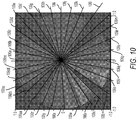
Fig. 9 shows a combined cylinder map generated from the combination of the IOL cylindrical power (provided, in part, via the polynomial surface) combined with the corneal cylindrical power through meridians.Fig. 10 shows the combined cylinder map ofFig. 9 with the meridians shown inFig. 2 superimposed thereon. - As discussed above with reference to
Fig. 1 , and as can be seen from the IOL cylinder map through meridians around the clock, there is remarkably no more than about 0.6D difference for any continuous uniformly distributed contour lines at the IOL plane. The IOL SE is 20D at the IOL plane. The IOL cylinder map ofFig. 1 is combined with the IOL SE to provide the overall IOL cylindrical map. That is, the astigmatism associated with test corneal cylindrical power has been attenuated and/or corrected for by the IOL cylindrical power provided, in part, by the polynomial surface. -
Figs. 11A and 11B each shows calculated MTF values as spatial frequencies of an exemplifiedIOL 100 in a physiological eye model with astigmatic cornea in different cylindrical axis misalignment (CAM) situations between the cornea and the IOL for an iris pupil. Notably, as shown inFigs. 11A and 11B , the modulation transfer function (MTF) is maintained across the extended range of alignment for a lens configured with the freeform-polynomial surface area 102 ofFig. 1 . Specifically, inFigs. 11A and 11B , the MTFs for misalignment at 0 degrees, 5 degrees, and 10 degrees are shown (shown as "CAM = 0 Deg" 1102, "CAM = 5 Deg" 1104, and "CAM = 10 Deg" 1106). InFig. 11A , the iris pupil is about 3.0mm. InFig. 11B , the iris pupil is about 5.0mm. - Notably, as can also be seen from the MTF curves, there are no cut-offs of the spatial frequency beyond 100 cpd (cycles per degree), which for an IOL with SE (Spherical Equivalent) of 20D (Diopters), this spatial frequency is approximately 30 cpd.
- In another aspect, the
polynomial surface 102 ofFig. 1 is optimized to purposely place accumulated high surface amplitude (also referred to high order aberration) to non-functional retinal area so that the functional areas can fully benefit the ETA designs, that is, the enhanced image quality stability. Examples of non-functional retinal areas may include, but not limited to, areas of gradual loss of sight (e.g., associated with glaucoma or retinal macular degeneration (AMD). - Referring to
Fig. 2 , an accumulated high surface amplitude results atarea 208 to provide enhanced image quality stability for the threecorrective regions surface amplitude area 208 is purposely positioned (in a manner similar to the positioning of thecorrective regions -
Fig. 12 is a surface SAG map of thepolynomial surface 102 ofFig. 1 , in accordance with an illustrative embodiment. -
Fig. 13 is diagram of amethod 1300 to generate, via a processor, the polynomial surface ofFig. 1 , in accordance with an illustrative embodiment. As shown inFig. 13 , themethod 1300 includes generating (1302), via a processor, an initial design (1304) comprising a base surface (with base cylindrical power) and sectional enhancements (with added cylindrical power in which each meridian is uniformly arranged for a same given added power) and iteratively generating (1308) and evaluating, a revised design (1310), generated according to an optimization routine (1308) that is performed based on sectional parameters, until pre-defined image quality metric values and boundary parameter are achieved. The sectional enhancements power of the initial design and the iterative design is the ETA polynomial surface ofFig. 1 . - Referring still to
Fig. 13 , themethod 1300 includes generating (1302) a first design (1304) via i) initial surface optical parameter, including a) base surfaceoptical parameters 1312 and b) sectional surface optical parameters 1314, and ii) the pre-defined image quality metric values 1316. The base surfaceoptical parameters 1312 include, in some embodiments, parameters associated with a radius of curvature for the toric lens (shown as "Radius of curvature" 1318), parameters associated with conic constant and aspheric coefficients (shown as "Conic constant" 1320), parameters associated with base cylinder power (shown as "Cylinder power" 1322), and parameters associated lens and/or coating material characteristics such as refractive index (shown as "Refractive index" 1324). Other parameters may be used as part of the base surfaceoptical parameters 1312. The section surface optical parameters 1314, in some embodiments, includes parameters associated with sectional added power and meridian characteristics (shown as "Sectional add power" 1328) and parameters associated with high order aberration characteristics, e.g., Zernike aberrations above second-order (shown as "High order aberrations" 1328). - Referring still to
Fig. 13 , the parameters associated with the sectional addedpower 1326, in some embodiments, include a cylindrical power, for a given optical zone, for a same given added power in which meridians are uniformly arranged. In some embodiments, the cylindrical power for the added power are all refractive. The parameters associated with the highorder aberration characteristics 1328, in some embodiments, include polynomial values (e.g., based on Zernike polynomials, Chebyshev polynomials, and combinations thereof) or characteristics such as polynomial orders and types as well as meridian boundaries for the high order aberrations. The high order aberration is constrained, e.g., from minimum to maximum cylindrical power over one or more meridian sections. In some embodiments, the high order aberrations is constrained or designated to a meridian, e.g., that corresponds to a corneal irregular geometry or limited retinal area functions. In such embodiments, the high order aberrations and its meridian locations on the lens surface may be optimized prior to the meridians for the uniform regions are determined to facilitate a customized design that is tailored for a given patient (i.e., particularly in view of corneal irregular geometry or limited retinal area functions). Such customization has a potential to truly benefit patients having cornea with or without astigmatism, patients with local Keratoconus with or without astigmatism, patients with glaucoma, patients with retinal macular degeneration (AMD), and the like. - Referring still to
Fig. 13 , the parameters associated with the pre-defined image qualitymetric value 1316 includes parameters associated with expected image quality metric (shown as "Expected image quality metric values" 1330) and parameters associated with special boundary restrain parameters (shown as "Special boundary restrain parameters" 1332). In some embodiments, image quality metric is based a comparison of a base polychromatic diffraction MTF (modular transfer function) (e.g., tangential and sagittal) to a number of error polychromatic diffraction MTFs values, e.g., where one or more polychromatic diffraction MTFs are determined for one or more misalignments of the generated toric lens from its intended operating meridians, e.g., at 5-degree misalignment and at 10-degree misalignment. - Referring still to
Fig. 13 , the initial design (1304) is evaluated (1334a) to determine image quality metric values (e.g., the base polychromatic diffraction MTF, e.g., at 0 degree misalignment) and the error polychromatic diffraction MTFs, e.g., at the 5 and 10 degrees misalignment) and boundary parameters, e.g., as shown inFigs. 11A and 11B . The determined image quality metric values are evaluated (1336) to determine whether the image quality metric values and boundary parameters meet an expected outcome, e.g., a value of 0.2. In some embodiments, the expected outcome is whether there is no cut off through spatial frequency beyond 100 cpd. Upon determining that the condition is met, themethod 1300 is stop (1338). It is contemplated that other image quality metrics may be used, e.g., the optical transfer function (OTF), phase transfer function (PhTF), and etc. - Where the condition is not met, the
method 1300 adjusts (1308) sectional parameters to be optimized and rerun the optimization to generate the reviseddesign 1310. The adjusted sectional parameters may include meridians locations and meridian spacing among neighboring meridians. The optimization may include allowing the uniform contour lines to move from one meridian to a next meridian up based on an upper limit amount and a lower limit amount. As shown inFig. 2 , theuniform contour line 210 is show transitioning frommeridian 106m tomeridian 106n. The transition is constrained to occur along a specific radial position and without abrupt transition points. - Referring back to
Fig. 13 , themethod 1300 then includes evaluating (1334b) the reviseddesign 1310 to determine image quality metric values (e.g., the base polychromatic diffraction MTF, e.g., at 0 degree misalignment) and the error polychromatic diffraction MTFs, e.g., at the 5 and 10 degrees misalignment) and boundary parameters, as discussed in relation to step 1334a, and re-evaluating (1336) whether the revised image quality metric values and boundary parameters meet the expected outcome, as discussed in relation to step 1336. - In some embodiments, the
method 1300 is performed in an optical and illumination design tool such as Zemax (Kirkland, WA). It is contemplated that themethod 1300 can be performed in other simulation and/or design environment. - The present technology may be used, for example, in the Tecnis toric intraocular lens product line as manufactured by Abbott Medical Optics, Inc. (Santa Ana, CA).
- It is not the intention to limit the disclosure to embodiments disclosed herein. Other embodiments may be used that are within the scope and spirit of the disclosure. In some embodiments, the above disclosed angularly varying phase members may be used for multifocal toric, extended range toric, and other categorized IOLs for extended tolerance of astigmatism caused by factors including the cylindrical axis misalignment. In addition, the above disclosed angularly varying phase members may be applied to spectacle, contact lens, corneal inlay, anterior chamber IOL, or any other visual device or system.
-
Fig. 14 is a diagram of an example computing device configured to generate the polynomial surface disclosed herein. As used herein, "computer" may include a plurality of computers. The computers may include one or more hardware components such as, for example, aprocessor 1421, a random access memory (RAM)module 1422, a read-only memory (ROM)module 1423, astorage 1424, adatabase 1425, one or more input/output (I/O)devices 1426, and aninterface 1427. Alternatively and/or additionally, controller 1420 may include one or more software components such as, for example, a computer-readable medium including computer executable instructions for performing a method associated with the exemplary embodiments. It is contemplated that one or more of the hardware components listed above may be implemented using software. For example,storage 1424 may include a software partition associated with one or more other hardware components. It is understood that the components listed above are exemplary only and not intended to be limiting. -
Processor 1421 may include one or more processors, each configured to execute instructions and process data to perform one or more functions associated with a computer for indexing images.Processor 1421 may be communicatively coupled toRAM 1422,ROM 1423,storage 1424,database 1425, I/O devices 1426, andinterface 1427.Processor 1421 may be configured to execute sequences of computer program instructions to perform various processes. The computer program instructions may be loaded intoRAM 1422 for execution byprocessor 1421. As used herein, processor refers to a physical hardware device that executes encoded instructions for performing functions on inputs and creating outputs. -
RAM 1422 andROM 1423 may each include one or more devices for storing information associated with operation ofprocessor 1421. For example,ROM 1423 may include a memory device configured to access and store information associated with controller 1420, including information associated with IOL lenses and their parameters.RAM 1422 may include a memory device for storing data associated with one or more operations ofprocessor 1421. For example,ROM 1423 may load instructions intoRAM 1422 for execution byprocessor 1421. -
Storage 1424 may include any type of mass storage device configured to store information thatprocessor 1421 may need to perform processes consistent with the disclosed embodiments. For example,storage 1424 may include one or more magnetic and/or optical disk devices, such as hard drives, CD-ROMs, DVD-ROMs, or any other type of mass media device. -
Database 1425 may include one or more software and/or hardware components that cooperate to store, organize, sort, filter, and/or arrange data used by controller 1420 and/orprocessor 1421. For example,database 1425 may store hardware and/or software configuration data associated with input-output hardware devices and controllers, as described herein. It is contemplated thatdatabase 1425 may store additional and/or different information than that listed above. - I/
O devices 1426 may include one or more components configured to communicate information with a user associated with controller 1420. For example, I/O devices may include a console with an integrated keyboard and mouse to allow a user to maintain a database of images, update associations, and access digital content. I/O devices 1426 may also include a display including a graphical user interface (GUI) for outputting information on a monitor. I/O devices 1426 may also include peripheral devices such as, for example, a printer for printing information associated with controller 1420, a user-accessible disk drive (e.g., a USB port, a floppy, CD-ROM, or DVD-ROM drive, etc.) to allow a user to input data stored on a portable media device, a microphone, a speaker system, or any other suitable type of interface device. -
Interface 1427 may include one or more components configured to transmit and receive data via a communication network, such as the Internet, a local area network, a workstation peer-to-peer network, a direct link network, a wireless network, or any other suitable communication platform. For example,interface 1427 may include one or more modulators, demodulators, multiplexers, demultiplexers, network communication devices, wireless devices, antennas, modems, and any other type of device configured to enable data communication via a communication network. - While the methods and systems have been described in connection with preferred embodiments and specific examples, it is not intended that the scope be limited to the particular embodiments set forth, as the embodiments herein are intended in all respects to be illustrative rather than restrictive.
- Unless otherwise expressly stated, it is in no way intended that any method set forth herein be construed as requiring that its steps be performed in a specific order. Accordingly, where a method claim does not actually recite an order to be followed by its steps or it is not otherwise specifically stated in the claims or descriptions that the steps are to be limited to a specific order, it is no way intended that an order be inferred, in any respect. This holds for any possible non-express basis for interpretation, including: matters of logic with respect to arrangement of steps or operational flow; plain meaning derived from grammatical organization or punctuation; the number or type of embodiments described in the specification.
- The disclosure additionally includes the following embodiments:
-
Embodiment 1. An ophthalmic apparatus having regions of one or more base spherical powers and one or more cylinder powers that are added to the one or more base spherical power for correcting an astigmatism (e.g., an intended astigmatism), the apparatus comprising one or more optical zones, including an optical zone defined by a polynomial-based surface coincident at a plurality of meridians having distinct cylinder powers,
wherein light incident to a given region of a given meridian of each of the plurality of meridians, and respective regions nearby, is directed to a given point of focus such that the regions nearby to the given region direct light to the given point of focus when the given meridian is rotationally offset from the given region, thereby establishing an extended band of operation, and
wherein each of the plurality of meridians is uniformly arranged on the optical zone for a same given added diopter of power up to 1.0D. -
Embodiment 2. The ophthalmic apparatus ofembodiment 1, wherein differences among each continuously uniformly distributed contour line, at a given IOL plane, associated with a given meridian of the plurality of meridians is less than about 0.6D (diopters). - Embodiment 3. The ophthalmic apparatus of
embodiment -
Embodiment 4. The ophthalmic apparatus of any one of embodiment s 1-3, wherein the polynomial-based surface establishes the extended band of operation across a range selected from the group consisting of about +5 degrees, about +6 degrees, about +7 degrees, about +8 degrees, about +9 degrees, about +10 degrees, about +11 degrees, about +12 degrees, about +13, degrees, about +14 degrees, and about +15 degrees.Embodiment 5. The ophthalmic apparatus of any one of embodiment s 1-4, wherein the polynomial-based surface is characterized by a series of weighted cosine-based functions. - Embodiment 6. The ophthalmic apparatus of any one of embodiment s 1-5, wherein the plurality of meridians include a first meridian, a second meridian, and a third meridian, each having the extended band of operation of at least 10 degrees.
- Embodiment 7. The ophthalmic apparatus of
embodiment 5, wherein a first center of the first meridian is angularly spaced about 90 degrees to a second center of the second meridian. - Embodiment 8. The ophthalmic apparatus of embodiment 6 or 7, wherein the optical zone comprises a fourth meridian having an accumulated high surface amplitude such that the first meridian, the second meridian, and the third meridian have the established extended band of operation.
- Embodiment 9. The ophthalmic apparatus of embodiment 8, wherein the fourth meridian is purposely positioned at an angular position that coincides with a diagnosed limited retinal functional area of a patient.
-
Embodiment 10. The ophthalmic apparatus of any one of embodiment s 1-9, wherein the polynomial-based surface comprises a refractive surface. -
Embodiment 11. The ophthalmic apparatus of any one of embodiment s 1-10, wherein the polynomial-based surface comprises a diffractive surface. - Embodiment 12. The ophthalmic apparatus of any one of embodiment s 1-11, wherein an offset of each meridian of the plurality of meridians of about 10 degrees causes a MTF (modulation transfer function) measure change of less than 10% at 30 cycles per degree (cpd).
- Embodiment 13. The ophthalmic apparatus of any one of embodiment s 1-12, wherein the polynomial-bases surface at a first meridian and at a second meridian comprises a bifocal monofocal lens.
- Embodiment 14. The ophthalmic apparatus of any one of embodiment s 1-13, wherein the polynomial-bases surface at a first meridian comprises a monofocal lens.
- Embodiment 15. The ophthalmic apparatus of any one of embodiment s 1-14, wherein the polynomial-bases surface at a first meridian comprises an extended range lens.
- Embodiment 16. The ophthalmic apparatus of any one of embodiment s 1-15, comprising:
an accumulated high surface amplitude area disposed at coordinates that coincides with non-functional or limited functional retinal regions of a given patient. - Embodiment 17. A rotationally-tolerant ophthalmic apparatus for correcting astigmatism, the ophthalmic apparatus comprising a multi-zonal lens body having a plurality of optical zones configured to apply cylinder power at an astigmatism meridian of an eye,
the multi-zonal lens body forming a angularly-varying phase member having a peak cylinder power centered at an astigmatism correcting meridian, the angularly-varying phase member at the peak cylinder power being configured to direct light to a first point of focus on the retina, and
wherein the angularly- varying phase member varies, at each optical zone, along meridians nearby to the astigmatism correcting meridian to direct light to points of focus nearby to the first point of focus such the multi-zonal lens body, when rotational offset from the peak cylinder power, directs light from the nearby points of focus to the first point of focus, thereby establishing a band of operational meridians over the astigmatism meridian, and
wherein the angularly-varying phase member has a profile that is uniformly spaced for every 0.5D (diopters). - Embodiment 18. The apparatus of embodiment 17, wherein the band of operation is established across a range selected from the group consisting of about +5 degrees, about +6 degrees, about +7 degrees, about +8 degrees, about +9 degrees, about +10 degrees, about +11 degrees, about +12 degrees, about +13, degrees, about +14 degrees, and about +15 degrees.
- Embodiment 19. The apparatus of embodiment 17 or 18, wherein the polynomial-based surface is characterized by a series of weighted cosine-based function.
- Embodiment 20. The apparatus of any one of embodiment s 17-19, wherein the angularly-varying phase member has a band of operation of at least 10 degrees.
- Embodiment 21. The apparatus of any one of embodiment s 17-20, wherein the multi-zonal lens body forms a second angularly-varying phase member having a second peak cylinder power centered at a second correcting meridian, the second angularly-varying phase member at the second peak cylinder power being configured to direct light to a second point of focus on the retina, and
wherein the second angularly-varying phase member varies, at each optical zone, along meridians nearby to the second correcting meridian to direct light to points of focus nearby to the second point of focus such the multi-zonal lens body, when rotational offset from the second peak cylinder power, directs light from the nearby points of focus to the second point of focus, and
wherein the second angularly-varying phase member has the profile that is uniformly spaced for every 0.5D (diopters). - Embodiment 22. The apparatus of any one of embodiment s 17-21, wherein the multi-zonal lens body forms a second angularly-varying phase member having a second peak cylinder power centered at a second correcting meridian, the second angularly-varying phase member at the second peak cylinder power being configured to direct light to a second point of focus on the retina, and
wherein the second angularly-varying phase member varies, at each optical zone, along meridians nearby to the second correcting meridian to direct light to points of focus nearby to the second point of focus such the multi-zonal lens body, when rotational offset from the second peak cylinder power, directs light from the nearby points of focus to the second point of focus, and
wherein the second angularly-varying phase member has a second profile that is uniformly spaced for a same given added diopter of power up to 1.0D.
Claims (15)
- An ophthalmic apparatus having regions of one or more base spherical powers and one or more cylinder powers that are added to the one or more base spherical power for correcting an astigmatism (e.g., an intended astigmatism), the apparatus comprising one or more optical zones, including an optical zone defined by a polynomial-based surface coincident at a plurality of meridians having distinct cylinder powers,
wherein light incident to a given region of a given meridian of each of the plurality of meridians, and respective regions nearby, is directed to a given point of focus such that the regions nearby to the given region direct light to the given point of focus when the given meridian is rotationally offset from the given region, thereby establishing an extended band of operation, and
wherein each of the plurality of meridians is uniformly arranged on the optical zone for a same given added diopter of power up to 1.0D. - The ophthalmic apparatus of claim 1, wherein differences among each continuously uniformly distributed contour line, at a given IOL plane, associated with a given meridian of the plurality of meridians is less than about 0.6D (diopters).
- The ophthalmic apparatus of claim 1 or 2, wherein the same given added diopter is about 0.5D (diopters).
- The ophthalmic apparatus of any one of claims 1-3, wherein the polynomial-based surface establishes the extended band of operation across a range selected from the group consisting of about +5 degrees, about +6 degrees, about +7 degrees, about +8 degrees, about +9 degrees, about +10 degrees, about +11 degrees, about +12 degrees, about +13, degrees, about +14 degrees, and about +15 degrees.
- The ophthalmic apparatus of any one of claims 1-4, wherein the polynomial-based surface is characterized by a series of weighted cosine-based functions.
- The ophthalmic apparatus of any one of claims 1-5, wherein the plurality of meridians include a first meridian, a second meridian, and a third meridian, each having the extended band of operation of at least 10 degrees.
- The ophthalmic apparatus of claim 5, wherein a first center of the first meridian is angularly spaced about 90 degrees to a second center of the second meridian.
- The ophthalmic apparatus of claim 6 or 7, wherein the optical zone comprises a fourth meridian having an accumulated high surface amplitude such that the first meridian, the second meridian, and the third meridian have the established extended band of operation, optionally wherein the fourth meridian is purposely positioned at an angular position that coincides with a diagnosed limited retinal functional area of a patient.
- The ophthalmic apparatus of any one of claims 1-8, wherein the polynomial-based surface comprises a refractive surface.
- The ophthalmic apparatus of any one of claims 1-9, wherein the polynomial-based surface comprises a diffractive surface.
- The ophthalmic apparatus of any one of claims 1-10, wherein an offset of each meridian of the plurality of meridians of about 10 degrees causes a MTF (modulation transfer function) measure change of less than 10% at 30 cycles per degree (cpd).
- The ophthalmic apparatus of any one of claims 1-11, wherein the polynomial-bases surface at a first meridian and at a second meridian comprises a bifocal monofocal lens.
- The ophthalmic apparatus of any one of claims 1-12, wherein the polynomial-bases surface at a first meridian comprises a monofocal lens.
- The ophthalmic apparatus of any one of claims 1-13, wherein the polynomial-bases surface at a first meridian comprises an extended range lens.
- The ophthalmic apparatus of any one of claims 1-14, comprising:an accumulated high surface amplitude area disposed at coordinates that coincides with non-functional or limited functional retinal regions of a given patient.
Applications Claiming Priority (4)
| Application Number | Priority Date | Filing Date | Title |
|---|---|---|---|
| US201662312321P | 2016-03-23 | 2016-03-23 | |
| US201662312338P | 2016-03-23 | 2016-03-23 | |
| PCT/US2017/023888 WO2017165695A1 (en) | 2016-03-23 | 2017-03-23 | Ophthalmic apparatus with corrective meridians having extended tolerance band by modifying refractive powers in uniform meridian distribution |
| EP17715875.5A EP3432829B1 (en) | 2016-03-23 | 2017-03-23 | Ophthalmic apparatus with corrective meridians having extended tolerance band by modifying refractive powers in uniform meridian distribution |
Related Parent Applications (2)
| Application Number | Title | Priority Date | Filing Date |
|---|---|---|---|
| EP17715875.5A Division EP3432829B1 (en) | 2016-03-23 | 2017-03-23 | Ophthalmic apparatus with corrective meridians having extended tolerance band by modifying refractive powers in uniform meridian distribution |
| EP17715875.5A Division-Into EP3432829B1 (en) | 2016-03-23 | 2017-03-23 | Ophthalmic apparatus with corrective meridians having extended tolerance band by modifying refractive powers in uniform meridian distribution |
Publications (2)
| Publication Number | Publication Date |
|---|---|
| EP3656350A1 true EP3656350A1 (en) | 2020-05-27 |
| EP3656350B1 EP3656350B1 (en) | 2021-06-23 |
Family
ID=58489422
Family Applications (4)
| Application Number | Title | Priority Date | Filing Date |
|---|---|---|---|
| EP17715875.5A Active EP3432829B1 (en) | 2016-03-23 | 2017-03-23 | Ophthalmic apparatus with corrective meridians having extended tolerance band by modifying refractive powers in uniform meridian distribution |
| EP17715873.0A Active EP3433667B1 (en) | 2016-03-23 | 2017-03-23 | Ophthalmic apparatus with corrective meridians having extended tolerance band with freeform refractive surfaces |
| EP19219661.6A Active EP3656350B1 (en) | 2016-03-23 | 2017-03-23 | Ophthalmic apparatus with corrective meridians having extended tolerance band by modifying refractive powers in uniform meridian distribution |
| EP17715869.8A Active EP3432828B1 (en) | 2016-03-23 | 2017-03-23 | Ophthalmic apparatus with corrective meridians having extended tolerance band |
Family Applications Before (2)
| Application Number | Title | Priority Date | Filing Date |
|---|---|---|---|
| EP17715875.5A Active EP3432829B1 (en) | 2016-03-23 | 2017-03-23 | Ophthalmic apparatus with corrective meridians having extended tolerance band by modifying refractive powers in uniform meridian distribution |
| EP17715873.0A Active EP3433667B1 (en) | 2016-03-23 | 2017-03-23 | Ophthalmic apparatus with corrective meridians having extended tolerance band with freeform refractive surfaces |
Family Applications After (1)
| Application Number | Title | Priority Date | Filing Date |
|---|---|---|---|
| EP17715869.8A Active EP3432828B1 (en) | 2016-03-23 | 2017-03-23 | Ophthalmic apparatus with corrective meridians having extended tolerance band |
Country Status (5)
| Country | Link |
|---|---|
| US (6) | US10670885B2 (en) |
| EP (4) | EP3432829B1 (en) |
| AU (3) | AU2017237090B2 (en) |
| CA (1) | CA3018558C (en) |
| WO (3) | WO2017165679A1 (en) |
Families Citing this family (14)
| Publication number | Priority date | Publication date | Assignee | Title |
|---|---|---|---|---|
| US10004596B2 (en) | 2014-07-31 | 2018-06-26 | Lensgen, Inc. | Accommodating intraocular lens device |
| CN109725441A (en) * | 2017-10-28 | 2019-05-07 | 郑克立 | A kind of holographic glasses piece |
| CN108836571B (en) * | 2018-07-13 | 2024-05-28 | 爱博诺德(北京)医疗科技股份有限公司 | Artificial lens |
| US20220334409A1 (en) * | 2019-09-25 | 2022-10-20 | Nthalmic Holding Pty Ltd | A contact lens solution for myopia management |
| CN110711050B (en) * | 2019-10-24 | 2024-08-23 | 西安眼得乐医疗科技有限公司 | Intraocular lens |
| US11963868B2 (en) | 2020-06-01 | 2024-04-23 | Ast Products, Inc. | Double-sided aspheric diffractive multifocal lens, manufacture, and uses thereof |
| JP2023539150A (en) * | 2020-08-21 | 2023-09-13 | ブリエン ホールデン ビジョン インスティチュート リミテッド | Ophthalmic devices, systems and/or methods for managing ocular diseases and/or reducing night vision impairment |
| WO2022011359A1 (en) * | 2020-08-27 | 2022-01-13 | E-Vision Smart Optics, Inc. | Electroactive lenses with cylinder rotational control |
| US12105361B2 (en) * | 2020-12-18 | 2024-10-01 | Coopervision International Limited | Myopia-control contact lenses and methods relating thereto |
| US12239529B2 (en) | 2021-03-09 | 2025-03-04 | Amo Groningen B.V. | Refractive extended depth of focus intraocular lens, and methods of use and manufacture |
| US20230036893A1 (en) * | 2021-07-30 | 2023-02-02 | Coopervision International Limited | Ophthalmic lenses having a photopolymer layer with grin elements |
| AU2023208433B2 (en) | 2022-01-19 | 2026-05-07 | Coopervision International Limited | Contact lenses and methods relating thereto |
| CA3257414A1 (en) * | 2022-06-21 | 2023-12-28 | Coopervision International Limited | Contact lenses and methods relating thereto |
| DE102023106207A1 (en) | 2023-03-13 | 2024-09-19 | Carl Zeiss Meditec Ag | Ophthalmic lens with extended depth of field and method for producing a lens design |
Citations (3)
| Publication number | Priority date | Publication date | Assignee | Title |
|---|---|---|---|---|
| US20110166652A1 (en) * | 2007-08-27 | 2011-07-07 | Amo Groningen B.V. | Toric lens with decreased sensitivity to cylinder power and rotation and method of using the same |
| US20110205486A1 (en) * | 2010-02-25 | 2011-08-25 | Abbott Medical Optics, Inc. | Toric optic for ophthalmic use |
| WO2012085917A1 (en) * | 2010-12-23 | 2012-06-28 | Xceed Imaging Ltd. | Toric ophthalmic lens having extended depth of focus |
Family Cites Families (296)
| Publication number | Priority date | Publication date | Assignee | Title |
|---|---|---|---|---|
| US2077092A (en) | 1936-01-13 | 1937-04-13 | Broder Simon | Ophthalmic lens |
| GB1054972A (en) | 1963-02-22 | |||
| US3305294A (en) | 1964-12-03 | 1967-02-21 | Optical Res & Dev Corp | Two-element variable-power spherical lens |
| US3735685A (en) | 1971-05-07 | 1973-05-29 | Polaroid Corp | Reflective imaging apparatus |
| US4056311A (en) * | 1973-08-16 | 1977-11-01 | American Optical Corporation | Progressive power ophthalmic lens having a plurality of viewing zones with non-discontinuous variations therebetween |
| US4010496A (en) | 1975-10-01 | 1977-03-08 | Neefe Charles W | Bifocal lens which positions within the anterior chamber |
| US4162122A (en) | 1977-09-14 | 1979-07-24 | Cohen Allen L | Zonal bifocal contact lens |
| US4210391A (en) | 1977-09-14 | 1980-07-01 | Cohen Allen L | Multifocal zone plate |
| US4340283A (en) | 1978-12-18 | 1982-07-20 | Cohen Allen L | Phase shift multifocal zone plate |
| US4338005A (en) | 1978-12-18 | 1982-07-06 | Cohen Allen L | Multifocal phase place |
| US4319564A (en) | 1980-01-03 | 1982-03-16 | Karickhoff John R | Instrument for measurement of the diameter of the anterior chamber of the eye |
| USRE32525F1 (en) | 1980-04-01 | 1989-05-09 | Universal intraocular lens and a method of measuring an eye chamber size | |
| US4377873A (en) | 1980-10-30 | 1983-03-29 | Reichert Jr Henry L | Intraocular lens |
| US4480340A (en) | 1981-02-18 | 1984-11-06 | Shepard Dennis D | Intraocular lens with resilient support means |
| DE3107675C2 (en) | 1981-02-28 | 1985-06-20 | Elektro-Physik Hans Nix & Dr.-Ing. E. Steingroever KG, 5000 Köln | Method and device for the electronic measurement of the thickness of very thin electrically conductive layers on a non-conductive substrate |
| DE8107675U1 (en) | 1981-03-03 | 1981-07-30 | Porsche Design Produkte Vertriebsgesellschaft mbH, 5020 Salzburg | "TRIANGLE RULER" |
| US4370760A (en) | 1981-03-25 | 1983-02-01 | Kelman Charles D | Anterior chamber intraocular lens |
| DE3265356D1 (en) | 1981-04-29 | 1985-09-19 | Pilkington Perkin Elmer Ltd | Artificial eye lenses |
| DE3119002A1 (en) | 1981-05-13 | 1982-12-02 | INPROHOLD Establishment, 9490 Vaduz | REAR CHAMBER IMPLANTATION LENS |
| US4403353A (en) | 1981-06-25 | 1983-09-13 | Tennant Jerald L | Anterior chamber implant lens |
| US4402579A (en) | 1981-07-29 | 1983-09-06 | Lynell Medical Technology Inc. | Contact-lens construction |
| US4446581A (en) | 1981-09-02 | 1984-05-08 | Blake L W | Intraocular lens with free-ended sizing prong |
| US4409691A (en) | 1981-11-02 | 1983-10-18 | Levy Chauncey F | Focussable intraocular lens |
| US4404694A (en) | 1982-03-18 | 1983-09-20 | Kelman Charles D | Intraocular lens |
| US4504982A (en) | 1982-08-05 | 1985-03-19 | Optical Radiation Corporation | Aspheric intraocular lens |
| DE3377535D1 (en) | 1982-10-27 | 1988-09-01 | Pilkington Plc | Bifocal contact lens comprising a plurality of concentric zones |
| US4593981A (en) | 1983-05-06 | 1986-06-10 | Master Contact Lens Labs Inc. | Bifocal contact lens |
| US4500382A (en) | 1983-06-10 | 1985-02-19 | Transilwrap Company, Inc. | Method of manufacture of resin film precision biomedical article |
| DE3431224A1 (en) | 1983-08-04 | 1986-03-06 | Steven B Siepser | Artificial intraocular lens |
| US4556998A (en) | 1983-08-04 | 1985-12-10 | Siepser Steven B | Artificial intraocular lenses and method for their surgical implantation |
| US4551864A (en) | 1983-08-18 | 1985-11-12 | Iolab Corporation | Anterior chamber lens |
| US4636049A (en) | 1983-09-20 | 1987-01-13 | University Optical Products Co. | Concentric bifocal contact lens |
| US4560383A (en) | 1983-10-27 | 1985-12-24 | Leiske Larry G | Anterior chamber intraocular lens |
| US4687484A (en) | 1983-12-12 | 1987-08-18 | Kaplan Linda J | Anterior chamber intraocular lens |
| GB8404817D0 (en) | 1984-02-23 | 1984-03-28 | Pilkington Perkin Elmer Ltd | Ophthalmic lenses |
| US4605409A (en) | 1984-05-21 | 1986-08-12 | Kelman Charles D | Intraocular lens with miniature optic having expandable and contractible glare-reducing means |
| US4629460A (en) | 1984-06-25 | 1986-12-16 | Dyer Robert L | Intraocular lens |
| US4787904A (en) | 1984-07-06 | 1988-11-29 | Severin Sanford L | Hydrophillic intraocular lens |
| US4629462A (en) | 1984-07-13 | 1986-12-16 | Feaster Fred T | Intraocular lens with coiled haptics |
| SU1311063A1 (en) | 1984-09-27 | 1988-01-30 | Московский научно-исследовательский институт микрохирургии глаза | Eye artificial lens |
| DE3439551A1 (en) | 1984-10-29 | 1986-04-30 | Inprohold Establishment, Vaduz | ONE-PIECE IMPLANTING LENS |
| FI79619C (en) | 1984-12-31 | 1990-01-10 | Antti Vannas | Intraocular lens |
| US4787903A (en) | 1985-07-24 | 1988-11-29 | Grendahl Dennis T | Intraocular lens |
| US4781717A (en) | 1985-07-24 | 1988-11-01 | Grendahl Dennis T | Intraocular lens |
| US4676791A (en) | 1985-08-01 | 1987-06-30 | Surgidev Corporation | Intraocular lens and method for making same |
| US4687485A (en) | 1985-08-23 | 1987-08-18 | Barnes-Hind, Inc. | Intraocular lens with leg means having compressible regions and/or color |
| US4681102A (en) | 1985-09-11 | 1987-07-21 | Bartell Michael T | Apparatus and method for insertion of an intra-ocular lens |
| US4834751A (en) | 1985-12-04 | 1989-05-30 | Allergan, Inc. | Staking ring for soft IOL |
| CA1283252C (en) | 1985-12-09 | 1991-04-23 | Albert C. Ting | Haptic to optic attachment for a soft iol |
| US5121979A (en) | 1986-05-14 | 1992-06-16 | Cohen Allen L | Diffractive multifocal optical device |
| US5144483A (en) | 1986-05-14 | 1992-09-01 | Cohen Allen L | Diffractive multifocal optical device |
| US4725277A (en) | 1986-05-14 | 1988-02-16 | Precision-Cosmet Co., Inc. | Intraocular lens with tapered haptics |
| US4676792A (en) | 1986-08-26 | 1987-06-30 | Donald Praeger | Method and artificial intraocular lens device for the phakic treatment of myopia |
| US4898461A (en) | 1987-06-01 | 1990-02-06 | Valdemar Portney | Multifocal ophthalmic lens |
| US5225858A (en) | 1987-06-01 | 1993-07-06 | Valdemar Portney | Multifocal ophthalmic lens |
| US5270744A (en) | 1987-06-01 | 1993-12-14 | Valdemar Portney | Multifocal ophthalmic lens |
| US4828558A (en) | 1987-07-28 | 1989-05-09 | Kelman Charles D | Laminate optic with interior Fresnel lens |
| US4778462A (en) | 1987-08-24 | 1988-10-18 | Grendahl Dennis T | Multiple element zone of focus artificial lens |
| US4795462A (en) | 1987-08-24 | 1989-01-03 | Grendahl Dennis T | Cylindrically segmented zone of focus artificial lens |
| US4798609A (en) | 1987-08-24 | 1989-01-17 | Grendahl Dennis T | Radially segmented zone of focus artificial lens |
| US4798608A (en) | 1987-08-24 | 1989-01-17 | Grendahl Dennis T | Laminated zone of focus artificial lens |
| US4834748A (en) | 1987-09-29 | 1989-05-30 | Allergan, Inc. | Method and apparatus for removing corneal tissue |
| US5047052A (en) | 1987-11-06 | 1991-09-10 | Seymour Dubroff | Anterior chamber intraocular lens with four point fixation |
| US4863539A (en) | 1987-11-06 | 1989-09-05 | Optical Radiation Corporation | Haptic attachment for intraocular lenses |
| US5054905A (en) | 1987-11-12 | 1991-10-08 | Cohen Allen L | Progressive intensity phase bifocal |
| US5056908A (en) | 1987-11-12 | 1991-10-15 | Cohen Allen L | Optic zone phase channels |
| US4881804A (en) | 1987-11-12 | 1989-11-21 | Cohen Allen L | Multifocal phase plate with a pure refractive portion |
| FR2631228B1 (en) | 1988-05-11 | 1990-08-10 | Domilens Laboratoires | INTRA-EYE IMPLANT OF PREVIOUS CHAMBER |
| US4932970A (en) | 1988-05-17 | 1990-06-12 | Allergan, Inc. | Ophthalmic lens |
| FR2631713B1 (en) | 1988-05-19 | 1990-08-31 | Essilor Int | DIFFRACTIVE LENS WITH MIXED PROFILE |
| ATE133796T1 (en) | 1988-07-20 | 1996-02-15 | Allen L Dr Cohen | MULTIFOCAL DIFFRACTIVE OPTICAL DEVICE |
| US4995714A (en) | 1988-08-26 | 1991-02-26 | Cohen Allen L | Multifocal optical device with novel phase zone plate and method for making |
| FR2642855B1 (en) | 1989-02-06 | 1991-05-17 | Essilor Int | OPTICAL LENS FOR THE CORRECTION OF ASTIGMATISM |
| US5121980A (en) | 1989-04-19 | 1992-06-16 | Cohen Allen L | Small aperture multifocal |
| US4997442A (en) | 1989-05-04 | 1991-03-05 | Alcon Laboratories, Inc. | Bicomposite intraocular lenses |
| US5078742A (en) | 1989-08-28 | 1992-01-07 | Elie Dahan | Posterior chamber lens implant |
| US5019097A (en) | 1989-11-22 | 1991-05-28 | Allergan, Inc. | Corneal onlay lenses and methods for attaching same |
| AU6978991A (en) | 1989-12-07 | 1991-07-18 | Leonard Seidner | Corneal contact lenses |
| US5089023A (en) | 1990-03-22 | 1992-02-18 | Massachusetts Institute Of Technology | Diffractive/refractive lens implant |
| US5096285A (en) | 1990-05-14 | 1992-03-17 | Iolab Corporation | Multifocal multizone diffractive ophthalmic lenses |
| US5225997A (en) | 1990-06-05 | 1993-07-06 | Sygnus Controls Inc. | Automatic monitoring and remote reporting device |
| US5147397A (en) | 1990-07-03 | 1992-09-15 | Allergan, Inc. | Intraocular lens and method for making same |
| US5117306A (en) | 1990-07-17 | 1992-05-26 | Cohen Allen L | Diffraction bifocal with adjusted chromaticity |
| US5120120A (en) | 1990-07-27 | 1992-06-09 | Cohen Allen L | Multifocal optical device with spurious order suppression and method for manufacture of same |
| US5229797A (en) | 1990-08-08 | 1993-07-20 | Minnesota Mining And Manufacturing Company | Multifocal diffractive ophthalmic lenses |
| US5173723A (en) | 1990-10-02 | 1992-12-22 | Volk Donald A | Aspheric ophthalmic accommodating lens design for intraocular lens and contact lens |
| US5066301A (en) | 1990-10-09 | 1991-11-19 | Wiley Robert G | Variable focus lens |
| US5258025A (en) | 1990-11-21 | 1993-11-02 | Fedorov Svjatoslav N | Corrective intraocular lens |
| US5217491A (en) | 1990-12-27 | 1993-06-08 | American Cyanamid Company | Composite intraocular lens |
| US5133749A (en) | 1991-05-13 | 1992-07-28 | Nordan Lee T | Centrating haptics |
| US5106180A (en) | 1991-05-30 | 1992-04-21 | Robert Marie | Multifocal ophthalmic lens |
| US5147395A (en) | 1991-07-16 | 1992-09-15 | Allergan Inc. | Small incision endocapsulator IOL |
| US5570143A (en) | 1991-08-09 | 1996-10-29 | Capricornia Contact Lens Pty. Ltd. | Toric lens with axis mislocation latitude |
| US5479220A (en) | 1991-10-09 | 1995-12-26 | Seiko Epson Corporation | Eyeglass lens |
| US5203790A (en) | 1991-11-12 | 1993-04-20 | Henry H. McDonald | Foldable plastic optical lens with reduced thickness light blocking segments, and anchoring means |
| US5184405A (en) | 1991-12-18 | 1993-02-09 | Jonathan Cress | Method and device for fitting toric contact lenses |
| US5476513A (en) | 1992-02-28 | 1995-12-19 | Allergan, Inc. | Intraocular lens |
| US5201763A (en) | 1992-02-28 | 1993-04-13 | Allergan, Inc. | Thin intraocular lens |
| US5197981A (en) | 1992-04-23 | 1993-03-30 | Alcon Surgical, Inc. | Intraocular lens having haptic of specific curvature and proportion |
| JP3160776B2 (en) | 1992-07-23 | 2001-04-25 | コニカ株式会社 | Silver halide photographic materials |
| US5760871A (en) | 1993-01-06 | 1998-06-02 | Holo-Or Ltd. | Diffractive multi-focal lens |
| US5748282A (en) | 1993-01-27 | 1998-05-05 | Pilkington Barnes Hind, Inc. | Multifocal contact lens |
| US5408281A (en) | 1993-04-26 | 1995-04-18 | Ciba-Geigy | Multifocal contact lens |
| US5571177A (en) | 1993-06-14 | 1996-11-05 | Allergan | IOL structured for post-operative re-positioning and method for post-operative IOL re-positioning |
| US5502518A (en) | 1993-09-09 | 1996-03-26 | Scient Optics Inc | Asymmetric aspheric contact lens |
| US5433745A (en) | 1993-10-13 | 1995-07-18 | Allergan, Inc. | Corneal implants and methods for producing same |
| JP3745394B2 (en) | 1994-07-04 | 2006-02-15 | 武敏 鈴木 | Intraocular lens |
| US5699142A (en) | 1994-09-01 | 1997-12-16 | Alcon Laboratories, Inc. | Diffractive multifocal ophthalmic lens |
| US5620720A (en) | 1994-11-29 | 1997-04-15 | Allergan | Cast molding of intraocular lenses |
| JPH08196507A (en) | 1995-01-23 | 1996-08-06 | Nikon Corp | Ophthalmic equipment |
| ATE272990T1 (en) | 1995-02-15 | 2004-08-15 | Medevec Licensing Bv | ADJUSTABLE INTRAOCULAR LENS WITH T-SHAPED BRACKETS |
| US7048997B2 (en) | 1995-03-03 | 2006-05-23 | Vision-Ease Lens | Production of optical elements |
| US5652638A (en) | 1995-05-04 | 1997-07-29 | Johnson & Johnson Vision Products, Inc. | Concentric annular ring lens designs for astigmatism |
| IL118065A0 (en) | 1995-05-04 | 1996-08-04 | Johnson & Johnson Vision Prod | Aspheric toric lens designs |
| US5801807A (en) | 1995-08-08 | 1998-09-01 | Nikon Corporation | Ophthalmic illumination device having adjustable transmittance member and microscope for operation using the same |
| US5968094A (en) | 1995-09-18 | 1999-10-19 | Emmetropia, Inc. | Compound intraocular lens |
| WO1997012564A1 (en) | 1995-10-06 | 1997-04-10 | Cumming J Stuart | Intraocular lenses with fixated haptics |
| US5716403A (en) | 1995-12-06 | 1998-02-10 | Alcon Laboratories, Inc. | Single piece foldable intraocular lens |
| FR2745711B1 (en) | 1996-03-05 | 1998-05-07 | Ioltechnologie Production | FLEXIBLE IMPLANT FORMING INTRAOCULAR LENS FOR POSTERIOR CHAMBER |
| CA2249584C (en) | 1996-03-21 | 2007-03-27 | Sola International Holdings Ltd. | Improved single vision lenses |
| FR2748200B1 (en) | 1996-05-03 | 1998-09-25 | W K Et Associes | FLEXIBLE MONOBLOCK INTRAOCULAR IMPLANT |
| US5864378A (en) | 1996-05-21 | 1999-01-26 | Allergan | Enhanced monofocal IOL or contact lens |
| US6015435A (en) | 1996-10-24 | 2000-01-18 | International Vision, Inc. | Self-centering phakic intraocular lens |
| CA2271783C (en) | 1996-11-20 | 2013-04-16 | Yale University | Survivin, a protein that inhibits cellular apoptosis, and its modulation |
| DE19724108C1 (en) | 1997-06-09 | 1998-11-19 | Morcher Gmbh | Capsule equatorial ring |
| US5928282A (en) | 1997-06-13 | 1999-07-27 | Bausch & Lomb Surgical, Inc. | Intraocular lens |
| JPH1114804A (en) | 1997-06-27 | 1999-01-22 | Fuji Photo Optical Co Ltd | Plastic lens |
| WO1999005499A1 (en) | 1997-07-24 | 1999-02-04 | Innotech, Inc. | Image quality mapper for progressive eyeglasses |
| AU752447B2 (en) | 1997-09-02 | 2002-09-19 | Gil Thieberger | Ophthalmic lens synthesized from its specifications |
| US6129759A (en) | 1997-12-10 | 2000-10-10 | Staar Surgical Company, Inc. | Frosted haptic intraocular lens |
| FR2772489B1 (en) | 1997-12-16 | 2000-03-10 | Essilor Int | MULTIFOCAL OPHTHALMIC LENSES WITH VARIABLE SPHERICAL ABERRATION FOLLOWING ADDITION AND AMETROPIA |
| JP4023902B2 (en) | 1998-04-10 | 2007-12-19 | 株式会社メニコン | Toric multifocal lens |
| US6491721B2 (en) | 1998-04-15 | 2002-12-10 | Alcon Manufacturing, Ltd. | Toric intraocular lens material |
| SE510945C2 (en) | 1998-05-13 | 1999-07-12 | Tormek Ab | Angle gauge when cutting edge tools |
| ATE311927T1 (en) | 1998-06-03 | 2005-12-15 | Neurocontrol Corp | PERCUTANE INTRAMUSCULAR STIMULATION SYSTEM |
| CA2339776C (en) | 1998-08-06 | 2005-10-25 | John B. W. Lett | Multifocal aspheric lens |
| US6203499B1 (en) | 1998-10-05 | 2001-03-20 | Atl Ultrasound Inc. | Multiple angle needle guide |
| US6286956B1 (en) | 1998-10-19 | 2001-09-11 | Mencion Co., Ltd. | Multifocal ocular lens including intermediate vision correction region between near and distant vision correction regions |
| US6197057B1 (en) | 1998-10-27 | 2001-03-06 | Gholam A. Peyman | Lens conversion system for teledioptic or difractive configurations |
| US6126283A (en) | 1998-10-29 | 2000-10-03 | Eastman Kodak Company | Format flexible ink jet printing |
| CA2351435A1 (en) | 1998-12-16 | 2000-06-22 | William Rovani | Multifocal contact lens with aspheric surface |
| US6210005B1 (en) | 1999-02-04 | 2001-04-03 | Valdemar Portney | Multifocal ophthalmic lens with reduced halo size |
| US6488708B2 (en) | 1999-04-09 | 2002-12-03 | Faezeh Sarfarazi | Open chamber, elliptical, accommodative intraocular lens system |
| US20060238702A1 (en) | 1999-04-30 | 2006-10-26 | Advanced Medical Optics, Inc. | Ophthalmic lens combinations |
| US7775660B2 (en) | 1999-07-02 | 2010-08-17 | E-Vision Llc | Electro-active ophthalmic lens having an optical power blending region |
| US6536899B1 (en) | 1999-07-14 | 2003-03-25 | Bifocon Optics Gmbh | Multifocal lens exhibiting diffractive and refractive powers |
| US6235055B1 (en) | 1999-08-09 | 2001-05-22 | Milton W. Chu | Intraocular lens having colored haptics for anterior/posterior orientation, and method for implanting it |
| US6305802B1 (en) | 1999-08-11 | 2001-10-23 | Johnson & Johnson Vision Products, Inc. | System and method of integrating corneal topographic data and ocular wavefront data with primary ametropia measurements to create a soft contact lens design |
| US6261321B1 (en) | 1999-09-01 | 2001-07-17 | Robert E. Kellan | Phakic or aphakic intraocular lens assembly |
| FR2801192B1 (en) | 1999-11-19 | 2002-08-09 | Corneal Ind | RING FOR CAPSULAR BAG AND ASSEMBLY CONSISTING OF SUCH A RING AND ITS INJECTOR |
| US20010051825A1 (en) | 1999-12-27 | 2001-12-13 | Peterson Norman D. | Temporary lenses and method for providing correct lens power |
| DE10002672C2 (en) | 2000-01-24 | 2002-01-03 | Bioshape Ag | Device and method for determining the radius or the diameter of the chamber angle of an eye |
| US7455407B2 (en) | 2000-02-11 | 2008-11-25 | Amo Wavefront Sciences, Llc | System and method of measuring and mapping three dimensional structures |
| US6364483B1 (en) | 2000-02-22 | 2002-04-02 | Holo Or Ltd. | Simultaneous multifocal contact lens and method of utilizing same for treating visual disorders |
| US6338559B1 (en) | 2000-04-28 | 2002-01-15 | University Of Rochester | Apparatus and method for improving vision and retinal imaging |
| US6547822B1 (en) | 2000-05-03 | 2003-04-15 | Advanced Medical Optics, Inc. | Opthalmic lens systems |
| US6554859B1 (en) | 2000-05-03 | 2003-04-29 | Advanced Medical Optics, Inc. | Accommodating, reduced ADD power multifocal intraocular lenses |
| US6537317B1 (en) | 2000-05-03 | 2003-03-25 | Advanced Medical Optics, Inc. | Binocular lens systems |
| IL152772A0 (en) | 2000-05-23 | 2003-06-24 | Pharmacia Groningen Bv | Methods of obtaining ophthalmic lenses providing the eye with reduced aberrations |
| US6609793B2 (en) | 2000-05-23 | 2003-08-26 | Pharmacia Groningen Bv | Methods of obtaining ophthalmic lenses providing the eye with reduced aberrations |
| US6598606B2 (en) | 2000-05-24 | 2003-07-29 | Pharmacia Groningen Bv | Methods of implanting an intraocular lens |
| US20050251254A1 (en) | 2000-06-02 | 2005-11-10 | Brady Daniel G | Method of implanting accommodating intraocular lenses |
| US6419697B1 (en) | 2000-07-07 | 2002-07-16 | Charles David Kelman | Clip-on optic assembly |
| US20060116765A1 (en) | 2000-08-04 | 2006-06-01 | Blake Larry W | Refractive corrective lens (RCL) |
| US6474814B1 (en) | 2000-09-08 | 2002-11-05 | Florida Optical Engineering, Inc | Multifocal ophthalmic lens with induced aperture |
| SE0004829D0 (en) | 2000-12-22 | 2000-12-22 | Pharmacia Groningen Bv | Methods of obtaining ophthalmic lenses providing the eye with reduced aberrations |
| US6709102B2 (en) | 2001-01-16 | 2004-03-23 | Arthur G. Duppstadt | Multifocal contact lens and method of making the same |
| US7087080B2 (en) | 2001-01-25 | 2006-08-08 | Visiogen, Inc. | Materials for use in intraocular lens system |
| US8062361B2 (en) | 2001-01-25 | 2011-11-22 | Visiogen, Inc. | Accommodating intraocular lens system with aberration-enhanced performance |
| EP1357860A2 (en) | 2001-02-01 | 2003-11-05 | Tekia, Inc. | Two part "l"- or "s"-shaped phakic iol |
| US20040167622A1 (en) | 2001-03-26 | 2004-08-26 | Sunalp Murad A. | Temporary refractive intraocular lens and methods of use |
| SE0101293D0 (en) | 2001-04-11 | 2001-04-11 | Pharmacia Groningen Bv | Technical field of the invention |
| IL143503A0 (en) | 2001-05-31 | 2002-04-21 | Visionix Ltd | Aberration correction spectacle lens |
| US6533416B1 (en) | 2001-07-20 | 2003-03-18 | Ocular Sciences, Inc. | Contact or intraocular lens and method for its preparation |
| DE60230173D1 (en) | 2001-10-19 | 2009-01-15 | Bausch & Lomb | presbyopia |
| US6557992B1 (en) | 2001-10-26 | 2003-05-06 | Hewlett-Packard Development Company, L.P. | Method and apparatus for decorating an imaging device |
| ITRM20010669A1 (en) | 2001-11-09 | 2003-05-09 | Optikon 2000 Spa | SUCTION INFUSION BOX (I / A) WITH SUCTION SYSTEM BOTH VIA PERISTALTIC PUMP OR OTHERWISE VOLUMETRIC THAN USING PR PUMP |
| US6802605B2 (en) | 2001-12-11 | 2004-10-12 | Bausch And Lomb, Inc. | Contact lens and method for fitting and design |
| US20030171808A1 (en) | 2002-03-05 | 2003-09-11 | Phillips Andrew F. | Accommodating intraocular lens |
| US7130835B2 (en) | 2002-03-28 | 2006-10-31 | Bausch & Lomb Incorporated | System and method for predictive ophthalmic correction |
| GB0213638D0 (en) | 2002-06-13 | 2002-07-24 | Syngenta Ltd | Composition |
| US6843563B2 (en) | 2002-07-31 | 2005-01-18 | Bausch And Lomb, Inc. | Smoothly blended optical surfaces |
| US6923540B2 (en) | 2002-07-31 | 2005-08-02 | Novartis Ag | Toric multifocal contact lenses |
| US7556381B2 (en) | 2002-10-04 | 2009-07-07 | Gerhard Kelch | Method for producing a lens and a lens produced thereby |
| US20040068317A1 (en) | 2002-10-07 | 2004-04-08 | Knight Patricia M. | Anterior chamber intraocular lens with size and position indicators |
| JP4361254B2 (en) | 2002-10-08 | 2009-11-11 | 株式会社ニコン・エシロール | Spectacle lens design method, spectacle lens manufacturing method, and computer program |
| US6851803B2 (en) | 2002-10-24 | 2005-02-08 | C. Benjamin Wooley | Ophthalmic lenses with reduced chromatic blur |
| US20040082993A1 (en) | 2002-10-25 | 2004-04-29 | Randall Woods | Capsular intraocular lens implant having a refractive liquid therein |
| US7370962B2 (en) | 2002-10-31 | 2008-05-13 | Johnson & Johnson Vision Care, Inc. | Pupil regulated multifocal contact lenses |
| US7381221B2 (en) | 2002-11-08 | 2008-06-03 | Advanced Medical Optics, Inc. | Multi-zonal monofocal intraocular lens for correcting optical aberrations |
| US7896916B2 (en) | 2002-11-29 | 2011-03-01 | Amo Groningen B.V. | Multifocal ophthalmic lens |
| SE0203564D0 (en) | 2002-11-29 | 2002-11-29 | Pharmacia Groningen Bv | Multifocal opthalmic lens |
| US7320517B2 (en) | 2002-12-06 | 2008-01-22 | Visx, Incorporated | Compound modulation transfer function for laser surgery and other optical applications |
| CA2505845C (en) | 2002-12-06 | 2014-03-18 | Visx, Incorporated | Presbyopia correction using patient data |
| US7036931B2 (en) | 2003-01-29 | 2006-05-02 | Novartis Ag | Ophthalmic lenses |
| US6986578B2 (en) | 2003-01-30 | 2006-01-17 | Johnson & Johnson Vision Care, Inc. | Multifocal ophthalmic lenses |
| US6802606B2 (en) | 2003-02-04 | 2004-10-12 | Johnson & Johnson Vision Care, Inc. | Multifocal contact lens pairs |
| GB0303193D0 (en) | 2003-02-12 | 2003-03-19 | Guillon Michael | Methods & lens |
| US7303582B2 (en) | 2003-03-21 | 2007-12-04 | Advanced Medical Optics, Inc. | Foldable angle-fixated intraocular lens |
| WO2004090611A2 (en) | 2003-03-31 | 2004-10-21 | Bausch & Lomb Incorporated | Intraocular lens and method for reducing aberrations in an ocular system |
| US7905917B2 (en) | 2003-03-31 | 2011-03-15 | Bausch & Lomb Incorporated | Aspheric lenses and lens family |
| US7357509B2 (en) | 2003-04-28 | 2008-04-15 | University Of Rochester | Metrics to predict subjective impact of eye's wave aberration |
| US6923539B2 (en) | 2003-05-12 | 2005-08-02 | Alcon, Inc. | Aspheric lenses |
| US6951391B2 (en) | 2003-06-16 | 2005-10-04 | Apollo Optical Systems Llc | Bifocal multiorder diffractive lenses for vision correction |
| EP1639398B9 (en) | 2003-06-30 | 2012-02-22 | Werner Fiala | Intra-ocular lens or contact lens exhibiting large depth of focus |
| US20050041203A1 (en) | 2003-08-20 | 2005-02-24 | Lindacher Joseph Michael | Ophthalmic lens with optimal power profile |
| DE10344781A1 (en) | 2003-09-23 | 2005-04-14 | Carl Zeiss Meditec Ag | Method for determining an intraocular lens |
| US6899425B2 (en) | 2003-10-28 | 2005-05-31 | Johnson & Johnson Vision Care, Inc. | Multifocal ophthalmic lenses |
| US7070276B2 (en) | 2003-12-04 | 2006-07-04 | Rensselaer Polytechnic Institute | Apparatus and method for accommodative stimulation of an eye and simultaneous ipsilateral accommodative imaging |
| US7621949B2 (en) | 2003-12-09 | 2009-11-24 | Advanced Medical Optics, Inc. | Foldable intraocular lens and method of making |
| US7615073B2 (en) | 2003-12-09 | 2009-11-10 | Advanced Medical Optics, Inc. | Foldable intraocular lens and method of making |
| WO2005058136A2 (en) | 2003-12-12 | 2005-06-30 | Indiana University Research And Technology Corporation | System and method for optimizing clinical optic prescriptions |
| US7044597B2 (en) | 2003-12-16 | 2006-05-16 | Bausch & Lomb Incorporated | Multifocal contact lens and method of manufacture thereof |
| US7476248B2 (en) | 2004-04-06 | 2009-01-13 | Alcon, Inc. | Method of calculating the required lens power for an opthalmic implant |
| US7365917B2 (en) | 2004-08-16 | 2008-04-29 | Xceed Imaging Ltd. | Optical method and system for extended depth of focus |
| US7061693B2 (en) | 2004-08-16 | 2006-06-13 | Xceed Imaging Ltd. | Optical method and system for extended depth of focus |
| US7156516B2 (en) | 2004-08-20 | 2007-01-02 | Apollo Optical Systems Llc | Diffractive lenses for vision correction |
| WO2006025726A1 (en) | 2004-09-02 | 2006-03-09 | Vu Medisch Centrum | Artificial intraocular lens |
| DE102004046577A1 (en) | 2004-09-23 | 2006-04-06 | Geuder Ag | Device for measuring the anterior chamber of an eye |
| US20060066808A1 (en) | 2004-09-27 | 2006-03-30 | Blum Ronald D | Ophthalmic lenses incorporating a diffractive element |
| WO2006047698A1 (en) | 2004-10-25 | 2006-05-04 | Advanced Medical Optics, Inc. | Ophthalmic lens with multiple phase plates |
| US7188949B2 (en) | 2004-10-25 | 2007-03-13 | Advanced Medical Optics, Inc. | Ophthalmic lens with multiple phase plates |
| CN100570436C (en) | 2004-11-22 | 2009-12-16 | 诺瓦提斯公司 | Series of aspherical contact lenses |
| US20060116763A1 (en) | 2004-12-01 | 2006-06-01 | Simpson Michael J | Contrast-enhancing aspheric intraocular lens |
| US20060116764A1 (en) | 2004-12-01 | 2006-06-01 | Simpson Michael J | Apodized aspheric diffractive lenses |
| US20070171362A1 (en) | 2004-12-01 | 2007-07-26 | Simpson Michael J | Truncated diffractive intraocular lenses |
| MXPA06014056A (en) | 2005-04-05 | 2007-03-07 | Alcon Inc | Optimal iol shape factors for human eyes. |
| US7073906B1 (en) | 2005-05-12 | 2006-07-11 | Valdemar Portney | Aspherical diffractive ophthalmic lens |
| DE102005022683A1 (en) | 2005-05-17 | 2006-11-23 | Holschbach, Andreas, Dr. | Lens such as contact lens for compensating for aberration, has freeform rear surface compensated by freeform front surface taking account of refractive indices of media |
| DE102005026371B4 (en) | 2005-06-07 | 2024-02-08 | Oculus Optikgeräte GmbH | Method for operating an ophthalmological analysis system |
| US7441901B2 (en) | 2005-06-14 | 2008-10-28 | Advanced Vision Engineering, Inc. | Multitask vision architecture for refractive vision corrections |
| ES2574650T3 (en) | 2005-08-19 | 2016-06-21 | Wavelight Gmbh | Presbyopia correction program |
| US20070129803A1 (en) | 2005-12-06 | 2007-06-07 | C&C Vision International Limited | Accommodative Intraocular Lens |
| US7441894B2 (en) | 2006-02-09 | 2008-10-28 | Alcon Manufacturing, Ltd. | Pseudo-accommodative IOL having diffractive zones with varying areas |
| US7481532B2 (en) | 2006-02-09 | 2009-01-27 | Alcon, Inc. | Pseudo-accommodative IOL having multiple diffractive patterns |
| US7583389B2 (en) | 2006-04-07 | 2009-09-01 | Amo Wavefront Sciences, Llc | Geometric measurement system and method of measuring a geometric characteristic of an object |
| US20070258143A1 (en) | 2006-05-08 | 2007-11-08 | Valdemar Portney | Aspheric multifocal diffractive ophthalmic lens |
| US7879089B2 (en) | 2006-05-17 | 2011-02-01 | Alcon, Inc. | Correction of higher order aberrations in intraocular lenses |
| US7572007B2 (en) | 2006-08-02 | 2009-08-11 | Alcon, Inc. | Apodized diffractive IOL with frustrated diffractive region |
| KR20150015046A (en) | 2006-10-10 | 2015-02-09 | 노파르티스 아게 | A lens having an optically controlled peripheral portion and a method for designing and manufacturing the lens |
| US7713299B2 (en) | 2006-12-29 | 2010-05-11 | Abbott Medical Optics Inc. | Haptic for accommodating intraocular lens |
| US20080161914A1 (en) | 2006-12-29 | 2008-07-03 | Advanced Medical Optics, Inc. | Pre-stressed haptic for accommodating intraocular lens |
| CA2674018C (en) | 2006-12-29 | 2015-05-26 | Advanced Medical Optics, Inc. | Multifocal accommodating intraocular lens |
| US20080273169A1 (en) | 2007-03-29 | 2008-11-06 | Blum Ronald D | Multifocal Lens Having a Progressive Optical Power Region and a Discontinuity |
| US7993398B2 (en) | 2007-04-24 | 2011-08-09 | Abbott Medical Optics Inc. | Angle indicator for capsular bag size measurement |
| US7637612B2 (en) | 2007-05-21 | 2009-12-29 | Johnson & Johnson Vision Care, Inc. | Ophthalmic lenses for prevention of myopia progression |
| CA2695516C (en) | 2007-08-07 | 2016-02-16 | Novartis Ag | Toric contact lens with improved posterior surface design |
| US8740978B2 (en) | 2007-08-27 | 2014-06-03 | Amo Regional Holdings | Intraocular lens having extended depth of focus |
| US20090062911A1 (en) | 2007-08-27 | 2009-03-05 | Amo Groningen Bv | Multizonal lens with extended depth of focus |
| US20090088840A1 (en) | 2007-10-02 | 2009-04-02 | Simpson Michael J | Zonal diffractive multifocal intraocular lenses |
| HUE045599T2 (en) | 2007-10-29 | 2020-01-28 | Junzhong Liang | Devices for refractive treatments of presbyopia |
| CA2709105C (en) | 2007-12-13 | 2016-06-07 | Advanced Medical Optics, Inc. | Customized multifocal ophthalmic lens |
| US20090164008A1 (en) | 2007-12-21 | 2009-06-25 | Xin Hong | Lens surface with combined diffractive, toric, and aspheric components |
| CA2715537C (en) | 2008-02-15 | 2016-09-06 | Amo Regional Holdings | System, ophthalmic lens, and method for extending depth of focus |
| US8439498B2 (en) | 2008-02-21 | 2013-05-14 | Abbott Medical Optics Inc. | Toric intraocular lens with modified power characteristics |
| US7780290B2 (en) | 2008-02-21 | 2010-08-24 | Abbott Medical Optics Inc. | Toric intraocular lens with spatially-variant astigmatism |
| CA2628528A1 (en) * | 2008-04-07 | 2009-10-07 | Multimatic Inc. | Automotive door check with energy storage body |
| US7871162B2 (en) | 2008-04-24 | 2011-01-18 | Amo Groningen B.V. | Diffractive multifocal lens having radially varying light distribution |
| WO2009135084A1 (en) | 2008-04-30 | 2009-11-05 | Amo Development, Llc | System and method for controlling measurement in an eye during ophthalmic procedure |
| US8167940B2 (en) | 2008-05-06 | 2012-05-01 | Novartis Ag | Aspheric toric intraocular lens |
| US8862447B2 (en) | 2010-04-30 | 2014-10-14 | Amo Groningen B.V. | Apparatus, system and method for predictive modeling to design, evaluate and optimize ophthalmic lenses |
| US7990531B2 (en) | 2008-06-05 | 2011-08-02 | Coopervision International Holding Company, Lp | Multi-imaging automated inspection methods and systems for wet ophthalmic lenses |
| EP2307923A1 (en) | 2008-07-15 | 2011-04-13 | Alcon, Inc. | Extended depth of focus (edof) lens to increase pseudo-accommodation by utilizing pupil dynamics |
| US20100016965A1 (en) | 2008-07-15 | 2010-01-21 | Xin Hong | Accommodative IOL with Toric Optic and Extended Depth of Focus |
| US20100082017A1 (en) | 2008-09-26 | 2010-04-01 | Advanced Medical Optics, Inc. | Laser modification of intraocular lens |
| US8216307B2 (en) | 2008-12-19 | 2012-07-10 | Novartis Ag | Radially segmented apodized diffractive multifocal design for ocular implant |
| SG164298A1 (en) | 2009-02-24 | 2010-09-29 | Visionxtreme Pte Ltd | Object inspection system |
| US20100315589A1 (en) | 2009-06-16 | 2010-12-16 | Valdemar Portney | Toric ophthalmic lens |
| AU2011223499B2 (en) | 2010-03-03 | 2015-08-27 | Brien Holden Vision Institute | Corneal remodelling contact lenses and methods of treating refractive error using corneal remodelling |
| US8740382B1 (en) | 2010-09-30 | 2014-06-03 | Cognex Corporation | System and method for automatically tracking a contact lens in a wearer's eye |
| US20120140166A1 (en) | 2010-12-07 | 2012-06-07 | Abbott Medical Optics Inc. | Pupil dependent diffractive lens for near, intermediate, and far vision |
| US8668333B2 (en) | 2010-12-08 | 2014-03-11 | Valdemar Portney | Contra-aspheric toric ophthalmic lens |
| US8623081B2 (en) | 2010-12-15 | 2014-01-07 | Amo Groningen B.V. | Apparatus, system, and method for intraocular lens power calculation using a regression formula incorporating corneal spherical aberration |
| EP2651334B1 (en) | 2010-12-17 | 2018-06-20 | Abbott Medical Optics Inc. | Ophthalmic lens, and its manufacturing method, having at least one rotationally asymmetric diffractive structure |
| US20120249955A1 (en) | 2011-03-24 | 2012-10-04 | Sarver Edwin J | Retro-illumination and eye front surface feature registration for corneal topography and ocular wavefront system |
| EP2506063A1 (en) * | 2011-03-31 | 2012-10-03 | ESSILOR INTERNATIONAL (Compagnie Générale d'Optique) | Progressive ophthalmic lens |
| WO2012154597A1 (en) | 2011-05-06 | 2012-11-15 | Croma-Pharma Gmbh | Tolerant toric intraocular lens |
| DE102011101899A1 (en) | 2011-05-18 | 2012-11-22 | Carl Zeiss Ag | Lens with an extended focus area |
| DE102011103224A1 (en) | 2011-05-31 | 2012-12-06 | Carl Zeiss Meditec Ag | "Method and Arrangement for Selecting an IOL and / or the Operating Parameters in the Field of IOL Implantation on the Eye" |
| US9028063B2 (en) * | 2011-08-26 | 2015-05-12 | Johnson & Johnson Vision Care, Inc. | Translating presbyopic contact lens pair |
| CN104094095B (en) | 2012-02-10 | 2018-01-26 | 庄臣及庄臣视力保护公司 | Method and apparatus for being measured to the wavefront of Ophthalmoligic instrument |
| KR20150083092A (en) | 2012-11-09 | 2015-07-16 | 스타 서지컬 컴퍼니 | Free-form progressive multifocal lens for cataract and refractive surgery |
| US9211061B2 (en) | 2012-12-06 | 2015-12-15 | Abbott Medical Optics Inc. | System and method for evaluating intraocular lens performance |
| EP2945570A1 (en) | 2013-01-15 | 2015-11-25 | Dave, Jagrat Natavar | Toric-diffractive lens |
| US9699433B2 (en) | 2013-01-24 | 2017-07-04 | Yuchen Zhou | Method and apparatus to produce re-focusable vision with detecting re-focusing event from human eye |
| US10028654B2 (en) | 2013-03-15 | 2018-07-24 | Amo Development, Llc | System and method for eye orientation |
| DE102013207987A1 (en) | 2013-04-30 | 2014-10-30 | Oculus Optikgeräte GmbH | Procedure and analysis system for eye examination |
| DE102013216020A1 (en) * | 2013-08-13 | 2015-02-19 | Carl Zeiss Meditec Ag | Eye lens with a toric refractive surface profile and a stepped surface structure in the radial direction |
| US10357154B2 (en) | 2013-08-29 | 2019-07-23 | Johnson & Johnson Surgical Vision, Inc. | Systems and methods for providing astigmatism correction |
| PL3052983T3 (en) | 2013-10-04 | 2024-07-22 | Ophtec B.V. | Ophthalmic lens for correcting astigmatism |
| FR3013486B1 (en) | 2013-11-20 | 2017-07-07 | Luneau Tech Operations | DEVICE FOR ACQUIRING AND MEASURING GEOMETRIC DATA OF AT LEAST ONE GLASS ASSOCIATED PATTERN AND ASSOCIATED METHOD |
| WO2016038470A2 (en) * | 2014-03-10 | 2016-03-17 | Amo Groningen B.V. | Dual-optic intraocular lens that improves overall vision where there is a local loss of retinal function |
| WO2015177651A1 (en) | 2014-04-21 | 2015-11-26 | Amo Groningen B.V. | Ophthalmic devices, system and methods that improve peripheral vision |
| US9995946B2 (en) | 2014-06-13 | 2018-06-12 | Pegavision Corporation | Toric lens |
| WO2016123167A1 (en) | 2015-01-28 | 2016-08-04 | The United States Of America, As Represented By The Secretary, Department Of Health & Human Services | Confocal laser method and device for measurement of optical properties of toric intraocular lenses |
| IT201600097763A1 (en) | 2016-09-29 | 2018-03-29 | Sifi Medtech Srl | LENS FOR ASTIGMATISM |
-
2017
- 2017-03-23 AU AU2017237090A patent/AU2017237090B2/en active Active
- 2017-03-23 US US15/467,786 patent/US10670885B2/en active Active
- 2017-03-23 EP EP17715875.5A patent/EP3432829B1/en active Active
- 2017-03-23 EP EP17715873.0A patent/EP3433667B1/en active Active
- 2017-03-23 US US15/467,550 patent/US10649234B2/en active Active
- 2017-03-23 EP EP19219661.6A patent/EP3656350B1/en active Active
- 2017-03-23 AU AU2017237076A patent/AU2017237076B2/en active Active
- 2017-03-23 AU AU2017238517A patent/AU2017238517B2/en active Active
- 2017-03-23 US US15/467,885 patent/US10712589B2/en active Active
- 2017-03-23 WO PCT/US2017/023864 patent/WO2017165679A1/en not_active Ceased
- 2017-03-23 WO PCT/US2017/023836 patent/WO2017165660A1/en not_active Ceased
- 2017-03-23 CA CA3018558A patent/CA3018558C/en active Active
- 2017-03-23 WO PCT/US2017/023888 patent/WO2017165695A1/en not_active Ceased
- 2017-03-23 EP EP17715869.8A patent/EP3432828B1/en active Active
-
2020
- 2020-05-11 US US16/871,171 patent/US11249326B2/en active Active
- 2020-05-27 US US16/885,165 patent/US11231600B2/en active Active
- 2020-07-09 US US16/925,266 patent/US11281025B2/en active Active
Patent Citations (3)
| Publication number | Priority date | Publication date | Assignee | Title |
|---|---|---|---|---|
| US20110166652A1 (en) * | 2007-08-27 | 2011-07-07 | Amo Groningen B.V. | Toric lens with decreased sensitivity to cylinder power and rotation and method of using the same |
| US20110205486A1 (en) * | 2010-02-25 | 2011-08-25 | Abbott Medical Optics, Inc. | Toric optic for ophthalmic use |
| WO2012085917A1 (en) * | 2010-12-23 | 2012-06-28 | Xceed Imaging Ltd. | Toric ophthalmic lens having extended depth of focus |
Non-Patent Citations (1)
| Title |
|---|
| THOMAS OLSEN: "Simple Method to Calculate the Surgically Induced Refractive Change", JOURNAL CATARACT AND REFRACTIVE SURGERY., vol. 19, no. 2, 1 March 1993 (1993-03-01), US, pages 319 - 20, XP055378715, ISSN: 0886-3350, DOI: 10.1016/S0886-3350(13)80968-6 * |
Also Published As
| Publication number | Publication date |
|---|---|
| AU2017237090B2 (en) | 2021-10-21 |
| US10649234B2 (en) | 2020-05-12 |
| US20200271958A1 (en) | 2020-08-27 |
| US20200409178A1 (en) | 2020-12-31 |
| EP3656350B1 (en) | 2021-06-23 |
| US11231600B2 (en) | 2022-01-25 |
| US20170276962A1 (en) | 2017-09-28 |
| US11281025B2 (en) | 2022-03-22 |
| CA3018558C (en) | 2025-06-10 |
| US11249326B2 (en) | 2022-02-15 |
| AU2017237076A1 (en) | 2018-11-01 |
| EP3432828B1 (en) | 2021-09-22 |
| US10670885B2 (en) | 2020-06-02 |
| EP3432829B1 (en) | 2020-01-29 |
| AU2017237076B2 (en) | 2021-11-18 |
| US10712589B2 (en) | 2020-07-14 |
| CA3018549A1 (en) | 2017-09-28 |
| CA3018558A1 (en) | 2017-09-28 |
| AU2017238517A1 (en) | 2018-11-01 |
| WO2017165660A1 (en) | 2017-09-28 |
| AU2017237090A1 (en) | 2018-11-01 |
| CA3018554A1 (en) | 2017-09-28 |
| US20170273780A1 (en) | 2017-09-28 |
| EP3433667A1 (en) | 2019-01-30 |
| EP3432829A1 (en) | 2019-01-30 |
| EP3433667B1 (en) | 2022-09-28 |
| WO2017165695A1 (en) | 2017-09-28 |
| EP3432828A1 (en) | 2019-01-30 |
| AU2017238517B2 (en) | 2021-11-11 |
| US20200285075A1 (en) | 2020-09-10 |
| US20170273778A1 (en) | 2017-09-28 |
| WO2017165679A1 (en) | 2017-09-28 |
Similar Documents
| Publication | Publication Date | Title |
|---|---|---|
| US11281025B2 (en) | Ophthalmic apparatus with corrective meridians having extended tolerance band by modifying refractive powers in uniform meridian distribution | |
| US11291538B2 (en) | Ophthalmic apparatus with corrective meridians having extended tolerance band | |
| US20160193039A1 (en) | Intraocular Lens System | |
| CA3018554C (en) | Ophthalmic apparatus with corrective meridians having extended tolerance band with freeform refractive surfaces | |
| CA3018570C (en) | Ophthalmic apparatus with corrective meridians having extended tolerance band | |
| CA3018549C (en) | Ophthalmic apparatus with corrective meridians having extended tolerance band |
Legal Events
| Date | Code | Title | Description |
|---|---|---|---|
| PUAI | Public reference made under article 153(3) epc to a published international application that has entered the european phase |
Free format text: ORIGINAL CODE: 0009012 |
|
| STAA | Information on the status of an ep patent application or granted ep patent |
Free format text: STATUS: THE APPLICATION HAS BEEN PUBLISHED |
|
| AC | Divisional application: reference to earlier application |
Ref document number: 3432829 Country of ref document: EP Kind code of ref document: P |
|
| AK | Designated contracting states |
Kind code of ref document: A1 Designated state(s): AL AT BE BG CH CY CZ DE DK EE ES FI FR GB GR HR HU IE IS IT LI LT LU LV MC MK MT NL NO PL PT RO RS SE SI SK SM TR |
|
| STAA | Information on the status of an ep patent application or granted ep patent |
Free format text: STATUS: REQUEST FOR EXAMINATION WAS MADE |
|
| 17P | Request for examination filed |
Effective date: 20201120 |
|
| RBV | Designated contracting states (corrected) |
Designated state(s): AL AT BE BG CH CY CZ DE DK EE ES FI FR GB GR HR HU IE IS IT LI LT LU LV MC MK MT NL NO PL PT RO RS SE SI SK SM TR |
|
| GRAP | Despatch of communication of intention to grant a patent |
Free format text: ORIGINAL CODE: EPIDOSNIGR1 |
|
| STAA | Information on the status of an ep patent application or granted ep patent |
Free format text: STATUS: GRANT OF PATENT IS INTENDED |
|
| RIC1 | Information provided on ipc code assigned before grant |
Ipc: G02C 7/02 20060101ALN20201204BHEP Ipc: A61F 2/16 20060101AFI20201204BHEP Ipc: G02C 7/04 20060101ALN20201204BHEP |
|
| INTG | Intention to grant announced |
Effective date: 20210112 |
|
| GRAS | Grant fee paid |
Free format text: ORIGINAL CODE: EPIDOSNIGR3 |
|
| GRAA | (expected) grant |
Free format text: ORIGINAL CODE: 0009210 |
|
| STAA | Information on the status of an ep patent application or granted ep patent |
Free format text: STATUS: THE PATENT HAS BEEN GRANTED |
|
| AC | Divisional application: reference to earlier application |
Ref document number: 3432829 Country of ref document: EP Kind code of ref document: P |
|
| AK | Designated contracting states |
Kind code of ref document: B1 Designated state(s): AL AT BE BG CH CY CZ DE DK EE ES FI FR GB GR HR HU IE IS IT LI LT LU LV MC MK MT NL NO PL PT RO RS SE SI SK SM TR |
|
| REG | Reference to a national code |
Ref country code: GB Ref legal event code: FG4D |
|
| REG | Reference to a national code |
Ref country code: CH Ref legal event code: EP |
|
| REG | Reference to a national code |
Ref country code: DE Ref legal event code: R096 Ref document number: 602017041072 Country of ref document: DE Ref country code: AT Ref legal event code: REF Ref document number: 1403633 Country of ref document: AT Kind code of ref document: T Effective date: 20210715 |
|
| REG | Reference to a national code |
Ref country code: IE Ref legal event code: FG4D |
|
| REG | Reference to a national code |
Ref country code: NL Ref legal event code: FP |
|
| REG | Reference to a national code |
Ref country code: LT Ref legal event code: MG9D |
|
| PG25 | Lapsed in a contracting state [announced via postgrant information from national office to epo] |
Ref country code: BG Free format text: LAPSE BECAUSE OF FAILURE TO SUBMIT A TRANSLATION OF THE DESCRIPTION OR TO PAY THE FEE WITHIN THE PRESCRIBED TIME-LIMIT Effective date: 20210923 Ref country code: FI Free format text: LAPSE BECAUSE OF FAILURE TO SUBMIT A TRANSLATION OF THE DESCRIPTION OR TO PAY THE FEE WITHIN THE PRESCRIBED TIME-LIMIT Effective date: 20210623 Ref country code: HR Free format text: LAPSE BECAUSE OF FAILURE TO SUBMIT A TRANSLATION OF THE DESCRIPTION OR TO PAY THE FEE WITHIN THE PRESCRIBED TIME-LIMIT Effective date: 20210623 Ref country code: LT Free format text: LAPSE BECAUSE OF FAILURE TO SUBMIT A TRANSLATION OF THE DESCRIPTION OR TO PAY THE FEE WITHIN THE PRESCRIBED TIME-LIMIT Effective date: 20210623 |
|
| REG | Reference to a national code |
Ref country code: AT Ref legal event code: MK05 Ref document number: 1403633 Country of ref document: AT Kind code of ref document: T Effective date: 20210623 |
|
| PG25 | Lapsed in a contracting state [announced via postgrant information from national office to epo] |
Ref country code: GR Free format text: LAPSE BECAUSE OF FAILURE TO SUBMIT A TRANSLATION OF THE DESCRIPTION OR TO PAY THE FEE WITHIN THE PRESCRIBED TIME-LIMIT Effective date: 20210924 Ref country code: RS Free format text: LAPSE BECAUSE OF FAILURE TO SUBMIT A TRANSLATION OF THE DESCRIPTION OR TO PAY THE FEE WITHIN THE PRESCRIBED TIME-LIMIT Effective date: 20210623 Ref country code: SE Free format text: LAPSE BECAUSE OF FAILURE TO SUBMIT A TRANSLATION OF THE DESCRIPTION OR TO PAY THE FEE WITHIN THE PRESCRIBED TIME-LIMIT Effective date: 20210623 Ref country code: LV Free format text: LAPSE BECAUSE OF FAILURE TO SUBMIT A TRANSLATION OF THE DESCRIPTION OR TO PAY THE FEE WITHIN THE PRESCRIBED TIME-LIMIT Effective date: 20210623 Ref country code: NO Free format text: LAPSE BECAUSE OF FAILURE TO SUBMIT A TRANSLATION OF THE DESCRIPTION OR TO PAY THE FEE WITHIN THE PRESCRIBED TIME-LIMIT Effective date: 20210923 |
|
| PG25 | Lapsed in a contracting state [announced via postgrant information from national office to epo] |
Ref country code: SK Free format text: LAPSE BECAUSE OF FAILURE TO SUBMIT A TRANSLATION OF THE DESCRIPTION OR TO PAY THE FEE WITHIN THE PRESCRIBED TIME-LIMIT Effective date: 20210623 Ref country code: EE Free format text: LAPSE BECAUSE OF FAILURE TO SUBMIT A TRANSLATION OF THE DESCRIPTION OR TO PAY THE FEE WITHIN THE PRESCRIBED TIME-LIMIT Effective date: 20210623 Ref country code: ES Free format text: LAPSE BECAUSE OF FAILURE TO SUBMIT A TRANSLATION OF THE DESCRIPTION OR TO PAY THE FEE WITHIN THE PRESCRIBED TIME-LIMIT Effective date: 20210623 Ref country code: AT Free format text: LAPSE BECAUSE OF FAILURE TO SUBMIT A TRANSLATION OF THE DESCRIPTION OR TO PAY THE FEE WITHIN THE PRESCRIBED TIME-LIMIT Effective date: 20210623 Ref country code: CZ Free format text: LAPSE BECAUSE OF FAILURE TO SUBMIT A TRANSLATION OF THE DESCRIPTION OR TO PAY THE FEE WITHIN THE PRESCRIBED TIME-LIMIT Effective date: 20210623 Ref country code: RO Free format text: LAPSE BECAUSE OF FAILURE TO SUBMIT A TRANSLATION OF THE DESCRIPTION OR TO PAY THE FEE WITHIN THE PRESCRIBED TIME-LIMIT Effective date: 20210623 Ref country code: PT Free format text: LAPSE BECAUSE OF FAILURE TO SUBMIT A TRANSLATION OF THE DESCRIPTION OR TO PAY THE FEE WITHIN THE PRESCRIBED TIME-LIMIT Effective date: 20211025 Ref country code: SM Free format text: LAPSE BECAUSE OF FAILURE TO SUBMIT A TRANSLATION OF THE DESCRIPTION OR TO PAY THE FEE WITHIN THE PRESCRIBED TIME-LIMIT Effective date: 20210623 |
|
| PG25 | Lapsed in a contracting state [announced via postgrant information from national office to epo] |
Ref country code: PL Free format text: LAPSE BECAUSE OF FAILURE TO SUBMIT A TRANSLATION OF THE DESCRIPTION OR TO PAY THE FEE WITHIN THE PRESCRIBED TIME-LIMIT Effective date: 20210623 |
|
| REG | Reference to a national code |
Ref country code: DE Ref legal event code: R097 Ref document number: 602017041072 Country of ref document: DE |
|
| PG25 | Lapsed in a contracting state [announced via postgrant information from national office to epo] |
Ref country code: DK Free format text: LAPSE BECAUSE OF FAILURE TO SUBMIT A TRANSLATION OF THE DESCRIPTION OR TO PAY THE FEE WITHIN THE PRESCRIBED TIME-LIMIT Effective date: 20210623 |
|
| PLBE | No opposition filed within time limit |
Free format text: ORIGINAL CODE: 0009261 |
|
| STAA | Information on the status of an ep patent application or granted ep patent |
Free format text: STATUS: NO OPPOSITION FILED WITHIN TIME LIMIT |
|
| 26N | No opposition filed |
Effective date: 20220324 |
|
| PG25 | Lapsed in a contracting state [announced via postgrant information from national office to epo] |
Ref country code: AL Free format text: LAPSE BECAUSE OF FAILURE TO SUBMIT A TRANSLATION OF THE DESCRIPTION OR TO PAY THE FEE WITHIN THE PRESCRIBED TIME-LIMIT Effective date: 20210623 |
|
| PG25 | Lapsed in a contracting state [announced via postgrant information from national office to epo] |
Ref country code: IT Free format text: LAPSE BECAUSE OF FAILURE TO SUBMIT A TRANSLATION OF THE DESCRIPTION OR TO PAY THE FEE WITHIN THE PRESCRIBED TIME-LIMIT Effective date: 20210623 |
|
| REG | Reference to a national code |
Ref country code: DE Ref legal event code: R081 Ref document number: 602017041072 Country of ref document: DE Owner name: JOHNSON & JOHNSON SURGICAL VISION, INC., IRVIN, US Free format text: FORMER OWNER: JOHNSON & JOHNSON SURGICAL VISION, INC., SANTA ANA, CA, US |
|
| PG25 | Lapsed in a contracting state [announced via postgrant information from national office to epo] |
Ref country code: MC Free format text: LAPSE BECAUSE OF FAILURE TO SUBMIT A TRANSLATION OF THE DESCRIPTION OR TO PAY THE FEE WITHIN THE PRESCRIBED TIME-LIMIT Effective date: 20210623 |
|
| REG | Reference to a national code |
Ref country code: BE Ref legal event code: MM Effective date: 20220331 |
|
| PG25 | Lapsed in a contracting state [announced via postgrant information from national office to epo] |
Ref country code: LU Free format text: LAPSE BECAUSE OF NON-PAYMENT OF DUE FEES Effective date: 20220323 Ref country code: IE Free format text: LAPSE BECAUSE OF NON-PAYMENT OF DUE FEES Effective date: 20220323 |
|
| PG25 | Lapsed in a contracting state [announced via postgrant information from national office to epo] |
Ref country code: BE Free format text: LAPSE BECAUSE OF NON-PAYMENT OF DUE FEES Effective date: 20220331 |
|
| PGFP | Annual fee paid to national office [announced via postgrant information from national office to epo] |
Ref country code: NL Payment date: 20230215 Year of fee payment: 7 |
|
| PGFP | Annual fee paid to national office [announced via postgrant information from national office to epo] |
Ref country code: FR Payment date: 20230208 Year of fee payment: 7 |
|
| PGFP | Annual fee paid to national office [announced via postgrant information from national office to epo] |
Ref country code: GB Payment date: 20230202 Year of fee payment: 7 |
|
| PGFP | Annual fee paid to national office [announced via postgrant information from national office to epo] |
Ref country code: CH Payment date: 20230401 Year of fee payment: 7 |
|
| PG25 | Lapsed in a contracting state [announced via postgrant information from national office to epo] |
Ref country code: MK Free format text: LAPSE BECAUSE OF FAILURE TO SUBMIT A TRANSLATION OF THE DESCRIPTION OR TO PAY THE FEE WITHIN THE PRESCRIBED TIME-LIMIT Effective date: 20210623 Ref country code: CY Free format text: LAPSE BECAUSE OF FAILURE TO SUBMIT A TRANSLATION OF THE DESCRIPTION OR TO PAY THE FEE WITHIN THE PRESCRIBED TIME-LIMIT Effective date: 20210623 |
|
| PG25 | Lapsed in a contracting state [announced via postgrant information from national office to epo] |
Ref country code: HU Free format text: LAPSE BECAUSE OF FAILURE TO SUBMIT A TRANSLATION OF THE DESCRIPTION OR TO PAY THE FEE WITHIN THE PRESCRIBED TIME-LIMIT; INVALID AB INITIO Effective date: 20170323 |
|
| PG25 | Lapsed in a contracting state [announced via postgrant information from national office to epo] |
Ref country code: MT Free format text: LAPSE BECAUSE OF FAILURE TO SUBMIT A TRANSLATION OF THE DESCRIPTION OR TO PAY THE FEE WITHIN THE PRESCRIBED TIME-LIMIT Effective date: 20210623 |
|
| REG | Reference to a national code |
Ref country code: CH Ref legal event code: PL |
|
| REG | Reference to a national code |
Ref country code: NL Ref legal event code: MM Effective date: 20240401 |
|
| GBPC | Gb: european patent ceased through non-payment of renewal fee |
Effective date: 20240323 |
|
| PG25 | Lapsed in a contracting state [announced via postgrant information from national office to epo] |
Ref country code: NL Free format text: LAPSE BECAUSE OF NON-PAYMENT OF DUE FEES Effective date: 20240401 |
|
| PG25 | Lapsed in a contracting state [announced via postgrant information from national office to epo] |
Ref country code: NL Free format text: LAPSE BECAUSE OF NON-PAYMENT OF DUE FEES Effective date: 20240401 |
|
| PG25 | Lapsed in a contracting state [announced via postgrant information from national office to epo] |
Ref country code: GB Free format text: LAPSE BECAUSE OF NON-PAYMENT OF DUE FEES Effective date: 20240323 |
|
| PG25 | Lapsed in a contracting state [announced via postgrant information from national office to epo] |
Ref country code: FR Free format text: LAPSE BECAUSE OF NON-PAYMENT OF DUE FEES Effective date: 20240331 |
|
| PG25 | Lapsed in a contracting state [announced via postgrant information from national office to epo] |
Ref country code: GB Free format text: LAPSE BECAUSE OF NON-PAYMENT OF DUE FEES Effective date: 20240323 Ref country code: FR Free format text: LAPSE BECAUSE OF NON-PAYMENT OF DUE FEES Effective date: 20240331 Ref country code: CH Free format text: LAPSE BECAUSE OF NON-PAYMENT OF DUE FEES Effective date: 20240331 |
|
| PG25 | Lapsed in a contracting state [announced via postgrant information from national office to epo] |
Ref country code: TR Free format text: LAPSE BECAUSE OF FAILURE TO SUBMIT A TRANSLATION OF THE DESCRIPTION OR TO PAY THE FEE WITHIN THE PRESCRIBED TIME-LIMIT Effective date: 20210623 |
|
| PGFP | Annual fee paid to national office [announced via postgrant information from national office to epo] |
Ref country code: DE Payment date: 20260204 Year of fee payment: 10 |