EP3656016B1 - Mounting systems for mounting an element to an aircraft surface - Google Patents
Mounting systems for mounting an element to an aircraft surface Download PDFInfo
- Publication number
- EP3656016B1 EP3656016B1 EP18759773.7A EP18759773A EP3656016B1 EP 3656016 B1 EP3656016 B1 EP 3656016B1 EP 18759773 A EP18759773 A EP 18759773A EP 3656016 B1 EP3656016 B1 EP 3656016B1
- Authority
- EP
- European Patent Office
- Prior art keywords
- nut
- incremental
- aperture
- fitting
- mounting
- Prior art date
- Legal status (The legal status is an assumption and is not a legal conclusion. Google has not performed a legal analysis and makes no representation as to the accuracy of the status listed.)
- Active
Links
Images








Classifications
-
- B—PERFORMING OPERATIONS; TRANSPORTING
- B64—AIRCRAFT; AVIATION; COSMONAUTICS
- B64C—AEROPLANES; HELICOPTERS
- B64C1/00—Fuselages; Constructional features common to fuselages, wings, stabilising surfaces or the like
- B64C1/36—Fuselages; Constructional features common to fuselages, wings, stabilising surfaces or the like adapted to receive antennas or radomes
-
- F—MECHANICAL ENGINEERING; LIGHTING; HEATING; WEAPONS; BLASTING
- F16—ENGINEERING ELEMENTS AND UNITS; GENERAL MEASURES FOR PRODUCING AND MAINTAINING EFFECTIVE FUNCTIONING OF MACHINES OR INSTALLATIONS; THERMAL INSULATION IN GENERAL
- F16B—DEVICES FOR FASTENING OR SECURING CONSTRUCTIONAL ELEMENTS OR MACHINE PARTS TOGETHER, e.g. NAILS, BOLTS, CIRCLIPS, CLAMPS, CLIPS OR WEDGES; JOINTS OR JOINTING
- F16B21/00—Means for preventing relative axial movement of a pin, spigot, shaft or the like and a member surrounding it; Stud-and-socket releasable fastenings
- F16B21/02—Releasable fastening devices locking by rotation
-
- F—MECHANICAL ENGINEERING; LIGHTING; HEATING; WEAPONS; BLASTING
- F16—ENGINEERING ELEMENTS AND UNITS; GENERAL MEASURES FOR PRODUCING AND MAINTAINING EFFECTIVE FUNCTIONING OF MACHINES OR INSTALLATIONS; THERMAL INSULATION IN GENERAL
- F16B—DEVICES FOR FASTENING OR SECURING CONSTRUCTIONAL ELEMENTS OR MACHINE PARTS TOGETHER, e.g. NAILS, BOLTS, CIRCLIPS, CLAMPS, CLIPS OR WEDGES; JOINTS OR JOINTING
- F16B21/00—Means for preventing relative axial movement of a pin, spigot, shaft or the like and a member surrounding it; Stud-and-socket releasable fastenings
- F16B21/10—Means for preventing relative axial movement of a pin, spigot, shaft or the like and a member surrounding it; Stud-and-socket releasable fastenings by separate parts
- F16B21/12—Means for preventing relative axial movement of a pin, spigot, shaft or the like and a member surrounding it; Stud-and-socket releasable fastenings by separate parts with locking-pins or split-pins thrust into holes
-
- F—MECHANICAL ENGINEERING; LIGHTING; HEATING; WEAPONS; BLASTING
- F16—ENGINEERING ELEMENTS AND UNITS; GENERAL MEASURES FOR PRODUCING AND MAINTAINING EFFECTIVE FUNCTIONING OF MACHINES OR INSTALLATIONS; THERMAL INSULATION IN GENERAL
- F16B—DEVICES FOR FASTENING OR SECURING CONSTRUCTIONAL ELEMENTS OR MACHINE PARTS TOGETHER, e.g. NAILS, BOLTS, CIRCLIPS, CLAMPS, CLIPS OR WEDGES; JOINTS OR JOINTING
- F16B39/00—Locking of screws, bolts or nuts
- F16B39/02—Locking of screws, bolts or nuts in which the locking takes place after screwing down
- F16B39/04—Locking of screws, bolts or nuts in which the locking takes place after screwing down with a member penetrating the screw-threaded surface of at least one part, e.g. a pin, a wedge, cotter-pin, screw
-
- F—MECHANICAL ENGINEERING; LIGHTING; HEATING; WEAPONS; BLASTING
- F16—ENGINEERING ELEMENTS AND UNITS; GENERAL MEASURES FOR PRODUCING AND MAINTAINING EFFECTIVE FUNCTIONING OF MACHINES OR INSTALLATIONS; THERMAL INSULATION IN GENERAL
- F16B—DEVICES FOR FASTENING OR SECURING CONSTRUCTIONAL ELEMENTS OR MACHINE PARTS TOGETHER, e.g. NAILS, BOLTS, CIRCLIPS, CLAMPS, CLIPS OR WEDGES; JOINTS OR JOINTING
- F16B5/00—Joining sheets or plates, e.g. panels, to one another or to strips or bars parallel to them
- F16B5/02—Joining sheets or plates, e.g. panels, to one another or to strips or bars parallel to them by means of fastening members using screw-thread
- F16B5/0216—Joining sheets or plates, e.g. panels, to one another or to strips or bars parallel to them by means of fastening members using screw-thread the position of the plates to be connected being adjustable
-
- F—MECHANICAL ENGINEERING; LIGHTING; HEATING; WEAPONS; BLASTING
- F16—ENGINEERING ELEMENTS AND UNITS; GENERAL MEASURES FOR PRODUCING AND MAINTAINING EFFECTIVE FUNCTIONING OF MACHINES OR INSTALLATIONS; THERMAL INSULATION IN GENERAL
- F16B—DEVICES FOR FASTENING OR SECURING CONSTRUCTIONAL ELEMENTS OR MACHINE PARTS TOGETHER, e.g. NAILS, BOLTS, CIRCLIPS, CLAMPS, CLIPS OR WEDGES; JOINTS OR JOINTING
- F16B5/00—Joining sheets or plates, e.g. panels, to one another or to strips or bars parallel to them
- F16B5/02—Joining sheets or plates, e.g. panels, to one another or to strips or bars parallel to them by means of fastening members using screw-thread
- F16B5/0216—Joining sheets or plates, e.g. panels, to one another or to strips or bars parallel to them by means of fastening members using screw-thread the position of the plates to be connected being adjustable
- F16B5/0233—Joining sheets or plates, e.g. panels, to one another or to strips or bars parallel to them by means of fastening members using screw-thread the position of the plates to be connected being adjustable allowing for adjustment perpendicular to the plane of the plates
-
- F—MECHANICAL ENGINEERING; LIGHTING; HEATING; WEAPONS; BLASTING
- F16—ENGINEERING ELEMENTS AND UNITS; GENERAL MEASURES FOR PRODUCING AND MAINTAINING EFFECTIVE FUNCTIONING OF MACHINES OR INSTALLATIONS; THERMAL INSULATION IN GENERAL
- F16B—DEVICES FOR FASTENING OR SECURING CONSTRUCTIONAL ELEMENTS OR MACHINE PARTS TOGETHER, e.g. NAILS, BOLTS, CIRCLIPS, CLAMPS, CLIPS OR WEDGES; JOINTS OR JOINTING
- F16B9/00—Connections of rods or tubular parts to flat surfaces at an angle
- F16B9/05—Connections of rods or tubular parts to flat surfaces at an angle by way of an intermediate member
- F16B9/054—Connections of rods or tubular parts to flat surfaces at an angle by way of an intermediate member the intermediate member being threaded
-
- F—MECHANICAL ENGINEERING; LIGHTING; HEATING; WEAPONS; BLASTING
- F16—ENGINEERING ELEMENTS AND UNITS; GENERAL MEASURES FOR PRODUCING AND MAINTAINING EFFECTIVE FUNCTIONING OF MACHINES OR INSTALLATIONS; THERMAL INSULATION IN GENERAL
- F16C—SHAFTS; FLEXIBLE SHAFTS; ELEMENTS OR CRANKSHAFT MECHANISMS; ROTARY BODIES OTHER THAN GEARING ELEMENTS; BEARINGS
- F16C11/00—Pivots; Pivotal connections
- F16C11/04—Pivotal connections
- F16C11/045—Pivotal connections with at least a pair of arms pivoting relatively to at least one other arm, all arms being mounted on one pin
-
- F—MECHANICAL ENGINEERING; LIGHTING; HEATING; WEAPONS; BLASTING
- F16—ENGINEERING ELEMENTS AND UNITS; GENERAL MEASURES FOR PRODUCING AND MAINTAINING EFFECTIVE FUNCTIONING OF MACHINES OR INSTALLATIONS; THERMAL INSULATION IN GENERAL
- F16M—FRAMES, CASINGS OR BEDS OF ENGINES, MACHINES OR APPARATUS, NOT SPECIFIC TO ENGINES, MACHINES OR APPARATUS PROVIDED FOR ELSEWHERE; STANDS; SUPPORTS
- F16M11/00—Stands or trestles as supports for apparatus or articles placed thereon ; Stands for scientific apparatus such as gravitational force meters
- F16M11/02—Heads
- F16M11/04—Means for attachment of apparatus; Means allowing adjustment of the apparatus relatively to the stand
- F16M11/043—Allowing translations
- F16M11/046—Allowing translations adapted to upward-downward translation movement
-
- F—MECHANICAL ENGINEERING; LIGHTING; HEATING; WEAPONS; BLASTING
- F16—ENGINEERING ELEMENTS AND UNITS; GENERAL MEASURES FOR PRODUCING AND MAINTAINING EFFECTIVE FUNCTIONING OF MACHINES OR INSTALLATIONS; THERMAL INSULATION IN GENERAL
- F16M—FRAMES, CASINGS OR BEDS OF ENGINES, MACHINES OR APPARATUS, NOT SPECIFIC TO ENGINES, MACHINES OR APPARATUS PROVIDED FOR ELSEWHERE; STANDS; SUPPORTS
- F16M11/00—Stands or trestles as supports for apparatus or articles placed thereon ; Stands for scientific apparatus such as gravitational force meters
- F16M11/02—Heads
- F16M11/04—Means for attachment of apparatus; Means allowing adjustment of the apparatus relatively to the stand
- F16M11/06—Means for attachment of apparatus; Means allowing adjustment of the apparatus relatively to the stand allowing pivoting
- F16M11/12—Means for attachment of apparatus; Means allowing adjustment of the apparatus relatively to the stand allowing pivoting in more than one direction
- F16M11/121—Means for attachment of apparatus; Means allowing adjustment of the apparatus relatively to the stand allowing pivoting in more than one direction constituted of several dependent joints
-
- F—MECHANICAL ENGINEERING; LIGHTING; HEATING; WEAPONS; BLASTING
- F16—ENGINEERING ELEMENTS AND UNITS; GENERAL MEASURES FOR PRODUCING AND MAINTAINING EFFECTIVE FUNCTIONING OF MACHINES OR INSTALLATIONS; THERMAL INSULATION IN GENERAL
- F16M—FRAMES, CASINGS OR BEDS OF ENGINES, MACHINES OR APPARATUS, NOT SPECIFIC TO ENGINES, MACHINES OR APPARATUS PROVIDED FOR ELSEWHERE; STANDS; SUPPORTS
- F16M11/00—Stands or trestles as supports for apparatus or articles placed thereon ; Stands for scientific apparatus such as gravitational force meters
- F16M11/20—Undercarriages with or without wheels
- F16M11/2007—Undercarriages with or without wheels comprising means allowing pivoting adjustment
- F16M11/2035—Undercarriages with or without wheels comprising means allowing pivoting adjustment in more than one direction
- F16M11/2042—Undercarriages with or without wheels comprising means allowing pivoting adjustment in more than one direction constituted of several dependent joints
-
- H—ELECTRICITY
- H01—ELECTRIC ELEMENTS
- H01Q—ANTENNAS, i.e. RADIO AERIALS
- H01Q1/00—Details of, or arrangements associated with, antennas
- H01Q1/12—Supports; Mounting means
- H01Q1/1207—Supports; Mounting means for fastening a rigid aerial element
-
- H—ELECTRICITY
- H01—ELECTRIC ELEMENTS
- H01Q—ANTENNAS, i.e. RADIO AERIALS
- H01Q1/00—Details of, or arrangements associated with, antennas
- H01Q1/12—Supports; Mounting means
- H01Q1/125—Means for positioning
-
- H—ELECTRICITY
- H01—ELECTRIC ELEMENTS
- H01Q—ANTENNAS, i.e. RADIO AERIALS
- H01Q1/00—Details of, or arrangements associated with, antennas
- H01Q1/27—Adaptation for use in or on movable bodies
- H01Q1/28—Adaptation for use in or on aircraft, missiles, satellites, or balloons
-
- F—MECHANICAL ENGINEERING; LIGHTING; HEATING; WEAPONS; BLASTING
- F16—ENGINEERING ELEMENTS AND UNITS; GENERAL MEASURES FOR PRODUCING AND MAINTAINING EFFECTIVE FUNCTIONING OF MACHINES OR INSTALLATIONS; THERMAL INSULATION IN GENERAL
- F16B—DEVICES FOR FASTENING OR SECURING CONSTRUCTIONAL ELEMENTS OR MACHINE PARTS TOGETHER, e.g. NAILS, BOLTS, CIRCLIPS, CLAMPS, CLIPS OR WEDGES; JOINTS OR JOINTING
- F16B39/00—Locking of screws, bolts or nuts
- F16B39/02—Locking of screws, bolts or nuts in which the locking takes place after screwing down
-
- F—MECHANICAL ENGINEERING; LIGHTING; HEATING; WEAPONS; BLASTING
- F16—ENGINEERING ELEMENTS AND UNITS; GENERAL MEASURES FOR PRODUCING AND MAINTAINING EFFECTIVE FUNCTIONING OF MACHINES OR INSTALLATIONS; THERMAL INSULATION IN GENERAL
- F16C—SHAFTS; FLEXIBLE SHAFTS; ELEMENTS OR CRANKSHAFT MECHANISMS; ROTARY BODIES OTHER THAN GEARING ELEMENTS; BEARINGS
- F16C2226/00—Joining parts; Fastening; Assembling or mounting parts
- F16C2226/50—Positive connections
- F16C2226/60—Positive connections with threaded parts, e.g. bolt and nut connections
-
- F—MECHANICAL ENGINEERING; LIGHTING; HEATING; WEAPONS; BLASTING
- F16—ENGINEERING ELEMENTS AND UNITS; GENERAL MEASURES FOR PRODUCING AND MAINTAINING EFFECTIVE FUNCTIONING OF MACHINES OR INSTALLATIONS; THERMAL INSULATION IN GENERAL
- F16C—SHAFTS; FLEXIBLE SHAFTS; ELEMENTS OR CRANKSHAFT MECHANISMS; ROTARY BODIES OTHER THAN GEARING ELEMENTS; BEARINGS
- F16C2326/00—Articles relating to transporting
- F16C2326/43—Aeroplanes; Helicopters
-
- F—MECHANICAL ENGINEERING; LIGHTING; HEATING; WEAPONS; BLASTING
- F16—ENGINEERING ELEMENTS AND UNITS; GENERAL MEASURES FOR PRODUCING AND MAINTAINING EFFECTIVE FUNCTIONING OF MACHINES OR INSTALLATIONS; THERMAL INSULATION IN GENERAL
- F16C—SHAFTS; FLEXIBLE SHAFTS; ELEMENTS OR CRANKSHAFT MECHANISMS; ROTARY BODIES OTHER THAN GEARING ELEMENTS; BEARINGS
- F16C2380/00—Electrical apparatus
Definitions
- the present invention relates generally to mounting systems and specifically to a system for mounting antenna systems and electronic systems to a surface of an aircraft.
- various communications systems are used in an aircraft for performance of the aircraft.
- Such aircraft mounted communication systems often involve and use various electronics systems and antenna elements for communicating with ground-based or satellite-based communication systems.
- the antenna elements that are used for such communication systems are usually mounted on the outside of the plane, such as to a fuselage surface where they are exposed, in use, to outside elements in flight.
- the system electronics and antenna elements as well as other outside airframe equipment (OAE) must be securely mounted to the plane and usually covered with a radome or cover of some kind for protection from the elements and in flight debris, such as birds.
- OAE outside airframe equipment
- an adaptor plate or frame of some kind is used and the antenna elements and other electronic elements of the systems are mounted to the adaptor plate.
- the adaptor plate or frame is then mounted to the surface of the aircraft fuselage in an appropriate position.
- One such adaptor plate is the CarlisleIT ARINC 791 plate from Carlisle Interconnect Technologies, Inc.
- the outside surface or skin of an aircraft is not always a smooth and consistent surface due to its construction from various sections that are coupled together and secured onto the aircraft frame.
- a lightweight metal such as aluminum or alloys of aluminum are used.
- the aircraft and outside aircraft surface are subject to significant temperature variations that cause the fuselage to expand and contract in different ways during usage that are not always consistent.
- US 2360626 relates to a screw nut which is adapted to be interlocked with a screw bolt so as to prevent easy separation of the same, and more particularly to a castellated screw nut which is adapted to be secured against turning on a bolt by driving a cotter pin through a pair of notches in the outer end of the nut and through a transverse hole in the bolt.
- a mounting system for mounting an aircraft element to a surface includes, in one embodiment, a mounting element having a base and a threaded shaft extending from the base along an axis.
- the base is configured for mounting to the surface, such as the surface of an aircraft.
- An aperture is formed through the threaded shaft and is generally perpendicular to the shaft axis and is elongated in the direction of the shaft axis.
- An incremental nut is configured for rotating on the threaded shaft and moving up and down along the shaft axis for adjusting the height of the nut on the mounting element.
- the incremental nut has apertures formed therethrough generally perpendicular to the shaft axis and an incremental nut aperture and threaded shaft aperture are aligned at a plurality of rotational positions along the threaded shaft.
- a locking element passes through the aligned incremental nut aperture and threaded shaft aperture for securing the incremental nut at a selected height.
- a fitting is coupled with the incremental nut and further configured for coupling with an aircraft element to mount the aircraft element to the surface at a selected height above the surface.
- a mounting system in another embodiment, includes a mounting element having a base and a threaded shaft extending from the base along an axis.
- the base is configured for mounting to a surface and an incremental nut is configured for rotating on the threaded shaft and moving up and down along the shaft axis for adjusting the height of the nut on the mounting element.
- the incremental nut has apertures formed therethrough.
- a fitting is configured for coupling with an aircraft element to mount the aircraft element to the surface at a selected height above the surface.
- the fitting includes an aperture formed therethrough where the incremental nut aperture and fitting aperture are aligned at a plurality of rotational positions of the incremental nut along the threaded shaft.
- a locking element passes through the aligned incremental nut aperture and fitting aperture for securing the incremental nut with the fitting at a selected height on the mounting element.
- FIG. 1 illustrates a front view of a mounting arrangement using the mounting systems of the present invention for mounting antenna systems and electronic communication systems to a surface, such as an aircraft surface.
- the mounting arrangement 10 for mounting a system such as an antenna system
- the mounting arrangement 10 is mounted onto a surface 12, such as the outer surface of the fuselage or wing of an aircraft.
- the arrangement 10 uses a plurality of mounting systems 20 of the invention that couple with the element 22, such as an adaptor plate, and also couple with a series of fittings 16 on the surface 12.
- the fittings 16 may include universal bearings for movement of the various mounting systems 20 with respect to the fittings 16.
- the fittings are attached to surface 12 and thus provide some movement of the systems 20 and the mounted element 22 on that surface.
- the mounting systems 20 of the invention are coupled with element 22 and are coupled with the fittings 32 at a plurality of positions on surface 12. Therefore, the invention may provide the desired adjustability and freedom of movement at several positions on the mounted element 22.
- the element 22 that is to be mounted to surface 12 such as an adaptor plate or frame, may contain one or more antenna systems 24 and/or other communications systems 26 for use by an aircraft.
- Such antenna systems 24 and communications systems 26 may include a variety of different components.
- the present invention is not limited to the systems that would be mounted using the invention.
- an adapter plate 22 or other frame is described herein for being secured to the surface 12, such as an aircraft surface, other different elements may be mounted to other surfaces using the inventive mounting systems.
- the mounting systems of the invention are not limited to mounting aircraft elements to an aircraft surface but may be used for other mounting arrangements wherein the adjustments and freedom of movement provided by the invention are desired.
- a radome 30 or some other cover is utilized and is coupled with the adapter plate 22 to protect the systems 24, 26 in flight as shown in Figure 1 .
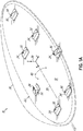
- Figure 1A illustrates a perspective view of an exemplary layout of fitting elements that might be utilized on a mounting surface 12 for mounting the adapter plate 22 utilizing the mounting systems 20 of the invention.
- various mounting systems 20 would each be coupled or fixed to the adaptor plate and would engage a respective fitting 32 as illustrated in Figure 1A .
- such fittings will include spherical bearings or other elements 34 that provide movement of the mounting systems 20 and adapter plate 22 at the various positions or locations on surface 12.
- Mounting system of the invention provides additional movement in certain reference axes 36 as well as adjustability in certain axes as illustrated in Figure 1A and discussed herein.
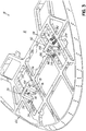
- Figure 2 illustrates a perspective view of one exemplary adapter plate 22 to be mounted using the mounting systems of the invention.
- various of the mounting elements 20 are coupled with plate 22 at multiple positions on the plate 22 that align with the positions of the fittings 32 for securing the plate with the fittings 32 in accordance with embodiments of the invention.
- Figure 2 illustrates different embodiments of mounting systems as discussed herein that may be used at different points or positions on the adapter plate 22 to provide the desired adjustability and freedom of movement.
- several of the elements 20 provide the height (Z-axis) adjustability and freedom of movement of the invention.
- Figure 3 is a more exploded view of a portion of an overall arrangement 10 as illustrated in Figure 2 .
- Figure 3 illustrates one embodiment of a mounting element 50 at one position on plate 22 and another different embodiment of a mounting element 52 at another position on the adapter plate 22 as illustrated.
- the different mounting systems of the invention may be used at different positions on plate 22 to get desired positioning and adjustability of plate 22 on surface 12.
- the mounting systems 50, 52 are each coupled with the adapter plate 22 as shown for varying the height, in the Z-axis of the adapter plate over surface 12 as well as providing for various freedoms of movement with respect to other axes of the system when the adapter plate 22 and systems 24, 26 and radome 30 are installed.
- the mounting systems 50, 52 include various fittings that may be coupled with plate 22 through appropriate mounting holes 54 of the plate and appropriate bolts/fasteners 56.
- the various mounting holes 54 may be laid out as tracks 58, 60 on either side of the mounting systems 50, 52 for positional adjustability of the mounting systems and where they are coupled with respect to the plate.
- Each of the mounting system fittings, as described herein, which couple with the adapter plate 22 or other element that is to be mounted, also adjustably couple with other elements of the mounting system for providing the desired adjustability and freedom of movement of the invention.
- the other elements of the mounting systems 50, 52 as described herein couple with the surface fittings 32, as illustrated in Figures 4A and 4B , with appropriate bolts or other fasteners 62 that extend through openings in the fittings.
- the fittings 32 incorporate spherical bearings and fasteners 62 couple through openings in the spherical bearings 34 as well as through appropriate openings in other elements of the mounting system as discussed herein (See Figure 10C ).
- each of the mounting systems is coupled through a universal joint to fittings 32 and ultimately to surface 12.
- the fittings 32 are secured in an appropriate manner to the surface 12, such as the outer surface of the aircraft, as is conventionally known in the art.
- FIGS 4A and 4B illustrate mounting systems 50, 52 of the invention coupled with the adaptor plate 22 to be mounted, as well as suitable fittings 32 on surface 12.
- the mounting systems may engage the adapter plate 22 or other element from above or below that element.
- mount system 50 has a fitting that mounts to plate 22 at a bottom surface or below the adapter plate
- mounting system 52 has a fitting that mounts to an upper surface or above the adapter plate with appropriate fasteners 56.
- the plurality of apertures 54 along the respective mounting tracks 58, 56 provide adjustability with respect to where the mounting systems 50, 52 engage the adapter plate 22.
- the height of the various points of the adaptor plate are adjusted by being moved up and down in the Z-axis.
- the present invention is not limited to how the mounting system fittings interface with or couple with the adaptor plate and other ways of fixing the adaptor plate with the mounting system may be used so that adjusting the height of the fittings will adjust the height of the adaptor plate or other mounted element.
- adapter plate 22 As illustrated in Figure 2 , various other positions on the adapter plate 22 include appropriate frame elements and mounting apertures for securing antenna systems 24 or communication systems 26 or other elements as appropriate to the plate.
- the adaptor plate 22 illustrated has an aerodynamic shape since it is used on an aircraft.
- the present invention is also not limited to the specific shape or configuration of adapter plate 22 or the systems mounted on the adapter plate 22.
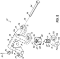
- FIG. 5 is an exploded view of a mounting system 50 in accordance with one embodiment of the invention.
- Mounting system 50 includes a fitting 70 that is configured for coupling with an adapter plate or other element to be mounted to a surface with the mounting system.
- the fitting may be formed of a suitable strong and lightweight metal, such as aluminum.
- Fitting 70 includes opposing side elements 71 that cooperate to form a base 73 for the fitting.
- the base 73 includes one or more tabs or flanges 72 configured for receiving fasteners 56 and engaging with and coupling with the adapter plate to secure the fitting thereto.
- Fitting 70 also includes a bridge portion 74 spanning between the side elements for forming a unitary fitting that engages with other elements of the mounting system for raising and lowering the fitting 70 described herein.
- Mounting system 50 further includes additional elements that sit below the fitting and are adjustable to change the height of the fitting with respect the mounting system.
- a mounting element 76 has a base 78 and a threaded shaft 80 that has external threads 82 thereon. An incremental nut 92 is threaded on the shaft.
- the threaded shaft extends upwardly from the base 78 along an axis 84 as shown in Figure 5 .
- the illustrated mounting element and nut may be formed of a suitable strong and lightweight metal, such as stainless steel.
- the threaded shaft 80 and axis 84 will generally extend in what might be defined as the Z-axis direction (see Figure 1A ). In that way, the mounting system provides adjustment of fitting 74 upwardly and downwardly along the Z-axis which translates into similar movement with respect to a portion of the adapter plate that is mounted to surface 12 through the mounting system 50.
- the mounting element 76 is in the form of a clevis element, and the base 78 of the clevis element 76 embodiment is configured for mounting to the surface 12, such as through engagement with fitting 32 in the illustrated embodiment of the invention.
- the base 78 of the clevis element 76 is generally U-shaped with opposing prongs 77a, 77b having apertures 79a, 79b extending therethrough.
- a pin or bolt extends through the prongs 77a, 77b and respective apertures for coupling-base 78 and the clevis element 76 to a fitting 32.
- the bolt or pin 62 also extends through an appropriate opening in the fitting 32, such as through the opening of a spherical bearing 34 (See Figure 10C ).
- a spherical bearing 34 See Figure 10C .
- the clevis element 76 is coupled to surface 12 and has a freedom of motion provided by spherical bearing 34 that translates to a freedom of movement to the entire mounting system 50 on surface 12.
- the clevis element 76 and threaded shaft 80 may also rotate about the axis of pin or bolt 62.
- the threaded shaft includes an aperture 90 formed therethrough.
- the aperture is formed through the threaded shaft to extend in a direction that is generally perpendicular to the shaft 80 and shaft axis 84.
- the term aperture may refer to a through hole or passage as described that passes through the various elements. In some instances, such apertures of separate elements may then be aligned as described for securing the relative position of the elements with respect to one another.
- the term aperture is also used to describe through holes or passages, such as through the fittings, that have disconnected portions on different sides of the fittings but which are aligned in space along an axis and cooperate to form a generally unitary through hole or passage to receive a pin, bolt or other locking element. Therefore, the term aperture is not meant to be limiting in scope with respect to the invention.
- the aperture 90 is elongated in the direction of the shaft axis 84. That is, with respect to the reference system provided in Figure 1A , the aperture 90 is elongated in the Z-axis direction along the axis of the threaded shaft, as illustrated in Figure 5 and Figures 7A-7B . As described herein, the Z-axis elongation provides a height adjustment feature to the mounting systems in accordance with one feature of the invention.
- mounting system 50 further includes an incremental nut 92 having an opening 94 with internal threads that are configured for being threaded onto shaft 80.
- the incremental nut is configured for rotating on the threaded shaft and moving up and down along the shaft axis 84 (Z-axis) for adjusting the height of the nut 92 on the clevis element 76.
- the fitting 70 is coupled with the incremental nut 92 and threaded shaft.
- the incremental nut has at least one aperture formed therethrough that is also generally perpendicular to the shaft axis 84, when the nut is threaded to the shaft.
- the incremental nut 92 as illustrated in Figure 5 includes a plurality of apertures 100, 102 that extend therethrough across the incremental nut.
- the apertures 100, 102 extend from one side of the nut, through the threaded opening 94 and then out the other side of the incremental nut. That is, portions of the apertures are formed in opposite sides of the nut and align to form effectively the respective aperture for receiving a locking element as discussed herein.
- the apertures 100, 102 extend at an angle with respect to each other in the incremental nut. That is, aperture 100 extends at an angle to the other aperture 102. More specifically, in the illustrated embodiment there are the pair of apertures and they extend at angles wherein one aperture extends at an angle that is generally perpendicular to another aperture. As discussed herein, such apertures 100, 102 provide alignment positions for the incremental nut aperture with the threaded shaft aperture 90 at generally 90 degree or 90° positions around the incremental nut 92.
- the incremental nut is rotated on the threaded shaft 80 of clevis element 76 to move up and down the shaft.
- one of the incremental nut apertures 100, 102 will be aligned with the elongated aperture 90 through shaft 80. That is, at a plurality of rotational positions of the incremental nut along the thread shaft, the apertures 100, 102 will alternately align with aperture 90. Since the apertures are generally perpendicular with each other, there will be alignment of aperture 90 with one or the other of the apertures 100, 102 at 90° increments around the 360° rotation of the nut 92. Upon such alignment, a locking element can engage the aligned apertures and lock the nut at a certain height position on the shaft 80.
- the locking element includes a locking pin or bolt, such as a locking pin 104, that may be positioned to extend through the aligned apertures and through the shaft 80 and incremental nut 92. This prevents further rotation of the nut on the shaft and thus locks the height of the nut and the height of the apertures 100, 102 on the nut. Simultaneously, locking pin 104 extends through apertures 106 formed in the fitting 70 thereby coupling the fitting with the nut. As such, fitting 70 is coupled with incremental nut 92 such that the height of the nut 92 on shift 80 in the direction of the Z-axis 84 will set or determine the height of fitting 70 with the mounting system 50.
- a locking pin or bolt such as a locking pin 104
- clevis element 76 is coupled with both a fitting 32 on surface 12 and the fitting 70, attached to plate 22, this height adjustment, in turn, sets the height of the adapter plate 22 over surface 12. That is, the locking pin 104 passing through the aligned apertures 100, 102 and 90 will prevent the incremental nut from further rotation on shift 80 and thus will secure the incremental nut and any fitting 70 coupled therewith at a selected height on the clevis element 76.
- the height of fitting 70 and adapter plate 22 may be readily and easily adjusted on the Z-axis through rotation of the incremental nut 92 with locking pin 104 removed.
- the locking pin 104 may be inserted to secure the height of incremental nut and the height of fitting 70 and plate 22 on the surface 12.
- the plurality of apertures 100, 102 formed in incremental nut 92 provide adjustment positions at quarter turn or 90° intervals or positions around the incremental nut. That is, the incremental nut 92 may be adjusted in increments by rotation of incremental nut 92 at 90° increments to achieve alignment of a respective aperture 100, 102 with aperture 90.
- the height adjustment achieved for each incremental turn or 90° rotation of the nut 92 will be determined by the thread count of the threads used to couple threaded shaft 80 and incremental nut 92.
- two apertures 100, 102 positioned generally perpendicular to each other provide positions at 90° increments around incremental nut as discussed.
- the invention might also incorporate additional apertures, such as at 45° increments or positions around the nut 92 (1/8 th turn increments).
- additional apertures such as at 45° increments or positions around the nut 92 (1/8 th turn increments).
- two additional apertures like apertures 100, 102, would be formed through the side of the nut 92.
- the present invention is not limited to having just two apertures through nut 92 for achieving 90° increments of rotation and other smaller increments may be used.
- just a single aperture might be used and the adjustability might be in 180° rotational increments(1 ⁇ 2 turn increments) achieved by aperture alignment.
- Locking pin 104 might be secured in the fitting 70 by an appropriate cap nut 112 and cotter pin or split pin 114 that extends through a receiving aperture 116 formed in locking pin 104.
- the plate 22 with fitting 70 coupled thereto may be positioned so that the fitting 70 overlies the clevis element 76 and incremental nut 92.
- the incremental nut 92 is rotated appropriately until a height position is reached where one of the apertures 100, 102 aligns with aperture 90 in the threaded shaft 80. Then, locking pin 104 may be inserted to secure fitting 70 and the plate 22 with the mounting system 50 at a suitable height above surface 12.
- the feature of mounting system 50 provides and adjustment range in the Z-axis 84 for quick and proper mounting of the plate at the position on the plate where the mounting system is located.
- the movement and Z-axis adjustment is illustrated by reference arrows 120 illustrated in Figure 7A .
- the range of adjustment in height is provided by the length of the elongated aperture 90 along the shaft axis. As the incremental nut moves up and down the shaft of the clevis element, there will be certain upper and lower positions wherein the apertures 100, 102 will no longer align with elongated aperture 90 to receive a locking pin 104.
- the aperture 90 formed in the threaded shaft 80 is elongated in the direction of the shaft axis or Z-axis 84, and as such, the elongated aperture 90 has a length dimension in the Z-axis Lz.
- the length dimension Lz of the elongated aperture is greater than the diameter of the corresponding apertures 100, 102 the incremental nut 92 as well as locking pin 104.
- the height adjustment of the incremental nut 92 and fitting 70 along the Z-axis 84 and shaft 80 is provided over a height range as dictated by the length Lz of the elongated aperture 90.
- the apertures 100, 102 move up and down shaft 80 and still provide for aperture alignment at various height positions along shaft 80 until the ends of the elongated aperture 90 are reached and any further incremental turns will not provide for full alignment of an aperture 100, 102 with the aperture 90 for passing locking pin 104 through the aligned apertures.
- incremental nut 92 is rotated to provide alignment wherein the apertures 100, 102 are aligned with aperture 90 so that the aperture may be engaged with locking pin 104 and fitting 70 at a selected height.
- rotation of the nut 92 past that maximum position will not result in alignment of the apertures to allow the locking pin 104 to pass through the apertures.
- there will be a lower height limit at the bottom end of the aperture 90 dictating the lowest Z-axis height for the nut and the fitting 70.
- the dimension of the elongation Lz with respect to aperture 90 may be in the range of 2 millimeters (mm) - 6 millimeters (mm) and for providing a range of overall height adjustment for fitting 70 and adapter plate 22. In that way, the mounting system effectively provides a range of movement that may be essentially ⁇ 1 mm up to ⁇ 3 mm between the minimum and maximum height adjustments.
- the invention provides a simple incremental adjustment of the mounting height for fitting 70 and thus provides a quick and easy height adjustment for certain points of the adapter plate without requiring shims or other structures between the plate 22 mounting structures and surface 12. This provides a significant savings in time and complexity in mounting the plate element.
- the mounting system 50 also provides additional freedom of movement for the fitting 70 and plate 22 along the Y-axis or axis 110 as illustrated in Figure 7A .
- the fitting may slide laterally along the axis 110 of locking pin 104 or the Y-axis when mounted. Still further, the fitting may rotate about that same Y-axis as shown as fitting rotates on or about the locking pin 104. This provides further movement and adaptability of the invention once it is mounted to adapt to the expansion and contraction of the surface 12, such as on an aircraft surface, after the plate is mounted.
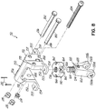
- FIG 8 illustrates an exploded view of a mounting system 52 in accordance with another embodiment the invention.
- Mounting system 52 includes a mounting element 120 having a base 122 and a threaded shaft 124 extending from the base along an axis 126. As with mounting system 50, the shaft generally will extend along the reference Z-axis when mounting system 52 is coupled with an appropriate fitting on surface 12.
- the illustrated mounting element 120 is in the form of a clevis element that is also generally u-shaped with opposing prongs 130a, 130b having apertures 132a, 132b extending therethrough.
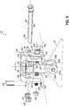
- a pin or bolt 62 extends through the prongs 130a, 130b and respective apertures for coupling the base 122 and the overall clevis element 122 to a fitting, such as fitting 32, as illustrated in Figure 9 .
- the pin or bolt 62 also extends through an appropriate opening in the fitting 32, such as through the opening of a spherical bearing 34 (see Figure 10C ).
- the clevis element 120 is coupled to surface 12 and has a freedom of motion provided by spherical bearing 34.
- Clevis element 120 and shaft 124 also rotate about the axis of pin or bolt 62.
- the threaded shaft124 includes external threads 134 that match with internal threads in hole 136 of an incremental nut 140 that is configured for rotating on shaft 124.
- the incremental nut 140 is configured for rotating on the threaded shaft and moving up and down along the shaft axis 126 for adjusting the height of a nut on the clevis element 120 and adjusting the height of a fitting 150.
- the fitting might be made of aluminum and the clevis element and incremental nut of stainless steel.
- the mounting system 52 also includes a fitting 150 that is configured for coupling with an adapter plate or other element to be mounted with the mounting system 52.
- Fitting 150 is configured to be mounted on a top surface of the mounting plate 22 is illustrated in Figure 3 .
- mounting system 50 has a fitting configured for mounting to a bottom surface of the adapter plate.
- Fitting 50 maybe coupled with an adapter plate 22 or some other element in a number of different ways and thus the invention is not limited to how the fitting of mounting system 52 might engage and couple with the adapter plate.
- Fitting 150 generally includes a base 151 that includes two opposing side elements 152 that each have one of more flanges 154 extending therefrom.
- Fitting 150 also includes a bridge portion 156 that couples with the side elements 152 of the base 151 and engages with other elements of the mounting system 52 for raising and lowering the fitting 150 as described herein.
- the flanges 154 may be secured to the adapter plate 22 with one or more fasteners 56 extending through appropriate openings 155 in the flanges.
- the threaded shaft 124 when the mounting system 52 is coupled with a fitting 32, the threaded shaft 124 would generally extend in what might be defined as the Z-axis of direction (see Figure 1A ) and that way, mounting system provides adjustment of the fitting 74 upwardly and downwardly along a Z-axis 126 which translates into a similar movement with respect to a portion of the adapter plate or other element that is mounted to surface 12 through the mounting system 52.
- the fitting 150 and incremental nut each include at least one aperture formed therethrough.
- the apertures are aligned for receiving one or more locking elements, such as locking pins, that pass through the aligned apertures for securing the incremental nut with the fitting. More specifically, an incremental nut aperture and a fitting aperture would be aligned at one of a plurality of rotational positions of the incremental nut along the threaded shaft.
- the incremental nut includes apertures 160, 162 extending on opposite sides of the incremental nut and on either side of the threaded opening 136.
- the apertures 160, 162 are formed parallel to each other on opposite sides of the nut and opening 136.
- the apertures 160, 162 act together and secure the fitting with nut 140 as described herein.
- the incremental nut 140 also includes another pair of parallel apertures 164, 166 each on an opposite side of the incremental nut and on either side of the threaded opening 136.
- the pair of apertures 164, 166 are oriented essentially perpendicular to the other pair of parallel apertures 160, 162 on the incremental nut.
- the fitting 150 includes corresponding apertures 170, 172 that may align with a respective pair of apertures 160, 162 or 164, 166 on the incremental nut 140, depending upon the rotation of the incremental nut along the threaded shaft 124.
- the perpendicular pairs of apertures 160, 162 and 164, 166 provide alignment of the incremental nut apertures with the respective fitting apertures 170, 172 generally at 90° positions around the incremental nut. That is, as the incremental nut is rotated and nut apertures are aligned with apertures 170 and 172, the nut may be rotated 90° and again aligned with the apertures 170, 172.
- Apertures 160, 162 might be aligned at one rotational position with apertures 170 and 172, and then apertures 164, 166 might be aligned at another rotational position that is 90° for the first position.
- Respective locking pins 180, 182 pass through the aligned apertures 170, 172 and the respective incremental nut apertures, such as either aperture pair 160, 162 or aperture pair 164, 166.
- reference to an aperture 170 or 172 refers to the disconnected portions of a respective aperture that are positioned on either side of the fitting element and are aligned in space to form a single aperture, as illustrated in Figure 8 .
- reference numerals 170 and 172 refer singularly to the various portions of the aperture that allow respective locking pins 180, 182 to pass through the entire fitting and through the aligned apertures in the incremental nut 140.
- incremental nut 140 is configured for rotating on the threaded shaft and moving up and down along the shaft axis for adjusting the height of the nut, on the clevis element. Because the incremental nut and fitting are coupled together, the variation of the height of the nut also varies the height of the fitting 150 as illustrated by reference arrows 190 in Figure 10A .
- the clevis element 120 has an aperture 200 formed through the base 122.
- the fitting has a corresponding aperture 202 formed in the base 151 and particularly through the side elements 152 of the base of the fitting.
- Aperture 200 aligns with aperture 202 formed in the base 151 of the fitting 150 when the fitting is positioned with the incremental nut and secured therewith using locking pins 180, 182.
- the apertures 200 and 202 are aligned for receiving a bolt 204 that extends through the fitting base aperture 202 as illustrated in Figure 8 and also through the clevis element base aperture 200 for further securing the fitting with the clevis element.
- the fitting base aperture 202 is elongated in the Z-axis direction, which is essentially is the direction of the shaft axis 126 making reference to the Z-direction is defined in Figure 1A .
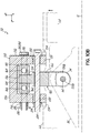
- the elongated aperture has a length Lz as illustrated in Figures 10A and 10C . That is, the aperture 202 is elongated in the direction of height adjustment similar to the elongated aperture 90 of mounting system 50.
- the bolt 204 is threaded as is the aperture 200.
- the range of height adjustment for the mounting system is determined by the elongation dimension Lz of the aperture 202.
- the elongation allows the nut 140 and the fitting 150 to move in the Z-axis with respect to the bolt 204 a certain distance and still achieve an alignment between the aperture 200 and bolt 204 and the aperture 202. This thereby allows incremental height adjustments of the fitting 150 based upon the rotation of the incremental nut 140.
- the range of height adjustment and alignment before the fitting aperture 202 would no longer align with aperture 200 depends upon the elongated length Lz of aperture 202.
- the length Lz or effective height of the elongated aperture 202 as illustrated in Figures 10A and 10C provides an upper and lower limit with respect to the incremental and rotational height adjustment of the incremental nut 140 and fitting 150.
- the incremental nut is illustrated essentially at its highest position wherein bolt 204 engages the bottom of the elongated aperture 202.
- the Lz with respect to aperture 202 may be in the range of 2 mm - 6 mm and provide an overall height adjustment for fitting 150 and adapter plate 22 which is raised and lowered along with the fitting 150 as noted by reference arrow 210 in Figure 10B .
- incremental nut 140 When assembling the mounting system 52, incremental nut 140 may be coupled with shaft 124 of the clevis element and fitting 150 may be coupled with the clevis element through bolt 204 and the apertures 200, 202. Incremental nut 140 may be rotated in incremental fashion to a desired height. The fitting can move up and down with respect to bolt 204 due to the aperture 202. Incremental nut 140 may then be coupled with the fitting 150 through the appropriate locking pins 180, 182 extending through the aligned apertures of the fitting 150 and the respective aperture pairs in the incremental nut 140. The locking pins 180, 182 also prevent further rotation and lock the height of the nut
- the locking pins 180, 182 may be removed and the incremental nut maybe rotated to move up or down on shaft 124 for varying the height.
- the locking pins 180 and 182 may then be reinserted to secure the incremental nut with the fitting and also to lock the height of the incremental nut 140 on shaft 124 and thus lock the height of the overall mounting system 52 with respect to surface 12.
- the incremental nut 140 may be adjusted in 90° rotational increments for alignment of the respective apertures 160, 162 or 164, 166 with the fitting apertures 170, 172.
- the height adjustment for each incremental rotation of the nut will again be determined by the thread count of threads used a couple shaft 124 and incremental nut 140.
- two apertures pairs are positioned generally perpendicular to each other to provide positions at 90° increments around incremental nut as discussed.
- the invention might also incorporate additional apertures or pairs of apertures, such as at 45° increments or positions around the nut 92.
- additional apertures similar to apertures 160-166 might be formed through the side of the nut 140.
- the present invention is not limited to having just two aperture pairs through nut 92 for achieving 90° increments of rotation and other smaller increments may be used.
- just a single aperture pair might be used and the adjustability might be in 180° rotational increments achieved by aperture alignment.
- the locking pins might be secured with the fitting and through the appropriate aligned apertures with appropriate cap nuts 210 and cotter pins or split pins 212 that extends through a receiving apertures 216 formed in locking pins 180, 182.
- Bolt 204 will be threaded into the threaded aperture 200 and provides Y-axis adjustment to the fitting 150 with respect to the clevis element 120. Rotation of the threaded bolt 204, moves the bolt right or left with respect to the threaded aperture 200 in the clevis element and thus will move the fitting 150 left or right along the Y-axis. Once the desired position is achieved, the threaded bolt may be capped with the threaded cap-nut 214 as illustrated in Figure 8 to lock the position of the fitting in the Y-axis.
- the portion or point of adapter plate is locked in the Y-axis and Z-axis.
- the parallel bolts 180, 182 will generally prevent rotation about that same Y-axis. In that way, the mounting system 52 does not provide rotational movement on the Y-axis as does the system of mounting system 50.
- the mounting systems 50, 52 as described herein provide desired adjustment of the height of adapter plate 22 or some other element mounted to surface 12 using the mounting systems.
- the height adjustable long Z-axis may be readily and incrementally achieved by rotation of the incremental nut elements of each of mounting systems.
- the incremental nuts may be locked into position with appropriate locking elements coupled with the incremental nuts and fitting elements to thereby lock the height of the fitting element and in turn the height of the adapter plate or other mounted element with respect to surface 12.
- the mounting systems further provide some linear and rotational freedom of movement along the Y-axis as disclosed herein in accordance with certain embodiments of the invention.
Landscapes
- Engineering & Computer Science (AREA)
- General Engineering & Computer Science (AREA)
- Mechanical Engineering (AREA)
- Aviation & Aerospace Engineering (AREA)
- Physics & Mathematics (AREA)
- Astronomy & Astrophysics (AREA)
- General Physics & Mathematics (AREA)
- Remote Sensing (AREA)
- Connection Of Plates (AREA)
- Pivots And Pivotal Connections (AREA)
Description
- The present invention relates generally to mounting systems and specifically to a system for mounting antenna systems and electronic systems to a surface of an aircraft.
- In avionics, various communications systems are used in an aircraft for performance of the aircraft. Such aircraft mounted communication systems often involve and use various electronics systems and antenna elements for communicating with ground-based or satellite-based communication systems.
- To that end, the antenna elements that are used for such communication systems are usually mounted on the outside of the plane, such as to a fuselage surface where they are exposed, in use, to outside elements in flight. As such, the system electronics and antenna elements as well as other outside airframe equipment (OAE) must be securely mounted to the plane and usually covered with a radome or cover of some kind for protection from the elements and in flight debris, such as birds. For mounting such elements and OAE systems, usually an adaptor plate or frame of some kind is used and the antenna elements and other electronic elements of the systems are mounted to the adaptor plate. The adaptor plate or frame is then mounted to the surface of the aircraft fuselage in an appropriate position. One such adaptor plate is the CarlisleIT ARINC 791 plate from Carlisle Interconnect Technologies, Inc.
- As may be appreciated, the outside surface or skin of an aircraft is not always a smooth and consistent surface due to its construction from various sections that are coupled together and secured onto the aircraft frame. Usually a lightweight metal such as aluminum or alloys of aluminum are used. Furthermore, the aircraft and outside aircraft surface are subject to significant temperature variations that cause the fuselage to expand and contract in different ways during usage that are not always consistent.
- Therefore, such considerations must be taken into account when mounting antenna and electronic system adaptor plates to aircraft. The adaptor plates must be affixed properly so that they lie tightly against the surface. Furthermore, they must be able to move and adjust as the surface of the plane expands and contracts in order to reduce fatigue of the plates. In the past, universal joints have been utilized for mounting or installing such adaptor plates to provide some movement and adjustability as the adaptor plate is installed. However, even with such elements, in order to achieve proper mounting alignment and height (z-axis) adjustments, installers have to use shims, mechanical spacers and other additional elements between the adaptor plates and aircraft surface. As may be appreciated, because of different aircraft surfaces and variables, different z-axis scenarios are often encountered during installation. Furthermore, to achieve alignment and installation there may be a certain amount of pre-load on some of the mounting elements that may result in part fatigue. As may be appreciated, such necessities and concerns make the mounting process more difficult as well as slow the process down significantly.
- Accordingly, there is a need to improve the process of installation of adaptor plates and electronic/antenna systems to an aircraft outside surface. There is further a need to standardize or simplify the installation process for such outside adaptor plates and systems.
-
US 2360626 relates to a screw nut which is adapted to be interlocked with a screw bolt so as to prevent easy separation of the same, and more particularly to a castellated screw nut which is adapted to be secured against turning on a bolt by driving a cotter pin through a pair of notches in the outer end of the nut and through a transverse hole in the bolt. - The invention is defined by the claims.
- A mounting system for mounting an aircraft element to a surface includes, in one embodiment, a mounting element having a base and a threaded shaft extending from the base along an axis. The base is configured for mounting to the surface, such as the surface of an aircraft. An aperture is formed through the threaded shaft and is generally perpendicular to the shaft axis and is elongated in the direction of the shaft axis. An incremental nut is configured for rotating on the threaded shaft and moving up and down along the shaft axis for adjusting the height of the nut on the mounting element. The incremental nut has apertures formed therethrough generally perpendicular to the shaft axis and an incremental nut aperture and threaded shaft aperture are aligned at a plurality of rotational positions along the threaded shaft. A locking element passes through the aligned incremental nut aperture and threaded shaft aperture for securing the incremental nut at a selected height. A fitting is coupled with the incremental nut and further configured for coupling with an aircraft element to mount the aircraft element to the surface at a selected height above the surface.
- In another embodiment, a mounting system includes a mounting element having a base and a threaded shaft extending from the base along an axis. The base is configured for mounting to a surface and an incremental nut is configured for rotating on the threaded shaft and moving up and down along the shaft axis for adjusting the height of the nut on the mounting element. The incremental nut has apertures formed therethrough. A fitting is configured for coupling with an aircraft element to mount the aircraft element to the surface at a selected height above the surface. The fitting includes an aperture formed therethrough where the incremental nut aperture and fitting aperture are aligned at a plurality of rotational positions of the incremental nut along the threaded shaft. A locking element passes through the aligned incremental nut aperture and fitting aperture for securing the incremental nut with the fitting at a selected height on the mounting element.
- The accompanying drawings, which are incorporated in and constitute a part of this specification, illustrate embodiments of the invention and together with the detailed description given below, serve to explain various aspects of the invention.
-
Fig. 1 is a cross sectional view of a mounting systems in accordance with the invention mounting an adaptor plate and systems to a surface. -
Fig. 1A is a plan view of a surface and fittings for mounting an element using embodiments of mounting systems in accordance with the invention. -
Fig. 2 is a plan view of an adaptor plate to be mounted to a surface using embodiments of mounting systems in accordance with the invention. -
Fig. 3 is an enlarged partial plan view of an adaptor plate as inFigure 2 to be mounted to a surface using embodiments of mounting systems in accordance with the invention. -
Fig. 4A is a front view of an adaptor plate as inFigure 2 to be mounted to a surface using embodiments of mounting systems in accordance with the invention. -
Fig. 4B is an exploded front view of an adaptor plate as inFigure 4A to be mounted to a surface using embodiments of mounting systems in accordance with the invention. -
Fig. 5 is an exploded perspective view of a mounting system in accordance with an embodiment of the invention. -
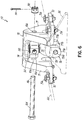
Fig. 6 is an assembled perspective view of a mounting system in accordance with the embodiment of the invention illustrated inFig. 5 . -
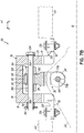
Fig. 7A is a cross sectional view of a mounting system in accordance with the embodiment of the invention illustrated inFig. 5 . -
Fig. 7B is another cross sectional view of a mounting system in accordance with the embodiment of the invention illustrated inFig. 5 . -
Fig. 7C is another cross sectional view of a mounting system in accordance with the embodiment of the invention illustrated inFig. 5 . -
Fig. 8 is an exploded perspective view of a mounting system in accordance with an embodiment of the invention. -
Fig. 9 is an assembled perspective view of a mounting system in accordance with the embodiment of the invention illustrated inFig. 8 . -
Fig. 10A is a cross sectional view of a mounting system in accordance with the embodiment of the invention illustrated inFig. 8 . -
Fig. 10B is another cross sectional view of a mounting system in accordance with the embodiment of the invention illustrated inFig. 8 . -
Fig. 10C is another cross sectional view of a mounting system in accordance with the embodiment of the invention illustrated inFig. 8 . -
Figure 1 illustrates a front view of a mounting arrangement using the mounting systems of the present invention for mounting antenna systems and electronic communication systems to a surface, such as an aircraft surface. Referring toFigure 1 , the mountingarrangement 10 for mounting a system, such as an antenna system, is shown. The mountingarrangement 10 is mounted onto asurface 12, such as the outer surface of the fuselage or wing of an aircraft. In accordance with one embodiment invention, thearrangement 10 uses a plurality of mountingsystems 20 of the invention that couple with theelement 22, such as an adaptor plate, and also couple with a series of fittings 16 on thesurface 12. The fittings 16 may include universal bearings for movement of the various mountingsystems 20 with respect to the fittings 16. The fittings, in turn, are attached to surface 12 and thus provide some movement of thesystems 20 and the mountedelement 22 on that surface. - The mounting
systems 20 of the invention are coupled withelement 22 and are coupled with thefittings 32 at a plurality of positions onsurface 12. Therefore, the invention may provide the desired adjustability and freedom of movement at several positions on the mountedelement 22. In one example, theelement 22 that is to be mounted to surface 12, such as an adaptor plate or frame, may contain one ormore antenna systems 24 and/orother communications systems 26 for use by an aircraft.Such antenna systems 24 andcommunications systems 26 may include a variety of different components. The present invention is not limited to the systems that would be mounted using the invention. Furthermore, although anadapter plate 22 or other frame is described herein for being secured to thesurface 12, such as an aircraft surface, other different elements may be mounted to other surfaces using the inventive mounting systems. Thus, the mounting systems of the invention are not limited to mounting aircraft elements to an aircraft surface but may be used for other mounting arrangements wherein the adjustments and freedom of movement provided by the invention are desired. Generally, with aircraft systems, for the purpose of protection, aradome 30 or some other cover is utilized and is coupled with theadapter plate 22 to protect thesystems Figure 1 . -
Figure 1A illustrates a perspective view of an exemplary layout of fitting elements that might be utilized on a mountingsurface 12 for mounting theadapter plate 22 utilizing the mountingsystems 20 of the invention. Specifically, various mountingsystems 20 would each be coupled or fixed to the adaptor plate and would engage arespective fitting 32 as illustrated inFigure 1A . Generally, such fittings will include spherical bearings orother elements 34 that provide movement of the mountingsystems 20 andadapter plate 22 at the various positions or locations onsurface 12. Mounting system of the invention provides additional movement incertain reference axes 36 as well as adjustability in certain axes as illustrated inFigure 1A and discussed herein. -
Figure 2 illustrates a perspective view of oneexemplary adapter plate 22 to be mounted using the mounting systems of the invention. As illustrated inFigure 2 , various of the mountingelements 20 are coupled withplate 22 at multiple positions on theplate 22 that align with the positions of thefittings 32 for securing the plate with thefittings 32 in accordance with embodiments of the invention.Figure 2 illustrates different embodiments of mounting systems as discussed herein that may be used at different points or positions on theadapter plate 22 to provide the desired adjustability and freedom of movement. In accordance with one feature of the invention, several of theelements 20 provide the height (Z-axis) adjustability and freedom of movement of the invention. Different height adjustments thus allow for the general rotational positioning of theadapter plate 22 about theX-axis 39 as illustrated by reference arrow 40 (SeeFigure 1A ). Other mounting elements orsystems 21 might be utilized in other areas of theadapter plate 22 in addition to the mounting systems of the invention but may not provide the adjustability of the mounting elements of the invention. Embodiments of the exemplary mountingelements 20 as disclosed herein have different adjustability and freedoms of motion and thus have somewhat different constructions. -
Figure 3 is a more exploded view of a portion of anoverall arrangement 10 as illustrated inFigure 2 . Specifically,Figure 3 illustrates one embodiment of a mountingelement 50 at one position onplate 22 and another different embodiment of a mountingelement 52 at another position on theadapter plate 22 as illustrated. The different mounting systems of the invention may be used at different positions onplate 22 to get desired positioning and adjustability ofplate 22 onsurface 12. To that end, the mountingsystems adapter plate 22 as shown for varying the height, in the Z-axis of the adapter plate oversurface 12 as well as providing for various freedoms of movement with respect to other axes of the system when theadapter plate 22 andsystems radome 30 are installed. - More specifically, the mounting
systems plate 22 through appropriate mountingholes 54 of the plate and appropriate bolts/fasteners 56. As illustrated in the figures, the various mountingholes 54 may be laid out astracks systems adapter plate 22 or other element that is to be mounted, also adjustably couple with other elements of the mounting system for providing the desired adjustability and freedom of movement of the invention. The other elements of the mountingsystems surface fittings 32, as illustrated inFigures 4A and4B , with appropriate bolts orother fasteners 62 that extend through openings in the fittings. In one use of the mounting systems of the invention, thefittings 32 incorporate spherical bearings andfasteners 62 couple through openings in thespherical bearings 34 as well as through appropriate openings in other elements of the mounting system as discussed herein (SeeFigure 10C ). In that way, each of the mounting systems is coupled through a universal joint tofittings 32 and ultimately to surface 12. Thefittings 32 are secured in an appropriate manner to thesurface 12, such as the outer surface of the aircraft, as is conventionally known in the art. -
Figures 4A and4B illustrate mountingsystems adaptor plate 22 to be mounted, as well assuitable fittings 32 onsurface 12. As is illustrated, the mounting systems may engage theadapter plate 22 or other element from above or below that element. For example, as illustrated inFigures 4A and4B ,mount system 50 has a fitting that mounts to plate 22 at a bottom surface or below the adapter plate, whereas mountingsystem 52 has a fitting that mounts to an upper surface or above the adapter plate withappropriate fasteners 56. The plurality ofapertures 54 along the respective mounting tracks 58, 56 provide adjustability with respect to where the mountingsystems adapter plate 22. As the height of the fittings of the mounting systems are adjusted, the height of the various points of the adaptor plate are adjusted by being moved up and down in the Z-axis. The present invention is not limited to how the mounting system fittings interface with or couple with the adaptor plate and other ways of fixing the adaptor plate with the mounting system may be used so that adjusting the height of the fittings will adjust the height of the adaptor plate or other mounted element. - As illustrated in
Figure 2 , various other positions on theadapter plate 22 include appropriate frame elements and mounting apertures for securingantenna systems 24 orcommunication systems 26 or other elements as appropriate to the plate. Theadaptor plate 22 illustrated has an aerodynamic shape since it is used on an aircraft. The present invention is also not limited to the specific shape or configuration ofadapter plate 22 or the systems mounted on theadapter plate 22. - Turning now to the mounting systems,
Figure 5 is an exploded view of a mountingsystem 50 in accordance with one embodiment of the invention. Mountingsystem 50 includes a fitting 70 that is configured for coupling with an adapter plate or other element to be mounted to a surface with the mounting system. The fitting may be formed of a suitable strong and lightweight metal, such as aluminum. Fitting 70 includes opposingside elements 71 that cooperate to form abase 73 for the fitting. Thebase 73 includes one or more tabs orflanges 72 configured for receivingfasteners 56 and engaging with and coupling with the adapter plate to secure the fitting thereto. Fitting 70 also includes abridge portion 74 spanning between the side elements for forming a unitary fitting that engages with other elements of the mounting system for raising and lowering the fitting 70 described herein. - Mounting
system 50 further includes additional elements that sit below the fitting and are adjustable to change the height of the fitting with respect the mounting system. A mountingelement 76 has abase 78 and a threadedshaft 80 that hasexternal threads 82 thereon. Anincremental nut 92 is threaded on the shaft. The threaded shaft extends upwardly from thebase 78 along anaxis 84 as shown inFigure 5 . The illustrated mounting element and nut may be formed of a suitable strong and lightweight metal, such as stainless steel. Generally, when the mounting system is mounted as illustrated inFigures 1A and2 , the threadedshaft 80 andaxis 84 will generally extend in what might be defined as the Z-axis direction (seeFigure 1A ). In that way, the mounting system provides adjustment of fitting 74 upwardly and downwardly along the Z-axis which translates into similar movement with respect to a portion of the adapter plate that is mounted to surface 12 through the mountingsystem 50. - Referring to
Figures 6 - 7C , the mountingelement 76 is in the form of a clevis element, and thebase 78 of theclevis element 76 embodiment is configured for mounting to thesurface 12, such as through engagement with fitting 32 in the illustrated embodiment of the invention. Thebase 78 of theclevis element 76 is generally U-shaped with opposingprongs 77b having apertures prongs base 78 and theclevis element 76 to a fitting 32. The bolt or pin 62 also extends through an appropriate opening in the fitting 32, such as through the opening of a spherical bearing 34 (SeeFigure 10C ). In that way, theclevis element 76 is coupled to surface 12 and has a freedom of motion provided byspherical bearing 34 that translates to a freedom of movement to theentire mounting system 50 onsurface 12. Theclevis element 76 and threadedshaft 80 may also rotate about the axis of pin orbolt 62. - In accordance with one aspect of the invention, the threaded shaft includes an
aperture 90 formed therethrough. The aperture is formed through the threaded shaft to extend in a direction that is generally perpendicular to theshaft 80 andshaft axis 84. As used herein, the term aperture may refer to a through hole or passage as described that passes through the various elements. In some instances, such apertures of separate elements may then be aligned as described for securing the relative position of the elements with respect to one another. The term aperture is also used to describe through holes or passages, such as through the fittings, that have disconnected portions on different sides of the fittings but which are aligned in space along an axis and cooperate to form a generally unitary through hole or passage to receive a pin, bolt or other locking element. Therefore, the term aperture is not meant to be limiting in scope with respect to the invention. - In accordance with another aspect of the invention, the
aperture 90 is elongated in the direction of theshaft axis 84. That is, with respect to the reference system provided inFigure 1A , theaperture 90 is elongated in the Z-axis direction along the axis of the threaded shaft, as illustrated inFigure 5 andFigures 7A-7B . As described herein, the Z-axis elongation provides a height adjustment feature to the mounting systems in accordance with one feature of the invention. - Referring again to
Figure 5 , mountingsystem 50 further includes anincremental nut 92 having anopening 94 with internal threads that are configured for being threaded ontoshaft 80. In that way, the incremental nut is configured for rotating on the threaded shaft and moving up and down along the shaft axis 84 (Z-axis) for adjusting the height of thenut 92 on theclevis element 76. - For providing height adjustment of fitting 70 and thus the
adapter plate 22, the fitting 70 is coupled with theincremental nut 92 and threaded shaft. To that end, the incremental nut has at least one aperture formed therethrough that is also generally perpendicular to theshaft axis 84, when the nut is threaded to the shaft. Specifically, in the illustrated embodiment, theincremental nut 92 as illustrated inFigure 5 includes a plurality ofapertures apertures opening 94 and then out the other side of the incremental nut. That is, portions of the apertures are formed in opposite sides of the nut and align to form effectively the respective aperture for receiving a locking element as discussed herein. - In one embodiment of the invention, the
apertures aperture 100 extends at an angle to theother aperture 102. More specifically, in the illustrated embodiment there are the pair of apertures and they extend at angles wherein one aperture extends at an angle that is generally perpendicular to another aperture. As discussed herein,such apertures shaft aperture 90 at generally 90 degree or 90° positions around theincremental nut 92. - More specifically, the incremental nut is rotated on the threaded
shaft 80 of cleviselement 76 to move up and down the shaft. At certain positions of rotation, one of theincremental nut apertures elongated aperture 90 throughshaft 80. That is, at a plurality of rotational positions of the incremental nut along the thread shaft, theapertures aperture 90. Since the apertures are generally perpendicular with each other, there will be alignment ofaperture 90 with one or the other of theapertures nut 92. Upon such alignment, a locking element can engage the aligned apertures and lock the nut at a certain height position on theshaft 80. In the illustrated embodiments, the locking element includes a locking pin or bolt, such as alocking pin 104, that may be positioned to extend through the aligned apertures and through theshaft 80 andincremental nut 92. This prevents further rotation of the nut on the shaft and thus locks the height of the nut and the height of theapertures pin 104 extends throughapertures 106 formed in the fitting 70 thereby coupling the fitting with the nut. As such, fitting 70 is coupled withincremental nut 92 such that the height of thenut 92 onshift 80 in the direction of the Z-axis 84 will set or determine the height of fitting 70 with the mountingsystem 50. Since cleviselement 76 is coupled with both a fitting 32 onsurface 12 and the fitting 70, attached to plate 22, this height adjustment, in turn, sets the height of theadapter plate 22 oversurface 12. That is, the lockingpin 104 passing through the alignedapertures shift 80 and thus will secure the incremental nut and any fitting 70 coupled therewith at a selected height on theclevis element 76. - As such, using the mounting
element 50, the height of fitting 70 andadapter plate 22 may be readily and easily adjusted on the Z-axis through rotation of theincremental nut 92 with lockingpin 104 removed. Once the desired height of the nut is achieved, the lockingpin 104 may be inserted to secure the height of incremental nut and the height of fitting 70 andplate 22 on thesurface 12. In accordance with one feature of the invention, the plurality ofapertures incremental nut 92 provide adjustment positions at quarter turn or 90° intervals or positions around the incremental nut. That is, theincremental nut 92 may be adjusted in increments by rotation ofincremental nut 92 at 90° increments to achieve alignment of arespective aperture aperture 90. The height adjustment achieved for each incremental turn or 90° rotation of thenut 92 will be determined by the thread count of the threads used to couple threadedshaft 80 andincremental nut 92. - In the illustrated embodiment of the invention, two
apertures apertures nut 92. As such, the present invention is not limited to having just two apertures throughnut 92 for achieving 90° increments of rotation and other smaller increments may be used. Similarly, just a single aperture might be used and the adjustability might be in 180° rotational increments(½ turn increments) achieved by aperture alignment. - Locking
pin 104 might be secured in the fitting 70 by anappropriate cap nut 112 and cotter pin or splitpin 114 that extends through a receivingaperture 116 formed in lockingpin 104. Referring toFigure 6 , when mounting theadapter plate 22 ontosurface 12, theplate 22 with fitting 70 coupled thereto may be positioned so that the fitting 70 overlies theclevis element 76 andincremental nut 92. For adjusting the height of mounting system, theincremental nut 92 is rotated appropriately until a height position is reached where one of theapertures aperture 90 in the threadedshaft 80. Then, lockingpin 104 may be inserted to secure fitting 70 and theplate 22 with the mountingsystem 50 at a suitable height abovesurface 12. - The feature of mounting
system 50 provides and adjustment range in the Z-axis 84 for quick and proper mounting of the plate at the position on the plate where the mounting system is located. The movement and Z-axis adjustment is illustrated byreference arrows 120 illustrated inFigure 7A . The range of adjustment in height is provided by the length of theelongated aperture 90 along the shaft axis. As the incremental nut moves up and down the shaft of the clevis element, there will be certain upper and lower positions wherein theapertures elongated aperture 90 to receive alocking pin 104. More specifically, as noted herein, theaperture 90 formed in the threadedshaft 80 is elongated in the direction of the shaft axis or Z-axis 84, and as such, theelongated aperture 90 has a length dimension in the Z-axis Lz. In accordance with the invention, the length dimension Lz of the elongated aperture is greater than the diameter of the correspondingapertures incremental nut 92 as well as lockingpin 104. As such, the height adjustment of theincremental nut 92 and fitting 70 along the Z-axis 84 andshaft 80 is provided over a height range as dictated by the length Lz of theelongated aperture 90. Accordingly, by incremental turns of theincremental nut 92 theapertures shaft 80 and still provide for aperture alignment at various height positions alongshaft 80 until the ends of theelongated aperture 90 are reached and any further incremental turns will not provide for full alignment of anaperture aperture 90 for passing lockingpin 104 through the aligned apertures. - Referring to
Figures 7B and7C ,incremental nut 92 is rotated to provide alignment wherein theapertures aperture 90 so that the aperture may be engaged withlocking pin 104 and fitting 70 at a selected height. Depending upon the length Lz of the elongated aperture, there will be a maximum height position for lockingpin 104 as illustrated inFigure 7C . As noted, rotation of thenut 92 past that maximum position will not result in alignment of the apertures to allow thelocking pin 104 to pass through the apertures. Similarly, there will be a lower height limit at the bottom end of theaperture 90 dictating the lowest Z-axis height for the nut and the fitting 70. The dimension of the elongation Lz with respect toaperture 90 may be in the range of 2 millimeters (mm) - 6 millimeters (mm) and for providing a range of overall height adjustment for fitting 70 andadapter plate 22. In that way, the mounting system effectively provides a range of movement that may be essentially ± 1 mm up to ± 3 mm between the minimum and maximum height adjustments. - The invention provides a simple incremental adjustment of the mounting height for fitting 70 and thus provides a quick and easy height adjustment for certain points of the adapter plate without requiring shims or other structures between the
plate 22 mounting structures andsurface 12. This provides a significant savings in time and complexity in mounting the plate element. - In addition to the movement provided by the
spherical bearing 34 of the fitting 32, the mountingsystem 50 also provides additional freedom of movement for the fitting 70 andplate 22 along the Y-axis oraxis 110 as illustrated inFigure 7A . Referring to the orientation of areference system 36, the fitting may slide laterally along theaxis 110 of lockingpin 104 or the Y-axis when mounted. Still further, the fitting may rotate about that same Y-axis as shown as fitting rotates on or about thelocking pin 104. This provides further movement and adaptability of the invention once it is mounted to adapt to the expansion and contraction of thesurface 12, such as on an aircraft surface, after the plate is mounted. -
Figure 8 illustrates an exploded view of a mountingsystem 52 in accordance with another embodiment the invention. Mountingsystem 52 includes a mountingelement 120 having a base 122 and a threadedshaft 124 extending from the base along anaxis 126. As with mountingsystem 50, the shaft generally will extend along the reference Z-axis when mountingsystem 52 is coupled with an appropriate fitting onsurface 12. The illustrated mountingelement 120 is in the form of a clevis element that is also generally u-shaped with opposingprongs apertures bolt 62 extends through theprongs base 122 and theoverall clevis element 122 to a fitting, such as fitting 32, as illustrated inFigure 9 . The pin or bolt 62 also extends through an appropriate opening in the fitting 32, such as through the opening of a spherical bearing 34 (seeFigure 10C ). In that way, theclevis element 120 is coupled to surface 12 and has a freedom of motion provided byspherical bearing 34.Clevis element 120 andshaft 124 also rotate about the axis of pin orbolt 62. - The threaded shaft124 includes
external threads 134 that match with internal threads inhole 136 of anincremental nut 140 that is configured for rotating onshaft 124. Specifically, theincremental nut 140 is configured for rotating on the threaded shaft and moving up and down along theshaft axis 126 for adjusting the height of a nut on theclevis element 120 and adjusting the height of a fitting 150. As with mountingsystem 50, the fitting might be made of aluminum and the clevis element and incremental nut of stainless steel. - The mounting
system 52 also includes a fitting 150 that is configured for coupling with an adapter plate or other element to be mounted with the mountingsystem 52. Fitting 150 is configured to be mounted on a top surface of the mountingplate 22 is illustrated inFigure 3 . Whereas mountingsystem 50 has a fitting configured for mounting to a bottom surface of the adapter plate. Fitting 50 maybe coupled with anadapter plate 22 or some other element in a number of different ways and thus the invention is not limited to how the fitting of mountingsystem 52 might engage and couple with the adapter plate. Fitting 150 generally includes a base 151 that includes two opposingside elements 152 that each have one ofmore flanges 154 extending therefrom. Fitting 150 also includes abridge portion 156 that couples with theside elements 152 of thebase 151 and engages with other elements of the mountingsystem 52 for raising and lowering the fitting 150 as described herein. Theflanges 154 may be secured to theadapter plate 22 with one ormore fasteners 56 extending throughappropriate openings 155 in the flanges. - Referring to
Figure 1A and2 andFigure 9 , when the mountingsystem 52 is coupled with a fitting 32, the threadedshaft 124 would generally extend in what might be defined as the Z-axis of direction (seeFigure 1A ) and that way, mounting system provides adjustment of the fitting 74 upwardly and downwardly along a Z-axis 126 which translates into a similar movement with respect to a portion of the adapter plate or other element that is mounted to surface 12 through the mountingsystem 52. - For coupling fitting 150 with the clevis element and incremental nut, the fitting 150 and incremental nut each include at least one aperture formed therethrough. When the fitting 150 is coupled with the incremental nut, the apertures are aligned for receiving one or more locking elements, such as locking pins, that pass through the aligned apertures for securing the incremental nut with the fitting. More specifically, an incremental nut aperture and a fitting aperture would be aligned at one of a plurality of rotational positions of the incremental nut along the threaded shaft.
- Referring to
Figure 8 , the incremental nut includesapertures opening 136. Generally, theapertures opening 136. Theapertures nut 140 as described herein. Theincremental nut 140 also includes another pair ofparallel apertures opening 136. The pair ofapertures parallel apertures apertures apertures incremental nut 140, depending upon the rotation of the incremental nut along the threadedshaft 124. As such, the perpendicular pairs ofapertures fitting apertures apertures apertures Apertures apertures apertures apertures aperture pair aperture pair aperture Figure 8 . As such,reference numerals incremental nut 140. - Accordingly,
incremental nut 140 is configured for rotating on the threaded shaft and moving up and down along the shaft axis for adjusting the height of the nut, on the clevis element. Because the incremental nut and fitting are coupled together, the variation of the height of the nut also varies the height of the fitting 150 as illustrated byreference arrows 190 inFigure 10A . - In accordance with another feature of the mounting system, the
clevis element 120 has anaperture 200 formed through thebase 122. The fitting has acorresponding aperture 202 formed in thebase 151 and particularly through theside elements 152 of the base of the fitting.Aperture 200 aligns withaperture 202 formed in thebase 151 of the fitting 150 when the fitting is positioned with the incremental nut and secured therewith using lockingpins apertures bolt 204 that extends through thefitting base aperture 202 as illustrated inFigure 8 and also through the cleviselement base aperture 200 for further securing the fitting with the clevis element. In accordance with one feature of the mountingsystem 52 invention, thefitting base aperture 202 is elongated in the Z-axis direction, which is essentially is the direction of theshaft axis 126 making reference to the Z-direction is defined inFigure 1A . The elongated aperture has a length Lz as illustrated inFigures 10A and10C . That is, theaperture 202 is elongated in the direction of height adjustment similar to theelongated aperture 90 of mountingsystem 50. Thebolt 204 is threaded as is theaperture 200. - The range of height adjustment for the mounting system is determined by the elongation dimension Lz of the
aperture 202. The elongation allows thenut 140 and the fitting 150 to move in the Z-axis with respect to the bolt 204 a certain distance and still achieve an alignment between theaperture 200 andbolt 204 and theaperture 202. This thereby allows incremental height adjustments of the fitting 150 based upon the rotation of theincremental nut 140. The range of height adjustment and alignment before thefitting aperture 202 would no longer align withaperture 200 depends upon the elongated length Lz ofaperture 202. As such, the length Lz or effective height of theelongated aperture 202 as illustrated inFigures 10A and10C provides an upper and lower limit with respect to the incremental and rotational height adjustment of theincremental nut 140 andfitting 150. Referring toFigure 10B , the incremental nut is illustrated essentially at its highest position whereinbolt 204 engages the bottom of theelongated aperture 202. The Lz with respect toaperture 202 may be in the range of 2 mm - 6 mm and provide an overall height adjustment for fitting 150 andadapter plate 22 which is raised and lowered along with the fitting 150 as noted byreference arrow 210 inFigure 10B . - When assembling the mounting
system 52,incremental nut 140 may be coupled withshaft 124 of the clevis element and fitting 150 may be coupled with the clevis element throughbolt 204 and theapertures Incremental nut 140 may be rotated in incremental fashion to a desired height. The fitting can move up and down with respect to bolt 204 due to theaperture 202.Incremental nut 140 may then be coupled with the fitting 150 through the appropriate locking pins 180, 182 extending through the aligned apertures of the fitting 150 and the respective aperture pairs in theincremental nut 140. The locking pins 180, 182 also prevent further rotation and lock the height of the nut - For further adjusting the height of the fitting 150 and
adapter plate 22, the locking pins 180, 182 may be removed and the incremental nut maybe rotated to move up or down onshaft 124 for varying the height. The locking pins 180 and 182 may then be reinserted to secure the incremental nut with the fitting and also to lock the height of theincremental nut 140 onshaft 124 and thus lock the height of theoverall mounting system 52 with respect tosurface 12. As noted, theincremental nut 140 may be adjusted in 90° rotational increments for alignment of therespective apertures fitting apertures couple shaft 124 andincremental nut 140. - In the illustrated embodiment of the invention, two apertures pairs are positioned generally perpendicular to each other to provide positions at 90° increments around incremental nut as discussed. However, the invention might also incorporate additional apertures or pairs of apertures, such as at 45° increments or positions around the
nut 92. As may be appreciated, additional apertures, similar to apertures 160-166 might be formed through the side of thenut 140. As such, the present invention is not limited to having just two aperture pairs throughnut 92 for achieving 90° increments of rotation and other smaller increments may be used. Similarly, just a single aperture pair might be used and the adjustability might be in 180° rotational increments achieved by aperture alignment. - The locking pins might be secured with the fitting and through the appropriate aligned apertures with appropriate cap nuts 210 and cotter pins or split
pins 212 that extends through a receivingapertures 216 formed in lockingpins -
Bolt 204 will be threaded into the threadedaperture 200 and provides Y-axis adjustment to the fitting 150 with respect to theclevis element 120. Rotation of the threadedbolt 204, moves the bolt right or left with respect to the threadedaperture 200 in the clevis element and thus will move the fitting 150 left or right along the Y-axis. Once the desired position is achieved, the threaded bolt may be capped with the threaded cap-nut 214 as illustrated inFigure 8 to lock the position of the fitting in the Y-axis. - Once the
adapter plate 22 or portion thereof is mounted to surface 12 with mountingsystem 52, the portion or point of adapter plate is locked in the Y-axis and Z-axis. Theparallel bolts system 52 does not provide rotational movement on the Y-axis as does the system of mountingsystem 50. - Accordingly, the mounting
systems adapter plate 22 or some other element mounted to surface 12 using the mounting systems. Specifically, the height adjustable long Z-axis may be readily and incrementally achieved by rotation of the incremental nut elements of each of mounting systems. Once the desired height adjustment (Z-axis) and Y-axis adjustment are achieved, the incremental nuts may be locked into position with appropriate locking elements coupled with the incremental nuts and fitting elements to thereby lock the height of the fitting element and in turn the height of the adapter plate or other mounted element with respect tosurface 12. The mounting systems further provide some linear and rotational freedom of movement along the Y-axis as disclosed herein in accordance with certain embodiments of the invention.
Claims (15)
- A mounting system for mounting an aircraft element to a surface comprising:a mounting element (76) having a base (78) and a threaded shaft (80) extending from the base (78) along an axis (84), the base (78) configured for mounting to the surface;an aperture (90) formed through the threaded shaft (80) generally perpendicular to the shaft axis (84), the aperture (90) being elongated in the direction of the shaft axis (84);an incremental nut (92) configured for rotating on the threaded shaft (80) and moving up and down along the shaft axis (84) for adjusting the height of the nut (92) on the mounting element (76);the incremental nut (92) having at least one aperture (100, 102) formed therethrough generally perpendicular to the shaft axis (84);the incremental nut aperture (100, 102) and threaded shaft aperture (90) being aligned at a plurality of rotational positions of the incremental nut (92) along the threaded shaft (80); anda locking element (104) passing through the aligned incremental nut aperture (100, 102) and threaded shaft aperture (90) for securing the incremental nut (92) at a selected height on the mounting element (76);characterised in that the system further comprises a fitting (70) coupled with the incremental nut and further configured for coupling with an aircraft element to mount the aircraft element to the surface at a selected height above the surface.
- The mounting system of claim 1 wherein the incremental nut (92) includes a plurality of apertures (100, 102), each aperture extending in the incremental nut at an angle to another aperture.
- The mounting system of claim 1 wherein the incremental nut (92) includes a pair of apertures with at least one aperture (100) extending in the incremental nut at an angle generally perpendicular to another aperture (102), to provide alignment of the incremental nut aperture (100, 102) with the threaded shaft aperture (90) generally at 90 degree positions around the incremental nut (92).
- The mounting system of claim 1 wherein the fitting (70) includes at least one aperture (106) for receiving the locking element (104) passing through the aligned apertures of the incremental nut and threaded shaft.
- The mounting system of claim 1 wherein the locking element is a pin (104).
- The mounting system of claim 1 wherein the locking element includes a pin (104) passing through the aligned apertures, the fitting (70) configured for coupling with the pin (104) and further configured to at least one of slide along the pin (104) or rotate on the pin (104).
- The mounting system of claim 1 wherein the threaded shaft aperture (90) has an elongated dimension in the direction of the shaft axis (84) in the range of 2 to 6 millimeters.
- A mounting system for mounting an aircraft element to a surface comprising:a mounting element (120) having a base (122) and a threaded shaft (124) extending from the base along an axis (126), the base (122) configured for mounting to a surface; andan incremental nut (140) configured for rotating on the threaded shaft (124) and moving up and down along the threaded shaft axis (126) for adjusting the height of the nut (140) on the mounting element (122);the incremental nut (140) having at least one aperture (160, 162, 164, 166) formed therethrough;characterised in that the mounting system further comprises:a fitting (150) configured for coupling with an aircraft element to mount the aircraft element to the surface at a selected height above the surface, the fitting (150) including at least one aperture formed therethrough (170, 172);the incremental nut aperture (160, 162, 164, 166) and fitting aperture (170, 172) being aligned at a plurality of rotational positions of the incremental nut (140) along the threaded shaft (124); anda locking element (180, 182) passing through the aligned incremental nut aperture and fitting aperture for securing the incremental nut (140) with the fitting (150) at a selected height on the mounting element (120).
- The mounting system of claim 8 further comprising:an aperture (200) in the base (122) of the mounting element (120);an aperture (202) in a base of the fitting (150), the fitting base aperture (202) being elongated in the direction of the threaded shaft axis (126);a bolt (204) extending through the fitting base aperture (202) and mounting element (120) base aperture (200) for securing the fitting (150) with the mounting element (120), the bolt (204) moving in the fitting base aperture (202) when the height of the fitting is selected.
- The mounting system of claim 9 wherein the incremental nut (140) includes a plurality of apertures (160, 162, 164, 166) formed therethrough and the fitting (150) includes a plurality of apertures (170, 172) formed therethrough, an incremental nut aperture aligned with a respective fitting aperture at a rotational position of the incremental nut (140) along the threaded shaft (124), a locking element (180, 182) passing through aligned apertures for securing the incremental nut (140) with the fitting (150) at a selected height on the mounting element (120).
- The mounting system of claim 10 wherein the plurality of apertures of the incremental nut includes at least one pair of parallel apertures (160, 162, 164, 166) extending on opposite sides of the incremental nut.
- The mounting system of claim 11 further comprising multiple pairs of parallel apertures (160, 162, 164, 166), one of the pairs of parallel apertures (160, 162) being oriented essentially perpendicular to the other pair of parallel apertures (164, 166) in the incremental nut (140) to provide alignment of the incremental nut apertures with the respective fitting apertures generally at 90 degree positions around the incremental nut (140).
- The mounting system of claim 8 wherein the locking element is a pin (180, 182).
- The mounting system of claim 9 wherein the fitting aperture (202) has an elongated dimension in the direction of the threaded shaft axis (126) in the range of 2 to 6 millimeters.
- The mounting system of claim 9 wherein the aperture (200) in the base of the mounting element (120) is threaded and the bolt (204) is threaded for securing the fitting (150) with the mounting element (120).
Applications Claiming Priority (2)
| Application Number | Priority Date | Filing Date | Title |
|---|---|---|---|
| US15/656,447 US10640193B2 (en) | 2017-07-21 | 2017-07-21 | Mounting systems for mounting an element to a surface |
| PCT/US2018/043291 WO2019018847A1 (en) | 2017-07-21 | 2018-07-23 | Mounting systems for mounting an element to an aircraft surface |
Publications (2)
| Publication Number | Publication Date |
|---|---|
| EP3656016A1 EP3656016A1 (en) | 2020-05-27 |
| EP3656016B1 true EP3656016B1 (en) | 2021-08-18 |
Family
ID=63371762
Family Applications (2)
| Application Number | Title | Priority Date | Filing Date |
|---|---|---|---|
| EP18759773.7A Active EP3656016B1 (en) | 2017-07-21 | 2018-07-23 | Mounting systems for mounting an element to an aircraft surface |
| EP20753606.1A Active EP3999744B1 (en) | 2017-07-21 | 2020-07-20 | Mounting system for mountng an element to an aircraft surface |
Family Applications After (1)
| Application Number | Title | Priority Date | Filing Date |
|---|---|---|---|
| EP20753606.1A Active EP3999744B1 (en) | 2017-07-21 | 2020-07-20 | Mounting system for mountng an element to an aircraft surface |
Country Status (4)
| Country | Link |
|---|---|
| US (2) | US10640193B2 (en) |
| EP (2) | EP3656016B1 (en) |
| CA (2) | CA3070687A1 (en) |
| WO (2) | WO2019018847A1 (en) |
Families Citing this family (10)
| Publication number | Priority date | Publication date | Assignee | Title |
|---|---|---|---|---|
| US10640193B2 (en) * | 2017-07-21 | 2020-05-05 | Carlisle Interconnect Technologies, Inc. | Mounting systems for mounting an element to a surface |
| US11258158B2 (en) * | 2017-08-17 | 2022-02-22 | Raytheon Company | Apparatus and method for providing linear motion of a device |
| US11661967B2 (en) | 2019-04-17 | 2023-05-30 | Raytheon Technologies Corporation | Mounting device and method for mounting components |
| US11692586B2 (en) * | 2019-08-26 | 2023-07-04 | Ths Boeing Company | Self-aligning low load shear out joint |
| RU2735484C1 (en) * | 2019-12-16 | 2020-11-03 | Российская Федерация, от имени которой выступает Министерство обороны Российской Федерации | Antenna installation device and radar-transparent aerial fairing for aircraft |
| CN111767610B (en) * | 2020-05-22 | 2022-07-15 | 成都飞机工业(集团)有限责任公司 | Airplane flight performance calculation method based on linearized incremental equation |
| DE102021106321A1 (en) | 2021-03-16 | 2022-09-22 | Lufthansa Technik Aktiengesellschaft | Antenna fairing for aircraft |
| US12374784B2 (en) | 2022-08-02 | 2025-07-29 | Astronics Connectivity Systems And Certification Corp. | Radome mounting system |
| EP4497674A1 (en) * | 2023-07-24 | 2025-01-29 | Airbus SAS | Aircraft comprising a primary structure and an outer plate connected to the primary structure |
| EP4501779A1 (en) * | 2023-07-31 | 2025-02-05 | Astronics Connectivity Systems and Certification Corp. | Radome mounting system |
Family Cites Families (22)
| Publication number | Priority date | Publication date | Assignee | Title |
|---|---|---|---|---|
| US497872A (en) | 1893-05-23 | Fence-post | ||
| GB191502497A (en) | 1915-02-16 | 1915-06-17 | Jacob Mitchell | Improvements in and relating to Lock Nuts and Bolts. |
| GB497872A (en) | 1937-10-21 | 1938-12-30 | Josiah Edward Ilbery | A combination slotted bolt and slot indicator with an adjustable locking nut |
| US2360626A (en) | 1944-05-09 | 1944-10-17 | Norman J Weiser | Cotter pin connection for nuts and bolts |
| US4313687A (en) | 1978-09-05 | 1982-02-02 | Juan Martinez Apeztegui | Prefabricated spatial structure |
| CA1113229A (en) | 1979-06-22 | 1981-12-01 | Henry Gusse | Carriage for tube bundle puller |
| DE3304569C1 (en) * | 1983-02-10 | 1984-07-05 | Audi Nsu Auto Union Ag, 7107 Neckarsulm | Device for adjusting a first component relative to a second component |
| NL8900669A (en) | 1989-03-17 | 1990-10-16 | Fokker Aircraft | GLIDESLOPE ANTENNA SYSTEM. |
| US5198830A (en) * | 1991-11-05 | 1993-03-30 | Lin Ming T | Dish antenna |
| US5393162A (en) * | 1993-02-24 | 1995-02-28 | Nissen; Carl-Erik M. | Pivoting joint assembly |
| US5611653A (en) * | 1995-02-06 | 1997-03-18 | Al-Ko Kober Corporation | Spindle having lubrication and nut retention means |
| US6404400B1 (en) * | 2001-01-30 | 2002-06-11 | Andrew Corporation | Antenna mount assembly |
| US7686529B1 (en) * | 2007-12-18 | 2010-03-30 | The United States Of America As Represented By The Administrator Of The National Aeronautics And Space Administration | Two-axis joint assembly and method |
| US8228248B1 (en) | 2010-01-25 | 2012-07-24 | The Boeing Company | Dorsal high frequency antenna |
| US8882046B2 (en) * | 2012-02-13 | 2014-11-11 | Fidelitad, Inc. | Sensor pod mount for an aircraft |
| US8844866B2 (en) | 2012-10-18 | 2014-09-30 | Embraer S.A. | Assemblies for external attachment of airborne sensor pods to an aircraft fuselage |
| EP3011634B1 (en) | 2013-01-16 | 2020-05-06 | HAECO Americas, LLC | Universal adapter plate assembly |
| FR3005332B1 (en) | 2013-05-02 | 2015-06-05 | Lisi Aerospace | POSITIVE LOCKING BOLT |
| US9048548B2 (en) | 2013-10-14 | 2015-06-02 | The Boeing Company | Aircraft missile launcher cover |
| CN205406707U (en) | 2016-02-18 | 2016-07-27 | 江西洪都航空工业集团有限责任公司 | Aircraft antenna setting support and quick -witted connection structure who carries on back |
| US10059426B2 (en) * | 2016-04-29 | 2018-08-28 | Embraer S.A. | Quick connection assemblies especially useful for coupling aircraft antenna fairings to airframe structures |
| US10640193B2 (en) * | 2017-07-21 | 2020-05-05 | Carlisle Interconnect Technologies, Inc. | Mounting systems for mounting an element to a surface |
-
2017
- 2017-07-21 US US15/656,447 patent/US10640193B2/en active Active
-
2018
- 2018-07-23 EP EP18759773.7A patent/EP3656016B1/en active Active
- 2018-07-23 WO PCT/US2018/043291 patent/WO2019018847A1/en not_active Ceased
- 2018-07-23 CA CA3070687A patent/CA3070687A1/en active Pending
-
2019
- 2019-07-19 US US16/516,839 patent/US10640194B2/en active Active
-
2020
- 2020-07-20 EP EP20753606.1A patent/EP3999744B1/en active Active
- 2020-07-20 WO PCT/US2020/042757 patent/WO2021016177A1/en not_active Ceased
- 2020-07-20 CA CA3148077A patent/CA3148077A1/en active Pending
Also Published As
| Publication number | Publication date |
|---|---|
| EP3656016A1 (en) | 2020-05-27 |
| CA3148077A1 (en) | 2021-01-28 |
| US20190337604A1 (en) | 2019-11-07 |
| US20190023371A1 (en) | 2019-01-24 |
| EP3999744A1 (en) | 2022-05-25 |
| US10640193B2 (en) | 2020-05-05 |
| WO2021016177A1 (en) | 2021-01-28 |
| WO2019018847A1 (en) | 2019-01-24 |
| EP3999744B1 (en) | 2024-10-16 |
| CA3070687A1 (en) | 2019-01-24 |
| US10640194B2 (en) | 2020-05-05 |
Similar Documents
| Publication | Publication Date | Title |
|---|---|---|
| EP3999744B1 (en) | Mounting system for mountng an element to an aircraft surface | |
| US8584319B1 (en) | Self-aligning hinge | |
| EP3278395B1 (en) | An apparatus with multiple pole mounting configurations | |
| US11387540B2 (en) | Antenna steering and locking apparatus | |
| US11293465B2 (en) | Double shear attachment device with an eccentric axis and eccentric sleeves, mechanical assembly including such a device and assembling process | |
| CN110395405B (en) | Fastening system for fastening a mounting element in a cabin of a vehicle | |
| EP2109720B1 (en) | Self-retaining anti-rotation clip and spherical-bearing rod end comprising such a clip | |
| CN110894842B (en) | Single shear attachment device with eccentric shaft and eccentric sleeve, mechanical assembly comprising such device, and assembly process | |
| US20150034789A1 (en) | Quick mount connector | |
| US9587670B2 (en) | Fitting for an aircraft bracing device | |
| US10625861B2 (en) | Aircraft installation arrangement and installation system for mounting an overhead luggage compartment | |
| EP4230878B1 (en) | Systems and methods for misalignment adjustment utilizing double eccentric bushings | |
| US7784734B2 (en) | Apparatus and method for rigging slaved and actuated panels with external access | |
| EP3011634B1 (en) | Universal adapter plate assembly | |
| US11434015B2 (en) | Aircraft engine attachment comprising at least one fork-type system for immobilizing a shear pin in translation, method for mounting said engine attachment and aircraft comprising said engine attachment | |
| US12404040B1 (en) | Methods and apparatus for determinant assembly support | |
| WO2010138033A1 (en) | Load bearing assembly for an uav-helicopter | |
| EP2981725B1 (en) | A system and method of indexing and fixing an eccentric bearing | |
| CN116902251B (en) | An adjustment device for an engine of a drone | |
| US20200216185A1 (en) | Aircraft engine attachment comprising at least one system for immobilizing a shear pin in translation comprising a stop plate, method for mounting said engine attachment and aircraft comprising said engine attachment | |
| US11077930B2 (en) | Central airfoil box comprising a connecting rod and an adjustable anchoring system | |
| CN113253209B (en) | Radar installation adjustment mechanism | |
| EP4717584A1 (en) | Fixation assembly, and fixation arrangement for fixing a mounting structure to a support structure, as well as vehicle comprising same | |
| CN219223938U (en) | Airborne hyperspectral imager | |
| US20250100682A1 (en) | Aircraft monument attachment apparatus |
Legal Events
| Date | Code | Title | Description |
|---|---|---|---|
| STAA | Information on the status of an ep patent application or granted ep patent |
Free format text: STATUS: UNKNOWN |
|
| STAA | Information on the status of an ep patent application or granted ep patent |
Free format text: STATUS: THE INTERNATIONAL PUBLICATION HAS BEEN MADE |
|
| PUAI | Public reference made under article 153(3) epc to a published international application that has entered the european phase |
Free format text: ORIGINAL CODE: 0009012 |
|
| STAA | Information on the status of an ep patent application or granted ep patent |
Free format text: STATUS: REQUEST FOR EXAMINATION WAS MADE |
|
| 17P | Request for examination filed |
Effective date: 20200206 |
|
| AK | Designated contracting states |
Kind code of ref document: A1 Designated state(s): AL AT BE BG CH CY CZ DE DK EE ES FI FR GB GR HR HU IE IS IT LI LT LU LV MC MK MT NL NO PL PT RO RS SE SI SK SM TR |
|
| AX | Request for extension of the european patent |
Extension state: BA ME |
|
| DAV | Request for validation of the european patent (deleted) | ||
| DAX | Request for extension of the european patent (deleted) | ||
| GRAP | Despatch of communication of intention to grant a patent |
Free format text: ORIGINAL CODE: EPIDOSNIGR1 |
|
| STAA | Information on the status of an ep patent application or granted ep patent |
Free format text: STATUS: GRANT OF PATENT IS INTENDED |
|
| INTG | Intention to grant announced |
Effective date: 20210226 |
|
| GRAS | Grant fee paid |
Free format text: ORIGINAL CODE: EPIDOSNIGR3 |
|
| GRAA | (expected) grant |
Free format text: ORIGINAL CODE: 0009210 |
|
| STAA | Information on the status of an ep patent application or granted ep patent |
Free format text: STATUS: THE PATENT HAS BEEN GRANTED |
|
| AK | Designated contracting states |
Kind code of ref document: B1 Designated state(s): AL AT BE BG CH CY CZ DE DK EE ES FI FR GB GR HR HU IE IS IT LI LT LU LV MC MK MT NL NO PL PT RO RS SE SI SK SM TR |
|
| REG | Reference to a national code |
Ref country code: GB Ref legal event code: FG4D |
|
| REG | Reference to a national code |
Ref country code: CH Ref legal event code: EP |
|
| REG | Reference to a national code |
Ref country code: DE Ref legal event code: R096 Ref document number: 602018022107 Country of ref document: DE |
|
| REG | Reference to a national code |
Ref country code: IE Ref legal event code: FG4D Ref country code: AT Ref legal event code: REF Ref document number: 1422454 Country of ref document: AT Kind code of ref document: T Effective date: 20210915 |
|
| REG | Reference to a national code |
Ref country code: LT Ref legal event code: MG9D |
|
| REG | Reference to a national code |
Ref country code: NL Ref legal event code: MP Effective date: 20210818 |
|
| REG | Reference to a national code |
Ref country code: AT Ref legal event code: MK05 Ref document number: 1422454 Country of ref document: AT Kind code of ref document: T Effective date: 20210818 |
|
| PG25 | Lapsed in a contracting state [announced via postgrant information from national office to epo] |
Ref country code: LT Free format text: LAPSE BECAUSE OF FAILURE TO SUBMIT A TRANSLATION OF THE DESCRIPTION OR TO PAY THE FEE WITHIN THE PRESCRIBED TIME-LIMIT Effective date: 20210818 Ref country code: BG Free format text: LAPSE BECAUSE OF FAILURE TO SUBMIT A TRANSLATION OF THE DESCRIPTION OR TO PAY THE FEE WITHIN THE PRESCRIBED TIME-LIMIT Effective date: 20211118 Ref country code: AT Free format text: LAPSE BECAUSE OF FAILURE TO SUBMIT A TRANSLATION OF THE DESCRIPTION OR TO PAY THE FEE WITHIN THE PRESCRIBED TIME-LIMIT Effective date: 20210818 Ref country code: NO Free format text: LAPSE BECAUSE OF FAILURE TO SUBMIT A TRANSLATION OF THE DESCRIPTION OR TO PAY THE FEE WITHIN THE PRESCRIBED TIME-LIMIT Effective date: 20211118 Ref country code: PT Free format text: LAPSE BECAUSE OF FAILURE TO SUBMIT A TRANSLATION OF THE DESCRIPTION OR TO PAY THE FEE WITHIN THE PRESCRIBED TIME-LIMIT Effective date: 20211220 Ref country code: RS Free format text: LAPSE BECAUSE OF FAILURE TO SUBMIT A TRANSLATION OF THE DESCRIPTION OR TO PAY THE FEE WITHIN THE PRESCRIBED TIME-LIMIT Effective date: 20210818 Ref country code: SE Free format text: LAPSE BECAUSE OF FAILURE TO SUBMIT A TRANSLATION OF THE DESCRIPTION OR TO PAY THE FEE WITHIN THE PRESCRIBED TIME-LIMIT Effective date: 20210818 Ref country code: HR Free format text: LAPSE BECAUSE OF FAILURE TO SUBMIT A TRANSLATION OF THE DESCRIPTION OR TO PAY THE FEE WITHIN THE PRESCRIBED TIME-LIMIT Effective date: 20210818 Ref country code: FI Free format text: LAPSE BECAUSE OF FAILURE TO SUBMIT A TRANSLATION OF THE DESCRIPTION OR TO PAY THE FEE WITHIN THE PRESCRIBED TIME-LIMIT Effective date: 20210818 Ref country code: ES Free format text: LAPSE BECAUSE OF FAILURE TO SUBMIT A TRANSLATION OF THE DESCRIPTION OR TO PAY THE FEE WITHIN THE PRESCRIBED TIME-LIMIT Effective date: 20210818 |
|
| PG25 | Lapsed in a contracting state [announced via postgrant information from national office to epo] |
Ref country code: PL Free format text: LAPSE BECAUSE OF FAILURE TO SUBMIT A TRANSLATION OF THE DESCRIPTION OR TO PAY THE FEE WITHIN THE PRESCRIBED TIME-LIMIT Effective date: 20210818 Ref country code: LV Free format text: LAPSE BECAUSE OF FAILURE TO SUBMIT A TRANSLATION OF THE DESCRIPTION OR TO PAY THE FEE WITHIN THE PRESCRIBED TIME-LIMIT Effective date: 20210818 Ref country code: GR Free format text: LAPSE BECAUSE OF FAILURE TO SUBMIT A TRANSLATION OF THE DESCRIPTION OR TO PAY THE FEE WITHIN THE PRESCRIBED TIME-LIMIT Effective date: 20211119 |
|
| PG25 | Lapsed in a contracting state [announced via postgrant information from national office to epo] |
Ref country code: NL Free format text: LAPSE BECAUSE OF FAILURE TO SUBMIT A TRANSLATION OF THE DESCRIPTION OR TO PAY THE FEE WITHIN THE PRESCRIBED TIME-LIMIT Effective date: 20210818 |
|
| PG25 | Lapsed in a contracting state [announced via postgrant information from national office to epo] |
Ref country code: DK Free format text: LAPSE BECAUSE OF FAILURE TO SUBMIT A TRANSLATION OF THE DESCRIPTION OR TO PAY THE FEE WITHIN THE PRESCRIBED TIME-LIMIT Effective date: 20210818 |
|
| REG | Reference to a national code |
Ref country code: DE Ref legal event code: R097 Ref document number: 602018022107 Country of ref document: DE |
|
| PG25 | Lapsed in a contracting state [announced via postgrant information from national office to epo] |
Ref country code: SM Free format text: LAPSE BECAUSE OF FAILURE TO SUBMIT A TRANSLATION OF THE DESCRIPTION OR TO PAY THE FEE WITHIN THE PRESCRIBED TIME-LIMIT Effective date: 20210818 Ref country code: SK Free format text: LAPSE BECAUSE OF FAILURE TO SUBMIT A TRANSLATION OF THE DESCRIPTION OR TO PAY THE FEE WITHIN THE PRESCRIBED TIME-LIMIT Effective date: 20210818 Ref country code: RO Free format text: LAPSE BECAUSE OF FAILURE TO SUBMIT A TRANSLATION OF THE DESCRIPTION OR TO PAY THE FEE WITHIN THE PRESCRIBED TIME-LIMIT Effective date: 20210818 Ref country code: EE Free format text: LAPSE BECAUSE OF FAILURE TO SUBMIT A TRANSLATION OF THE DESCRIPTION OR TO PAY THE FEE WITHIN THE PRESCRIBED TIME-LIMIT Effective date: 20210818 Ref country code: CZ Free format text: LAPSE BECAUSE OF FAILURE TO SUBMIT A TRANSLATION OF THE DESCRIPTION OR TO PAY THE FEE WITHIN THE PRESCRIBED TIME-LIMIT Effective date: 20210818 Ref country code: AL Free format text: LAPSE BECAUSE OF FAILURE TO SUBMIT A TRANSLATION OF THE DESCRIPTION OR TO PAY THE FEE WITHIN THE PRESCRIBED TIME-LIMIT Effective date: 20210818 |
|
| PLBE | No opposition filed within time limit |
Free format text: ORIGINAL CODE: 0009261 |
|
| STAA | Information on the status of an ep patent application or granted ep patent |
Free format text: STATUS: NO OPPOSITION FILED WITHIN TIME LIMIT |
|
| 26N | No opposition filed |
Effective date: 20220519 |
|
| PG25 | Lapsed in a contracting state [announced via postgrant information from national office to epo] |
Ref country code: IT Free format text: LAPSE BECAUSE OF FAILURE TO SUBMIT A TRANSLATION OF THE DESCRIPTION OR TO PAY THE FEE WITHIN THE PRESCRIBED TIME-LIMIT Effective date: 20210818 |
|
| PG25 | Lapsed in a contracting state [announced via postgrant information from national office to epo] |
Ref country code: SI Free format text: LAPSE BECAUSE OF FAILURE TO SUBMIT A TRANSLATION OF THE DESCRIPTION OR TO PAY THE FEE WITHIN THE PRESCRIBED TIME-LIMIT Effective date: 20210818 |
|
| PG25 | Lapsed in a contracting state [announced via postgrant information from national office to epo] |
Ref country code: MC Free format text: LAPSE BECAUSE OF FAILURE TO SUBMIT A TRANSLATION OF THE DESCRIPTION OR TO PAY THE FEE WITHIN THE PRESCRIBED TIME-LIMIT Effective date: 20210818 |
|
| REG | Reference to a national code |
Ref country code: CH Ref legal event code: PL |
|
| REG | Reference to a national code |
Ref country code: BE Ref legal event code: MM Effective date: 20220731 |
|
| PG25 | Lapsed in a contracting state [announced via postgrant information from national office to epo] |
Ref country code: LU Free format text: LAPSE BECAUSE OF NON-PAYMENT OF DUE FEES Effective date: 20220723 Ref country code: LI Free format text: LAPSE BECAUSE OF NON-PAYMENT OF DUE FEES Effective date: 20220731 Ref country code: CH Free format text: LAPSE BECAUSE OF NON-PAYMENT OF DUE FEES Effective date: 20220731 |
|
| PG25 | Lapsed in a contracting state [announced via postgrant information from national office to epo] |
Ref country code: BE Free format text: LAPSE BECAUSE OF NON-PAYMENT OF DUE FEES Effective date: 20220731 |
|
| P01 | Opt-out of the competence of the unified patent court (upc) registered |
Effective date: 20230519 |
|
| PG25 | Lapsed in a contracting state [announced via postgrant information from national office to epo] |
Ref country code: IE Free format text: LAPSE BECAUSE OF NON-PAYMENT OF DUE FEES Effective date: 20220723 |
|
| PG25 | Lapsed in a contracting state [announced via postgrant information from national office to epo] |
Ref country code: MK Free format text: LAPSE BECAUSE OF FAILURE TO SUBMIT A TRANSLATION OF THE DESCRIPTION OR TO PAY THE FEE WITHIN THE PRESCRIBED TIME-LIMIT Effective date: 20210818 Ref country code: CY Free format text: LAPSE BECAUSE OF FAILURE TO SUBMIT A TRANSLATION OF THE DESCRIPTION OR TO PAY THE FEE WITHIN THE PRESCRIBED TIME-LIMIT Effective date: 20210818 |
|
| PG25 | Lapsed in a contracting state [announced via postgrant information from national office to epo] |
Ref country code: HU Free format text: LAPSE BECAUSE OF FAILURE TO SUBMIT A TRANSLATION OF THE DESCRIPTION OR TO PAY THE FEE WITHIN THE PRESCRIBED TIME-LIMIT; INVALID AB INITIO Effective date: 20180723 |
|
| PG25 | Lapsed in a contracting state [announced via postgrant information from national office to epo] |
Ref country code: TR Free format text: LAPSE BECAUSE OF FAILURE TO SUBMIT A TRANSLATION OF THE DESCRIPTION OR TO PAY THE FEE WITHIN THE PRESCRIBED TIME-LIMIT Effective date: 20210818 |
|
| PG25 | Lapsed in a contracting state [announced via postgrant information from national office to epo] |
Ref country code: MT Free format text: LAPSE BECAUSE OF FAILURE TO SUBMIT A TRANSLATION OF THE DESCRIPTION OR TO PAY THE FEE WITHIN THE PRESCRIBED TIME-LIMIT Effective date: 20210818 |
|
| PGFP | Annual fee paid to national office [announced via postgrant information from national office to epo] |
Ref country code: DE Payment date: 20250729 Year of fee payment: 8 |
|
| PGFP | Annual fee paid to national office [announced via postgrant information from national office to epo] |
Ref country code: GB Payment date: 20250728 Year of fee payment: 8 |
|
| PGFP | Annual fee paid to national office [announced via postgrant information from national office to epo] |
Ref country code: FR Payment date: 20250725 Year of fee payment: 8 |