EP3654803B2 - Möbel mit einer kaffemaschine oder einem toaster und verfahren zum öffnen einer tür - Google Patents
Möbel mit einer kaffemaschine oder einem toaster und verfahren zum öffnen einer tür Download PDFInfo
- Publication number
- EP3654803B2 EP3654803B2 EP18737250.3A EP18737250A EP3654803B2 EP 3654803 B2 EP3654803 B2 EP 3654803B2 EP 18737250 A EP18737250 A EP 18737250A EP 3654803 B2 EP3654803 B2 EP 3654803B2
- Authority
- EP
- European Patent Office
- Prior art keywords
- door
- opening
- opening position
- piece
- pushing element
- Prior art date
- Legal status (The legal status is an assumption and is not a legal conclusion. Google has not performed a legal analysis and makes no representation as to the accuracy of the status listed.)
- Active
Links
Images


Classifications
-
- A—HUMAN NECESSITIES
- A47—FURNITURE; DOMESTIC ARTICLES OR APPLIANCES; COFFEE MILLS; SPICE MILLS; SUCTION CLEANERS IN GENERAL
- A47B—TABLES; DESKS; OFFICE FURNITURE; CABINETS; DRAWERS; GENERAL DETAILS OF FURNITURE
- A47B96/00—Details of cabinets, racks or shelf units not covered by a single one of groups A47B43/00 - A47B95/00; General details of furniture
- A47B96/16—Drawers or movable shelves coupled to doors
-
- A—HUMAN NECESSITIES
- A47—FURNITURE; DOMESTIC ARTICLES OR APPLIANCES; COFFEE MILLS; SPICE MILLS; SUCTION CLEANERS IN GENERAL
- A47B—TABLES; DESKS; OFFICE FURNITURE; CABINETS; DRAWERS; GENERAL DETAILS OF FURNITURE
- A47B88/00—Drawers for tables, cabinets or like furniture; Guides for drawers
- A47B88/40—Sliding drawers; Slides or guides therefor
- A47B88/453—Actuated drawers
-
- E—FIXED CONSTRUCTIONS
- E05—LOCKS; KEYS; WINDOW OR DOOR FITTINGS; SAFES
- E05D—HINGES OR SUSPENSION DEVICES FOR DOORS, WINDOWS OR WINGS
- E05D15/00—Suspension arrangements for wings
- E05D15/56—Suspension arrangements for wings with successive different movements
- E05D15/58—Suspension arrangements for wings with successive different movements with both swinging and sliding movements
-
- A—HUMAN NECESSITIES
- A47—FURNITURE; DOMESTIC ARTICLES OR APPLIANCES; COFFEE MILLS; SPICE MILLS; SUCTION CLEANERS IN GENERAL
- A47B—TABLES; DESKS; OFFICE FURNITURE; CABINETS; DRAWERS; GENERAL DETAILS OF FURNITURE
- A47B2210/00—General construction of drawers, guides and guide devices
- A47B2210/17—Drawers used in connection with household appliances
-
- E—FIXED CONSTRUCTIONS
- E05—LOCKS; KEYS; WINDOW OR DOOR FITTINGS; SAFES
- E05Y—INDEXING SCHEME ASSOCIATED WITH SUBCLASSES E05D AND E05F, RELATING TO CONSTRUCTION ELEMENTS, ELECTRIC CONTROL, POWER SUPPLY, POWER SIGNAL OR TRANSMISSION, USER INTERFACES, MOUNTING OR COUPLING, DETAILS, ACCESSORIES, AUXILIARY OPERATIONS NOT OTHERWISE PROVIDED FOR, APPLICATION THEREOF
- E05Y2201/00—Constructional elements; Accessories therefor
- E05Y2201/60—Suspension or transmission members; Accessories therefor
- E05Y2201/622—Suspension or transmission members elements
- E05Y2201/644—Flexible elongated pulling elements
- E05Y2201/654—Cables
-
- E—FIXED CONSTRUCTIONS
- E05—LOCKS; KEYS; WINDOW OR DOOR FITTINGS; SAFES
- E05Y—INDEXING SCHEME ASSOCIATED WITH SUBCLASSES E05D AND E05F, RELATING TO CONSTRUCTION ELEMENTS, ELECTRIC CONTROL, POWER SUPPLY, POWER SIGNAL OR TRANSMISSION, USER INTERFACES, MOUNTING OR COUPLING, DETAILS, ACCESSORIES, AUXILIARY OPERATIONS NOT OTHERWISE PROVIDED FOR, APPLICATION THEREOF
- E05Y2201/00—Constructional elements; Accessories therefor
- E05Y2201/60—Suspension or transmission members; Accessories therefor
- E05Y2201/622—Suspension or transmission members elements
- E05Y2201/658—Members cooperating with flexible elongated pulling elements
- E05Y2201/668—Pulleys; Wheels
-
- E—FIXED CONSTRUCTIONS
- E05—LOCKS; KEYS; WINDOW OR DOOR FITTINGS; SAFES
- E05Y—INDEXING SCHEME ASSOCIATED WITH SUBCLASSES E05D AND E05F, RELATING TO CONSTRUCTION ELEMENTS, ELECTRIC CONTROL, POWER SUPPLY, POWER SIGNAL OR TRANSMISSION, USER INTERFACES, MOUNTING OR COUPLING, DETAILS, ACCESSORIES, AUXILIARY OPERATIONS NOT OTHERWISE PROVIDED FOR, APPLICATION THEREOF
- E05Y2900/00—Application of doors, windows, wings or fittings thereof
- E05Y2900/20—Application of doors, windows, wings or fittings thereof for furniture, e.g. cabinets
Definitions
- the present invention relates to a piece of furniture, having a body on which at least one door is movably mounted at an opening, and at least one sliding element is slidably mounted on the body, wherein the at least one door can be pivoted from a closed position covering the opening into a first open position via a pivoting device, and a method for opening at least one door on a body.
- the DE 20 2015 003 223 U1 discloses a piece of furniture with a furniture body on which a pivoting door and a movable pull-out frame are provided.
- the pull-out frame can be moved by pivoting the door, whereby the door protrudes into the room and thus disturbs the user. The user therefore endeavors to push the pull-out frame back in immediately after use and to close the door.
- the EP 2 055 653 A1 discloses a mechanism for moving a carrier for a waste bin, in which a lever mechanism is coupled to a pivoting door, by means of which a waste bin can be pulled out from a retracted position to an extended position.
- a lever mechanism is coupled to a pivoting door, by means of which a waste bin can be pulled out from a retracted position to an extended position.
- the door disturbs the user in the open position and therefore has to be closed immediately after use.
- This mechanism is therefore not suitable for moving sliding elements on or in which everyday objects such as household appliances, for example coffee machines, toasters or other objects are stored.
- the furniture according to the invention has at least one door that can be pivoted from a closed position into a first opening position and can be moved from this first opening position into a second opening position, wherein the sliding element can be moved out in an opening direction by a transmission device when the door is moved.
- This makes it possible for the door to be pivoted optionally only into the first opening position in order to operate, remove or deposit objects in the body, while alternatively the door can also be moved from a first opening position into a second opening position in order to then slide the sliding element out in the opening direction.
- This allows the door to be moved into an at least partially stowed position and the household appliance can be operated with the sliding element at least partially, preferably fully, extended.
- the door can also be designed with multiple leaves, with the individual door leaves stored on opposite sides of the opening and stowed in the adjacent sections.
- a transmission device is installed on both sides, which in turn can have synchronization means to control the operation of the multi-leaf door uniformly. Even with a single-leaf door, the use of one transmission device per sliding element side is conceivable for a uniform operation.
- the transmission device comprises at least one traction means, for example a cable pull, which is connected to the door and the at least one push element.
- the cable pull can be designed to run all the way around in order to be able to exert tensile forces in opposite directions of movement. It is also possible to form a cable pull from several individual cable pull sections, which then ensures a corresponding coupling of the at least one push element with the door.
- the transmission element can also comprise another flexible traction means, for example a belt or chain drive for force-locking and/or form-locking transmission.
- the door can be moved from a first opening position to the second opening position essentially in a horizontal direction. This allows the door to be moved relatively easily, with the door preferably being pushed into the body, for example into a receptacle on the body. A part of the door, for example a section with a handle element, can still protrude from the body in the second opening position. This means that the door is mainly stowed in the body.
- the drawer element is held so that it can slide on two pull-out guides.
- the drawer element is designed as a shelf on which household appliances or other objects are placed or stored.
- the pivoting device is preferably mounted on the body so that it can move.
- the pivoting device can comprise one or more hinges that pivot the door around a vertical pivot axis, or alternatively the door can be pivoted around a horizontal pivot axis.
- the pivot axis does not have to be stationary, but can be guided along a path of movement, so that four-joint or seven-joint hinges or flap fittings can also be used.
- the pivoting device comprises only pins that are slidably mounted in a linear guide so that the door can be both rotated and moved around the pins that protrude on opposite sides.
- Two spaced-apart pins can be provided on each side of the door, which can be moved along two guide tracks arranged at an angle, so that in a first step the door is pivoted, and if both pins are arranged in the same guide track, the door can be moved linearly.
- the door is held on hinges or flap fittings that are slidably guided on a slide.
- the at least one sliding element can be pushed out at least over a first distance when the door is pivoted by means of the transmission device.
- the movement of the door is already used to push the sliding element out at least over a small part of the distance in the opening direction, and then when the door is moved from the first opening position to the second opening position, the sliding element is pushed out over a larger part of the distance in the opening direction.
- the sliding element can be moved horizontally so that it can remain in the pushed out position, with optional locking or latching devices being provided to secure the sliding element against being moved out of the pushed out opening position.
- At least one spring is provided to pre-tension the cable pull of the transmission device. This increases comfort when operating the door and/or the sliding element.
- a damping device can optionally be provided to slow down the door during the closing movement from the first opening position to the closing position, which avoids harsh impact noises.
- a single or double-leaf door is movably mounted at the opening of the body.
- the door can also be designed as a folding door with at least two door elements held together in an articulated manner, so that the depth of the body can be less than the width of the door formed from two door elements.
- a door is first pivoted from a closed position to an open position, in order to then move the door from the open position to a second open position, preferably in a horizontal direction, in order to at least partially push a push element out in the opening direction via a transmission device.
- the push element can also be moved completely from the closed position to an open position via the transmission device. Only when the door is moved from the second open position back to the first open position can the push element then be moved in the closing direction again via the transmission device. This simplifies handling.
- the door can also be moved from the second open position back to the first open position by pushing in the push element, although it remains there for safety reasons and cannot move directly into the closed position or, in the case of horizontal pivot axes, fall into a closed position.
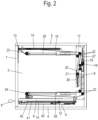
- a piece of furniture 1 comprises a body 2, which has a base 4, two side walls 3, a top 5 and a rear wall 6.
- the body 2 can also have partitions instead of side walls 3 and can be used as a base cabinet or wall cabinet for a kitchen.
- a door 7 is provided on the body 2 as a closing element, which essentially covers an opening on the body 2 in the closed position.
- the door 7 has a handle 8 on the front and can be pivoted upwards about a substantially horizontal axis.
- Figure 2 the furniture 1 is shown in a sectional side view in a closed position in which the door 7 covers an opening on the body 2.
- the furniture 1 with the mechanism is mirror-imaged on opposite side walls 3, so that only the mechanism on one side of the furniture 1 is explained.
- only a single mechanism can be provided.
- a holder 13 is provided on the door 7, on which a guide element 33 is formed with outwardly projecting sliders that can be moved in a vertical guide track 32 or in a horizontal guide track 14.
- the guide track 14, 32 is formed in the shape of a groove in a side wall 3.
- a cable pull 15 is fixed to the holder 13 and can be moved together with the door 7.
- the pull-out guide 10 is also provided with a self-closing mechanism 11, which comprises a stationary housing on which a driver is slidably guided.
- the driver can be pre-tensioned into a retracted position by a spring and optionally also braked in the closing direction by a damping device.
- the driver can be coupled over a certain distance to an activator 12, which is fixed to the guide rail 42 and has a projection that can be brought into engagement with the driver. This pre-tensions the push element 9 into a closed position and prevents it from hitting the door 7, even if the pull-out guide 10 is mounted at a slight angle.
- a guide element 33 is fixed to an upper corner of the door 7, which is guided with a pin or another sliding element in the horizontal guide track 14 and with another sliding element in a vertical guide track 32, wherein the lower slider of the guide element 33 is first moved vertically along the guide track 32 and can then be inserted into the horizontal guide track 14 in order to move the door 7 horizontally.
- the door 7 can thus be pivoted and moved along the guide tracks 32 and 14 by two sliding elements spaced apart from one another.
- the sliding element 9 is shown on the pull-out guide 10, which is also connected to the cable pull 15.
- a connecting element 16 is provided on the guide rail 42, to which the cable pull 15 or a section of the cable pull 15 is fixed.
- FIG 4 the door 7 is shown in a pivoted-up position, in which the door has essentially been pivoted from a vertical closed position into a horizontal first opening position.
- the slider on the guide element 33 has been moved along the vertical guide track 32 up to the level of the guide track 14, so that now both sliders are arranged in the guide track 14 and the door 7 can be moved.
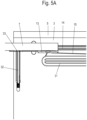
- the cable pull was moved slightly, as can be seen from the comparison of the Figures 3A and 5A shows. This allows the sliding element 9 to be optionally pushed out over a first distance. Alternatively, the sliding element 9 initially remains in the retracted closed position during the pivoting movement of the door 7, and the sliding element 9 is only pushed out when the door 7 is pushed into the body 2.
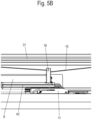
- the cable pull 15 is guided in a substantially U-shape on a side wall of the body 2 and initially runs substantially horizontally from a deflection roller 23, which is rotatably mounted on a web 25, to a plate 17, which is fixed to the side wall 3 in the rear area of the body adjacent to the rear wall 6.
- a plurality of deflection rollers 22 for deflecting the cable pull 15 are provided on the plate 17, as well as two tensioning elements.
- a first tensioning element comprises a slider 18, which is slidably mounted on the plate 17 and is pre-tensioned by a spring 27.
- a second tensioning element comprises a displaceable slider 20, which is pre-tensioned by a spring 28, with a deflection roller 21 being rotatably mounted on the slider 20.
- the deflection rollers 19 and 21, which are rotatably mounted on the slides 18 and 20, ensure that the cable pull 15 is tensioned.
- the tensioning devices provide a certain buffer so that a movement of the door 7 does not directly affect the sliding element 9, but with a time delay via the clamping element with the slide 20 or the clamping device with the slide 18.
- a damping device 29 is provided on the plate 17, which is designed as a linear damper and can brake the slide 18.
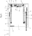
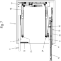
- FIG 7 the door 7 has been moved into the second opening position, in which the door 7 is arranged predominantly on an upper receptacle in the body 2 and only one end section with the handle 8 protrudes from the body 2.
- the push element 9 is currently in the ejection phase and is moved via the pull-out guide 10 into the maximum opening position, which is in Figure 8 is shown.
- the slider 20 is used for this purpose, which is pre-tensioned in the lower position via the spring 28, which is designed as a tension spring, so that the cable pull 15 continues to move after reaching the end position on the door 7 until the push element 9 is also arranged in the maximum opening position, at which the connecting element 16 is located below a deflection roller 24.
- the deflection roller 24 is rotatably mounted on a web 26, which together with the web 25 and the plate 17 forms an assembly unit for the cable pull 15.
- the deflection rollers 23 and 24 can also be mounted directly on the side wall 3.
- the user can place a device on the push element 9, for example a
- Coffee machine or a toaster or other appliances can be used without the door 7 being a hindrance, since these are mostly stored in the body 2.
- the furniture 1 can also be used with the door 7 open without the door 7 hindering the user.
- the sliding element 9 can be retracted into the body 2 by moving the door 7 from the second opening position back to the first opening position, and the door 7 can be brought into a closed position in order to arrange the device or objects in a protected manner on the sliding element 9.
- the door can also be moved from the second opening position back to the first opening position by pushing in the sliding element.
- the connecting element 16 is shown in the maximum opening position, wherein the deflection roller 24 is covered by a cover 31.
- the transmission mechanism is shown in the rear area on the side wall 3.
- the cable pull 15 is guided on the plate 17 over several deflection rollers 22, which are arranged stationary and are only rotatably mounted.
- the upper slider 18 can also be seen, which is tensioned by a spring 27, in particular a tension spring.
- a spring 27 in particular a tension spring.
- a slider 20 is also provided on the other strand of the cable pull 15, which is pre-tensioned by the spring 28 as a tension spring and prevents a movement of the door 7 from being transmitted directly to the push element 9, but only via the storage with the movable deflection roller 21.
- an assembly aid 43, 44 is also inserted into the slides 18, 20 pre-tensioned by the springs 27, 28 as a transport lock. This means that at least one traction device can be laid almost stress-free. Alternatively, the assembly aid 43, 44 can also directly secure the springs 27, 28.
- the door 7 is only connected to one sliding element 9. It is also possible to connect the door 7 to two or more sliding elements that can move over different distances in the opening direction.
- the door 7 is designed as a pivotable flap that can be stowed underneath an upper floor 5 on the body 2. It is also possible to mount the door 7 so that it can rotate about a substantially vertical axis and to be able to slide the door 7 into a receptacle on the side of the body 2. Furthermore, if the width-depth ratio of the furniture is unfavourable, it is also possible to close the opening with a double-leaf door and to insert the individual door leaves into opposite sections of the body 2.
- FIGS 13A and 13B an alternative design of a piece of furniture 1' not according to the invention is shown, in which an opening of a body can be closed by two doors 7', i.e. by a multi-leaf door.
- each door 7' is mounted on a slide 13' via one or more hinges so as to be pivotable about a substantially vertical axis.
- each door 7' can then be pushed into the body 2' on the slide 13' in order to stow the door 7' at least partially in the body 2'.
- a transmission device moves a sliding element 9', in particular a drawer, out of the body 2' in an opening direction.
- the slide 13' can be guided along two spaced-apart guide tracks.
- the transmission device can correspond to the previous embodiment, wherein optionally a synchronization of the movement sequences of the two doors 7' can also be provided so that they are opened or closed together.
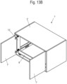
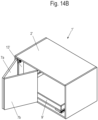
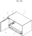
- FIGs 14A to 14D a further embodiment of a piece of furniture 1' not according to the invention is shown, in which an opening of a body 2' can be closed by a door 7', which is designed as a folding door with at least two door elements 7a and 7b held together in an articulated manner.
- the door element 7b facing the middle of the body is displaceable along a guide on a front side of the body 2' in order to be able to move from a closed position ( Fig. 14A ) to be unfolded ( Fig. 14B ) into a first opening position ( Fig. 14C ).
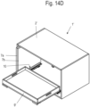
- the folded door 7' can then be pushed into the body 2' using a slide 13' in order to arrange the door 7' at least partially in the body 2'.
- a push element 9' held on pull-out guides 10 is moved out of the body 2' in an opening direction by a transmission device, as has already been described in detail above.
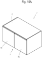
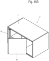
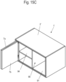
- FIG. 15A to 15D an embodiment of a piece of furniture 1' not according to the invention is shown, in which, according to the embodiment of Figures 14A to 14D, a door 7' is provided as a folding door with two door elements 7a and 7b at the opening of the body 2'.
- a sliding element 90 arranged in the body 2' is designed as an inner body and has a base 91, side walls 92 and a top floor 93.
- a dividing floor 94 can be provided in the inner body for further subdivision.
- the sliding element 90 fills an interior of the body 2' in a retracted position, wherein the sliding element 90 can optionally be adapted to the respective intended use.
Landscapes
- Engineering & Computer Science (AREA)
- Mechanical Engineering (AREA)
- Power-Operated Mechanisms For Wings (AREA)
- Closing And Opening Devices For Wings, And Checks For Wings (AREA)
Description
- Die vorliegende Erfindung betrifft ein Möbel, mit einem Korpus, an dem an einer Öffnung mindestens eine Tür bewegbar gelagert ist, und mindestens ein Schubelement verschiebbar an dem Korpus gelagert ist, wobei die mindestens eine Tür von einer die Öffnung überdeckenden Schließposition über eine Schwenkeinrichtung in eine erste Öffnungsposition verschwenkbar ist, und ein Verfahren zum Öffnen mindestens einer Tür an einem Korpus.
- Die
DE 20 2015 003 223 U1 offenbart ein Möbel mit einem Möbelkorpus, an dem eine schwenkbare Tür und ein verfahrbares Auszugsgestell vorgesehen sind. Durch eine Schwenkbewegung der Tür kann das Auszugsgestell verfahren werden, wobei die Tür in den Raum hineinragt und somit den Nutzer stört. Der Nutzer ist daher bestrebt, das Auszugsgestell nach Benutzung unmittelbar wieder einzuschieben und die Tür zu schließen. - Die
EP 2 055 653 A1 offenbart einen Mechanismus zum Bewegen eines Trägers für einen Abfalleimer, bei dem an einer schwenkbaren Tür ein Hebelmechanismus gekoppelt ist, mittels dem ein Mülleimer von einer eingefahrenen Position in eine ausgefahrene Position herausziehbar ist. Auch hier ist nachteilig, dass die Tür in der geöffneten Position den Nutzer stört und somit nach Gebrauch ein unmittelbares Schließen erforderlich ist. Dieser Mechanismus eignet sich daher nicht zum Bewegen von Schubelementen, auf oder in denen Gebrauchsgegenstände, wie Haushaltsgeräte, beispielsweise Kaffeemaschinen, Toaster oder andere Gegenstände, gelagert sind. - Es sind zudem Möbel aus der
FR 60 685 FR 1 008 995 FR 1 224 059 DE 1 826 773 U offenbart ein Büromöbel mit einem Kaffee-Automaten, der auf eine Zugbrett angeodnet ist. Das Zugbrett kann durch einen Klappdeckel bewegt werden, wenn dieser in das Möbel eingeschoben wird und einen Hebei antreibt, der in eine Öffnung des Zugbrettes eingreift. - Es ist daher Aufgabe der vorliegenden Erfindung, ein Möbel zu schaffen, das eine verbesserte Raumausnutzung ermöglicht, und wobei der Korpus sowohl in einer geschlossenen als auch in einer geöffneten Position genutzt werden kann.
- Diese Aufgabe wird mit einem Möbel mit den Merkmalen des Anspruches 1 sowie einem Verfahren mit den Merkmalen des Anspruches 11 gelöst.
- Bei dem erfindungsgemäßen Möbel ist mindestens eine Tür vorgesehen, die von einer Schließposition in eine erste Öffnungsposition verschwenkbar ist und von dieser ersten Öffnungsposition in eine zweite Öffnungsposition verschiebbar ist, wobei durch eine Übertragungseinrichtung durch das Verschieben der Tür das Schubelement in eine Öffnungsrichtung heraus bewegbar ist. Dadurch ist es möglich, dass wahlweise die Tür nur in die erste Öffnungsposition verschwenkt wird, um Gegenstände in dem Korpus zu bedienen, herauszunehmen oder abzulegen, während alternativ auch die Tür von einer ersten Öffnungsposition in eine zweite Öffnungsposition verschoben werden kann, um dann das Schubelement in Öffnungsrichtung auszuschieben. Dadurch kann die Tür in eine zumindest teilweise verstaute Position bewegt werden, und das das Haushaltsgerät kann mit zumindest teilweise, vorzugsweise vollständig ausgefahrenem Schubelement bedient werden. Dies ermöglicht eine flexiblere Nutzung des Möbels, wobei an dem Schubelement eine Kaffeemaschine oder ein Toaster vorgesehen ist, das dann bei ausgeschobenem Schubelement einfach bedienbar ist. Bei besonders breiten Möbeln kann die Tür auch mehrflügelig gestaltet sein und die jeweils einzelnen Türflügel an gegenüberliegenden Seiten der Öffnung gelagert und in den daran benachbarten Abschnitten verstaut werden. Dazu wird beidseitig eine Übertragungseinrichtung verbaut, die ihrerseits über Synchronisationsmittel verfügen kann, um den Ablauf der mehrflügeligen Tür gleichförmig zu steuern. Auch bei der einflügeligen Tür ist für einen gleichförmigen Ablauf auch die Verwendung von jeweils einer Übertragungsvorrichtung pro Schubelementseite denkbar.
- Erfindungsgemäß umfasst die Übertragungseinrichtung mindestens ein Zugmittel, beispielsweise einen Seilzug, der mit der Tür und dem mindestens einen Schubelement verbunden ist. Der Seilzug kann dabei umlaufend ausgebildet sein, um Zugkräfte in gegenüberliegende Bewegungsrichtungen ausüben zu können. Es ist auch möglich, einen Seilzug aus mehreren einzelnen Seilzugabschnitten zu bilden, der dann für eine entsprechende Kopplung des mindestens einen Schubelementes mit der Tür sorgt. In einer alternativen Ausgestaltung kann das Übertragungselement auch ein anderes biegbares Zugmittel, beispielsweise einen Riemen oder Kettentrieb zur kraft- und/ oder formschlüssigen Übertragung umfassen.
- In einer weiteren Ausgestaltung ist die Tür von einer ersten Öffnungsposition in die zweite Öffnungsposition im Wesentlichen in horizontale Richtung verschiebbar. Dadurch lässt sich die Tür vergleichsweise leichtgängig verschieben, wobei die Tür vorzugsweise in den Korpus eingeschoben wird, beispielsweise in eine Aufnahme an dem Korpus. Ein Teil der Tür, beispielsweise ein Abschnitt mit einem Griffelement, kann von dem Korpus in der zweiten Öffnungsposition noch hervorstehen. Dadurch ist die Tür allerdings überwiegend im Korpus verstaut.
- Das Schubelement ist erfindungsgemäß an zwei Auszugsführungen verschiebbar gehalten. Das Schubelement ist als Tablar ausgebildet, auf dem Haushaltsgeräte oder andere Gegenstände abgestellt oder aufgenommen sind.
- Die Schwenkeinrichtung ist vorzugsweise verschiebbar an dem Korpus gelagert. Die Schwenkeinrichtung kann dabei eines oder mehrere Scharniere umfassen, die die Tür um eine vertikale Schwenkachse verschwenkt, oder alternativ kann die Tür um eine horizontale Schwenkachse verschwenkbar sein. Die Schwenkachse muss dabei nicht stationär sein, sondern kann entlang einer Bewegungsbahn geführt sein, so dass auch Vier-Gelenk oder Sieben-GelenkScharniere oder Klappenbeschläge eingesetzt werden können. In einer einfachen Ausgestaltung umfasst die Schwenkeinrichtung lediglich Zapfen, die in einer linearen Führung verschiebbar gelagert sind, so dass die Tür um die an gegenüberliegenden Seiten hervorstehenden Zapfen sowohl gedreht als auch verschoben werden kann. Dabei können an jeder Seite der Tür zwei voneinander beabstandete Zapfen vorgesehen sein, die entlang von zwei winklig angeordneten Führungsbahnen bewegbar sind, so dass in einem ersten Schritt die Tür verschwenkt wird, und wenn beide Zapfen in der gleichen Führungsbahn angeordnet sind, kann die Tür linear verschoben werden. Alternativ ist die Tür an Scharnieren oder Klappenbeschlägen gehalten, die an einem Schlitten verschiebbar geführt sind.
- Vorzugsweise ist mittels der Übertragungseinrichtung das mindestens eine Schubelement beim Verschwenken der Tür zumindest über eine erste Wegstrecke ausschiebbar. Dadurch wird die Bewegung der Tür schon genutzt, um das Schubelement zumindest über einen kleineren Teil der Wegstrecke in Öffnungsrichtung auszuschieben, wobei dann beim Verschieben der Tür von der ersten Öffnungsposition in die zweite Öffnungsposition das Schubelement über einen größeren Teil der Wegstrecke in Öffnungsrichtung ausgeschoben wird. Das Schubelement ist dabei horizontal verfahrbar, so dass es in der ausgeschobenen Position verbleiben kann, wobei optional Rast- oder Verriegelungseinrichtungen vorgesehen sind, um das Schubelement gegen ein Verschieben aus der ausgeschobenen Öffnungsposition zu sichern.
- In einer weiteren Ausgestaltung ist mindestens eine Feder vorgesehen, um den Seilzug der Übertragungseinrichtung vorzuspannen. Dies erhöht den Komfort beim Betätigen der Tür und/oder des Schubelementes. Zudem kann optional eine Dämpfungsvorrichtung vorgesehen sein, um die Tür bei der Schließbewegung aus der ersten Öffnungsposition in die Schließposition abzubremsen, was harte Anschlagsgeräusche vermeidet.
- Vorzugsweise ist an der Öffnung des Korpus eine ein- oder zweiflügelige Tür bewegbar gelagert. Optional kann die Tür auch als Falttür mit mindestens zwei gelenkig aneinander gehaltenen Türelementen ausgebildet sein ist, so dass die Tiefe des Korpus geringer ausgebildet sein kann als die Breite der aus zwei Türelementen gebildeten Tür.
- Bei dem erfindungsgemäßen Verfahren nach Anspruch 11 wird eine Tür zunächst von einer Schließposition in eine Öffnungsposition verschwenkt, um dann die Tür von der Öffnungsposition in eine zweiten Öffnungsposition zu verschieben, vorzugsweise in horizontale Richtung, um dadurch über eine Übertragungseinrichtung ein Schubelement zumindest teilweise in Öffnungsrichtung auszuschieben. Über die Übertragungseinrichtung kann das Schubelement auch vollständig von der Schließposition in eine Öffnungsposition bewegt werden. Erst beim Verschieben der Tür von der zweiten Öffnungsposition zurück in die erste Öffnungsposition kann dann das Schubelement wieder in Schließrichtung über die Übertragungseinrichtung verfahren werden. Dadurch wird die Handhabung vereinfacht. Alternativ kann aber auch durch Einschieben des Schubelements die Tür aus der zweiten Öffnungsposition zurück in die erste Öffnungsposition bewegt werden, wobei sie dort aus Sicherheitsgründen verharrt und nicht direkt in die geschlossene Position weiterbewegen kann bzw. bei horizontalen Schwenkachsen in eine geschlossene Position fallen kann.
- Die Erfindung wird nachfolgend anhand eines Ausführungsbeispiels mit Bezug auf die beigefügten Zeichnungen näher erläutert. Es zeigen:
-
Figur 1 eine perspektivische Ansicht eines erfindungsgemäßen Möbels, wobei die Kaffeemaschine oder der Toaster nicht dargestellt sind, -
Figur 2 eine geschnittene Seitenansicht derFigur 1 in der Schließposition; -
Figuren 3A bis 3C mehrere Detailansichten derFigur 2 in der Schließposition; -
Figur 4 eine geschnittene Seitenansicht derFigur 1 mit hochgeschwenkter Tür; -
Figuren 5A und5B zwei Detailansichten derFigur 4 ; -
Figur 6 eine geschnittene Seitenansicht derFigur 1 beim Einschieben der Tür von der ersten Öffnungsposition in die zweite Öffnungsposition; -
Figur 7 eine geschnittene Seitenansicht derFigur 1 mit der Tür in der zweiten Öffnungsposition; -
Figur 8 eine geschnittene Seitenansicht derFigur 1 mit der Tür in der zweiten Öffnungsposition und dem Schubelement in der maximalen Öffnungsposition; -
Figur 9 eine Detailansicht derFigur 8 ; -
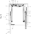
Figur 10 eine geschnittene Seitenansicht derFigur 1 beim Einschieben des Schubelementes; -
Figur 11 eine perspektivische Ansicht der Übertragungseinrichtung in der montierten Position; -
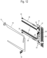
Figur 12 eine perspektivische Explosionsdarstellung der Übertragungseinrichtung des Möbels derFigur 1 ; -
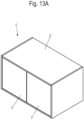
Figur 13A und13B perspektivische Ansichten eines modifizierten nicht erfindungsgemäßen Möbels mit mehrflügliger Bauweise, wobei die Kaffeemaschine oder der Toaster nicht dargestellt sind, -
Figur 14A bis 14D perspektivische Ansichten eines modifizierten nicht erfindungsgemäßen Möbels in unterschiedlichen Positionen, wobei die Kaffeemaschine oder der Toaster nicht dargestellt sind, und -
Figur 15A bis 15D perspektivische Ansichten eines modifizierten nicht erfindungsgemäßen Möbels in unterschiedlichen Positionen, wobei die Kaffeemaschine oder der Toaster nicht dargestellt sind. - Ein Möbel 1 umfasst einen Korpus 2, der einen Boden 4, zwei Seitenwände 3, einen Oberboden 5 und eine Rückwand 6 aufweist. Der Korpus 2 kann statt Seitenwänden 3 auch Zwischenwände aufweisen und als Unterschrank oder Oberschrank für eine Küche eingesetzt werden. An dem Korpus 2 ist eine Tür 7 als Verschlusselement vorgesehen, das eine Öffnung an dem Korpus 2 in der Schließposition im Wesentlichen überdeckt. Die Tür 7 weist an der Vorderseite einen Griff 8 auf und kann um eine im Wesentlichen horizontale Achse nach oben verschwenkt werden. Alternativ ist es möglich, die Tür 7 um eine vertikale Achse seitlich zu verschwenken, wobei die entsprechenden Schwenkachsen nicht stationär ausgebildet sein müssen, sondern auch entlang einer Bahn beim Öffnen oder Schließen bewegt werden können.
- In
Figur 2 ist das Möbel 1 in einer geschnittenen Seitenansicht in einer Schließposition dargestellt, in der die Tür 7 eine Öffnung an dem Korpus 2 überdeckt. Das Möbel 1 mit dem Mechanismus ist an gegenüberliegenden Seitenwänden 3 spiegelbildlich ausgebildet, so dass nur der Mechanismus auf einer Seite des Möbels 1 erläutert wird. Optional kann auch nur ein einziger Mechanismus vorgesehen sein. - An der Tür 7 ist ein Halter 13 vorgesehen, an dem ein Führungselement 33 mit nach außen hervorstehenden Gleitern ausgebildet ist, die in einer vertikalen Führungsbahn 32 oder in einer horizontalen Führungsbahn 14 verfahrbar sind. Die Führungsbahn 14, 32 ist dabei in einer Seitenwand 3 nutförmig ausgebildet. An dem Halter 13 ist ein Seilzug 15 fixiert, der zusammen mit der Tür 7 bewegbar ist.
- Der Seilzug 15 verbindet die Tür 7 mit einem Schubelement 9, das in der Schließposition innerhalb des Korpus 2 angeordnet ist. Das Schubelement 9 ist über eine Auszugsführung 10 verfahrbar gelagert, die zwei oder mehr relativ zueinander bewegbare Schienen aufweisen kann. In dem dargestellten Ausführungsbeispiel besitzt die Auszugsführung 10 eine am Korpus 2 fixierte Führungsschiene 40, eine Mittelschiene 41 sowie eine verfahrbare Laufschiene 42, an der das Schubelement 9 gehalten ist.
- An der Auszugsführung 10 ist ferner ein Selbsteinzug 11 vorgesehen, der ein stationäres Gehäuse umfasst, an dem ein Mitnehmer verschiebbar geführt ist. Der Mitnehmer kann durch eine Feder in eine Einzugsposition vorgespannt sein und optional auch über eine Dämpfungsvorrichtung in Schließrichtung abgebremst werden. Der Mitnehmer ist über eine gewisse Wegstrecke mit einem Aktivator 12 koppelbar, der an der Laufschiene 42 festgelegt ist und einen Vorsprung aufweist, der in Eingriff mit dem Mitnehmer bringbar ist. Dadurch wird das Schubelement 9 in eine Schließposition vorgespannt, und es wird ein Anschlagen an der Tür 7 vermieden, auch wenn die Auszugsführung 10 leicht geneigt montiert sein sollte.
- In den
Figuren 3A und3B ist die Schwenkeinrichtung für die Tür 7 dargestellt. An einer oberen Ecke der Tür 7 ist ein Führungselement 33 festgelegt, dass mit einem Zapfen oder einem anderen Gleitelement in der horizontalen Führungsbahn 14 und mit einem weiteren Gleitelement in einer vertikalen Führungsbahn 32 geführt ist, wobei der untere Gleiter des Führungselementes 33 zunächst entlang der Führungsbahn 32 vertikal verfahren wird und dann in die horizontale Führungsbahn 14 eingefügt werden kann, um die Tür 7 horizontal zu verschieben. Die Tür 7 ist dadurch durch zwei voneinander beabstandete Gleitelemente entlang der Führungsbahnen 32 und 14 verschwenkbar und verschiebbar. Es ist allerdings auch möglich, statt zweier Gleitelemente auch einen Schlitten vorzusehen, an dem Scharniere oder Klappenbeschläge festgelegt sind, um ein Verschwenken der Tür 7 zu führen. - In
Figur 3C ist das Schubelement 9 an der Auszugsführung 10 gezeigt, das ebenfalls mit dem Seilzug 15 verbunden ist. Hierfür ist an der Laufschiene 42 ein Verbindungselement 16 vorgesehen, an dem der Seilzug 15 oder ein Abschnitt des Seilzuges 15 fixiert ist. - In
Figur 4 ist die Tür 7 in einer hochgeschwenkten Position gezeigt, in der die Tür im Wesentlichen von einer vertikalen Schließposition in eine horizontale erste Öffnungsposition verschwenkt wurde. Der Gleiter an dem Führungselement 33 ist entlang der vertikalen Führungsbahn 32 bis nach oben auf Höhe der Führungsbahn 14 verschoben worden, so dass nun beide Gleiter in der Führungsbahn 14 angeordnet sind und die Tür 7 verschoben werden kann. Durch das Verschwenken der Tür wurde der Seilzug geringfügig bewegt, wie dies der Vergleich derFiguren 3A und5A zeigt. Dadurch kann optional das Schubelement 9 über eine erste Wegstrecke ausgeschoben werden. Alternativ bleibt das Schubelement 9 während der Schwenkbewegung der Tür 7 zunächst in der eingefahrenen Schließstellung, und erst beim Einschieben der Tür 7 in den Korpus 2 wird das Schubelement 9 ausgeschoben. - In
Figur 6 wird die Tür 7 in den Korpus 2 eingeschoben, wobei die beiden Gleitelemente entlang der horizontalen Führungsbahn 14 bewegt werden. Dadurch verfährt der Seilzug 15 und zieht das Schubelement 9 über das Verbindungselement 16 in eine Öffnungsposition. Wie inFigur 5B gezeigt ist, ist der Seilzug 15 an gegenüberliegenden Seiten mit dem Verbindungselement 16 verbunden, und durch das Verfahren der Auszugsführung 10 verlässt der Aktivator den Selbsteinzug 11. - Der Seilzug 15 ist im Wesentlichen U-förmig an einer Seitenwand des Korpus 2 geführt und verläuft zunächst im Wesentlichen horizontal von einer Umlenkrolle 23, die an einem Steg 25 drehbar gelagert ist, zu einer Platte 17, die im rückseitigen Bereich des Korpus benachbart zu der Rückwand 6 an der Seitenwand 3 fixiert ist. An der Platte 17 sind eine Vielzahl von Umlenkrollen 22 zur Umlenkung des Seilzuges 15 vorgesehen, und zudem zwei Spannelemente. Ein erstes Spannelement umfasst einen Schieber 18, der verschiebbar an der Platte 17 gelagert ist und über eine Feder 27 vorgespannt ist. Ein zweites Spannelement umfasst einen verschiebbaren Schieber 20, der über eine Feder 28 vorgespannt ist, wobei an dem Schieber 20 eine Umlenkrolle 21 drehbar gelagert ist. Die an den Schieber 18 und 20 drehbar gelagerten Umlenkrollen 19 und 21 sorgen dabei für ein Spannen des Seilzuges 15. Zudem bewirken die Spanneinrichtungen einen gewissen Puffer, so dass eine Bewegung der Tür 7 nicht unmittelbar auf das Schubelement 9 übertragen wird, sondern zeitversetzt über das Spannelement mit dem Schieber 20 oder die Spanneinrichtung mit dem Schieber 18. An der Platte 17 ist ferner eine Dämpfungsvorrichtung 29 vorgesehen, die als Lineardämpfer ausgebildet ist und den Schieber 18 abbremsen kann.
- In
Figur 7 ist die Tür 7 in die zweite Öffnungsposition verfahren worden, in der die Tür 7 überwiegend an einer oberen Aufnahme in dem Korpus 2 angeordnet ist und nur ein Endabschnitt mit dem Griff 8 von dem Korpus 2 hervorsteht. Das Schubelement 9 befindet sich gerade in der Auswurfphase und wird über die Auszugsführung 10 noch in die maximale Öffnungsposition verfahren, die inFigur 8 gezeigt ist. Hierzu dient der Schieber 20, der über die Feder 28, die als Zugfeder ausgebildet ist, in der unteren Stellung vorgespannt ist, so dass der Seilzug 15 sich nach Erreichen der Endstellung an der Tür 7 noch weiter bewegt, bis auch das Schubelement 9 in der maximalen Öffnungsposition angeordnet ist, an der sich das Verbindungselement 16 unterhalb einer Umlenkrolle 24 befindet. Die Umlenkrolle 24 ist dabei an einem Steg 26 drehbar gelagert, der zusammen mit dem Steg 25 und der Platte 17 eine Montageeinheit für den Seilzug 15 ausbildet. Optional können die Umlenkrollen 23 und 24 auch unmittelbar an der Seitenwand 3 gelagert werden. - In der in
Figur 8 dargestellten Öffnungsposition des Schubelementes 9 kann der Benutzer ein Gerät auf dem Schubelement 9, beispielsweise eine - Kaffeemaschine oder einen Toaster oder andere Geräte, nutzen, ohne dass die Tür 7 hinderlich ist, da diese überwiegend in dem Korpus 2 verstaut ist. Insofern lässt sich das Möbel 1 auch mit geöffneter Tür 7 nutzen, ohne dass die Tür 7 den Nutzer behindert.
- Sobald die Nutzung beendet ist, kann durch Verschieben der Tür 7 von der zweiten Öffnungsposition zurück in die erste Öffnungsposition das Schubelement 9 wieder in den Korpus 2 eingezogen werden, und die Tür 7 in eine Schließposition gebracht werden, um das Gerät oder die Gegenstände auf dem Schubelement 9 geschützt anzuordnen. Alternativ kann aber auch durch Einschieben des Schubelements die Tür aus der zweiten Öffnungsposition zurück in die erste Öffnungsposition bewegt werden.
InFigur 9 ist das Verbindungselement 16 in der maximalen Öffnungsposition gezeigt, wobei die Umlenkrolle 24 durch eine Abdeckung 31 überdeckt ist. - In
Figur 10 wurde das Schubelement 9 in Schließrichtung bewegt, wobei das Verbindungselement 16 sich über eine größere Wegstrecke von der Umlenkrolle 24 entfernt hat als die Tür 7 von der zweiten Öffnungsposition. Dies liegt daran, dass ein Teil des Seilzuges 15 durch Verfahren des Schiebers 18 im Bereich der Platte 17 gespeichert wurde, da die Umlenkrolle 19 sich von der Dämpfungsvorrichtung 29 entfernt hat. Der Nutzer kann nun die Tür 7 an dem Griff 8 bewegen und in die erste Öffnungsposition verschieben, die inFigur 4 gezeigt ist. Von dieser Position kann die Tür 7 wieder in die Schließposition verschwenkt werden, wobei durch Bewegen der Tür 7 das Schubelement 9 automatisch in die Schließposition verfahren wird. - In
Figur 11 ist der Übertragungsmechanismus im rückwärtigen Bereich an der Seitenwand 3 dargestellt. Der Seilzug 15 wird an der Platte 17 über mehrere Umlenkrollen 22 geführt, die stationär angeordnet sind und nur drehbar gelagert sind. Ferner ist der obere Schieber 18 erkennbar, der durch eine Feder 27, insbesondere eine Zugfeder, gespannt ist. Bei einem Ziehen am dem Schubelement 9 wird der Schieber 18 gegen die Kraft der Feder 27 verfahren, und durch die Dämpfungsvorrichtung 29 wird verhindert, dass der Schieber 18 ungebremst an einem Anschlag auftrifft, beispielsweise wenn die Tür 7 noch nicht weit genug in den Korpus 2 eingeschoben ist. Auch an dem anderen Strang des Seilzuges 15 ist ein Schieber 20 vorgesehen, der durch die Feder 28 als Zugfeder vorgespannt ist und verhindert, dass eine Bewegung der Tür 7 unmittelbar auf das Schubelement 9 übertragen wird, sondern nur über den Speicher mit der bewegbaren Umlenkrolle 21. - Für den Transport sind ferner an den durch die Federn 27, 28 vorgespannten Schiebern 18, 20 jeweils eine Montagehilfe 43, 44 als Transportsicherung eingesteckt. Somit kann das mindestens eine Zugmittel nahezu spannungsfrei verlegt werden. Alternativ kann die Montagehilfe 43, 44 auch direkt die Federn 27, 28 sichern-
- In
Figur 12 ist der Übertragungsmechanismus zwischen der Tür 7 und dem Schubelement 9 im Detail dargestellt. An einem oberen Steg 25 befindet sich eine stationäre Umlenkrolle 23 für den Seilzug, und an einem unteren Steg 26 befindet sich eine weitere stationäre Umlenkrolle 24. Im rückwärtigen Bereich ist die Platte 17 mit zahlreichen Umlenkrollen 22 vorgesehen, an dem auch die beiden Schieber 18 und 20 mit jeweils einer verschiebbaren Umlenkrolle 19 und 21 vorgesehen sind, wobei die Schieber über Federn 27 und 28 vorgespannt sind. Dadurch wird der Seilzug 15 ständig auf Spannung gehalten. Der Übertragungsmechanismus ist zum Innenraum des Korpus 2 über leistenförmige Abdeckungen 31 und die Platte 17 über eine Abdeckung 30 verdeckt. Der Seilzug 15 ist dabei im Wesentlichen U-förmig geführt, um die Tür 7 mit dem Schubelement 9 zu verbinden. - In dem dargestellten Ausführungsbeispiel ist die Tür 7 nur mit einem Schubelement 9 verbunden. Es ist auch möglich, die Tür 7 mit zwei oder mehr Schubelementen zu verbinden, die sich über eine unterschiedliche Wegstrecke in Öffnungsrichtung bewegen können.
- In dem dargestellten Ausführungsbeispiel ist die Tür 7 als verschwenkbare Klappe ausgebildet, die unterhalb eines Oberbodens 5 an dem Korpus 2 verstaut werden kann. Es ist auch möglich, die Tür 7 um eine im Wesentlichen vertikale Achse drehbar zu lagern und die Tür 7 seitlich an dem Korpus 2 in einer Aufnahme einschieben zu können. Desweiteren ist es auch möglich bei ungünstigen Breiten-Tiefen-Verhältnis des Möbels die Öffnung durch eine doppelflügelige Tür zu verschließen und die einzelnen Türflügel in gegenüberliegende Abschnitte des Korpus 2 einzuschieben.
- In
Figuren 13A und13B ist eine alternative Bauweise eines nicht erfindungsgemäßen Möbels 1' gezeigt, bei dem eine Öffnung eines Korpus durch zwei Türen 7' verschlossen werden kann, also durch eine mehrflügelige Tür. Hierfür ist jede Tür 7' an einem Schlitten 13' über ein oder mehrere Scharniere um eine im Wesentlichen vertikale Achse verschwenkbar gelagert. Nach einer - Öffnungsbewegung in die in
Figur 13B gezeigte Stellung kann dann jede Tür 7' an dem Schlitten 13' in den Korpus 2' eingeschoben werden, um die Tür 7' zumindest teilweise in dem Korpus 2' zu verstauen. Durch das Einschieben der Tür 7' von der ersten Öffnungsposition in eine zweite eingeschobene Öffnungsposition wird durch eine Übertragungseinrichtung ein Schubelement 9', insbesondere ein Schubkasten, in eine Öffnungsrichtung aus dem Korpus 2' herausbewegt. Der Schlitten 13' kann dabei entlang von zwei beabstandeten Führungsbahnen geführt sein. Die Übertragungseinrichtung kann dem vorangegangen Ausführungsbeispiel entsprechen, wobei optional auch eine Synchronisierung der Bewegungsabläufe der beiden Türen 7' vorgesehen sein kann, so dass diese gemeinsam geöffnet oder geschlossen werden. - In
Figuren 14A bis 14D ist eine weitere Ausführungsform eines nicht erfindungsgemäßen Möbels 1'gezeigt, bei dem eine Öffnung eines Korpus 2' durch eine Tür 7' verschlossen werden kann, die zwei als Falttür mit mindestens zwei gelenkig aneinander gehaltenen Türelementen 7a und 7b ausgebildet ist. Das zur Korpusmitte gewandte Türelement 7b ist dabei entlang einer Führung an einer Vorderseite des Korpus 2' verschiebbar, um von einer geschlossenen Position (Fig. 14A ) aufgefaltet zu werden (Fig. 14B ) in eine erste Öffnungsposition (Fig. 14C ). Aus der ersten Öffnungsposition ist dann die zusammengefaltete Tür 7' mit einem Schlitten 13' in den Korpus 2' einschiebbar, um die Tür 7' zumindest teilweise in dem Korpus 2' anzuordnen. Wie bei den vorangegangenen Ausführungsbeispielen wird durch das Einschieben der Tür 7' von der ersten Öffnungsposition in eine zweite eingeschobene Öffnungsposition durch eine Übertragungseinrichtung ein an Auszugsführungen 10 gehaltenes Schubelement 9' in eine Öffnungsrichtung aus dem Korpus 2' herausbewegt, wie dies vorstehend schon im Detail beschrieben wurde. - In den
Figuren 15A bis 15D ist eine Ausführungsform eines nicht erfindungsgemäßen Möbels 1' gezeigt, bei dem entsprechend dem Ausführungsbeispiel der Figuren 14A bis 14D eine Tür 7' als Falttür mit zwei Türelementen 7a und 7b an der Öffnung des Korpus 2' vorgesehen ist. Ein in dem Korpus 2' angeordnetes Schubelement 90 ist als Innenkorpus ausgebildet und weist einen Boden 91, Seitenwände 92 und einen Oberboden 93 auf. Optional kann in dem Innenkorpus ein Trennboden 94 zur weiteren Unterteilung vorgesehen sein. Das Schubelement 90 füllt einen Innenraum des Korpus 2' in einer eingefahrenen Position aus, wobei das Schubelement 90 optional an den jeweiligen Gebrauchszweck angepasst werden kann. -
- 1,1'
- Möbel
- 2,2'
- Korpus
- 3
- Seitenwand
- 4
- Boden
- 5
- Oberboden
- 6
- Rückwand
- 7,7'
- Tür
- 8
- Griff
- 9,9'
- Schubelement
- 10
- Auszugsführung
- 11
- Selbsteinzug
- 12
- Aktivator
- 13
- Halter
- 13'
- Schlitten
- 14
- Führungsbahn
- 15
- Zugmittel/ Seilzug
- 16
- Verbindungselement
- 17
- Platte
- 18
- Schieber
- 19
- Umlenkrolle
- 20
- Schieber
- 21-24
- Umlenkrolle
- 25
- Steg
- 26
- Steg
- 27
- Feder
- 28
- Feder
- 29
- Dämpfungsvorrichtung
- 30
- Abdeckung
- 31
- Abdeckung
- 32
- Führungsbahn
- 33
- Führungselement
- 40
- Führungsschiene
- 41
- Mittelschiene
- 42
- Laufschiene
- 43
- Montagehilfe
- 44
- Montagehilfe
Claims (13)
- Möbel (1, 1') mit einem Korpus (2, 2'), an dem an einer Öffnung mindestens eine Tür (7, 7') bewegbar gelagert ist, und mindestens ein Schubelement (9) verschiebbar an dem Korpus (2, 2') gelagert ist, wobei die mindestens eine Tür (7, 7') von einer die Öffnung zumindest teilweiseüberdeckenden Schließposition über eine Schwenkeinrichtung in eine erste Öffnungsposition verschwenkbar ist, wobei die mindestens eine Tür (7, 7') von der ersten Öffnungsposition in eine zweite Öffnungsposition verschiebbar ist und durch mindestens eine Übertragungseinrichtung (15) durch das Verschieben der Tür (7, 7') das Schubelement (9, 9', 90) in eine Öffnungsrichtung heraus bewegbar ist, dadurch gekennzeichnet, dass an dem Schubelement (9, 9', 90) eine Kaffeemaschine oder ein Toaster vorgesehen ist, wobei das mindestens eine Schubelement (9, 9', 90) an zwei Auszugsführungen (10) verschiebbar gehalten ist und als Tablar ausgebildet ist, wobei die Übertragungseinrichtung (15) mindestens ein Zugmittel, insbesondere einen Seilzug, einen Riementrieb oder Kettentrieb umfasst, das mit der mindestens einen Tür (7, 7') und dem mindestens einen Schubelement (9, 9', 90) verbunden ist.
- Möbel nach Anspruch 1, dadurch gekennzeichnet, dass die mindestens eine Tür (7, 7') von der ersten Öffnungsposition in die zweite Öffnungsposition im Wesentlichen in horizontale Richtung verschiebbar ist, und die mindestens eine Tür (7, 7') in der zweiten Öffnungsposition überwiegend in einer Aufnahme in dem Korpus (2, 2') eingefügt ist.
- Möbel nach Anspruch 1 oder 2, dadurch gekennzeichnet, dass die Schwenkeinrichtung verschiebbar an dem Korpus (2, 2') gelagert ist.
- Möbel nach einem der vorhergehenden Ansprüche, dadurch gekennzeichnet, dass die Schwenkeinrichtung mindestens ein Scharnier umfasst und die Tür (7') um eine vertikale Schwenkachse verschwenkbar ist oder mindestens einen Klappenbeschlag umfasst und um eine horizontale Schwenkachse verschwenkbar ist.
- Möbel nach einem der vorhergehenden Ansprüche, dadurch gekennzeichnet, dass mittels der Übertragungseinrichtung (15) beim Verschieben der mindestens einen Tür (7, 7') in die zweite Öffnungsposition das mindestens eine Schubelement (9, 9') über mindestens einen Teil der Wegstrecke heraus bewegbar ist.
- Möbel nach einem der vorhergehenden Ansprüche, dadurch gekennzeichnet, dass mindestens eine Feder (27, 28) vorgesehen ist, um das Zugmittel, insbesondere den Seilzug, Riementrieb oder Kettentrieb der Übertragungseinrichtung (15) gespannt zu halten.
- Möbel nach einem der vorhergehenden Ansprüche, dadurch gekennzeichnet, dass eine Dämpfungsvorrichtung (29) vorgesehen ist, um die Tür (7, 7') bei der Schließbewegung aus der ersten Öffnungsposition in die Schließposition abzubremsen.
- Möbel nach einem der vorhergehenden Ansprüche, dadurch gekennzeichnet, dass an der Öffnung der Korpus (2') eine zweiflügelige Tür (7') bewegbar gelagert ist.
- Möbel nach Anspruch 8, dadurch gekennzeichnet, dass Synchronisierungsmittel die Übertragungsvorrichtungen der zweiflügeligen Tür (7') miteinander koppelt.
- Möbel nach einem der vorhergehenden Ansprüche, dadurch gekennzeichnet, dass an der Öffnung der Korpus (2') eine Tür (7') als Falttür mit mindestens zwei gelenkig aneinander gehaltenen Türelementen (7a, 7b) vorgesehen ist.
- Verfahren zum Öffnen mindestens einer Tür (7, 7') an einem Korpus (2, 2') eines Möbels (1, 1'), mit den folgenden Schritten: Verschwenken mindestens einer Tür (7, 7') von einer Schließposition in eine erste Öffnungsposition, gekennzeichnet durch ein Verschieben der mindestens einen Tür von der ersten Öffnungsposition in eine zweite Öffnungsposition, wobei über mindestens eine Übertragungseinrichtung mit mindestens einem Zugmittel, insbesondere einem Seilzug, einem Riementrieb oder Kettentrieb umfasst, das mit der mindestens einen Tür (7, 7') und dem mindestens einen Schubelement (9, 9', 90) verbunden ist, dadurch mindestens ein an zwei Auszugsführungen (10) verschiebbar gehaltenes Schubelement (9), das als Tablar ausgebildet ist, zumindest teilweise in Öffnungsrichtung ausgeschoben wird, wobei an dem Schubelement (9, 9', 90) eine Kaffeemaschine oder ein Toaster vorgesehen ist.
- Verfahren nach Anspruch 11, dadurch gekennzeichnet, dass beim Verschieben der mindestens einen Tür (7, 7') von der zweiten Öffnungsposition in die erste Öffnungsposition das mindestens eine Schubelement (9, 9', 90) in Schließrichtung verfahren wird.
- Verfahren nach Anspruch 11 oder 12, dadurch gekennzeichnet, dass beim Verschieben des mindestens einen Schubelements (9) in Schließrichtung die mindestens eine Tür (7, 7') von der zweiten Öffnungsposition in die erste Öffnungsposition verfahren wird.
Applications Claiming Priority (2)
| Application Number | Priority Date | Filing Date | Title |
|---|---|---|---|
| DE102017116061.2A DE102017116061A1 (de) | 2017-07-17 | 2017-07-17 | Möbel oder Haushaltsgerät und Verfahren zum Öffnen einer Tür |
| PCT/EP2018/068017 WO2019015956A1 (de) | 2017-07-17 | 2018-07-04 | Möbel oder haushaltsgerät und verfahren zum öffnen einer tür |
Publications (3)
| Publication Number | Publication Date |
|---|---|
| EP3654803A1 EP3654803A1 (de) | 2020-05-27 |
| EP3654803B1 EP3654803B1 (de) | 2021-12-08 |
| EP3654803B2 true EP3654803B2 (de) | 2025-01-01 |
Family
ID=62816571
Family Applications (1)
| Application Number | Title | Priority Date | Filing Date |
|---|---|---|---|
| EP18737250.3A Active EP3654803B2 (de) | 2017-07-17 | 2018-07-04 | Möbel mit einer kaffemaschine oder einem toaster und verfahren zum öffnen einer tür |
Country Status (3)
| Country | Link |
|---|---|
| EP (1) | EP3654803B2 (de) |
| DE (1) | DE102017116061A1 (de) |
| WO (1) | WO2019015956A1 (de) |
Families Citing this family (11)
| Publication number | Priority date | Publication date | Assignee | Title |
|---|---|---|---|---|
| AT521149B1 (de) * | 2018-11-13 | 2019-11-15 | Blum Gmbh Julius | Anordnung zur Führung eines bewegbaren Möbelteils |
| AT523872B1 (de) * | 2020-06-05 | 2023-07-15 | Blum Gmbh Julius | Führungssystem |
| AT524635B1 (de) * | 2020-12-17 | 2022-10-15 | Blum Gmbh Julius | Anordnung zur Führung wenigstens eines bewegbaren Möbelteiles relativ zu einem Möbelkorpus |
| US12130004B2 (en) | 2021-07-13 | 2024-10-29 | Kohler Co. | Mirror and cabinet apparatus |
| USD1064653S1 (en) | 2022-07-06 | 2025-03-04 | Kohler Co. | Cabinet |
| DE102022132280B3 (de) * | 2022-12-06 | 2024-03-21 | Miele & Cie. Kg | System mit einem Haushaltgerät und einem Möbel zur Aufnahme des Haushaltgeräts sowie Verfahren zum Betrieb eines Systems |
| BE1031411B1 (de) * | 2023-03-08 | 2024-10-08 | Miele & Cie | System mit einem Haushaltsgerät sowie Verfahren zum Betrieb eines Systems |
| EP4427632A1 (de) | 2023-03-07 | 2024-09-11 | Miele & Cie. KG | System mit einem haushaltsgerät sowie verfahren zum betrieb eines systems |
| DE102024102467A1 (de) * | 2024-01-29 | 2025-07-31 | Miele & Cie. Kg | Haushaltgerät und Verfahren zum Betreiben |
| DE102024123040A1 (de) | 2024-08-13 | 2026-02-19 | Miele & Cie. Kg | Getränkezubereitungsgerät und Verfahren zum Betreiben eines Getränkezubereitungsgeräts |
| DE102024123034A1 (de) | 2024-08-13 | 2026-02-19 | Miele & Cie. Kg | Getränkeautomat und Verfahren zum Betreiben eines Getränkeautomaten |
Family Cites Families (11)
| Publication number | Priority date | Publication date | Assignee | Title |
|---|---|---|---|---|
| US2405668A (en) * | 1945-01-04 | 1946-08-13 | Paxton John Warren | Filing cabinet |
| FR1008995A (fr) * | 1950-01-23 | 1952-05-23 | Classeur pour cartes, comptes et autres documents ou objets, par exemple disques phonographiques | |
| FR60685E (fr) * | 1950-06-28 | 1954-11-22 | Classeur pour cartes, comptes et autres documents ou objets, par exemple disques phonographiques | |
| US2872267A (en) * | 1958-03-05 | 1959-02-03 | Gen Fireproofing Co | Bookcase |
| FR1224059A (fr) * | 1958-10-23 | 1960-06-22 | Wessbecher Sa Des Ets | Perfectionnements aux meubles classeurs |
| DE1826773U (de) | 1960-10-26 | 1961-02-16 | Hans Goeldner | Buro-kuechenschrank. |
| DE7504572U (de) | 1975-02-14 | 1976-04-29 | Hamm, Harald S., 8752 Westerngrund | Kaffee-bar |
| DE3818394C1 (en) | 1988-05-30 | 1989-06-08 | Ritterwerk Gmbh, 8038 Groebenzell, De | Pivoting or sliding device for electrically operated kitchen appliances |
| US5425577A (en) * | 1993-09-01 | 1995-06-20 | Gembler; Jeffrey L. | Storage file with auto-retracting door |
| ITBO20070726A1 (it) | 2007-10-30 | 2009-04-30 | Romagna Plastic S R L | Meccanismo per la movimentazione di un carrello porta cestello |
| DE202015003223U1 (de) | 2015-05-05 | 2015-06-10 | Kesseböhmer Holding e.K. | Möbel, insbesondere Küchenschrankmöbel |
-
2017
- 2017-07-17 DE DE102017116061.2A patent/DE102017116061A1/de active Pending
-
2018
- 2018-07-04 WO PCT/EP2018/068017 patent/WO2019015956A1/de not_active Ceased
- 2018-07-04 EP EP18737250.3A patent/EP3654803B2/de active Active
Also Published As
| Publication number | Publication date |
|---|---|
| EP3654803A1 (de) | 2020-05-27 |
| EP3654803B1 (de) | 2021-12-08 |
| WO2019015956A1 (de) | 2019-01-24 |
| DE102017116061A1 (de) | 2019-01-17 |
Similar Documents
| Publication | Publication Date | Title |
|---|---|---|
| EP3654803B2 (de) | Möbel mit einer kaffemaschine oder einem toaster und verfahren zum öffnen einer tür | |
| EP1690473B1 (de) | Touch-Latch System für Möbel mit zueinander relativ bewegbaren Möbelteilen, insbesondere Möbelschubladen, Möbeltüre oder Möbelklappe | |
| EP1785063B1 (de) | Vorrichtung zum Öffnen und Schliessen eines bewegbaren Möbelteils und Möbelteil | |
| EP3449077B1 (de) | Ausstossvorrichtung für ein bewegbares möbelteil und möbel | |
| EP3589159B1 (de) | Schrankmöbel oder haushaltsgerät | |
| WO2015185557A1 (de) | Schubanordnung | |
| EP3694375B1 (de) | Einzugsvorrichtung und verfahren zum öffnen und schliessen eines bewegbaren möbelteils | |
| EP2250929A1 (de) | Schrankteil mit herausziehbarem Ausziehteil | |
| DE202005002433U1 (de) | Touch-Latch System für Möbel mit zueinander relativ bewegbaren Möbelteilen, insbesondere Möbelschubladen, Möbeltüren oder Möbelklappe | |
| EP3128872A1 (de) | Möbel oder haushaltsgerät und beschlagseinheit für ein möbel oder ein haushaltsgerät | |
| DE102010016594A1 (de) | Auszugsführung für Möbel oder Haushaltsgeräte | |
| DE102008043889B4 (de) | Versenkbare Griffvorrichtung für eine Tür eines Hausgeräts und Tür für ein Hausgerät mit einer derartigen Griffvorrichtung | |
| DE102008026381A1 (de) | Türablagefach für ein Kältegerät | |
| EP1384420B1 (de) | Gedämpfte Selbsteinzugseinrichtung | |
| EP0953713B1 (de) | Verschluss für Öffnungen aller Art, vorzugsweise für Möbel | |
| EP3487359B1 (de) | Ausstossvorrichtung für ein bewegbares möbelteil und möbel | |
| DE102015222796A1 (de) | Gargerät mit spezifisch bewegbarer Tür | |
| EP3758553A1 (de) | Möbel oder haushaltsgerät und verfahren zur montage einer funktionseinheit eines schubelements in einem möbel oder haushaltsgerät | |
| EP1050246B1 (de) | Schrankelement | |
| EP2884188B1 (de) | Haushaltsgerät mit einer in einem Stauraum versenkbaren Tür und verschiebbarer Drehachse einer Lagereinheit sowie Verfahren zum Öffnen und Schließen einer derartigen Tür | |
| DE102012112675A1 (de) | Ausstoßvorrichtung und Schubkasten | |
| WO2017072106A1 (de) | Führungsanordnung für schiebetüren und schrankmöbel | |
| EP2930436B1 (de) | Haushaltsgerät mit einer in einem Verstauraum versenkbaren Tür sowie Verfahren zum Öffnen und Schließen einer Tür eines Haushaltsgeräts | |
| EP3510891A1 (de) | Vorrichtung zur verstellung einer position eines beweglichen schubelements relativ zu einem korpus eines möbels oder relativ zu einem korpus eines haushaltsgeräts | |
| WO2023194272A1 (de) | Möbel |
Legal Events
| Date | Code | Title | Description |
|---|---|---|---|
| STAA | Information on the status of an ep patent application or granted ep patent |
Free format text: STATUS: UNKNOWN |
|
| STAA | Information on the status of an ep patent application or granted ep patent |
Free format text: STATUS: THE INTERNATIONAL PUBLICATION HAS BEEN MADE |
|
| PUAI | Public reference made under article 153(3) epc to a published international application that has entered the european phase |
Free format text: ORIGINAL CODE: 0009012 |
|
| STAA | Information on the status of an ep patent application or granted ep patent |
Free format text: STATUS: REQUEST FOR EXAMINATION WAS MADE |
|
| 17P | Request for examination filed |
Effective date: 20200127 |
|
| AK | Designated contracting states |
Kind code of ref document: A1 Designated state(s): AL AT BE BG CH CY CZ DE DK EE ES FI FR GB GR HR HU IE IS IT LI LT LU LV MC MK MT NL NO PL PT RO RS SE SI SK SM TR |
|
| AX | Request for extension of the european patent |
Extension state: BA ME |
|
| RIN1 | Information on inventor provided before grant (corrected) |
Inventor name: BEUMLER,SOEREN Inventor name: STAUFENBERG, GERRIT Inventor name: TENHUMBERG, STEFFEN |
|
| DAV | Request for validation of the european patent (deleted) | ||
| DAX | Request for extension of the european patent (deleted) | ||
| STAA | Information on the status of an ep patent application or granted ep patent |
Free format text: STATUS: EXAMINATION IS IN PROGRESS |
|
| 17Q | First examination report despatched |
Effective date: 20201207 |
|
| REG | Reference to a national code |
Ref country code: DE Ref legal event code: R079 Ref document number: 502018008138 Country of ref document: DE Free format text: PREVIOUS MAIN CLASS: A47B0096160000 Ipc: A47J0031000000 |
|
| GRAP | Despatch of communication of intention to grant a patent |
Free format text: ORIGINAL CODE: EPIDOSNIGR1 |
|
| STAA | Information on the status of an ep patent application or granted ep patent |
Free format text: STATUS: GRANT OF PATENT IS INTENDED |
|
| RIC1 | Information provided on ipc code assigned before grant |
Ipc: A47J 31/00 20060101AFI20210629BHEP Ipc: A47J 37/08 20060101ALI20210629BHEP Ipc: A47B 88/453 20170101ALI20210629BHEP |
|
| INTG | Intention to grant announced |
Effective date: 20210716 |
|
| GRAS | Grant fee paid |
Free format text: ORIGINAL CODE: EPIDOSNIGR3 |
|
| GRAA | (expected) grant |
Free format text: ORIGINAL CODE: 0009210 |
|
| STAA | Information on the status of an ep patent application or granted ep patent |
Free format text: STATUS: THE PATENT HAS BEEN GRANTED |
|
| AK | Designated contracting states |
Kind code of ref document: B1 Designated state(s): AL AT BE BG CH CY CZ DE DK EE ES FI FR GB GR HR HU IE IS IT LI LT LU LV MC MK MT NL NO PL PT RO RS SE SI SK SM TR |
|
| REG | Reference to a national code |
Ref country code: GB Ref legal event code: FG4D Free format text: NOT ENGLISH |
|
| REG | Reference to a national code |
Ref country code: AT Ref legal event code: REF Ref document number: 1453087 Country of ref document: AT Kind code of ref document: T Effective date: 20211215 Ref country code: CH Ref legal event code: EP |
|
| REG | Reference to a national code |
Ref country code: DE Ref legal event code: R096 Ref document number: 502018008138 Country of ref document: DE |
|
| REG | Reference to a national code |
Ref country code: IE Ref legal event code: FG4D Free format text: LANGUAGE OF EP DOCUMENT: GERMAN |
|
| REG | Reference to a national code |
Ref country code: LT Ref legal event code: MG9D |
|
| REG | Reference to a national code |
Ref country code: NL Ref legal event code: MP Effective date: 20211208 |
|
| PG25 | Lapsed in a contracting state [announced via postgrant information from national office to epo] |
Ref country code: RS Free format text: LAPSE BECAUSE OF FAILURE TO SUBMIT A TRANSLATION OF THE DESCRIPTION OR TO PAY THE FEE WITHIN THE PRESCRIBED TIME-LIMIT Effective date: 20211208 Ref country code: LT Free format text: LAPSE BECAUSE OF FAILURE TO SUBMIT A TRANSLATION OF THE DESCRIPTION OR TO PAY THE FEE WITHIN THE PRESCRIBED TIME-LIMIT Effective date: 20211208 Ref country code: FI Free format text: LAPSE BECAUSE OF FAILURE TO SUBMIT A TRANSLATION OF THE DESCRIPTION OR TO PAY THE FEE WITHIN THE PRESCRIBED TIME-LIMIT Effective date: 20211208 Ref country code: BG Free format text: LAPSE BECAUSE OF FAILURE TO SUBMIT A TRANSLATION OF THE DESCRIPTION OR TO PAY THE FEE WITHIN THE PRESCRIBED TIME-LIMIT Effective date: 20220308 |
|
| PG25 | Lapsed in a contracting state [announced via postgrant information from national office to epo] |
Ref country code: SE Free format text: LAPSE BECAUSE OF FAILURE TO SUBMIT A TRANSLATION OF THE DESCRIPTION OR TO PAY THE FEE WITHIN THE PRESCRIBED TIME-LIMIT Effective date: 20211208 Ref country code: NO Free format text: LAPSE BECAUSE OF FAILURE TO SUBMIT A TRANSLATION OF THE DESCRIPTION OR TO PAY THE FEE WITHIN THE PRESCRIBED TIME-LIMIT Effective date: 20220308 Ref country code: LV Free format text: LAPSE BECAUSE OF FAILURE TO SUBMIT A TRANSLATION OF THE DESCRIPTION OR TO PAY THE FEE WITHIN THE PRESCRIBED TIME-LIMIT Effective date: 20211208 Ref country code: HR Free format text: LAPSE BECAUSE OF FAILURE TO SUBMIT A TRANSLATION OF THE DESCRIPTION OR TO PAY THE FEE WITHIN THE PRESCRIBED TIME-LIMIT Effective date: 20211208 Ref country code: GR Free format text: LAPSE BECAUSE OF FAILURE TO SUBMIT A TRANSLATION OF THE DESCRIPTION OR TO PAY THE FEE WITHIN THE PRESCRIBED TIME-LIMIT Effective date: 20220309 Ref country code: ES Free format text: LAPSE BECAUSE OF FAILURE TO SUBMIT A TRANSLATION OF THE DESCRIPTION OR TO PAY THE FEE WITHIN THE PRESCRIBED TIME-LIMIT Effective date: 20211208 |
|
| PG25 | Lapsed in a contracting state [announced via postgrant information from national office to epo] |
Ref country code: NL Free format text: LAPSE BECAUSE OF FAILURE TO SUBMIT A TRANSLATION OF THE DESCRIPTION OR TO PAY THE FEE WITHIN THE PRESCRIBED TIME-LIMIT Effective date: 20211208 |
|
| PG25 | Lapsed in a contracting state [announced via postgrant information from national office to epo] |
Ref country code: SM Free format text: LAPSE BECAUSE OF FAILURE TO SUBMIT A TRANSLATION OF THE DESCRIPTION OR TO PAY THE FEE WITHIN THE PRESCRIBED TIME-LIMIT Effective date: 20211208 Ref country code: SK Free format text: LAPSE BECAUSE OF FAILURE TO SUBMIT A TRANSLATION OF THE DESCRIPTION OR TO PAY THE FEE WITHIN THE PRESCRIBED TIME-LIMIT Effective date: 20211208 Ref country code: RO Free format text: LAPSE BECAUSE OF FAILURE TO SUBMIT A TRANSLATION OF THE DESCRIPTION OR TO PAY THE FEE WITHIN THE PRESCRIBED TIME-LIMIT Effective date: 20211208 Ref country code: PT Free format text: LAPSE BECAUSE OF FAILURE TO SUBMIT A TRANSLATION OF THE DESCRIPTION OR TO PAY THE FEE WITHIN THE PRESCRIBED TIME-LIMIT Effective date: 20220408 Ref country code: EE Free format text: LAPSE BECAUSE OF FAILURE TO SUBMIT A TRANSLATION OF THE DESCRIPTION OR TO PAY THE FEE WITHIN THE PRESCRIBED TIME-LIMIT Effective date: 20211208 Ref country code: CZ Free format text: LAPSE BECAUSE OF FAILURE TO SUBMIT A TRANSLATION OF THE DESCRIPTION OR TO PAY THE FEE WITHIN THE PRESCRIBED TIME-LIMIT Effective date: 20211208 |
|
| PG25 | Lapsed in a contracting state [announced via postgrant information from national office to epo] |
Ref country code: PL Free format text: LAPSE BECAUSE OF FAILURE TO SUBMIT A TRANSLATION OF THE DESCRIPTION OR TO PAY THE FEE WITHIN THE PRESCRIBED TIME-LIMIT Effective date: 20211208 |
|
| REG | Reference to a national code |
Ref country code: DE Ref legal event code: R026 Ref document number: 502018008138 Country of ref document: DE |
|
| PLBI | Opposition filed |
Free format text: ORIGINAL CODE: 0009260 |
|
| PLAX | Notice of opposition and request to file observation + time limit sent |
Free format text: ORIGINAL CODE: EPIDOSNOBS2 |
|
| PG25 | Lapsed in a contracting state [announced via postgrant information from national office to epo] |
Ref country code: IS Free format text: LAPSE BECAUSE OF FAILURE TO SUBMIT A TRANSLATION OF THE DESCRIPTION OR TO PAY THE FEE WITHIN THE PRESCRIBED TIME-LIMIT Effective date: 20220408 |
|
| 26 | Opposition filed |
Opponent name: AURIGIUM LEISCHNER & LUTHE PATENTANWAELTE PARTNERSCHAFT MBB Effective date: 20220906 |
|
| PG25 | Lapsed in a contracting state [announced via postgrant information from national office to epo] |
Ref country code: DK Free format text: LAPSE BECAUSE OF FAILURE TO SUBMIT A TRANSLATION OF THE DESCRIPTION OR TO PAY THE FEE WITHIN THE PRESCRIBED TIME-LIMIT Effective date: 20211208 Ref country code: AL Free format text: LAPSE BECAUSE OF FAILURE TO SUBMIT A TRANSLATION OF THE DESCRIPTION OR TO PAY THE FEE WITHIN THE PRESCRIBED TIME-LIMIT Effective date: 20211208 |
|
| PG25 | Lapsed in a contracting state [announced via postgrant information from national office to epo] |
Ref country code: SI Free format text: LAPSE BECAUSE OF FAILURE TO SUBMIT A TRANSLATION OF THE DESCRIPTION OR TO PAY THE FEE WITHIN THE PRESCRIBED TIME-LIMIT Effective date: 20211208 |
|
| PLBB | Reply of patent proprietor to notice(s) of opposition received |
Free format text: ORIGINAL CODE: EPIDOSNOBS3 |
|
| PG25 | Lapsed in a contracting state [announced via postgrant information from national office to epo] |
Ref country code: MC Free format text: LAPSE BECAUSE OF FAILURE TO SUBMIT A TRANSLATION OF THE DESCRIPTION OR TO PAY THE FEE WITHIN THE PRESCRIBED TIME-LIMIT Effective date: 20211208 |
|
| GBPC | Gb: european patent ceased through non-payment of renewal fee |
Effective date: 20220704 |
|
| REG | Reference to a national code |
Ref country code: BE Ref legal event code: MM Effective date: 20220731 |
|
| PG25 | Lapsed in a contracting state [announced via postgrant information from national office to epo] |
Ref country code: LU Free format text: LAPSE BECAUSE OF NON-PAYMENT OF DUE FEES Effective date: 20220704 Ref country code: FR Free format text: LAPSE BECAUSE OF NON-PAYMENT OF DUE FEES Effective date: 20220731 |
|
| PG25 | Lapsed in a contracting state [announced via postgrant information from national office to epo] |
Ref country code: GB Free format text: LAPSE BECAUSE OF NON-PAYMENT OF DUE FEES Effective date: 20220704 Ref country code: BE Free format text: LAPSE BECAUSE OF NON-PAYMENT OF DUE FEES Effective date: 20220731 |
|
| P01 | Opt-out of the competence of the unified patent court (upc) registered |
Effective date: 20230502 |
|
| PG25 | Lapsed in a contracting state [announced via postgrant information from national office to epo] |
Ref country code: IE Free format text: LAPSE BECAUSE OF NON-PAYMENT OF DUE FEES Effective date: 20220704 |
|
| PG25 | Lapsed in a contracting state [announced via postgrant information from national office to epo] |
Ref country code: MK Free format text: LAPSE BECAUSE OF FAILURE TO SUBMIT A TRANSLATION OF THE DESCRIPTION OR TO PAY THE FEE WITHIN THE PRESCRIBED TIME-LIMIT Effective date: 20211208 Ref country code: CY Free format text: LAPSE BECAUSE OF FAILURE TO SUBMIT A TRANSLATION OF THE DESCRIPTION OR TO PAY THE FEE WITHIN THE PRESCRIBED TIME-LIMIT Effective date: 20211208 |
|
| PG25 | Lapsed in a contracting state [announced via postgrant information from national office to epo] |
Ref country code: HU Free format text: LAPSE BECAUSE OF FAILURE TO SUBMIT A TRANSLATION OF THE DESCRIPTION OR TO PAY THE FEE WITHIN THE PRESCRIBED TIME-LIMIT; INVALID AB INITIO Effective date: 20180704 |
|
| REG | Reference to a national code |
Ref country code: DE Ref legal event code: R084 Ref document number: 502018008138 Country of ref document: DE |
|
| PG25 | Lapsed in a contracting state [announced via postgrant information from national office to epo] |
Ref country code: MT Free format text: LAPSE BECAUSE OF FAILURE TO SUBMIT A TRANSLATION OF THE DESCRIPTION OR TO PAY THE FEE WITHIN THE PRESCRIBED TIME-LIMIT Effective date: 20211208 |
|
| PUAH | Patent maintained in amended form |
Free format text: ORIGINAL CODE: 0009272 |
|
| STAA | Information on the status of an ep patent application or granted ep patent |
Free format text: STATUS: PATENT MAINTAINED AS AMENDED |
|
| 27A | Patent maintained in amended form |
Effective date: 20250101 |
|
| AK | Designated contracting states |
Kind code of ref document: B2 Designated state(s): AL AT BE BG CH CY CZ DE DK EE ES FI FR GB GR HR HU IE IS IT LI LT LU LV MC MK MT NL NO PL PT RO RS SE SI SK SM TR |
|
| REG | Reference to a national code |
Ref country code: DE Ref legal event code: R102 Ref document number: 502018008138 Country of ref document: DE |
|
| PGFP | Annual fee paid to national office [announced via postgrant information from national office to epo] |
Ref country code: DE Payment date: 20250722 Year of fee payment: 8 |
|
| PGFP | Annual fee paid to national office [announced via postgrant information from national office to epo] |
Ref country code: IT Payment date: 20250731 Year of fee payment: 8 |
|
| PGFP | Annual fee paid to national office [announced via postgrant information from national office to epo] |
Ref country code: AT Payment date: 20250721 Year of fee payment: 8 |
|
| PGFP | Annual fee paid to national office [announced via postgrant information from national office to epo] |
Ref country code: CH Payment date: 20250801 Year of fee payment: 8 |
|
| PG25 | Lapsed in a contracting state [announced via postgrant information from national office to epo] |
Ref country code: TR Free format text: LAPSE BECAUSE OF FAILURE TO SUBMIT A TRANSLATION OF THE DESCRIPTION OR TO PAY THE FEE WITHIN THE PRESCRIBED TIME-LIMIT Effective date: 20211208 |