EP3653750B1 - Device and method for coating surface of porous substrate - Google Patents
Device and method for coating surface of porous substrate Download PDFInfo
- Publication number
- EP3653750B1 EP3653750B1 EP18831577.4A EP18831577A EP3653750B1 EP 3653750 B1 EP3653750 B1 EP 3653750B1 EP 18831577 A EP18831577 A EP 18831577A EP 3653750 B1 EP3653750 B1 EP 3653750B1
- Authority
- EP
- European Patent Office
- Prior art keywords
- substrate
- porous substrate
- coating
- supply part
- pumping
- Prior art date
- Legal status (The legal status is an assumption and is not a legal conclusion. Google has not performed a legal analysis and makes no representation as to the accuracy of the status listed.)
- Active
Links
Images

Classifications
-
- C—CHEMISTRY; METALLURGY
- C23—COATING METALLIC MATERIAL; COATING MATERIAL WITH METALLIC MATERIAL; CHEMICAL SURFACE TREATMENT; DIFFUSION TREATMENT OF METALLIC MATERIAL; COATING BY VACUUM EVAPORATION, BY SPUTTERING, BY ION IMPLANTATION OR BY CHEMICAL VAPOUR DEPOSITION, IN GENERAL; INHIBITING CORROSION OF METALLIC MATERIAL OR INCRUSTATION IN GENERAL
- C23C—COATING METALLIC MATERIAL; COATING MATERIAL WITH METALLIC MATERIAL; SURFACE TREATMENT OF METALLIC MATERIAL BY DIFFUSION INTO THE SURFACE, BY CHEMICAL CONVERSION OR SUBSTITUTION; COATING BY VACUUM EVAPORATION, BY SPUTTERING, BY ION IMPLANTATION OR BY CHEMICAL VAPOUR DEPOSITION, IN GENERAL
- C23C16/00—Chemical coating by decomposition of gaseous compounds, without leaving reaction products of surface material in the coating, i.e. chemical vapour deposition [CVD] processes
- C23C16/44—Chemical coating by decomposition of gaseous compounds, without leaving reaction products of surface material in the coating, i.e. chemical vapour deposition [CVD] processes characterised by the method of coating
- C23C16/455—Chemical coating by decomposition of gaseous compounds, without leaving reaction products of surface material in the coating, i.e. chemical vapour deposition [CVD] processes characterised by the method of coating characterised by the method used for introducing gases into reaction chamber or for modifying gas flows in reaction chamber
- C23C16/45502—Flow conditions in reaction chamber
-
- C—CHEMISTRY; METALLURGY
- C23—COATING METALLIC MATERIAL; COATING MATERIAL WITH METALLIC MATERIAL; CHEMICAL SURFACE TREATMENT; DIFFUSION TREATMENT OF METALLIC MATERIAL; COATING BY VACUUM EVAPORATION, BY SPUTTERING, BY ION IMPLANTATION OR BY CHEMICAL VAPOUR DEPOSITION, IN GENERAL; INHIBITING CORROSION OF METALLIC MATERIAL OR INCRUSTATION IN GENERAL
- C23C—COATING METALLIC MATERIAL; COATING MATERIAL WITH METALLIC MATERIAL; SURFACE TREATMENT OF METALLIC MATERIAL BY DIFFUSION INTO THE SURFACE, BY CHEMICAL CONVERSION OR SUBSTITUTION; COATING BY VACUUM EVAPORATION, BY SPUTTERING, BY ION IMPLANTATION OR BY CHEMICAL VAPOUR DEPOSITION, IN GENERAL
- C23C16/00—Chemical coating by decomposition of gaseous compounds, without leaving reaction products of surface material in the coating, i.e. chemical vapour deposition [CVD] processes
- C23C16/04—Coating on selected surface areas, e.g. using masks
- C23C16/045—Coating cavities or hollow spaces, e.g. interior of tubes; Infiltration of porous substrates
-
- C—CHEMISTRY; METALLURGY
- C03—GLASS; MINERAL OR SLAG WOOL
- C03B—MANUFACTURE, SHAPING, OR SUPPLEMENTARY PROCESSES
- C03B35/00—Transporting of glass products during their manufacture, e.g. hot glass lenses, prisms
- C03B35/14—Transporting hot glass sheets or ribbons, e.g. by heat-resistant conveyor belts or bands
- C03B35/20—Transporting hot glass sheets or ribbons, e.g. by heat-resistant conveyor belts or bands by gripping tongs or supporting frames
-
- C—CHEMISTRY; METALLURGY
- C03—GLASS; MINERAL OR SLAG WOOL
- C03B—MANUFACTURE, SHAPING, OR SUPPLEMENTARY PROCESSES
- C03B35/00—Transporting of glass products during their manufacture, e.g. hot glass lenses, prisms
- C03B35/14—Transporting hot glass sheets or ribbons, e.g. by heat-resistant conveyor belts or bands
- C03B35/20—Transporting hot glass sheets or ribbons, e.g. by heat-resistant conveyor belts or bands by gripping tongs or supporting frames
- C03B35/202—Transporting hot glass sheets or ribbons, e.g. by heat-resistant conveyor belts or bands by gripping tongs or supporting frames by supporting frames
-
- C—CHEMISTRY; METALLURGY
- C03—GLASS; MINERAL OR SLAG WOOL
- C03C—CHEMICAL COMPOSITION OF GLASSES, GLAZES OR VITREOUS ENAMELS; SURFACE TREATMENT OF GLASS; SURFACE TREATMENT OF FIBRES OR FILAMENTS MADE FROM GLASS, MINERALS OR SLAGS; JOINING GLASS TO GLASS OR OTHER MATERIALS
- C03C17/00—Surface treatment of glass, not in the form of fibres or filaments, by coating
-
- C—CHEMISTRY; METALLURGY
- C03—GLASS; MINERAL OR SLAG WOOL
- C03C—CHEMICAL COMPOSITION OF GLASSES, GLAZES OR VITREOUS ENAMELS; SURFACE TREATMENT OF GLASS; SURFACE TREATMENT OF FIBRES OR FILAMENTS MADE FROM GLASS, MINERALS OR SLAGS; JOINING GLASS TO GLASS OR OTHER MATERIALS
- C03C17/00—Surface treatment of glass, not in the form of fibres or filaments, by coating
- C03C17/001—General methods for coating; Devices therefor
-
- C—CHEMISTRY; METALLURGY
- C23—COATING METALLIC MATERIAL; COATING MATERIAL WITH METALLIC MATERIAL; CHEMICAL SURFACE TREATMENT; DIFFUSION TREATMENT OF METALLIC MATERIAL; COATING BY VACUUM EVAPORATION, BY SPUTTERING, BY ION IMPLANTATION OR BY CHEMICAL VAPOUR DEPOSITION, IN GENERAL; INHIBITING CORROSION OF METALLIC MATERIAL OR INCRUSTATION IN GENERAL
- C23C—COATING METALLIC MATERIAL; COATING MATERIAL WITH METALLIC MATERIAL; SURFACE TREATMENT OF METALLIC MATERIAL BY DIFFUSION INTO THE SURFACE, BY CHEMICAL CONVERSION OR SUBSTITUTION; COATING BY VACUUM EVAPORATION, BY SPUTTERING, BY ION IMPLANTATION OR BY CHEMICAL VAPOUR DEPOSITION, IN GENERAL
- C23C16/00—Chemical coating by decomposition of gaseous compounds, without leaving reaction products of surface material in the coating, i.e. chemical vapour deposition [CVD] processes
- C23C16/44—Chemical coating by decomposition of gaseous compounds, without leaving reaction products of surface material in the coating, i.e. chemical vapour deposition [CVD] processes characterised by the method of coating
- C23C16/4412—Details relating to the exhausts, e.g. pumps, filters, scrubbers, particle traps
-
- C—CHEMISTRY; METALLURGY
- C23—COATING METALLIC MATERIAL; COATING MATERIAL WITH METALLIC MATERIAL; CHEMICAL SURFACE TREATMENT; DIFFUSION TREATMENT OF METALLIC MATERIAL; COATING BY VACUUM EVAPORATION, BY SPUTTERING, BY ION IMPLANTATION OR BY CHEMICAL VAPOUR DEPOSITION, IN GENERAL; INHIBITING CORROSION OF METALLIC MATERIAL OR INCRUSTATION IN GENERAL
- C23C—COATING METALLIC MATERIAL; COATING MATERIAL WITH METALLIC MATERIAL; SURFACE TREATMENT OF METALLIC MATERIAL BY DIFFUSION INTO THE SURFACE, BY CHEMICAL CONVERSION OR SUBSTITUTION; COATING BY VACUUM EVAPORATION, BY SPUTTERING, BY ION IMPLANTATION OR BY CHEMICAL VAPOUR DEPOSITION, IN GENERAL
- C23C16/00—Chemical coating by decomposition of gaseous compounds, without leaving reaction products of surface material in the coating, i.e. chemical vapour deposition [CVD] processes
- C23C16/44—Chemical coating by decomposition of gaseous compounds, without leaving reaction products of surface material in the coating, i.e. chemical vapour deposition [CVD] processes characterised by the method of coating
- C23C16/455—Chemical coating by decomposition of gaseous compounds, without leaving reaction products of surface material in the coating, i.e. chemical vapour deposition [CVD] processes characterised by the method of coating characterised by the method used for introducing gases into reaction chamber or for modifying gas flows in reaction chamber
- C23C16/45523—Pulsed gas flow or change of composition over time
- C23C16/45525—Atomic layer deposition [ALD]
- C23C16/45544—Atomic layer deposition [ALD] characterized by the apparatus
-
- C—CHEMISTRY; METALLURGY
- C23—COATING METALLIC MATERIAL; COATING MATERIAL WITH METALLIC MATERIAL; CHEMICAL SURFACE TREATMENT; DIFFUSION TREATMENT OF METALLIC MATERIAL; COATING BY VACUUM EVAPORATION, BY SPUTTERING, BY ION IMPLANTATION OR BY CHEMICAL VAPOUR DEPOSITION, IN GENERAL; INHIBITING CORROSION OF METALLIC MATERIAL OR INCRUSTATION IN GENERAL
- C23C—COATING METALLIC MATERIAL; COATING MATERIAL WITH METALLIC MATERIAL; SURFACE TREATMENT OF METALLIC MATERIAL BY DIFFUSION INTO THE SURFACE, BY CHEMICAL CONVERSION OR SUBSTITUTION; COATING BY VACUUM EVAPORATION, BY SPUTTERING, BY ION IMPLANTATION OR BY CHEMICAL VAPOUR DEPOSITION, IN GENERAL
- C23C16/00—Chemical coating by decomposition of gaseous compounds, without leaving reaction products of surface material in the coating, i.e. chemical vapour deposition [CVD] processes
- C23C16/44—Chemical coating by decomposition of gaseous compounds, without leaving reaction products of surface material in the coating, i.e. chemical vapour deposition [CVD] processes characterised by the method of coating
- C23C16/455—Chemical coating by decomposition of gaseous compounds, without leaving reaction products of surface material in the coating, i.e. chemical vapour deposition [CVD] processes characterised by the method of coating characterised by the method used for introducing gases into reaction chamber or for modifying gas flows in reaction chamber
- C23C16/45587—Mechanical means for changing the gas flow
-
- C—CHEMISTRY; METALLURGY
- C23—COATING METALLIC MATERIAL; COATING MATERIAL WITH METALLIC MATERIAL; CHEMICAL SURFACE TREATMENT; DIFFUSION TREATMENT OF METALLIC MATERIAL; COATING BY VACUUM EVAPORATION, BY SPUTTERING, BY ION IMPLANTATION OR BY CHEMICAL VAPOUR DEPOSITION, IN GENERAL; INHIBITING CORROSION OF METALLIC MATERIAL OR INCRUSTATION IN GENERAL
- C23C—COATING METALLIC MATERIAL; COATING MATERIAL WITH METALLIC MATERIAL; SURFACE TREATMENT OF METALLIC MATERIAL BY DIFFUSION INTO THE SURFACE, BY CHEMICAL CONVERSION OR SUBSTITUTION; COATING BY VACUUM EVAPORATION, BY SPUTTERING, BY ION IMPLANTATION OR BY CHEMICAL VAPOUR DEPOSITION, IN GENERAL
- C23C16/00—Chemical coating by decomposition of gaseous compounds, without leaving reaction products of surface material in the coating, i.e. chemical vapour deposition [CVD] processes
- C23C16/44—Chemical coating by decomposition of gaseous compounds, without leaving reaction products of surface material in the coating, i.e. chemical vapour deposition [CVD] processes characterised by the method of coating
- C23C16/54—Apparatus specially adapted for continuous coating
-
- C—CHEMISTRY; METALLURGY
- C03—GLASS; MINERAL OR SLAG WOOL
- C03C—CHEMICAL COMPOSITION OF GLASSES, GLAZES OR VITREOUS ENAMELS; SURFACE TREATMENT OF GLASS; SURFACE TREATMENT OF FIBRES OR FILAMENTS MADE FROM GLASS, MINERALS OR SLAGS; JOINING GLASS TO GLASS OR OTHER MATERIALS
- C03C17/00—Surface treatment of glass, not in the form of fibres or filaments, by coating
- C03C17/001—General methods for coating; Devices therefor
- C03C17/002—General methods for coating; Devices therefor for flat glass, e.g. float glass
-
- C—CHEMISTRY; METALLURGY
- C03—GLASS; MINERAL OR SLAG WOOL
- C03C—CHEMICAL COMPOSITION OF GLASSES, GLAZES OR VITREOUS ENAMELS; SURFACE TREATMENT OF GLASS; SURFACE TREATMENT OF FIBRES OR FILAMENTS MADE FROM GLASS, MINERALS OR SLAGS; JOINING GLASS TO GLASS OR OTHER MATERIALS
- C03C2218/00—Methods for coating glass
- C03C2218/10—Deposition methods
- C03C2218/15—Deposition methods from the vapour phase
- C03C2218/152—Deposition methods from the vapour phase by cvd
-
- C—CHEMISTRY; METALLURGY
- C03—GLASS; MINERAL OR SLAG WOOL
- C03C—CHEMICAL COMPOSITION OF GLASSES, GLAZES OR VITREOUS ENAMELS; SURFACE TREATMENT OF GLASS; SURFACE TREATMENT OF FIBRES OR FILAMENTS MADE FROM GLASS, MINERALS OR SLAGS; JOINING GLASS TO GLASS OR OTHER MATERIALS
- C03C2218/00—Methods for coating glass
- C03C2218/10—Deposition methods
- C03C2218/15—Deposition methods from the vapour phase
- C03C2218/152—Deposition methods from the vapour phase by cvd
- C03C2218/153—Deposition methods from the vapour phase by cvd by plasma-enhanced cvd
Definitions
- the present invention relates to an apparatus and a method for coating a surface of a porous substrate.
- a method of forming a film on a substrate there is, for example, an atomic layer deposition method.
- the atomic layer deposition is a technique for forming a film on a substrate based on the sequential use of chemical substances, which are usually in a gas phase, which is applied to various fields.
- Figure 1 is a schematic diagram showing a general atomic layer deposition apparatus (1), and particularly shows a spatial division type atomic layer deposition apparatus (1).
- the atomic layer deposition apparatus (1) comprises a gas distribution plate (10) having a plurality of supply ports (11, 12, 13) and a transport device for transporting a substrate (20).
- the gas distribution plate (10) has precursor gas supply ports (11, 12) for supplying one or more precursor gases (precursor A, B) (also referred to as 'source gas') onto the substrate (20), and a purge gas supply port (13) for supplying a purge gas.
- the atomic layer deposition method is advantageous for surface coating of pores in the porous substrate due to its high coatability.
- the porous substrate becomes thick, supply and diffusion of the source gas into the pores, and purge and removal of reactive by-products are not smooth and thus uniform coating becomes difficult.
- the gas supply or diffusion into the pores may not be smooth, and accordingly, unevenness of the deposited thickness and composition may occur along the depth direction (thickness direction) of the porous substrate.
- a method for depositing a layer of material on a permeable substrate is disclosed in US 2014/037853 .
- the method involves passing the substrate between a set of reactors injecting source precursor, reactant precursor, purge gas or a combination thereof onto the substrate as the substrate passes between the reactors, while part of the gas injected by a reactor penetrates the substrate and is discharged by the other reactor.
- an apparatus for coating a surface of a porous substrate having a first surface and a second surface opposite to the first surface which comprises: a first supply part for supplying a source gas to the first surface of the porous substrate; a first pumping part for generating a flow current inside the porous substrate in the direction from the first surface of the porous substrate toward the second surface; a second supply part for supplying the source gas to the second surface of the porous substrate; a second pumping part for generating a flow current inside the porous substrate in the direction from the second surface of the porous substrate toward the first surface; and a substrate carrier for transporting the substrate which is provided so as to transport a discontinuous substrate; wherein the first supply part and the second supply part are disposed in order along the transport direction of the substrate on either the upper part or the lower part of the substrate, and the first pumping part and the second pumping part are disposed in order along the transport direction of the substrate on the other part of the
- first supply part and the first pumping part may be disposed to face each other on the basis of the substrate.
- the second supply part and the second pumping part may be disposed to face each other on the basis of the substrate.
- first supply part and the second supply part may be arranged in order along the transport direction of the substrate, and the first pumping part and the second pumping part may be arranged in order along the transport direction of the substrate.
- the substrate carrier has one or more openings for passing the flow current in at least some regions.
- the substrate carrier is provided to discontinuously transport the substrate upon passing through the first and second supply parts.
- the apparatus further comprises a substrate reverse part for reversing the first surface and the second surface of the substrate passing through the first supply part.
- the first supply part and the second supply part may be disposed on either the upper part or the lower part of the substrate in order along the transport direction of the substrate, and the first pumping part and the second pumping part may be disposed on the other part of the upper part or the lower part of the substrate in order along the transport direction of the substrate.
- a method for coating a surface of a porous substrate by using the apparatus of the first aspect of the invention by generating a flow current inside pores in the porous substrate having a first surface and a second surface opposite to the first surface which comprises steps of: transporting the porous substrate; supplying and diffusing a source gas in the direction from the first surface of the porous substrate toward the second surface, and removing reactive by-products and the remaining source after the reaction; and supplying and diffusing the source gas in the direction from the second surface of the porous substrate toward the first surface, and removing reactive by-products and the remaining source after the reaction.
- the apparatus and the method for coating a surface of a porous substrate related to at least one embodiment of the present invention have the following effects.
- Supply and diffusion of the source gas are smoothly performed on both surfaces of the porous substrate by allowing the direction where the source gas is supplied and the flow current direction formed inside the porous substrate to sequentially pass through different spaces along the transport direction of the porous substrate, whereby the unevenness of the deposited thickness and composition can be improved.
- the degree of deposition on both surfaces (front surface, back surface) of the porous substrate can be optionally controlled.
- the surface coating apparatus of a porous substrate may be an atomic layer deposition apparatus, but is not limited thereto, which can also be applied to various deposition methods in which coating is performed by formation of a flow current, for example, chemical vapor deposition, molecular layer deposition, or deposition by a combination thereof.
- Figure 2 is a schematic diagram showing a surface coating apparatus (100) of a porous substrate which is not in accordance with the present invention.
- the coating apparatus (100) is an apparatus for coating a surface of a porous substrate having a first surface and a second surface opposite to the first surface, which comprises: a source gas supply part (110) for supplying a source gas to the first surface of the porous substrate (20) and a source gas pumping part (130) for generating a flow current in the porous substrate interior (pores, 121) in the direction from the first surface of the porous substrate (120) toward the second surface.
- the source gas is injected toward the first surface side of the porous substrate (120), and simultaneously the flow current directed from the first surface side toward the second surface side is generated in the pores of the porous substrate (120) through the source gas pumping part (130), whereby injection and diffusion of the source gas into the inside of the porous substrate (120) are smooth.
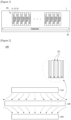
- Figure 3 is a schematic diagram showing a surface coating apparatus (200) of a porous substrate according to the present invention
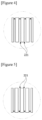
- Figure 4 is an enlarged diagram of Part A in Figure 3
- Figure 5 is an enlarged diagram of Part B in Figure 3 .
- the coating apparatus (200) of the invention is an apparatus for coating a surface of a porous substrate having a first surface (e.g., front surface) and a second surface (e.g., back surface) opposite the first surface.
- the coating apparatus (200) comprises a first supply part (211) for supplying a source gas to a first surface of a porous substrate (220) and a first pumping part (231) for generating a flow current inside the porous substrate (220) in the direction from the first surface of the porous substrate (220) toward the second surface.
- the coating apparatus (200) also comprises a second supply part (212) for supplying a source gas to the second surface of the porous substrate (220) and a second pumping part (232) for generating a flow current inside the porous substrate (220) in the direction from the second surface of the porous substrate (220) toward the first surface.
- the coating apparatus (200) also comprises a substrate carrier (not shown) for transporting the substrate (220).
- the substrate carrier has one or more openings for passing the flow current in at least some regions.
- the substrate carrier may also be configured in the form of a mesh or grill having a predetermined aperture ratio.
- the substrate carrier may also be configured in a roll-to-roll manner to comprise a plurality of guide rolls.
- the roll-to-roll apparatus in order to form openings for passing the flow current, may also be configured so as to support both side edges of the substrate in the width direction.
- the region where the first pumping part (231) and the second supply part (212) are disposed may be referred to as the upper part of the substrate (220), and the region where the first supply part (211) and the second pumping part (232) are disposed may be referred to as the lower part of the substrate (220).
- the first and second supply parts (211, 212) are provided so as to inject the source gas onto the substrate, which comprise one or more source gas (source A, source B) injection ports and purge gas injection ports.
- each of the supply parts may comprise pretreatment gas injection ports, source gas injection ports, and purge gas injection ports.
- a pretreatment gas injection port a first precursor (source A) injection port, a purge gas injection port, a second precursor (source B) injection port, and a purge gas injection port may be arranged.
- the pretreatment gas injection port may have a plurality of different gas injection ports.
- plasma or organic vapor may be supplied through the pretreatment gas injection port.
- the first supply part (211) and the first pumping part (231) may be disposed to face each other on the basis of the substrate (220).
- the first pumping part (231) when the source gas is injected to the first surface side of the substrate through the first supply part (211), the first pumping part (231) generates the flow current directed from the first surface toward the second surface in pores (221) inside the porous substrate, whereby the coating can be achieved inside the pores.
- the second supply part (212) and the second pumping part (232) may be disposed to face each other on the basis of the substrate.
- the second pumping part (232) when the source gas is injected to the second surface side of the substrate (220) through the second supply part (212), the second pumping part (232) generates the flow current directed from the second surface toward the first surface in pores (221) inside the porous substrate, whereby the coating can be achieved inside the pores.
- supply and diffusion of the source gas are smoothly performed on both surfaces (first surface and second surface) of the porous substrate (200) by allowing the direction where the source gas is supplied and the flow current direction (see arrows in Figures 4 and 5 ) formed inside the porous substrate to sequentially pass through different spaces along the transport direction of the porous substrate (220).
- first pumping part (231) and the second pumping part (232) may be provided to form a flow current with the same pressure.
- first pumping part (231) and the second pumping part (232) may also be provided to form a flow current with different pressures.
- the degree of deposition of the porous substrate (220) on both surfaces can be optionally controlled.
- the substrate carrier is provided to transport a discontinuous substrate.
- the discontinuous substrate may be a wafer or glass. Therefore, the coating apparatus (200) further comprises a substrate reverse part (not shown) for reversing the first surface and the second surface of the substrate passing through the first supply part (211).
- the first supply part (211) and the second supply part (212) are disposed in order along the transport direction of the substrate on either the upper part or the lower part of the substrate.
- the first supply part (211) and the second supply part (212) may be disposed together on the upper part of the substrate or on the lower part.
- first pumping part (231) and the second pumping part (232) are disposed in order along the transport direction of the substrate (220) on the other part of the upper part or the lower part of the substrate.
- first pumping part (231) and the second pumping part (232) may be disposed together on the upper part of the substrate (220) or on the lower part.
- first and second supply parts (211, 212) are disposed on the upper part of the substrate (220)
- first pumping part (231) and the second pumping part (232) may be disposed on the lower part of the substrate (220).
- first supply part (211) and the first pumping part (231) may be arranged to face each other on the basis of the substrate (220), and the second supply part (212) and the second pumping part (232) may be arranged to face each other on the basis of the substrate (220).
- the coating method using the coating apparatus (200) having the above structure is as follows.
- the coating method is a method for coating a surface of a porous substrate by using the apparatus in accordance with the invention by generating a flow current inside pores in the porous substrate having a first surface and a second surface opposite to the first surface, which comprises steps of: transporting the porous substrate; supplying and diffusing a source gas in the direction from the first surface of the porous substrate toward the second surface, and removing reactive by-products and the remaining source after the reaction; and supplying and diffusing the source gas in the direction from the second surface of the porous substrate toward the first surface, and removing reactive by-products and the remaining source after the reaction.
- the surface coating method of a porous substrate is a method for coating a surface of a porous substrate having a first surface and a second surface opposite to the first surface, which comprises steps of: transporting the porous substrate; supplying and diffusing a source gas to the first surface of the porous substrate; and generating a flow current inside the porous substrate in the direction from the first surface of the porous substrate toward the second surface.
- the method comprises steps of: supplying and diffusing a source gas to the second surface of the porous substrate; and generating a flow current inside the porous substrate in the direction from the second surface of the porous substrate toward the first surface.
Landscapes
- Chemical & Material Sciences (AREA)
- Engineering & Computer Science (AREA)
- Materials Engineering (AREA)
- Organic Chemistry (AREA)
- General Chemical & Material Sciences (AREA)
- Chemical Kinetics & Catalysis (AREA)
- Mechanical Engineering (AREA)
- Metallurgy (AREA)
- Life Sciences & Earth Sciences (AREA)
- Geochemistry & Mineralogy (AREA)
- Chemical Vapour Deposition (AREA)
- Application Of Or Painting With Fluid Materials (AREA)
Description
- The present invention relates to an apparatus and a method for coating a surface of a porous substrate.
- As a method of forming a film on a substrate, there is, for example, an atomic layer deposition method.
- The atomic layer deposition (ALD) is a technique for forming a film on a substrate based on the sequential use of chemical substances, which are usually in a gas phase, which is applied to various fields.
-
Figure 1 is a schematic diagram showing a general atomic layer deposition apparatus (1), and particularly shows a spatial division type atomic layer deposition apparatus (1). - The atomic layer deposition apparatus (1) comprises a gas distribution plate (10) having a plurality of supply ports (11, 12, 13) and a transport device for transporting a substrate (20). The gas distribution plate (10) has precursor gas supply ports (11, 12) for supplying one or more precursor gases (precursor A, B) (also referred to as 'source gas') onto the substrate (20), and a purge gas supply port (13) for supplying a purge gas.
- In addition, the atomic layer deposition method is advantageous for surface coating of pores in the porous substrate due to its high coatability. However, when the porous substrate becomes thick, supply and diffusion of the source gas into the pores, and purge and removal of reactive by-products are not smooth and thus uniform coating becomes difficult.
- Specifically, depending on the pore size, the aspect ratio, or the surface characteristics of the porous substrate, the gas supply or diffusion into the pores may not be smooth, and accordingly, unevenness of the deposited thickness and composition may occur along the depth direction (thickness direction) of the porous substrate.
- A method for depositing a layer of material on a permeable substrate is disclosed in
US 2014/037853 . The method involves passing the substrate between a set of reactors injecting source precursor, reactant precursor, purge gas or a combination thereof onto the substrate as the substrate passes between the reactors, while part of the gas injected by a reactor penetrates the substrate and is discharged by the other reactor. - It is a problem to be solved by the present invention to provide an apparatus and a method for coating a surface of a porous substrate which can uniformly coat the surface of the porous substrate.
- To solve the above-described problem, according to one aspect of the present invention, there is provided an apparatus for coating a surface of a porous substrate having a first surface and a second surface opposite to the first surface, which comprises: a first supply part for supplying a source gas to the first surface of the porous substrate; a first pumping part for generating a flow current inside the porous substrate in the direction from the first surface of the porous substrate toward the second surface; a second supply part for supplying the source gas to the second surface of the porous substrate; a second pumping part for generating a flow current inside the porous substrate in the direction from the second surface of the porous substrate toward the first surface; and a substrate carrier for transporting the substrate which is provided so as to transport a discontinuous substrate; wherein the first supply part and the second supply part are disposed in order along the transport direction of the substrate on either the upper part or the lower part of the substrate, and the first pumping part and the second pumping part are disposed in order along the transport direction of the substrate on the other part of the upper part or the lower part of the substrate, characterized in that the apparatus comprises a substrate reverse part for reversing the first surface and the second surface of the substrate passing through the first supply part, and the substrate carrier has one or more openings for passing the flow current in at least some regions.
- Also, the first supply part and the first pumping part may be disposed to face each other on the basis of the substrate.
- Furthermore, the second supply part and the second pumping part may be disposed to face each other on the basis of the substrate..
- Furthermore, the first supply part and the second supply part may be arranged in order along the transport direction of the substrate, and the first pumping part and the second pumping part may be arranged in order along the transport direction of the substrate.
- The substrate carrier has one or more openings for passing the flow current in at least some regions. The substrate carrier is provided to discontinuously transport the substrate upon passing through the first and second supply parts.
- Also, the apparatus further comprises a substrate reverse part for reversing the first surface and the second surface of the substrate passing through the first supply part.
- At this time, the first supply part and the second supply part may be disposed on either the upper part or the lower part of the substrate in order along the transport direction of the substrate, and the first pumping part and the second pumping part may be disposed on the other part of the upper part or the lower part of the substrate in order along the transport direction of the substrate.
- In addition, according to another aspect of the present invention, there is provided a method for coating a surface of a porous substrate by using the apparatus of the first aspect of the invention by generating a flow current inside pores in the porous substrate having a first surface and a second surface opposite to the first surface, which comprises steps of: transporting the porous substrate; supplying and diffusing a source gas in the direction from the first surface of the porous substrate toward the second surface, and removing reactive by-products and the remaining source after the reaction; and supplying and diffusing the source gas in the direction from the second surface of the porous substrate toward the first surface, and removing reactive by-products and the remaining source after the reaction.
- As described above, the apparatus and the method for coating a surface of a porous substrate related to at least one embodiment of the present invention have the following effects.
- Supply and diffusion of the source gas are smoothly performed on both surfaces of the porous substrate by allowing the direction where the source gas is supplied and the flow current direction formed inside the porous substrate to sequentially pass through different spaces along the transport direction of the porous substrate, whereby the unevenness of the deposited thickness and composition can be improved.
- Furthermore, the degree of deposition on both surfaces (front surface, back surface) of the porous substrate can be optionally controlled.
-
-
Figure 1 is a schematic diagram showing a general atomic layer deposition apparatus. -
Figure 2 is a schematic diagram showing a surface coating apparatus of a porous substrate which is not in accordance with the present invention. -
Figure 3 is a schematic diagram showing a surface coating apparatus of a porous substrate related to a second embodiment of the present invention. -
Figure 4 is an enlarged diagram of Part A inFigure 3 . -
Figure 5 is an enlarged diagram of Part B inFigure 3 . - Hereinafter, an apparatus and a method for coating a surface of a porous substrate according to one embodiment of the present invention will be described in detail with reference to the accompanying drawings.
- In addition, the same or similar reference numerals are given to the same or corresponding components regardless of reference numerals, of which redundant explanations will be omitted, and for convenience of explanation, the size and shape of each constituent member as shown may be exaggerated or reduced.
- In this document, the surface coating apparatus of a porous substrate (hereinafter, also referred to as `coating apparatus') may be an atomic layer deposition apparatus, but is not limited thereto, which can also be applied to various deposition methods in which coating is performed by formation of a flow current, for example, chemical vapor deposition, molecular layer deposition, or deposition by a combination thereof.
-
Figure 2 is a schematic diagram showing a surface coating apparatus (100) of a porous substrate which is not in accordance with the present invention. - The coating apparatus (100) is an apparatus for coating a surface of a porous substrate having a first surface and a second surface opposite to the first surface, which comprises: a source gas supply part (110) for supplying a source gas to the first surface of the porous substrate (20) and a source gas pumping part (130) for generating a flow current in the porous substrate interior (pores, 121) in the direction from the first surface of the porous substrate (120) toward the second surface.
- Accordingly, the source gas is injected toward the first surface side of the porous substrate (120), and simultaneously the flow current directed from the first surface side toward the second surface side is generated in the pores of the porous substrate (120) through the source gas pumping part (130), whereby injection and diffusion of the source gas into the inside of the porous substrate (120) are smooth.
-
Figure 3 is a schematic diagram showing a surface coating apparatus (200) of a porous substrate according to the present invention,Figure 4 is an enlarged diagram of Part A inFigure 3 , andFigure 5 is an enlarged diagram of Part B inFigure 3 . - The coating apparatus (200) of the invention is an apparatus for coating a surface of a porous substrate having a first surface (e.g., front surface) and a second surface (e.g., back surface) opposite the first surface.
- The coating apparatus (200) comprises a first supply part (211) for supplying a source gas to a first surface of a porous substrate (220) and a first pumping part (231) for generating a flow current inside the porous substrate (220) in the direction from the first surface of the porous substrate (220) toward the second surface.
- The coating apparatus (200) also comprises a second supply part (212) for supplying a source gas to the second surface of the porous substrate (220) and a second pumping part (232) for generating a flow current inside the porous substrate (220) in the direction from the second surface of the porous substrate (220) toward the first surface.
- The coating apparatus (200) also comprises a substrate carrier (not shown) for transporting the substrate (220). At this time, the substrate carrier has one or more openings for passing the flow current in at least some regions. For example, the substrate carrier may also be configured in the form of a mesh or grill having a predetermined aperture ratio. Alternatively, the substrate carrier may also be configured in a roll-to-roll manner to comprise a plurality of guide rolls. In such a structure, in order to form openings for passing the flow current, the roll-to-roll apparatus may also be configured so as to support both side edges of the substrate in the width direction.
- On the other hand, on the basis of
Figure 3 , the region where the first pumping part (231) and the second supply part (212) are disposed may be referred to as the upper part of the substrate (220), and the region where the first supply part (211) and the second pumping part (232) are disposed may be referred to as the lower part of the substrate (220). - The first and second supply parts (211, 212) are provided so as to inject the source gas onto the substrate, which comprise one or more source gas (source A, source B) injection ports and purge gas injection ports.
- Specifically, each of the supply parts (211, 212) may comprise pretreatment gas injection ports, source gas injection ports, and purge gas injection ports. For example, in the supply part, a pretreatment gas injection port, a first precursor (source A) injection port, a purge gas injection port, a second precursor (source B) injection port, and a purge gas injection port may be arranged. In addition, the pretreatment gas injection port may have a plurality of different gas injection ports. Furthermore, plasma or organic vapor may be supplied through the pretreatment gas injection port.
- Also, the first supply part (211) and the first pumping part (231) may be disposed to face each other on the basis of the substrate (220). For example, when the source gas is injected to the first surface side of the substrate through the first supply part (211), the first pumping part (231) generates the flow current directed from the first surface toward the second surface in pores (221) inside the porous substrate, whereby the coating can be achieved inside the pores.
- Furthermore, the second supply part (212) and the second pumping part (232) may be disposed to face each other on the basis of the substrate. For example, when the source gas is injected to the second surface side of the substrate (220) through the second supply part (212), the second pumping part (232) generates the flow current directed from the second surface toward the first surface in pores (221) inside the porous substrate, whereby the coating can be achieved inside the pores.
- Referring to
Figures 3 to 5 , supply and diffusion of the source gas are smoothly performed on both surfaces (first surface and second surface) of the porous substrate (200) by allowing the direction where the source gas is supplied and the flow current direction (see arrows inFigures 4 and 5 ) formed inside the porous substrate to sequentially pass through different spaces along the transport direction of the porous substrate (220). - On the other hand, the first pumping part (231) and the second pumping part (232) may be provided to form a flow current with the same pressure. Alternatively, the first pumping part (231) and the second pumping part (232) may also be provided to form a flow current with different pressures. Thus, the degree of deposition of the porous substrate (220) on both surfaces (front surface, back surface) can be optionally controlled.
- The substrate carrier is provided to transport a discontinuous substrate. The discontinuous substrate may be a wafer or glass. Therefore, the coating apparatus (200) further comprises a substrate reverse part (not shown) for reversing the first surface and the second surface of the substrate passing through the first supply part (211).
- The first supply part (211) and the second supply part (212) are disposed in order along the transport direction of the substrate on either the upper part or the lower part of the substrate. For example, the first supply part (211) and the second supply part (212) may be disposed together on the upper part of the substrate or on the lower part.
- Similarly, the first pumping part (231) and the second pumping part (232) are disposed in order along the transport direction of the substrate (220) on the other part of the upper part or the lower part of the substrate.
- For example, the first pumping part (231) and the second pumping part (232) may be disposed together on the upper part of the substrate (220) or on the lower part. Of course, when the first and second supply parts (211, 212) are disposed on the upper part of the substrate (220), the first pumping part (231) and the second pumping part (232) may be disposed on the lower part of the substrate (220).
- Also, the first supply part (211) and the first pumping part (231) may be arranged to face each other on the basis of the substrate (220), and the second supply part (212) and the second pumping part (232) may be arranged to face each other on the basis of the substrate (220).
- The coating method using the coating apparatus (200) having the above structure is as follows.
- The coating method is a method for coating a surface of a porous substrate by using the apparatus in accordance with the invention by generating a flow current inside pores in the porous substrate having a first surface and a second surface opposite to the first surface, which comprises steps of: transporting the porous substrate; supplying and diffusing a source gas in the direction from the first surface of the porous substrate toward the second surface, and removing reactive by-products and the remaining source after the reaction; and supplying and diffusing the source gas in the direction from the second surface of the porous substrate toward the first surface, and removing reactive by-products and the remaining source after the reaction.
- For example, the surface coating method of a porous substrate is a method for coating a surface of a porous substrate having a first surface and a second surface opposite to the first surface, which comprises steps of: transporting the porous substrate; supplying and diffusing a source gas to the first surface of the porous substrate; and generating a flow current inside the porous substrate in the direction from the first surface of the porous substrate toward the second surface.
- In addition, the method comprises steps of: supplying and diffusing a source gas to the second surface of the porous substrate; and generating a flow current inside the porous substrate in the direction from the second surface of the porous substrate toward the first surface.
- The preferred embodiments of the present invention as described above are disclosed for exemplary purpose, where those skilled in the art having ordinary knowledge for the present invention can make various corrections, modifications and additions within the scope of the present claims.
- According to the surface coating apparatus and method of the porous substrate related to at least one embodiment of the present invention, supply and diffusion of the source gas are smoothly performed on both surfaces of the porous substrate, whereby the unevenness of the deposited thickness and composition can be improved.
Claims (6)
- A coating apparatus (200) for coating a surface of a porous substrate (220) having a first surface and a second surface opposite to the first surface, which comprises:a first supply part (211) for supplying a source gas to the first surface of the porous substrate (220);a first pumping part (231) for generating a flow current inside the porous substrate (220) in the direction from the first surface of the porous substrate (220) toward the second surface;a second supply part (212) for supplying the source gas to the second surface of the porous substrate (220);a second pumping part (232) for generating a flow current inside the porous substrate (220) in the direction from the second surface of the porous substrate (220) toward the first surface; anda substrate carrier for transporting the substrate (220) which is provided so as to transport a discontinuous substrate;wherein the first supply part (211) and the second supply part (212) are disposed in order along the transport direction of the substrate (220) on either the upper part or the lower part of the substrate, and the first pumping part (231) and the second pumping part (232) are disposed in order along the transport direction of the substrate (220) on the other part of the upper part or the lower part of the substrate (220),characterized in thatthe apparatus (200) comprises a substrate reverse part for reversing the first surface and the second surface of the substrate passing through the first supply part (211), andthe substrate carrier has one or more openings for passing the flow current in at least some regions.
- The apparatus (200) for coating a porous substrate (220) according to claim 1,
wherein the first supply part (211) and the first pumping part (231) are disposed to face each other on the basis of the substrate (220). - The apparatus (200) for coating a porous substrate (220) according to claim 1,
wherein the second supply part (212) and the second pumping part (232) are disposed to face each other on the basis of the substrate (220). - The apparatus (200) for coating a porous substrate (220) according to claim 1,wherein the first supply part (211) and the second supply part (212) are arranged in order along the transport direction of the substrate (200), andthe first pumping part (231) and the second pumping part (232) are arranged in order along the transport direction of the substrate.
- The apparatus (200) for coating a porous substrate (220) according to claim 1,
wherein the first supply part (211) comprises pretreatment gas injection ports, source gas injection ports and purge gas injection ports. - A method for coating a surface of a porous substrate by using the apparatus (200) of any of claims 1-5 by generating a flow current inside pores in the porous substrate (220) having a first surface and a second surface opposite to the first surface, which comprises steps of:transporting the porous substrate (220);supplying and diffusing a source gas in the direction from the first surface of the porous substrate (220) toward the second surface, and removing reactive by-products and the remaining source after the reaction; andsupplying and diffusing the source gas in the direction from the second surface of the porous substrate (220) toward the first surface, and removing reactive by-products and the remaining source after the reaction.
Applications Claiming Priority (2)
| Application Number | Priority Date | Filing Date | Title |
|---|---|---|---|
| KR1020170088402A KR102218855B1 (en) | 2017-07-12 | 2017-07-12 | Apparatus and method for coating surface of porous substrate |
| PCT/KR2018/007058 WO2019013465A1 (en) | 2017-07-12 | 2018-06-22 | Device and method for coating surface of porous substrate |
Publications (3)
| Publication Number | Publication Date |
|---|---|
| EP3653750A1 EP3653750A1 (en) | 2020-05-20 |
| EP3653750A4 EP3653750A4 (en) | 2020-07-15 |
| EP3653750B1 true EP3653750B1 (en) | 2024-08-21 |
Family
ID=65001906
Family Applications (1)
| Application Number | Title | Priority Date | Filing Date |
|---|---|---|---|
| EP18831577.4A Active EP3653750B1 (en) | 2017-07-12 | 2018-06-22 | Device and method for coating surface of porous substrate |
Country Status (6)
| Country | Link |
|---|---|
| US (1) | US20200165724A1 (en) |
| EP (1) | EP3653750B1 (en) |
| JP (1) | JP7066960B2 (en) |
| KR (1) | KR102218855B1 (en) |
| CN (1) | CN110770366A (en) |
| WO (1) | WO2019013465A1 (en) |
Families Citing this family (5)
| Publication number | Priority date | Publication date | Assignee | Title |
|---|---|---|---|---|
| CN112048709B (en) * | 2019-06-06 | 2024-03-08 | 皮考逊公司 | Methods of making coated interwoven substrates, coated articles and implantable medical devices |
| FI129040B (en) * | 2019-06-06 | 2021-05-31 | Picosun Oy | Coating of fluid-permeable materials |
| KR102461975B1 (en) * | 2020-10-29 | 2022-11-02 | 주식회사 비이아이랩 | Roll to roll atomic layer deposition apparatus |
| DE102022106876A1 (en) | 2022-03-23 | 2023-09-28 | Technische Universität Dresden, Körperschaft des öffentlichen Rechts | Filter structure as well as its production and use |
| FI20225589A1 (en) * | 2022-06-29 | 2023-12-30 | Beneq Oy | A barrier deposit within a substrate |
Family Cites Families (24)
| Publication number | Priority date | Publication date | Assignee | Title |
|---|---|---|---|---|
| US4466258A (en) * | 1982-01-06 | 1984-08-21 | Sando Iron Works Co., Ltd. | Apparatus for low-temperature plasma treatment of a textile product |
| US4609562A (en) * | 1984-12-20 | 1986-09-02 | Westinghouse Electric Corp. | Apparatus and method for depositing coating onto porous substrate |
| JPH0718451A (en) * | 1993-06-30 | 1995-01-20 | Tokyo Gas Co Ltd | Method and apparatus for forming an oxide film on a porous substrate |
| ATE208700T1 (en) * | 1994-07-22 | 2001-11-15 | Fraunhofer Ges Forschung | METHOD AND DEVICE FOR PLASMA MODIFICATION OF FLAT POROUS OBJECTS |
| DE19646094C2 (en) * | 1996-11-08 | 1999-03-18 | Sintec Keramik Gmbh | Process for chemical gas phase infiltration of refractory substances, in particular carbon and silicon carbide, and use of the process |
| KR100331544B1 (en) * | 1999-01-18 | 2002-04-06 | 윤종용 | Method for introducing gases into a reactor chamber and a shower head used therein |
| ATE350175T1 (en) * | 2000-01-21 | 2007-01-15 | Res Triangle Inst | METHOD FOR PRODUCING THERMALLY AND MECHANICALLY STABLE METAL/POROUS SUBSTRATE COMPOSITE MEMBRANES |
| US20040253377A1 (en) * | 2002-10-24 | 2004-12-16 | Bok Lowell D. | Batch and continuous CVI densification furnace |
| JP2005187114A (en) | 2003-12-25 | 2005-07-14 | Shibaura Mechatronics Corp | Vacuum processing equipment |
| JP4534565B2 (en) | 2004-04-16 | 2010-09-01 | 株式会社デンソー | Method for producing ceramic porous |
| KR101314708B1 (en) * | 2006-03-26 | 2013-10-10 | 로터스 어플라이드 테크놀로지, 엘엘씨 | Atomic layer deposition system and method for coating flexible substrates |
| JP2009288293A (en) | 2008-05-27 | 2009-12-10 | Nisca Corp | Optical filter, method for depositing film of the same and apparatus for adjusting quantity of image pickup light |
| CN101994096B (en) * | 2009-08-14 | 2013-03-20 | 鸿富锦精密工业(深圳)有限公司 | Vacuum film coater |
| JP5681192B2 (en) * | 2009-09-22 | 2015-03-04 | スリーエム イノベイティブ プロパティズ カンパニー | Method for applying atomic layer deposition coatings on porous non-ceramic substrates |
| NL2004177C2 (en) * | 2010-02-01 | 2011-08-03 | Levitech B V | Dynamic fluid valve and method for establishing the same. |
| US20120213947A1 (en) * | 2011-02-18 | 2012-08-23 | Synos Technology, Inc. | Depositing thin layer of material on permeable substrate |
| US20140037853A1 (en) * | 2011-02-18 | 2014-02-06 | Veeco Ald Inc. | Depositing thin layer of material on permeable substrate |
| US20130192761A1 (en) | 2012-01-31 | 2013-08-01 | Joseph Yudovsky | Rotary Substrate Processing System |
| KR20130142869A (en) * | 2012-06-20 | 2013-12-30 | 주식회사 엠티에스나노테크 | Apparatus and method for atomic layer deposition |
| US11326255B2 (en) * | 2013-02-07 | 2022-05-10 | Uchicago Argonne, Llc | ALD reactor for coating porous substrates |
| NL2013739B1 (en) * | 2014-11-04 | 2016-10-04 | Asm Int Nv | Atomic layer deposition apparatus and method for processing substrates using an apparatus. |
| US10548646B2 (en) | 2014-11-24 | 2020-02-04 | FBC Device ApS | Angulating bone plate |
| US20160229758A1 (en) * | 2015-02-11 | 2016-08-11 | United Technologies Corporation | Continuous chemical vapor deposition/infiltration coater |
| KR101820016B1 (en) * | 2015-12-16 | 2018-01-18 | 주식회사 토바 | Non-Contact Roll-To-Roll ALD System using Nip-Roll |
-
2017
- 2017-07-12 KR KR1020170088402A patent/KR102218855B1/en active Active
-
2018
- 2018-06-22 WO PCT/KR2018/007058 patent/WO2019013465A1/en not_active Ceased
- 2018-06-22 US US16/630,124 patent/US20200165724A1/en not_active Abandoned
- 2018-06-22 JP JP2019571250A patent/JP7066960B2/en active Active
- 2018-06-22 EP EP18831577.4A patent/EP3653750B1/en active Active
- 2018-06-22 CN CN201880040649.2A patent/CN110770366A/en active Pending
Also Published As
| Publication number | Publication date |
|---|---|
| CN110770366A (en) | 2020-02-07 |
| WO2019013465A1 (en) | 2019-01-17 |
| KR20190007228A (en) | 2019-01-22 |
| US20200165724A1 (en) | 2020-05-28 |
| EP3653750A4 (en) | 2020-07-15 |
| JP2020524748A (en) | 2020-08-20 |
| JP7066960B2 (en) | 2022-05-16 |
| KR102218855B1 (en) | 2021-02-23 |
| EP3653750A1 (en) | 2020-05-20 |
Similar Documents
| Publication | Publication Date | Title |
|---|---|---|
| EP3653750A1 (en) | Device and method for coating surface of porous substrate | |
| US20150096495A1 (en) | Apparatus and method of atomic layer deposition | |
| US8187679B2 (en) | Radical-enhanced atomic layer deposition system and method | |
| US12125684B2 (en) | Temperature controlled reaction chamber | |
| US9873942B2 (en) | Methods of vapor deposition with multiple vapor sources | |
| KR20120056878A (en) | Vapor deposition reactor for forming thin film on curved surface | |
| TWI725444B (en) | Cyclic epitaxy deposition system and gas distribution module thereof | |
| KR101471973B1 (en) | Atomic layer deposition equipment and its control method | |
| KR102462931B1 (en) | Gas Supply Unit and Substrate Treating Apparatus | |
| KR102070864B1 (en) | Gas supply control method for substrate processing apparatus | |
| Henn-Lecordier et al. | Impact of parasitic reactions on wafer-scale uniformity in water-based and ozone-based atomic layer deposition | |
| CN108456872A (en) | Film deposition apparatus | |
| JP6547271B2 (en) | Deposition method by vapor deposition on flexible substrate | |
| US20200270751A1 (en) | Enclosed-channel reactor system with conduit plate | |
| KR20200086883A (en) | Apparatus of Atomic Layer Deposition | |
| KR101849388B1 (en) | Gas Module for Atomic Layer Deposition Apparatus, Atomic Layer Deposition Apparatus, Deposition Method using the same | |
| KR101559629B1 (en) | Atomic layer deposition apparatus | |
| KR100600051B1 (en) | Atomic layer deposition equipment and ternary thin film formation method using the same | |
| KR102808629B1 (en) | Gas supply unit and substrate processing apparatus including gas supply unit | |
| US12624449B2 (en) | Methods and systems for inhibiting precursor interactions during radical-enhanced atomic layer deposition | |
| US20230265558A1 (en) | Atomic layer deposition apparatus and atomic layer deposition method using the same | |
| KR20120066852A (en) | Thin layer deposition apparatus | |
| US20190062912A1 (en) | Atomic layer deposition for continuous, high-speed thin films | |
| KR20240027992A (en) | Method for preventing particle generation in deposition process | |
| KR20220034991A (en) | Substrate processing apparatus and method of substrate processing |
Legal Events
| Date | Code | Title | Description |
|---|---|---|---|
| STAA | Information on the status of an ep patent application or granted ep patent |
Free format text: STATUS: THE INTERNATIONAL PUBLICATION HAS BEEN MADE |
|
| PUAI | Public reference made under article 153(3) epc to a published international application that has entered the european phase |
Free format text: ORIGINAL CODE: 0009012 |
|
| STAA | Information on the status of an ep patent application or granted ep patent |
Free format text: STATUS: REQUEST FOR EXAMINATION WAS MADE |
|
| 17P | Request for examination filed |
Effective date: 20200212 |
|
| AK | Designated contracting states |
Kind code of ref document: A1 Designated state(s): AL AT BE BG CH CY CZ DE DK EE ES FI FR GB GR HR HU IE IS IT LI LT LU LV MC MK MT NL NO PL PT RO RS SE SI SK SM TR |
|
| AX | Request for extension of the european patent |
Extension state: BA ME |
|
| A4 | Supplementary search report drawn up and despatched |
Effective date: 20200612 |
|
| RIC1 | Information provided on ipc code assigned before grant |
Ipc: C23C 16/44 20060101ALI20200606BHEP Ipc: C23C 16/455 20060101AFI20200606BHEP Ipc: C23C 16/04 20060101ALI20200606BHEP Ipc: C23C 16/54 20060101ALI20200606BHEP Ipc: C03B 35/20 20060101ALI20200606BHEP Ipc: C03C 17/00 20060101ALI20200606BHEP |
|
| DAV | Request for validation of the european patent (deleted) | ||
| DAX | Request for extension of the european patent (deleted) | ||
| STAA | Information on the status of an ep patent application or granted ep patent |
Free format text: STATUS: EXAMINATION IS IN PROGRESS |
|
| 17Q | First examination report despatched |
Effective date: 20220729 |
|
| REG | Reference to a national code |
Ipc: C23C0016540000 Ref country code: DE Ref legal event code: R079 Ref document number: 602018073429 Country of ref document: DE Free format text: PREVIOUS MAIN CLASS: C23C0016455000 |
|
| GRAP | Despatch of communication of intention to grant a patent |
Free format text: ORIGINAL CODE: EPIDOSNIGR1 |
|
| RIC1 | Information provided on ipc code assigned before grant |
Ipc: C23C 16/44 20060101ALI20240229BHEP Ipc: C23C 16/04 20060101ALI20240229BHEP Ipc: C03B 35/20 20060101ALI20240229BHEP Ipc: C03C 17/00 20060101ALI20240229BHEP Ipc: C23C 16/54 20060101AFI20240229BHEP |
|
| STAA | Information on the status of an ep patent application or granted ep patent |
Free format text: STATUS: GRANT OF PATENT IS INTENDED |
|
| RIC1 | Information provided on ipc code assigned before grant |
Ipc: C23C 16/44 20060101ALI20240318BHEP Ipc: C23C 16/04 20060101ALI20240318BHEP Ipc: C23C 16/54 20060101AFI20240318BHEP |
|
| INTG | Intention to grant announced |
Effective date: 20240404 |
|
| GRAS | Grant fee paid |
Free format text: ORIGINAL CODE: EPIDOSNIGR3 |
|
| GRAA | (expected) grant |
Free format text: ORIGINAL CODE: 0009210 |
|
| STAA | Information on the status of an ep patent application or granted ep patent |
Free format text: STATUS: THE PATENT HAS BEEN GRANTED |
|
| AK | Designated contracting states |
Kind code of ref document: B1 Designated state(s): AL AT BE BG CH CY CZ DE DK EE ES FI FR GB GR HR HU IE IS IT LI LT LU LV MC MK MT NL NO PL PT RO RS SE SI SK SM TR |
|
| REG | Reference to a national code |
Ref country code: GB Ref legal event code: FG4D |
|
| REG | Reference to a national code |
Ref country code: CH Ref legal event code: EP |
|
| REG | Reference to a national code |
Ref country code: IE Ref legal event code: FG4D |
|
| REG | Reference to a national code |
Ref country code: DE Ref legal event code: R096 Ref document number: 602018073429 Country of ref document: DE |
|
| REG | Reference to a national code |
Ref country code: LT Ref legal event code: MG9D |
|
| REG | Reference to a national code |
Ref country code: NL Ref legal event code: MP Effective date: 20240821 |
|
| PG25 | Lapsed in a contracting state [announced via postgrant information from national office to epo] |
Ref country code: NO Free format text: LAPSE BECAUSE OF FAILURE TO SUBMIT A TRANSLATION OF THE DESCRIPTION OR TO PAY THE FEE WITHIN THE PRESCRIBED TIME-LIMIT Effective date: 20241121 |
|
| REG | Reference to a national code |
Ref country code: AT Ref legal event code: MK05 Ref document number: 1715545 Country of ref document: AT Kind code of ref document: T Effective date: 20240821 |
|
| PG25 | Lapsed in a contracting state [announced via postgrant information from national office to epo] |
Ref country code: NL Free format text: LAPSE BECAUSE OF FAILURE TO SUBMIT A TRANSLATION OF THE DESCRIPTION OR TO PAY THE FEE WITHIN THE PRESCRIBED TIME-LIMIT Effective date: 20240821 Ref country code: PT Free format text: LAPSE BECAUSE OF FAILURE TO SUBMIT A TRANSLATION OF THE DESCRIPTION OR TO PAY THE FEE WITHIN THE PRESCRIBED TIME-LIMIT Effective date: 20241223 Ref country code: GR Free format text: LAPSE BECAUSE OF FAILURE TO SUBMIT A TRANSLATION OF THE DESCRIPTION OR TO PAY THE FEE WITHIN THE PRESCRIBED TIME-LIMIT Effective date: 20241122 Ref country code: PL Free format text: LAPSE BECAUSE OF FAILURE TO SUBMIT A TRANSLATION OF THE DESCRIPTION OR TO PAY THE FEE WITHIN THE PRESCRIBED TIME-LIMIT Effective date: 20240821 Ref country code: FI Free format text: LAPSE BECAUSE OF FAILURE TO SUBMIT A TRANSLATION OF THE DESCRIPTION OR TO PAY THE FEE WITHIN THE PRESCRIBED TIME-LIMIT Effective date: 20240821 |
|
| PG25 | Lapsed in a contracting state [announced via postgrant information from national office to epo] |
Ref country code: BG Free format text: LAPSE BECAUSE OF FAILURE TO SUBMIT A TRANSLATION OF THE DESCRIPTION OR TO PAY THE FEE WITHIN THE PRESCRIBED TIME-LIMIT Effective date: 20240821 |
|
| PG25 | Lapsed in a contracting state [announced via postgrant information from national office to epo] |
Ref country code: LV Free format text: LAPSE BECAUSE OF FAILURE TO SUBMIT A TRANSLATION OF THE DESCRIPTION OR TO PAY THE FEE WITHIN THE PRESCRIBED TIME-LIMIT Effective date: 20240821 |
|
| PG25 | Lapsed in a contracting state [announced via postgrant information from national office to epo] |
Ref country code: IS Free format text: LAPSE BECAUSE OF FAILURE TO SUBMIT A TRANSLATION OF THE DESCRIPTION OR TO PAY THE FEE WITHIN THE PRESCRIBED TIME-LIMIT Effective date: 20241221 Ref country code: AT Free format text: LAPSE BECAUSE OF FAILURE TO SUBMIT A TRANSLATION OF THE DESCRIPTION OR TO PAY THE FEE WITHIN THE PRESCRIBED TIME-LIMIT Effective date: 20240821 |
|
| PG25 | Lapsed in a contracting state [announced via postgrant information from national office to epo] |
Ref country code: HR Free format text: LAPSE BECAUSE OF FAILURE TO SUBMIT A TRANSLATION OF THE DESCRIPTION OR TO PAY THE FEE WITHIN THE PRESCRIBED TIME-LIMIT Effective date: 20240821 |
|
| PG25 | Lapsed in a contracting state [announced via postgrant information from national office to epo] |
Ref country code: ES Free format text: LAPSE BECAUSE OF FAILURE TO SUBMIT A TRANSLATION OF THE DESCRIPTION OR TO PAY THE FEE WITHIN THE PRESCRIBED TIME-LIMIT Effective date: 20240821 Ref country code: RS Free format text: LAPSE BECAUSE OF FAILURE TO SUBMIT A TRANSLATION OF THE DESCRIPTION OR TO PAY THE FEE WITHIN THE PRESCRIBED TIME-LIMIT Effective date: 20241121 |
|
| PG25 | Lapsed in a contracting state [announced via postgrant information from national office to epo] |
Ref country code: RS Free format text: LAPSE BECAUSE OF FAILURE TO SUBMIT A TRANSLATION OF THE DESCRIPTION OR TO PAY THE FEE WITHIN THE PRESCRIBED TIME-LIMIT Effective date: 20241121 Ref country code: PT Free format text: LAPSE BECAUSE OF FAILURE TO SUBMIT A TRANSLATION OF THE DESCRIPTION OR TO PAY THE FEE WITHIN THE PRESCRIBED TIME-LIMIT Effective date: 20241223 Ref country code: PL Free format text: LAPSE BECAUSE OF FAILURE TO SUBMIT A TRANSLATION OF THE DESCRIPTION OR TO PAY THE FEE WITHIN THE PRESCRIBED TIME-LIMIT Effective date: 20240821 Ref country code: NO Free format text: LAPSE BECAUSE OF FAILURE TO SUBMIT A TRANSLATION OF THE DESCRIPTION OR TO PAY THE FEE WITHIN THE PRESCRIBED TIME-LIMIT Effective date: 20241121 Ref country code: NL Free format text: LAPSE BECAUSE OF FAILURE TO SUBMIT A TRANSLATION OF THE DESCRIPTION OR TO PAY THE FEE WITHIN THE PRESCRIBED TIME-LIMIT Effective date: 20240821 Ref country code: LV Free format text: LAPSE BECAUSE OF FAILURE TO SUBMIT A TRANSLATION OF THE DESCRIPTION OR TO PAY THE FEE WITHIN THE PRESCRIBED TIME-LIMIT Effective date: 20240821 Ref country code: IS Free format text: LAPSE BECAUSE OF FAILURE TO SUBMIT A TRANSLATION OF THE DESCRIPTION OR TO PAY THE FEE WITHIN THE PRESCRIBED TIME-LIMIT Effective date: 20241221 Ref country code: HR Free format text: LAPSE BECAUSE OF FAILURE TO SUBMIT A TRANSLATION OF THE DESCRIPTION OR TO PAY THE FEE WITHIN THE PRESCRIBED TIME-LIMIT Effective date: 20240821 Ref country code: GR Free format text: LAPSE BECAUSE OF FAILURE TO SUBMIT A TRANSLATION OF THE DESCRIPTION OR TO PAY THE FEE WITHIN THE PRESCRIBED TIME-LIMIT Effective date: 20241122 Ref country code: FI Free format text: LAPSE BECAUSE OF FAILURE TO SUBMIT A TRANSLATION OF THE DESCRIPTION OR TO PAY THE FEE WITHIN THE PRESCRIBED TIME-LIMIT Effective date: 20240821 Ref country code: ES Free format text: LAPSE BECAUSE OF FAILURE TO SUBMIT A TRANSLATION OF THE DESCRIPTION OR TO PAY THE FEE WITHIN THE PRESCRIBED TIME-LIMIT Effective date: 20240821 Ref country code: BG Free format text: LAPSE BECAUSE OF FAILURE TO SUBMIT A TRANSLATION OF THE DESCRIPTION OR TO PAY THE FEE WITHIN THE PRESCRIBED TIME-LIMIT Effective date: 20240821 Ref country code: AT Free format text: LAPSE BECAUSE OF FAILURE TO SUBMIT A TRANSLATION OF THE DESCRIPTION OR TO PAY THE FEE WITHIN THE PRESCRIBED TIME-LIMIT Effective date: 20240821 |
|
| PG25 | Lapsed in a contracting state [announced via postgrant information from national office to epo] |
Ref country code: DK Free format text: LAPSE BECAUSE OF FAILURE TO SUBMIT A TRANSLATION OF THE DESCRIPTION OR TO PAY THE FEE WITHIN THE PRESCRIBED TIME-LIMIT Effective date: 20240821 Ref country code: SM Free format text: LAPSE BECAUSE OF FAILURE TO SUBMIT A TRANSLATION OF THE DESCRIPTION OR TO PAY THE FEE WITHIN THE PRESCRIBED TIME-LIMIT Effective date: 20240821 Ref country code: RO Free format text: LAPSE BECAUSE OF FAILURE TO SUBMIT A TRANSLATION OF THE DESCRIPTION OR TO PAY THE FEE WITHIN THE PRESCRIBED TIME-LIMIT Effective date: 20240821 |
|
| PG25 | Lapsed in a contracting state [announced via postgrant information from national office to epo] |
Ref country code: EE Free format text: LAPSE BECAUSE OF FAILURE TO SUBMIT A TRANSLATION OF THE DESCRIPTION OR TO PAY THE FEE WITHIN THE PRESCRIBED TIME-LIMIT Effective date: 20240821 |
|
| PG25 | Lapsed in a contracting state [announced via postgrant information from national office to epo] |
Ref country code: CZ Free format text: LAPSE BECAUSE OF FAILURE TO SUBMIT A TRANSLATION OF THE DESCRIPTION OR TO PAY THE FEE WITHIN THE PRESCRIBED TIME-LIMIT Effective date: 20240821 |
|
| PG25 | Lapsed in a contracting state [announced via postgrant information from national office to epo] |
Ref country code: IT Free format text: LAPSE BECAUSE OF FAILURE TO SUBMIT A TRANSLATION OF THE DESCRIPTION OR TO PAY THE FEE WITHIN THE PRESCRIBED TIME-LIMIT Effective date: 20240821 Ref country code: SK Free format text: LAPSE BECAUSE OF FAILURE TO SUBMIT A TRANSLATION OF THE DESCRIPTION OR TO PAY THE FEE WITHIN THE PRESCRIBED TIME-LIMIT Effective date: 20240821 |
|
| REG | Reference to a national code |
Ref country code: DE Ref legal event code: R097 Ref document number: 602018073429 Country of ref document: DE |
|
| PLBE | No opposition filed within time limit |
Free format text: ORIGINAL CODE: 0009261 |
|
| STAA | Information on the status of an ep patent application or granted ep patent |
Free format text: STATUS: NO OPPOSITION FILED WITHIN TIME LIMIT |
|
| PGFP | Annual fee paid to national office [announced via postgrant information from national office to epo] |
Ref country code: DE Payment date: 20250520 Year of fee payment: 8 |
|
| 26N | No opposition filed |
Effective date: 20250522 |
|
| PG25 | Lapsed in a contracting state [announced via postgrant information from national office to epo] |
Ref country code: SE Free format text: LAPSE BECAUSE OF FAILURE TO SUBMIT A TRANSLATION OF THE DESCRIPTION OR TO PAY THE FEE WITHIN THE PRESCRIBED TIME-LIMIT Effective date: 20240821 |
|
| REG | Reference to a national code |
Ref country code: CH Ref legal event code: H13 Free format text: ST27 STATUS EVENT CODE: U-0-0-H10-H13 (AS PROVIDED BY THE NATIONAL OFFICE) Effective date: 20260127 |
|
| PG25 | Lapsed in a contracting state [announced via postgrant information from national office to epo] |
Ref country code: MC Free format text: LAPSE BECAUSE OF FAILURE TO SUBMIT A TRANSLATION OF THE DESCRIPTION OR TO PAY THE FEE WITHIN THE PRESCRIBED TIME-LIMIT Effective date: 20240821 |
|
| PG25 | Lapsed in a contracting state [announced via postgrant information from national office to epo] |
Ref country code: LU Free format text: LAPSE BECAUSE OF NON-PAYMENT OF DUE FEES Effective date: 20250622 |
|
| GBPC | Gb: european patent ceased through non-payment of renewal fee |
Effective date: 20250622 |
|
| REG | Reference to a national code |
Ref country code: BE Ref legal event code: MM Effective date: 20250630 |
|
| PG25 | Lapsed in a contracting state [announced via postgrant information from national office to epo] |
Ref country code: GB Free format text: LAPSE BECAUSE OF NON-PAYMENT OF DUE FEES Effective date: 20250622 |
|
| PG25 | Lapsed in a contracting state [announced via postgrant information from national office to epo] |
Ref country code: IE Free format text: LAPSE BECAUSE OF NON-PAYMENT OF DUE FEES Effective date: 20250622 |
|
| PG25 | Lapsed in a contracting state [announced via postgrant information from national office to epo] |
Ref country code: BE Free format text: LAPSE BECAUSE OF NON-PAYMENT OF DUE FEES Effective date: 20250630 |
|
| PG25 | Lapsed in a contracting state [announced via postgrant information from national office to epo] |
Ref country code: FR Free format text: LAPSE BECAUSE OF NON-PAYMENT OF DUE FEES Effective date: 20250630 |
|
| PG25 | Lapsed in a contracting state [announced via postgrant information from national office to epo] |
Ref country code: CH Free format text: LAPSE BECAUSE OF NON-PAYMENT OF DUE FEES Effective date: 20250630 |