EP3653440B1 - Control method of an autonomous vehicle - Google Patents
Control method of an autonomous vehicle Download PDFInfo
- Publication number
- EP3653440B1 EP3653440B1 EP18248167.1A EP18248167A EP3653440B1 EP 3653440 B1 EP3653440 B1 EP 3653440B1 EP 18248167 A EP18248167 A EP 18248167A EP 3653440 B1 EP3653440 B1 EP 3653440B1
- Authority
- EP
- European Patent Office
- Prior art keywords
- pedestrian
- unit
- image
- road
- autonomous vehicle
- Prior art date
- Legal status (The legal status is an assumption and is not a legal conclusion. Google has not performed a legal analysis and makes no representation as to the accuracy of the status listed.)
- Active
Links
- 238000000034 method Methods 0.000 title claims description 33
- 238000005259 measurement Methods 0.000 claims description 43
- 230000001678 irradiating effect Effects 0.000 claims description 10
- 238000012546 transfer Methods 0.000 description 11
- 238000013459 approach Methods 0.000 description 7
- 239000004973 liquid crystal related substance Substances 0.000 description 4
- 238000012545 processing Methods 0.000 description 3
- 238000007792 addition Methods 0.000 description 1
- 238000001514 detection method Methods 0.000 description 1
- 238000010191 image analysis Methods 0.000 description 1
- 230000001939 inductive effect Effects 0.000 description 1
- 238000012986 modification Methods 0.000 description 1
- 230000004048 modification Effects 0.000 description 1
- 239000013307 optical fiber Substances 0.000 description 1
- 229910052710 silicon Inorganic materials 0.000 description 1
- 239000010703 silicon Substances 0.000 description 1
- 238000006467 substitution reaction Methods 0.000 description 1
Images


Classifications
-
- B—PERFORMING OPERATIONS; TRANSPORTING
- B60—VEHICLES IN GENERAL
- B60W—CONJOINT CONTROL OF VEHICLE SUB-UNITS OF DIFFERENT TYPE OR DIFFERENT FUNCTION; CONTROL SYSTEMS SPECIALLY ADAPTED FOR HYBRID VEHICLES; ROAD VEHICLE DRIVE CONTROL SYSTEMS FOR PURPOSES NOT RELATED TO THE CONTROL OF A PARTICULAR SUB-UNIT
- B60W60/00—Drive control systems specially adapted for autonomous road vehicles
- B60W60/001—Planning or execution of driving tasks
- B60W60/0025—Planning or execution of driving tasks specially adapted for specific operations
-
- B—PERFORMING OPERATIONS; TRANSPORTING
- B60—VEHICLES IN GENERAL
- B60Q—ARRANGEMENT OF SIGNALLING OR LIGHTING DEVICES, THE MOUNTING OR SUPPORTING THEREOF OR CIRCUITS THEREFOR, FOR VEHICLES IN GENERAL
- B60Q1/00—Arrangement of optical signalling or lighting devices, the mounting or supporting thereof or circuits therefor
- B60Q1/02—Arrangement of optical signalling or lighting devices, the mounting or supporting thereof or circuits therefor the devices being primarily intended to illuminate the way ahead or to illuminate other areas of way or environments
- B60Q1/04—Arrangement of optical signalling or lighting devices, the mounting or supporting thereof or circuits therefor the devices being primarily intended to illuminate the way ahead or to illuminate other areas of way or environments the devices being headlights
- B60Q1/06—Arrangement of optical signalling or lighting devices, the mounting or supporting thereof or circuits therefor the devices being primarily intended to illuminate the way ahead or to illuminate other areas of way or environments the devices being headlights adjustable, e.g. remotely-controlled from inside vehicle
- B60Q1/08—Arrangement of optical signalling or lighting devices, the mounting or supporting thereof or circuits therefor the devices being primarily intended to illuminate the way ahead or to illuminate other areas of way or environments the devices being headlights adjustable, e.g. remotely-controlled from inside vehicle automatically
- B60Q1/085—Arrangement of optical signalling or lighting devices, the mounting or supporting thereof or circuits therefor the devices being primarily intended to illuminate the way ahead or to illuminate other areas of way or environments the devices being headlights adjustable, e.g. remotely-controlled from inside vehicle automatically due to special conditions, e.g. adverse weather, type of road, badly illuminated road signs or potential dangers
-
- B—PERFORMING OPERATIONS; TRANSPORTING
- B60—VEHICLES IN GENERAL
- B60K—ARRANGEMENT OR MOUNTING OF PROPULSION UNITS OR OF TRANSMISSIONS IN VEHICLES; ARRANGEMENT OR MOUNTING OF PLURAL DIVERSE PRIME-MOVERS IN VEHICLES; AUXILIARY DRIVES FOR VEHICLES; INSTRUMENTATION OR DASHBOARDS FOR VEHICLES; ARRANGEMENTS IN CONNECTION WITH COOLING, AIR INTAKE, GAS EXHAUST OR FUEL SUPPLY OF PROPULSION UNITS IN VEHICLES
- B60K35/00—Instruments specially adapted for vehicles; Arrangement of instruments in or on vehicles
- B60K35/20—Output arrangements, i.e. from vehicle to user, associated with vehicle functions or specially adapted therefor
- B60K35/28—Output arrangements, i.e. from vehicle to user, associated with vehicle functions or specially adapted therefor characterised by the type of the output information, e.g. video entertainment or vehicle dynamics information; characterised by the purpose of the output information, e.g. for attracting the attention of the driver
-
- B—PERFORMING OPERATIONS; TRANSPORTING
- B60—VEHICLES IN GENERAL
- B60Q—ARRANGEMENT OF SIGNALLING OR LIGHTING DEVICES, THE MOUNTING OR SUPPORTING THEREOF OR CIRCUITS THEREFOR, FOR VEHICLES IN GENERAL
- B60Q1/00—Arrangement of optical signalling or lighting devices, the mounting or supporting thereof or circuits therefor
- B60Q1/02—Arrangement of optical signalling or lighting devices, the mounting or supporting thereof or circuits therefor the devices being primarily intended to illuminate the way ahead or to illuminate other areas of way or environments
- B60Q1/24—Arrangement of optical signalling or lighting devices, the mounting or supporting thereof or circuits therefor the devices being primarily intended to illuminate the way ahead or to illuminate other areas of way or environments for lighting other areas than only the way ahead
-
- B—PERFORMING OPERATIONS; TRANSPORTING
- B60—VEHICLES IN GENERAL
- B60Q—ARRANGEMENT OF SIGNALLING OR LIGHTING DEVICES, THE MOUNTING OR SUPPORTING THEREOF OR CIRCUITS THEREFOR, FOR VEHICLES IN GENERAL
- B60Q1/00—Arrangement of optical signalling or lighting devices, the mounting or supporting thereof or circuits therefor
- B60Q1/26—Arrangement of optical signalling or lighting devices, the mounting or supporting thereof or circuits therefor the devices being primarily intended to indicate the vehicle, or parts thereof, or to give signals, to other traffic
- B60Q1/50—Arrangement of optical signalling or lighting devices, the mounting or supporting thereof or circuits therefor the devices being primarily intended to indicate the vehicle, or parts thereof, or to give signals, to other traffic for indicating other intentions or conditions, e.g. request for waiting or overtaking
- B60Q1/503—Arrangement of optical signalling or lighting devices, the mounting or supporting thereof or circuits therefor the devices being primarily intended to indicate the vehicle, or parts thereof, or to give signals, to other traffic for indicating other intentions or conditions, e.g. request for waiting or overtaking using luminous text or symbol displays in or on the vehicle, e.g. static text
- B60Q1/5035—Arrangement of optical signalling or lighting devices, the mounting or supporting thereof or circuits therefor the devices being primarily intended to indicate the vehicle, or parts thereof, or to give signals, to other traffic for indicating other intentions or conditions, e.g. request for waiting or overtaking using luminous text or symbol displays in or on the vehicle, e.g. static text electronic displays
- B60Q1/5037—Arrangement of optical signalling or lighting devices, the mounting or supporting thereof or circuits therefor the devices being primarily intended to indicate the vehicle, or parts thereof, or to give signals, to other traffic for indicating other intentions or conditions, e.g. request for waiting or overtaking using luminous text or symbol displays in or on the vehicle, e.g. static text electronic displays the display content changing automatically, e.g. depending on traffic situation
-
- B—PERFORMING OPERATIONS; TRANSPORTING
- B60—VEHICLES IN GENERAL
- B60Q—ARRANGEMENT OF SIGNALLING OR LIGHTING DEVICES, THE MOUNTING OR SUPPORTING THEREOF OR CIRCUITS THEREFOR, FOR VEHICLES IN GENERAL
- B60Q1/00—Arrangement of optical signalling or lighting devices, the mounting or supporting thereof or circuits therefor
- B60Q1/26—Arrangement of optical signalling or lighting devices, the mounting or supporting thereof or circuits therefor the devices being primarily intended to indicate the vehicle, or parts thereof, or to give signals, to other traffic
- B60Q1/50—Arrangement of optical signalling or lighting devices, the mounting or supporting thereof or circuits therefor the devices being primarily intended to indicate the vehicle, or parts thereof, or to give signals, to other traffic for indicating other intentions or conditions, e.g. request for waiting or overtaking
- B60Q1/507—Arrangement of optical signalling or lighting devices, the mounting or supporting thereof or circuits therefor the devices being primarily intended to indicate the vehicle, or parts thereof, or to give signals, to other traffic for indicating other intentions or conditions, e.g. request for waiting or overtaking specific to autonomous vehicles
-
- B—PERFORMING OPERATIONS; TRANSPORTING
- B60—VEHICLES IN GENERAL
- B60Q—ARRANGEMENT OF SIGNALLING OR LIGHTING DEVICES, THE MOUNTING OR SUPPORTING THEREOF OR CIRCUITS THEREFOR, FOR VEHICLES IN GENERAL
- B60Q1/00—Arrangement of optical signalling or lighting devices, the mounting or supporting thereof or circuits therefor
- B60Q1/26—Arrangement of optical signalling or lighting devices, the mounting or supporting thereof or circuits therefor the devices being primarily intended to indicate the vehicle, or parts thereof, or to give signals, to other traffic
- B60Q1/50—Arrangement of optical signalling or lighting devices, the mounting or supporting thereof or circuits therefor the devices being primarily intended to indicate the vehicle, or parts thereof, or to give signals, to other traffic for indicating other intentions or conditions, e.g. request for waiting or overtaking
- B60Q1/525—Arrangement of optical signalling or lighting devices, the mounting or supporting thereof or circuits therefor the devices being primarily intended to indicate the vehicle, or parts thereof, or to give signals, to other traffic for indicating other intentions or conditions, e.g. request for waiting or overtaking automatically indicating risk of collision between vehicles in traffic or with pedestrians, e.g. after risk assessment using the vehicle sensor data
-
- B—PERFORMING OPERATIONS; TRANSPORTING
- B60—VEHICLES IN GENERAL
- B60Q—ARRANGEMENT OF SIGNALLING OR LIGHTING DEVICES, THE MOUNTING OR SUPPORTING THEREOF OR CIRCUITS THEREFOR, FOR VEHICLES IN GENERAL
- B60Q1/00—Arrangement of optical signalling or lighting devices, the mounting or supporting thereof or circuits therefor
- B60Q1/26—Arrangement of optical signalling or lighting devices, the mounting or supporting thereof or circuits therefor the devices being primarily intended to indicate the vehicle, or parts thereof, or to give signals, to other traffic
- B60Q1/50—Arrangement of optical signalling or lighting devices, the mounting or supporting thereof or circuits therefor the devices being primarily intended to indicate the vehicle, or parts thereof, or to give signals, to other traffic for indicating other intentions or conditions, e.g. request for waiting or overtaking
- B60Q1/543—Arrangement of optical signalling or lighting devices, the mounting or supporting thereof or circuits therefor the devices being primarily intended to indicate the vehicle, or parts thereof, or to give signals, to other traffic for indicating other intentions or conditions, e.g. request for waiting or overtaking for indicating other states or conditions of the vehicle
-
- B—PERFORMING OPERATIONS; TRANSPORTING
- B60—VEHICLES IN GENERAL
- B60Q—ARRANGEMENT OF SIGNALLING OR LIGHTING DEVICES, THE MOUNTING OR SUPPORTING THEREOF OR CIRCUITS THEREFOR, FOR VEHICLES IN GENERAL
- B60Q1/00—Arrangement of optical signalling or lighting devices, the mounting or supporting thereof or circuits therefor
- B60Q1/26—Arrangement of optical signalling or lighting devices, the mounting or supporting thereof or circuits therefor the devices being primarily intended to indicate the vehicle, or parts thereof, or to give signals, to other traffic
- B60Q1/50—Arrangement of optical signalling or lighting devices, the mounting or supporting thereof or circuits therefor the devices being primarily intended to indicate the vehicle, or parts thereof, or to give signals, to other traffic for indicating other intentions or conditions, e.g. request for waiting or overtaking
- B60Q1/547—Arrangement of optical signalling or lighting devices, the mounting or supporting thereof or circuits therefor the devices being primarily intended to indicate the vehicle, or parts thereof, or to give signals, to other traffic for indicating other intentions or conditions, e.g. request for waiting or overtaking for issuing requests to other traffic participants; for confirming to other traffic participants they can proceed, e.g. they can overtake
-
- B—PERFORMING OPERATIONS; TRANSPORTING
- B60—VEHICLES IN GENERAL
- B60R—VEHICLES, VEHICLE FITTINGS, OR VEHICLE PARTS, NOT OTHERWISE PROVIDED FOR
- B60R21/00—Arrangements or fittings on vehicles for protecting or preventing injuries to occupants or pedestrians in case of accidents or other traffic risks
- B60R21/34—Protecting non-occupants of a vehicle, e.g. pedestrians
-
- B—PERFORMING OPERATIONS; TRANSPORTING
- B60—VEHICLES IN GENERAL
- B60W—CONJOINT CONTROL OF VEHICLE SUB-UNITS OF DIFFERENT TYPE OR DIFFERENT FUNCTION; CONTROL SYSTEMS SPECIALLY ADAPTED FOR HYBRID VEHICLES; ROAD VEHICLE DRIVE CONTROL SYSTEMS FOR PURPOSES NOT RELATED TO THE CONTROL OF A PARTICULAR SUB-UNIT
- B60W30/00—Purposes of road vehicle drive control systems not related to the control of a particular sub-unit, e.g. of systems using conjoint control of vehicle sub-units
- B60W30/14—Adaptive cruise control
-
- B—PERFORMING OPERATIONS; TRANSPORTING
- B60—VEHICLES IN GENERAL
- B60W—CONJOINT CONTROL OF VEHICLE SUB-UNITS OF DIFFERENT TYPE OR DIFFERENT FUNCTION; CONTROL SYSTEMS SPECIALLY ADAPTED FOR HYBRID VEHICLES; ROAD VEHICLE DRIVE CONTROL SYSTEMS FOR PURPOSES NOT RELATED TO THE CONTROL OF A PARTICULAR SUB-UNIT
- B60W40/00—Estimation or calculation of non-directly measurable driving parameters for road vehicle drive control systems not related to the control of a particular sub unit, e.g. by using mathematical models
- B60W40/02—Estimation or calculation of non-directly measurable driving parameters for road vehicle drive control systems not related to the control of a particular sub unit, e.g. by using mathematical models related to ambient conditions
-
- B—PERFORMING OPERATIONS; TRANSPORTING
- B60—VEHICLES IN GENERAL
- B60W—CONJOINT CONTROL OF VEHICLE SUB-UNITS OF DIFFERENT TYPE OR DIFFERENT FUNCTION; CONTROL SYSTEMS SPECIALLY ADAPTED FOR HYBRID VEHICLES; ROAD VEHICLE DRIVE CONTROL SYSTEMS FOR PURPOSES NOT RELATED TO THE CONTROL OF A PARTICULAR SUB-UNIT
- B60W40/00—Estimation or calculation of non-directly measurable driving parameters for road vehicle drive control systems not related to the control of a particular sub unit, e.g. by using mathematical models
- B60W40/08—Estimation or calculation of non-directly measurable driving parameters for road vehicle drive control systems not related to the control of a particular sub unit, e.g. by using mathematical models related to drivers or passengers
-
- B—PERFORMING OPERATIONS; TRANSPORTING
- B60—VEHICLES IN GENERAL
- B60W—CONJOINT CONTROL OF VEHICLE SUB-UNITS OF DIFFERENT TYPE OR DIFFERENT FUNCTION; CONTROL SYSTEMS SPECIALLY ADAPTED FOR HYBRID VEHICLES; ROAD VEHICLE DRIVE CONTROL SYSTEMS FOR PURPOSES NOT RELATED TO THE CONTROL OF A PARTICULAR SUB-UNIT
- B60W50/00—Details of control systems for road vehicle drive control not related to the control of a particular sub-unit, e.g. process diagnostic or vehicle driver interfaces
- B60W50/08—Interaction between the driver and the control system
- B60W50/14—Means for informing the driver, warning the driver or prompting a driver intervention
-
- G—PHYSICS
- G05—CONTROLLING; REGULATING
- G05D—SYSTEMS FOR CONTROLLING OR REGULATING NON-ELECTRIC VARIABLES
- G05D1/00—Control of position, course, altitude or attitude of land, water, air or space vehicles, e.g. using automatic pilots
- G05D1/02—Control of position or course in two dimensions
- G05D1/021—Control of position or course in two dimensions specially adapted to land vehicles
- G05D1/0231—Control of position or course in two dimensions specially adapted to land vehicles using optical position detecting means
- G05D1/0246—Control of position or course in two dimensions specially adapted to land vehicles using optical position detecting means using a video camera in combination with image processing means
-
- G—PHYSICS
- G06—COMPUTING; CALCULATING OR COUNTING
- G06V—IMAGE OR VIDEO RECOGNITION OR UNDERSTANDING
- G06V20/00—Scenes; Scene-specific elements
- G06V20/50—Context or environment of the image
- G06V20/56—Context or environment of the image exterior to a vehicle by using sensors mounted on the vehicle
- G06V20/58—Recognition of moving objects or obstacles, e.g. vehicles or pedestrians; Recognition of traffic objects, e.g. traffic signs, traffic lights or roads
-
- G—PHYSICS
- G06—COMPUTING; CALCULATING OR COUNTING
- G06V—IMAGE OR VIDEO RECOGNITION OR UNDERSTANDING
- G06V40/00—Recognition of biometric, human-related or animal-related patterns in image or video data
- G06V40/10—Human or animal bodies, e.g. vehicle occupants or pedestrians; Body parts, e.g. hands
-
- B—PERFORMING OPERATIONS; TRANSPORTING
- B60—VEHICLES IN GENERAL
- B60Q—ARRANGEMENT OF SIGNALLING OR LIGHTING DEVICES, THE MOUNTING OR SUPPORTING THEREOF OR CIRCUITS THEREFOR, FOR VEHICLES IN GENERAL
- B60Q2300/00—Indexing codes for automatically adjustable headlamps or automatically dimmable headlamps
- B60Q2300/40—Indexing codes relating to other road users or special conditions
- B60Q2300/45—Special conditions, e.g. pedestrians, road signs or potential dangers
-
- B—PERFORMING OPERATIONS; TRANSPORTING
- B60—VEHICLES IN GENERAL
- B60Q—ARRANGEMENT OF SIGNALLING OR LIGHTING DEVICES, THE MOUNTING OR SUPPORTING THEREOF OR CIRCUITS THEREFOR, FOR VEHICLES IN GENERAL
- B60Q2400/00—Special features or arrangements of exterior signal lamps for vehicles
- B60Q2400/50—Projected symbol or information, e.g. onto the road or car body
-
- B—PERFORMING OPERATIONS; TRANSPORTING
- B60—VEHICLES IN GENERAL
- B60R—VEHICLES, VEHICLE FITTINGS, OR VEHICLE PARTS, NOT OTHERWISE PROVIDED FOR
- B60R21/00—Arrangements or fittings on vehicles for protecting or preventing injuries to occupants or pedestrians in case of accidents or other traffic risks
- B60R2021/003—Arrangements or fittings on vehicles for protecting or preventing injuries to occupants or pedestrians in case of accidents or other traffic risks characterised by occupant or pedestian
-
- B—PERFORMING OPERATIONS; TRANSPORTING
- B60—VEHICLES IN GENERAL
- B60W—CONJOINT CONTROL OF VEHICLE SUB-UNITS OF DIFFERENT TYPE OR DIFFERENT FUNCTION; CONTROL SYSTEMS SPECIALLY ADAPTED FOR HYBRID VEHICLES; ROAD VEHICLE DRIVE CONTROL SYSTEMS FOR PURPOSES NOT RELATED TO THE CONTROL OF A PARTICULAR SUB-UNIT
- B60W40/00—Estimation or calculation of non-directly measurable driving parameters for road vehicle drive control systems not related to the control of a particular sub unit, e.g. by using mathematical models
- B60W40/08—Estimation or calculation of non-directly measurable driving parameters for road vehicle drive control systems not related to the control of a particular sub unit, e.g. by using mathematical models related to drivers or passengers
- B60W2040/0809—Driver authorisation; Driver identity check
-
- B—PERFORMING OPERATIONS; TRANSPORTING
- B60—VEHICLES IN GENERAL
- B60W—CONJOINT CONTROL OF VEHICLE SUB-UNITS OF DIFFERENT TYPE OR DIFFERENT FUNCTION; CONTROL SYSTEMS SPECIALLY ADAPTED FOR HYBRID VEHICLES; ROAD VEHICLE DRIVE CONTROL SYSTEMS FOR PURPOSES NOT RELATED TO THE CONTROL OF A PARTICULAR SUB-UNIT
- B60W50/00—Details of control systems for road vehicle drive control not related to the control of a particular sub-unit, e.g. process diagnostic or vehicle driver interfaces
- B60W50/08—Interaction between the driver and the control system
- B60W50/14—Means for informing the driver, warning the driver or prompting a driver intervention
- B60W2050/146—Display means
-
- B—PERFORMING OPERATIONS; TRANSPORTING
- B60—VEHICLES IN GENERAL
- B60W—CONJOINT CONTROL OF VEHICLE SUB-UNITS OF DIFFERENT TYPE OR DIFFERENT FUNCTION; CONTROL SYSTEMS SPECIALLY ADAPTED FOR HYBRID VEHICLES; ROAD VEHICLE DRIVE CONTROL SYSTEMS FOR PURPOSES NOT RELATED TO THE CONTROL OF A PARTICULAR SUB-UNIT
- B60W2420/00—Indexing codes relating to the type of sensors based on the principle of their operation
- B60W2420/40—Photo, light or radio wave sensitive means, e.g. infrared sensors
- B60W2420/403—Image sensing, e.g. optical camera
-
- B—PERFORMING OPERATIONS; TRANSPORTING
- B60—VEHICLES IN GENERAL
- B60W—CONJOINT CONTROL OF VEHICLE SUB-UNITS OF DIFFERENT TYPE OR DIFFERENT FUNCTION; CONTROL SYSTEMS SPECIALLY ADAPTED FOR HYBRID VEHICLES; ROAD VEHICLE DRIVE CONTROL SYSTEMS FOR PURPOSES NOT RELATED TO THE CONTROL OF A PARTICULAR SUB-UNIT
- B60W2554/00—Input parameters relating to objects
- B60W2554/40—Dynamic objects, e.g. animals, windblown objects
- B60W2554/402—Type
- B60W2554/4029—Pedestrians
-
- B—PERFORMING OPERATIONS; TRANSPORTING
- B60—VEHICLES IN GENERAL
- B60W—CONJOINT CONTROL OF VEHICLE SUB-UNITS OF DIFFERENT TYPE OR DIFFERENT FUNCTION; CONTROL SYSTEMS SPECIALLY ADAPTED FOR HYBRID VEHICLES; ROAD VEHICLE DRIVE CONTROL SYSTEMS FOR PURPOSES NOT RELATED TO THE CONTROL OF A PARTICULAR SUB-UNIT
- B60W2554/00—Input parameters relating to objects
- B60W2554/40—Dynamic objects, e.g. animals, windblown objects
- B60W2554/404—Characteristics
- B60W2554/4041—Position
-
- B—PERFORMING OPERATIONS; TRANSPORTING
- B60—VEHICLES IN GENERAL
- B60W—CONJOINT CONTROL OF VEHICLE SUB-UNITS OF DIFFERENT TYPE OR DIFFERENT FUNCTION; CONTROL SYSTEMS SPECIALLY ADAPTED FOR HYBRID VEHICLES; ROAD VEHICLE DRIVE CONTROL SYSTEMS FOR PURPOSES NOT RELATED TO THE CONTROL OF A PARTICULAR SUB-UNIT
- B60W2554/00—Input parameters relating to objects
- B60W2554/80—Spatial relation or speed relative to objects
- B60W2554/802—Longitudinal distance
Definitions
- the present invention relates to a control method of an autonomous vehicle, and more particularly, to a control method of an autonomous vehicle, which can secure the safety of a pedestrian.
- an autonomous vehicle refers to a vehicle that moves by itself even though a driver does not drive the vehicle.
- a variety of techniques are required for an autonomous vehicle to move by itself.
- advanced sensors capable of recognizing surrounding objects and a high-performance graphic processing device are installed in an autonomous vehicle.
- the advanced sensor measures a distance between objects, and senses danger to enable a driver to see all areas without a blind spot.
- the graphic processing device recognizes the surrounding environment of the vehicle through a plurality of cameras, and analyzes images to help the vehicle to stably operate.
- the graphic processing device may grasp the meanings of various safety signs, or monitor whether a vehicle in front suddenly stops or a person or animal suddenly runs into a road.
- Such an autonomous vehicle autonomously decides a traveling path by recognizing the surrounding environment through various sensors, and independently drives using its own power. Furthermore, a driver does not need to care about a road condition, and the autonomous vehicle avoids an obstacle by itself even though the obstacle suddenly appears, and autonomously drives to a destination while maintaining distances from vehicles at the front and rear thereof.
- EP 3 216 653 A1 discloses in a first embodiment a control method of an autonomous vehicle comprising: a measurement step in which a measurement unit is operated to measure a position of a pedestrian and a distance between the pedestrian and a vehicle body.
- EP 3 216 653 A1 discloses a measurement step in which a camera unit is operated to measure the pedestrian.
- EP 3 216 653 A1 discloses an irradiation step with a degree-of-danger determination step in which it will be decided between the first degree of danger and a second degree of danger.
- DE 10 2013 217 057 A1 discloses an irradiation step in which an irradiation unit is operated to provide an image related to road crossing to the pedestrian.
- An embodiment of the present invention is directed to a control method of an autonomous vehicle, which can secure the safety of a pedestrian.
- a control system of an autonomous vehicle may include: a camera unit installed on a vehicle body, and configured to take an image of a pedestrian; a measurement unit installed on the vehicle body, and configured to measure a position of the pedestrian and a distance to the pedestrian; a control unit configured to receive data of the camera unit and the measurement unit; and an image irradiation unit configured to operate according to a control signal of the control unit, and irradiate light to one or more of the pedestrian and a road.
- the measurement unit may include: a position measurement unit configured to measure the position of the pedestrian, and transfer the measured value to the control unit; and a distance measurement unit configured to measure a distance between the pedestrian and the vehicle body, and transfer the measured value to the control unit.
- the image irradiation unit may include: a first irradiation unit configured to irradiate light to the lower side of the pedestrian; and a second irradiation unit configured to irradiate an image onto the surface of the road.
- the control system may further include an image display unit installed at one or more of the front and side of the vehicle body, and configured to inform the pedestrian of information as an image.
- the control system may further include a side display unit installed at a side of the vehicle body, and configured to operate according to a control signal of the control unit and display a specific pattern of image to a target passenger.
- the control system may further include a scanning unit configured to scan the body of the target passenger and transfer the scan result to the control unit.
- the control system may further include a guide irradiation unit installed on the vehicle body, and configured to irradiate light in a lateral direction of the vehicle body in order to guide the target passenger to get in the vehicle.
- a guide irradiation unit installed on the vehicle body, and configured to irradiate light in a lateral direction of the vehicle body in order to guide the target passenger to get in the vehicle.
- a control method of an autonomous vehicle may include: a first measurement step in which a measurement unit is operated to measure a position of a pedestrian and a distance between the pedestrian and a vehicle body; a first irradiation step in which a first irradiation unit is operated to form a hot spot zone by irradiating light to the lower side of the pedestrian, when the distance between the pedestrian and the vehicle body is within a first range; a second measurement step in which a camera unit is operated to identify the pedestrian; a second irradiation step in which the first irradiation unit is operated to form the hot spot zone and a guide line at the lower side of the pedestrian, when the distance between the pedestrian and the vehicle body is within a second range; and a third irradiation step in which the first and second irradiation units are operated to provide an image related to road crossing to the pedestrian, when the distance between the pedestrian and the vehicle body is within a third distance.
- the lower limit of the first range may be larger than the upper limit of the second range, and the lower limit of the second range may be larger than the third distance.
- the second irradiation step may include forming the guide line by irradiating colorful light to the boundary of the road facing the pedestrian.
- the third irradiation step may include displaying a warning image to warn the pedestrian against crossing the road, when a control unit receiving the information of the measurement unit determines that the vehicle has precedence.
- the warning image may include one or more of an image displayed on the surface of the road and an image displayed on the front or side of the vehicle body.
- the third irradiation step may include irradiating a rectangular frame onto the road surface at a stop position and then irradiating an image onto the road facing the pedestrian to guide the pedestrian to cross the road, when the control unit receiving the information of the measurement unit determines that the pedestrian has precedence.
- Another control method of an autonomous vehicle may include: a moving step in which a vehicle body moves toward a target passenger; a pattern display step of displaying a specific pattern of image to the target passenger through a side display unit; a stop step in which the vehicle body stops in front of the target passenger; and an identification step in which a scanning unit scans the body of the target passenger, and a control unit identifies the target passenger based on information of the scanning unit.
- the identification step may include scanning one or more of the palm, face and iris of the target passenger, and determining whether the scan result coincides with information stored in a storage unit.
- the control method may further include automatically opening a door, when authentication for the target passenger is passed at the identification step.
- control method may help the autonomous vehicle and the pedestrian to recognize each other in a range from a long distance to a short distance, and thus guide the pedestrian M1 to cross the road or stop the pedestrian from crossing the road, which makes it possible to secure the safety of the pedestrian.
- the autonomous vehicle may approach a passenger and inform the passenger that the autonomous vehicle is a vehicle to get in, using the side lighting of the autonomous vehicle. Furthermore, the autonomous vehicle may open/close a door and induce the passenger to get in the vehicle, using a lighting pattern, which makes it possible to improve the convenience of the passenger.
- control unit may analyze a camera sensor image, determine the height and age of the pedestrian, and provide contents suitable for the pedestrian, thereby securing the safety of the pedestrian.
- FIG. 1 illustrates a control system of an autonomous vehicle
- FIG. 2 is a flowchart illustrating a control method of the control system of the autonomous vehicle in accordance with an embodiment of the present invention
- FIG. 3 illustrates that the autonomous vehicle in accordance with the embodiment of the present invention senses a pedestrian and irradiates a hot spot zone
- FIG. 4 illustrates that the autonomous vehicle in accordance with the embodiment of the present invention is moving
- FIG. 5 illustrates that the autonomous vehicle in accordance with the embodiment of the present invention irradiates a hot spot zone and a guide line toward a pedestrian
- FIG. 6 illustrates that the autonomous vehicle in accordance with the embodiment of the present invention irradiates a guide line for preventing a pedestrian from crossing a road
- FIG. 1 illustrates a control system of an autonomous vehicle
- FIG. 2 is a flowchart illustrating a control method of the control system of the autonomous vehicle in accordance with an embodiment of the present invention
- FIG. 3 illustrates that the autonomous vehicle in accordance with
- FIG. 7 illustrates that the autonomous vehicle in accordance with the embodiment of the present invention irradiates a guide line onto a stop position
- FIG. 8 illustrates that the autonomous vehicle in accordance with the embodiment of the present invention stops
- FIG. 9 illustrates that the autonomous vehicle in accordance with the embodiment of the present invention irradiates an image for guiding a pedestrian to cross a road.
- the control system 1 of the autonomous vehicle may include a camera unit 10, a measurement unit 20, a control unit 30 and an image irradiation unit 40.
- the camera unit 10 may be installed on a vehicle body 92 and take an image of a pedestrian M1.
- the measurement unit 20 may be installed on the vehicle body 92 and measure the position of the pedestrian M1 and a distance from the pedestrian M1.
- the control unit 30 may receive the data of the camera unit 10 and the measurement unit 20.
- the image irradiation unit 40 may operate according to a control signal of the control unit 30, and irradiate light onto any one of the pedestrian M1 and a road L.
- the control system 1 of the autonomous vehicle in accordance with the embodiment of the present invention may further include an image display unit 50, a side display unit 60, a scanning unit 70, a guide irradiation unit 80 and a sensor unit 100.
- the plurality of camera units 10 for taking images of the pedestrian M1 may be installed on the vehicle body 92 of the autonomous vehicle 90.
- the plurality of camera units 10 may be installed around the vehicle body 92, take images of the external conditions and the pedestrian M1, and transfer the taken images to the control unit 30.
- the measurement unit 20 may be installed on the vehicle body 92, measure the position of the pedestrian M1 ahead of the vehicle body 92 and the distance from the pedestrian M1, and transfer the measured position and distance to the control unit 30.
- the measurement unit 20 in accordance with an embodiment may include a position measurement unit 22 and a distance measurement unit 24.
- the position measurement unit 22 may measure the position of the pedestrian M1, and transfer the measured value to the control unit 30.
- the distance measurement unit 24 may measure the distance between the pedestrian M1 and the vehicle body 92, and transfer the measured value to the control unit 30.
- One or more of a LiDAR (Light Detection and Ranging), radar and camera may be used as the position measurement unit 22 and the distance measurement unit 24.
- various measurement devices may be used as the position measurement unit 22 and the distance measurement unit 24.
- the control unit 30 may receive data of the camera unit 10, the measurement unit 20, the scanning unit 70 and the sensor unit 100, and control operations of the image irradiation unit 40, the image display unit 50, the side display unit 60 and the guide irradiation unit 80.
- the image irradiation unit 40 may operate according to a control signal of the control unit 30, and various irradiation devices may be used as the image irradiation unit 40, as long as they can irradiate light onto one or more of the pedestrian M1 and the road L.
- the image irradiation unit 40 in accordance with the embodiment of the present invention may include first and second irradiation units 42 and 44.
- the first irradiation unit 42 may irradiate light to the lower side of the pedestrian M1, and the second irradiation unit 44 may irradiate an image onto the surface of the road L.
- the first irradiation unit 42 may form a hot spot zone Z by irradiating light to the lower side of the pedestrian M1, such that the pedestrian M1 can be more reliably recognized. Even when there are a plurality of pedestrians M1, the plurality of first irradiation units 42 may individually operate to form hot spot zones Z where light is concentrated on the lower sides of the respective pedestrians M1.
- the first irradiation unit 42 may also irradiate a guide line G1 to form a red circle around the feet of the first irradiation unit 42. For this operation, the first irradiation unit 42 may use various light sources such as laser and lamp.
- the second irradiation unit 44 various types of irradiation devices may be used as long as they can irradiate an image onto the surface of the road L.
- the second irradiation unit 44 may be implemented with a panel or scanner for a micro display (MD) based on a projection scheme, such as a DMD (Digital Micromirror Device) or LCOS (Liquid Crystal On Silicon), or implemented with a panel using a direct projection scheme, such as an LCD (Liquid Crystal Display) or DMS (Digital MicroShutter Display).
- a projection scheme such as a DMD (Digital Micromirror Device) or LCOS (Liquid Crystal On Silicon)
- LCD Liquid Crystal Display
- DMS Digital MicroShutter Display
- the image display unit 50 may be installed on one or more of the front and side surfaces of the vehicle body 92, and modified in various manners as long as the image display unit 50 can inform the pedestrian M1 of information as an image.
- the image display unit 50 in accordance with an embodiment may be configured to display an image through an LED or liquid crystal screen, and installed in such a manner that contents can be identified even from a distance of about 30m.
- the image display unit 50 may have a vertical length of 150mm or more.
- the image display unit 50 is not limited thereto, but modified in various sizes.
- the side display unit 60 may be installed at the side surface of the vehicle body 92, and operated to display a specific pattern of image to a target passenger M2 according to a control signal of the control unit 30.
- the target passenger M2 may easily recognize the vehicle to get in.
- the side display unit 60 in accordance with an embodiment may be configured to output a specific pattern of image using a lighting, and modified in various manners. For example, a separate liquid crystal panel or optical fiber may be installed to output a specific pattern.
- the scanning unit 70 may scan the body of the target passenger M2, and transfer the scan result to the control unit 30.
- the scanning unit 70 may take an image of a part of the target passenger M2, such as the face, iris, fingerprint or palm, by which the target passenger M2 can be specified, and transfer the taken image to the control unit 30.
- a door of the autonomous vehicle 90 can be opened without a separate smart key or the like.
- the guide irradiation unit 80 may be installed at a side surface and the like of the vehicle body 92, and irradiate light onto the ground surface at the lateral bottom of the vehicle body 92 in order to guide the target passenger M2 to get in the vehicle.
- the guide irradiation unit 80 in accordance with an embodiment may irradiate belt-shaped light onto the road L facing the side surface of the vehicle body 92, in order to guide the target passenger M2 to get in the vehicle.
- the sensor unit 100 may be installed on the vehicle body 92, sense the pedestrian M1, take an image of the pedestrian M1, and transfer the sensing result and the taken image to the control unit 30.
- the sensor unit 100 may include one or more of a camera, laser and LiDAR.
- the sensor unit 100 may measure the height and position of the pedestrian M1, take an image of the pedestrian M1, and transfer the measured values and the taken image to the control unit 30, and the control unit 30 may determine the type of the pedestrian M1 based on the information measured through the sensor unit 100. Specifically, the control unit 30 may determine whether the pedestrian M1 is an adult, child or old man.
- the control method of the control system 1 of the autonomous vehicle in accordance with the embodiment of the present invention may include a first measurement step S10 in which the measurement unit 20 is operated to measure the position of the pedestrian M1 and a distance from the pedestrian M1.
- the position measurement unit 22 installed in the control system 1 of the autonomous vehicle may be operated to measure the position of the pedestrian M1, and the distance measurement unit 24 may be operated to measure a distance between the pedestrian M1 and the vehicle body 92. Through the operation of the measurement unit 20, a target at a long distance can be recognized.
- the first irradiation unit 42 may be operated to irradiate light to the lower side of the pedestrian M1, thereby forming a hot spot zone Z, at a first irradiation step S20.
- the image irradiation unit 40 may be operated to irradiate light to the pedestrian M1 or around the pedestrian M1, thereby forming the hot spot zone Z.
- the pedestrian M1 can be easily recognized.
- the camera unit 10 may be operated to identify the pedestrian M1 at a second measurement step S30.
- the measured value of the camera unit 10 may be transferred to the control unit 30, and the control unit 30 may determine whether an object recognized as the pedestrian M1 through image recognition is a person.
- the camera unit 10 may recognize the object more clearly.
- rays capable of specifying an object may be irradiated to the pedestrian M1.
- the camera unit 10 can recognize the object more clearly.
- the first irradiation unit 42 may be operated to form a hot spot zone Z and a guide line G2 at the lower side of the pedestrian M1 at a second irradiation step S40.
- the first irradiation unit 42 may form the guide line G2 by irradiating colorful light to the boundary between the pedestrian M1 and the road L facing the pedestrian M1.
- the red guide line G2 may warn the pedestrian M1 against crossing the road L without permission.
- the first and second irradiation units 42 and 44 may be operated to provide the pedestrian M1 with an image related to road crossing at a third irradiation step S50.
- the first and second irradiation units 42 and 44 may display a contents image C1 to warn the pedestrian M1 against crossing the road L.
- the control unit 30 may determine which of the vehicle and the pedestrian has precedence, through various methods. For example, the control unit 30 may receive a signal of a signal device installed on the road and determine which of the vehicle and the pedestrian has precedence. Alternatively, the control unit 30 may determine which of the vehicle and the pedestrian has precedence, based on a traffic signal taken through the camera unit 10.
- the warning image may be displayed on the surface of the road L or displayed on the front or side surface of the vehicle body 92.
- the contents image C1 in accordance with an embodiment may be mainly displayed on the road L, but modified in various manners.
- the contents image C1 may be displayed on the road L and the outside of the vehicle body 92 at the same time.
- a specific pictogram or text may be displayed to warn the pedestrian M1 against crossing the road L. At this time, sound may also be outputted.
- the vehicle may irradiate a guide line G3 having a rectangular frame shape onto the road surface at a stop position, and then stop ahead of the pedestrian M1 as illustrated in FIG. 8 .
- the vehicle may irradiate a contents image C2 onto the road L facing the pedestrian M1, the contents image C2 guiding the pedestrian M1 to cross the road L.
- the image irradiation unit 40 may irradiate the rectangular frame-shaped guide line G3 at a stop position of the autonomous vehicle 90.
- the vehicle may stop after displaying one or more of a pictogram, text and sound on the road L1 facing the pedestrian M1.
- the second range L2 may be larger than the third distance L3, and the first range L1 may be larger than the second range L2. That is, the lower limit of the second range L2 may be larger than the third distance L3, and the lower limit of the first range L1 may be larger than the upper limit of the second range L2.
- the intermediate value of the first range L1 may be set to 150m
- the intermediate value of the second range L2 may be set to 100m
- the third distance L3 may be set to 50m.
- the present invention is not limited thereto, but the values may be varied depending on conditions.
- FIG. 10 is a flowchart illustrating another control method of a control system of an autonomous vehicle
- FIG. 11 illustrates that the autonomous vehicle
- FIG. 12 illustrates that a specific pattern of image is displayed on the autonomous vehicle
- FIG. 13 illustrates that a scanning unit takes an image of a hand of a target passenger.
- the autonomous vehicle 90 may move toward a target passenger M2 and inform the target passenger M2 that the autonomous vehicle 90 is a vehicle to get in, through a lighting of the side display unit 60 of the vehicle. Furthermore, the autonomous vehicle 90 may open/close a door and induce the target passenger M2 to get in the vehicle, through a lighting pattern, which makes it possible to improve the convenience of the passenger.
- the control method of the control system 1 of the autonomous vehicle may include a moving step S100 in which the vehicle body 92 moves toward the target passenger M2.
- the target passenger M2 may send a signal to the autonomous vehicle 90 using a smart phone or smart watch, and call the autonomous vehicle 90 through other various methods. Then, the autonomous vehicle 90 may move toward the target passenger M2.
- the vehicle may display a specific pattern of image to the target passenger M2 through the side display unit 60 at a pattern display step S110. Since an individualized pattern lighting is displayed on the exterior of the vehicle, the target passenger M2 may recognize that the autonomous vehicle 90 is a vehicle which the target passenger M2 will get in.
- the vehicle body 92 of the autonomous vehicle 90 may stop in front of the target passenger M2 at a stop step S120.
- the control unit 30 may scan the body of the target passenger M2 through the scanning unit 70, and then identify the target passenger M2 based on the information of the scanning unit 70, at an identification step S130.
- the control unit 30 may scan one or more of the palm, face and iris of the target passenger M2, and determine whether the scanned information coincides with information stored in a storage unit.
- the target passenger M2 may add a hand gesture to a pattern displayed on the side display unit 60 after the vehicle stops, in order to specify the target passenger M2.
- the control unit 30 may recognize the face of the target passenger M2 through the scanning unit 70 installed in the control system 1 of the autonomous vehicle, in order to specify the target passenger M2.
- a door may be automatically opened at an opening step S140.
- the lighting of the side display unit 60 installed at the side surface of the vehicle body 92 is mainly operated, the guide irradiation unit 80 may be operated to irradiate guide light onto the road surface at the door, and guide the target passenger M2 to get in the vehicle.
- FIG. 14 is still another flowchart illustrating a control method of a control system of an autonomous vehicle
- FIG. 15 illustrates that the autonomous vehicle approaches a pedestrian
- FIG. 16 illustrates that the autonomous vehicle recognizes the height and age of a pedestrian
- FIG. 17 illustrates that the autonomous vehicle irradiates an image suitable for a pedestrian onto a road surface
- FIG. 18 illustrates that the autonomous vehicle irradiates an image suitable for an adult pedestrian onto a road surface
- FIG. 19 illustrates that the autonomous vehicle irradiates an image suitable for a child pedestrian onto a road surface
- FIG. 20 illustrates an image display unit of the autonomous vehicle.
- the control method of the control system 1 of the autonomous vehicle may analyze images of the camera unit 10 and the sensor unit 100 when a pedestrian M1 approaches the vehicle which is autonomously driving, and provide contents suitable for the pedestrian M1, thereby preventing a safety accident.
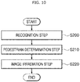
- the control method of the control system 1 of the autonomous vehicle may include a recognition step S200 of sensing the pedestrian M1 through the sensor unit 100.
- the presence or absence of the pedestrian M1 in front of the autonomous vehicle 90 may be determined by the camera unit 10 and the measurement unit 20, and one or more pieces of information of the camera unit 10, the measurement unit 20 and the sensor unit 100 may be transferred to the control unit 30.
- the control unit 30 may determine the type of the pedestrian M1 based on the information measured through the sensor unit 100 at a pedestrian determination step S210.
- the control unit 30 may classify the type of the pedestrian M1 into an adult, old man or child, through image analysis.
- an image suitable for the type of the pedestrian M1 may be irradiated onto the road L at an image irradiation step S220.
- contents may be displayed on the road surface. At this time, sound may be combined.
- a contents image C2 may be displayed in the form of a crosswalk on the surface of the road L, and an image of a person and arrow may be displayed on the image display unit 50.
- graphic such as a pictogram suitable for inducing a moving line of the child may be utilized rather than a character, and footprint-shaped sequential animation may be displayed as a contents image C3.
- the size of the displayed graphic contents may be raised by 50%, and the volume of the sound may be raised.
- the control method may help the autonomous vehicle 90 and the pedestrian M1 to recognize each other in a range from a long distance to a short distance, and thus guide the pedestrian M1 to cross the road L or stop the pedestrian M1 from crossing the road L, which makes it possible to secure the safety of the pedestrian M1.
- the autonomous vehicle 90 may approach a passenger and inform the passenger that the autonomous vehicle 90 is a vehicle to get in, using the side lighting of the autonomous vehicle 90.
- the autonomous vehicle 90 may open/close a door and induce the passenger to get in the vehicle, using a lighting pattern, which makes it possible to improve the convenience of the passenger.
- the control unit 30 may analyze a camera sensor image, determine the height and age of the pedestrian M1, and provide contents suitable for the pedestrian M1, thereby securing the safety of the pedestrian M1. Furthermore, the control unit 30 may analyze the image of the camera unit 10 and the sensor unit 100 during autonomous driving, specify the position, distance, height, age or walking speed of the pedestrian M1, and display contents suitable for the pedestrian M1, which makes it possible to secure the safety.
Landscapes
- Engineering & Computer Science (AREA)
- Mechanical Engineering (AREA)
- Automation & Control Theory (AREA)
- Transportation (AREA)
- Physics & Mathematics (AREA)
- General Physics & Mathematics (AREA)
- Multimedia (AREA)
- Human Computer Interaction (AREA)
- Mathematical Physics (AREA)
- Chemical & Material Sciences (AREA)
- Combustion & Propulsion (AREA)
- Theoretical Computer Science (AREA)
- Computer Vision & Pattern Recognition (AREA)
- Electromagnetism (AREA)
- Aviation & Aerospace Engineering (AREA)
- Radar, Positioning & Navigation (AREA)
- Remote Sensing (AREA)
- Lighting Device Outwards From Vehicle And Optical Signal (AREA)
- Control Of Driving Devices And Active Controlling Of Vehicle (AREA)
Description
- The present invention relates to a control method of an autonomous vehicle, and more particularly, to a control method of an autonomous vehicle, which can secure the safety of a pedestrian.
- In general, an autonomous vehicle refers to a vehicle that moves by itself even though a driver does not drive the vehicle.
- A variety of techniques are required for an autonomous vehicle to move by itself. In particular, advanced sensors capable of recognizing surrounding objects and a high-performance graphic processing device are installed in an autonomous vehicle. The advanced sensor measures a distance between objects, and senses danger to enable a driver to see all areas without a blind spot. The graphic processing device recognizes the surrounding environment of the vehicle through a plurality of cameras, and analyzes images to help the vehicle to stably operate. Furthermore, the graphic processing device may grasp the meanings of various safety signs, or monitor whether a vehicle in front suddenly stops or a person or animal suddenly runs into a road.
- Such an autonomous vehicle autonomously decides a traveling path by recognizing the surrounding environment through various sensors, and independently drives using its own power. Furthermore, a driver does not need to care about a road condition, and the autonomous vehicle avoids an obstacle by itself even though the obstacle suddenly appears, and autonomously drives to a destination while maintaining distances from vehicles at the front and rear thereof.
- However, there occurs an accident in which a pedestrian is hit and injured by an autonomous vehicle in operation. Furthermore, since a user may have difficulty in identifying an autonomous vehicle to get in, the user's convenience may be degraded. Therefore, there is a demand for a structure capable of solving the problem.
- A related art of the present invention is disclosed in Korean Patent Publication No.
2018-0115986 published on October 24, 2018 EP 3 216 653 A1 discloses in a first embodiment a control method of an autonomous vehicle comprising: a measurement step in which a measurement unit is operated to measure a position of a pedestrian and a distance between the pedestrian and a vehicle body. In a second embodimentEP 3 216 653 A1 discloses a measurement step in which a camera unit is operated to measure the pedestrian. In a third embodimentEP 3 216 653 A1 discloses an irradiation step with a degree-of-danger determination step in which it will be decided between the first degree of danger and a second degree of danger.DE 10 2013 217 057 A1 discloses an irradiation step in which an irradiation unit is operated to provide an image related to road crossing to the pedestrian. - An embodiment of the present invention is directed to a control method of an autonomous vehicle, which can secure the safety of a pedestrian.
- A control system of an autonomous vehicle may include: a camera unit installed on a vehicle body, and configured to take an image of a pedestrian; a measurement unit installed on the vehicle body, and configured to measure a position of the pedestrian and a distance to the pedestrian; a control unit configured to receive data of the camera unit and the measurement unit; and an image irradiation unit configured to operate according to a control signal of the control unit, and irradiate light to one or more of the pedestrian and a road.
- The measurement unit may include: a position measurement unit configured to measure the position of the pedestrian, and transfer the measured value to the control unit; and a distance measurement unit configured to measure a distance between the pedestrian and the vehicle body, and transfer the measured value to the control unit.
- The image irradiation unit may include: a first irradiation unit configured to irradiate light to the lower side of the pedestrian; and a second irradiation unit configured to irradiate an image onto the surface of the road.
- The control system may further include an image display unit installed at one or more of the front and side of the vehicle body, and configured to inform the pedestrian of information as an image.
- The control system may further include a side display unit installed at a side of the vehicle body, and configured to operate according to a control signal of the control unit and display a specific pattern of image to a target passenger.
- The control system may further include a scanning unit configured to scan the body of the target passenger and transfer the scan result to the control unit.
- The control system may further include a guide irradiation unit installed on the vehicle body, and configured to irradiate light in a lateral direction of the vehicle body in order to guide the target passenger to get in the vehicle.
- According to the invention a control method of an autonomous vehicle may include: a first measurement step in which a measurement unit is operated to measure a position of a pedestrian and a distance between the pedestrian and a vehicle body; a first irradiation step in which a first irradiation unit is operated to form a hot spot zone by irradiating light to the lower side of the pedestrian, when the distance between the pedestrian and the vehicle body is within a first range; a second measurement step in which a camera unit is operated to identify the pedestrian; a second irradiation step in which the first irradiation unit is operated to form the hot spot zone and a guide line at the lower side of the pedestrian, when the distance between the pedestrian and the vehicle body is within a second range; and a third irradiation step in which the first and second irradiation units are operated to provide an image related to road crossing to the pedestrian, when the distance between the pedestrian and the vehicle body is within a third distance.
- The lower limit of the first range may be larger than the upper limit of the second range, and the lower limit of the second range may be larger than the third distance.
- The second irradiation step may include forming the guide line by irradiating colorful light to the boundary of the road facing the pedestrian.
- The third irradiation step may include displaying a warning image to warn the pedestrian against crossing the road, when a control unit receiving the information of the measurement unit determines that the vehicle has precedence.
- The warning image may include one or more of an image displayed on the surface of the road and an image displayed on the front or side of the vehicle body.
- The third irradiation step may include irradiating a rectangular frame onto the road surface at a stop position and then irradiating an image onto the road facing the pedestrian to guide the pedestrian to cross the road, when the control unit receiving the information of the measurement unit determines that the pedestrian has precedence.
- Another control method of an autonomous vehicle may include: a moving step in which a vehicle body moves toward a target passenger; a pattern display step of displaying a specific pattern of image to the target passenger through a side display unit; a stop step in which the vehicle body stops in front of the target passenger; and an identification step in which a scanning unit scans the body of the target passenger, and a control unit identifies the target passenger based on information of the scanning unit.
- The identification step may include scanning one or more of the palm, face and iris of the target passenger, and determining whether the scan result coincides with information stored in a storage unit.
- The control method may further include automatically opening a door, when authentication for the target passenger is passed at the identification step.
- In accordance with the embodiments of the present invention, the control method may help the autonomous vehicle and the pedestrian to recognize each other in a range from a long distance to a short distance, and thus guide the pedestrian M1 to cross the road or stop the pedestrian from crossing the road, which makes it possible to secure the safety of the pedestrian.
- Furthermore, the autonomous vehicle may approach a passenger and inform the passenger that the autonomous vehicle is a vehicle to get in, using the side lighting of the autonomous vehicle. Furthermore, the autonomous vehicle may open/close a door and induce the passenger to get in the vehicle, using a lighting pattern, which makes it possible to improve the convenience of the passenger.
- Furthermore, when the pedestrian approaches the autonomous vehicle which is autonomously driving, the control unit may analyze a camera sensor image, determine the height and age of the pedestrian, and provide contents suitable for the pedestrian, thereby securing the safety of the pedestrian.
-
-
FIG. 1 illustrates a control system of an autonomous vehicle . -
FIG. 2 is a flowchart illustrating a control method of the control system of the autonomous vehicle in accordance with an embodiment of the present invention. -
FIG. 3 illustrates that the autonomous vehicle in accordance with the embodiment of the present invention senses a pedestrian and irradiates a hot spot zone. -
FIG. 4 illustrates that the autonomous vehicle in accordance with the embodiment of the present invention is moving. -
FIG. 5 illustrates that the autonomous vehicle in accordance with the embodiment of the present invention irradiates a hot spot zone and a guide line -
FIG. 6 illustrates that the autonomous vehicle in accordance with the embodiment of the present invention irradiates an image for preventing a pedestrian from crossing a road. -
FIG. 7 illustrates that the autonomous vehicle in accordance with the embodiment of the present invention irradiates a guide line onto a stop position. -
FIG. 8 illustrates that the autonomous vehicle in accordance with the embodiment of the present invention stops. -
FIG. 9 illustrates that the autonomous vehicle in accordance with the embodiment of the present invention irradiates an image for guiding a pedestrian to cross a road. -
FIG. 10 is a flowchart illustrating another control method of a control system of an autonomous vehicle. -
FIG. 11 illustrates that the autonomous vehicle is moving toward a target passenger. -
FIG. 12 illustrates that a specific pattern of image is displayed on the autonomous vehicle. -
FIG. 13 illustrates that a scanning unit takes an image of a hand of a target passenger. -
FIG. 14 is a flowchart illustrating still another control method of a control system of an autonomous vehicle. -
FIG. 15 illustrates that the autonomous vehicle approaches a pedestrian. -
FIG. 16 illustrates that the autonomous vehicle recognizes the height and age of a pedestrian. -
FIG. 17 illustrates that the autonomous vehicle irradiates an image suitable for a pedestrian onto a road surface. -
FIG. 18 illustrates that the autonomous vehicle irradiates an image suitable for an adult pedestrian onto a road surface. -
FIG. 19 illustrates that the autonomous vehicle irradiates an image suitable for a child pedestrian onto a road surface. -
FIG. 20 illustrates an image display unit of the autonomous vehicle. - Hereafter, a control system of an autonomous vehicle and a control method of an autonomous vehicle in accordance with an embodiment of the present invention will be described in detail with reference to the accompanying drawings. It should be noted that the drawings are not to precise scale and may be exaggerated in thickness of lines or sizes of components for descriptive convenience and clarity only.
- Furthermore, the terms as used herein are defined by taking functions of the invention into account and can be changed according to the custom or intention of users or operators. Therefore, definition of the terms should be made according to the overall disclosures set forth herein.
-
FIG. 1 illustrates a control system of an autonomous vehicle,FIG. 2 is a flowchart illustrating a control method of the control system of the autonomous vehicle in accordance with an embodiment of the present invention,FIG. 3 illustrates that the autonomous vehicle in accordance with the embodiment of the present invention senses a pedestrian and irradiates a hot spot zone,FIG. 4 illustrates that the autonomous vehicle in accordance with the embodiment of the present invention is moving,FIG. 5 illustrates that the autonomous vehicle in accordance with the embodiment of the present invention irradiates a hot spot zone and a guide line toward a pedestrian,FIG. 6 illustrates that the autonomous vehicle in accordance with the embodiment of the present invention irradiates a guide line for preventing a pedestrian from crossing a road,FIG. 7 illustrates that the autonomous vehicle in accordance with the embodiment of the present invention irradiates a guide line onto a stop position,FIG. 8 illustrates that the autonomous vehicle in accordance with the embodiment of the present invention stops, andFIG. 9 illustrates that the autonomous vehicle in accordance with the embodiment of the present invention irradiates an image for guiding a pedestrian to cross a road. - As illustrated in
FIGS. 1 to 9 , the control system 1 of the autonomous vehicle may include acamera unit 10, ameasurement unit 20, acontrol unit 30 and animage irradiation unit 40. Thecamera unit 10 may be installed on avehicle body 92 and take an image of a pedestrian M1. Themeasurement unit 20 may be installed on thevehicle body 92 and measure the position of the pedestrian M1 and a distance from the pedestrian M1. Thecontrol unit 30 may receive the data of thecamera unit 10 and themeasurement unit 20. Theimage irradiation unit 40 may operate according to a control signal of thecontrol unit 30, and irradiate light onto any one of the pedestrian M1 and a road L. The control system 1 of the autonomous vehicle in accordance with the embodiment of the present invention may further include animage display unit 50, aside display unit 60, ascanning unit 70, aguide irradiation unit 80 and asensor unit 100. - The plurality of
camera units 10 for taking images of the pedestrian M1 may be installed on thevehicle body 92 of theautonomous vehicle 90. The plurality ofcamera units 10 may be installed around thevehicle body 92, take images of the external conditions and the pedestrian M1, and transfer the taken images to thecontrol unit 30. Themeasurement unit 20 may be installed on thevehicle body 92, measure the position of the pedestrian M1 ahead of thevehicle body 92 and the distance from the pedestrian M1, and transfer the measured position and distance to thecontrol unit 30. Themeasurement unit 20 in accordance with an embodiment may include aposition measurement unit 22 and adistance measurement unit 24. - The
position measurement unit 22 may measure the position of the pedestrian M1, and transfer the measured value to thecontrol unit 30. Thedistance measurement unit 24 may measure the distance between the pedestrian M1 and thevehicle body 92, and transfer the measured value to thecontrol unit 30. One or more of a LiDAR (Light Detection and Ranging), radar and camera may be used as theposition measurement unit 22 and thedistance measurement unit 24. In addition, various measurement devices may be used as theposition measurement unit 22 and thedistance measurement unit 24. - The
control unit 30 may receive data of thecamera unit 10, themeasurement unit 20, thescanning unit 70 and thesensor unit 100, and control operations of theimage irradiation unit 40, theimage display unit 50, theside display unit 60 and theguide irradiation unit 80. - The
image irradiation unit 40 may operate according to a control signal of thecontrol unit 30, and various irradiation devices may be used as theimage irradiation unit 40, as long as they can irradiate light onto one or more of the pedestrian M1 and the road L. Theimage irradiation unit 40 in accordance with the embodiment of the present invention may include first andsecond irradiation units first irradiation unit 42 may irradiate light to the lower side of the pedestrian M1, and thesecond irradiation unit 44 may irradiate an image onto the surface of the road L. - The
first irradiation unit 42 may form a hot spot zone Z by irradiating light to the lower side of the pedestrian M1, such that the pedestrian M1 can be more reliably recognized. Even when there are a plurality of pedestrians M1, the plurality offirst irradiation units 42 may individually operate to form hot spot zones Z where light is concentrated on the lower sides of the respective pedestrians M1. Thefirst irradiation unit 42 may also irradiate a guide line G1 to form a red circle around the feet of thefirst irradiation unit 42. For this operation, thefirst irradiation unit 42 may use various light sources such as laser and lamp. - As the
second irradiation unit 44, various types of irradiation devices may be used as long as they can irradiate an image onto the surface of the road L. Thesecond irradiation unit 44 may be implemented with a panel or scanner for a micro display (MD) based on a projection scheme, such as a DMD (Digital Micromirror Device) or LCOS (Liquid Crystal On Silicon), or implemented with a panel using a direct projection scheme, such as an LCD (Liquid Crystal Display) or DMS (Digital MicroShutter Display). - The
image display unit 50 may be installed on one or more of the front and side surfaces of thevehicle body 92, and modified in various manners as long as theimage display unit 50 can inform the pedestrian M1 of information as an image. Theimage display unit 50 in accordance with an embodiment may be configured to display an image through an LED or liquid crystal screen, and installed in such a manner that contents can be identified even from a distance of about 30m. When a character is displayed through theimage display unit 50 serving as a display at the front of the vehicle, theimage display unit 50 may have a vertical length of 150mm or more. However, theimage display unit 50 is not limited thereto, but modified in various sizes. - The
side display unit 60 may be installed at the side surface of thevehicle body 92, and operated to display a specific pattern of image to a target passenger M2 according to a control signal of thecontrol unit 30. Thus, the target passenger M2 may easily recognize the vehicle to get in. Theside display unit 60 in accordance with an embodiment may be configured to output a specific pattern of image using a lighting, and modified in various manners. For example, a separate liquid crystal panel or optical fiber may be installed to output a specific pattern. - The
scanning unit 70 may scan the body of the target passenger M2, and transfer the scan result to thecontrol unit 30. Thescanning unit 70 may take an image of a part of the target passenger M2, such as the face, iris, fingerprint or palm, by which the target passenger M2 can be specified, and transfer the taken image to thecontrol unit 30. Thus, a door of theautonomous vehicle 90 can be opened without a separate smart key or the like. - The
guide irradiation unit 80 may be installed at a side surface and the like of thevehicle body 92, and irradiate light onto the ground surface at the lateral bottom of thevehicle body 92 in order to guide the target passenger M2 to get in the vehicle. Theguide irradiation unit 80 in accordance with an embodiment may irradiate belt-shaped light onto the road L facing the side surface of thevehicle body 92, in order to guide the target passenger M2 to get in the vehicle. - The
sensor unit 100 may be installed on thevehicle body 92, sense the pedestrian M1, take an image of the pedestrian M1, and transfer the sensing result and the taken image to thecontrol unit 30. Thesensor unit 100 may include one or more of a camera, laser and LiDAR. Thesensor unit 100 may measure the height and position of the pedestrian M1, take an image of the pedestrian M1, and transfer the measured values and the taken image to thecontrol unit 30, and thecontrol unit 30 may determine the type of the pedestrian M1 based on the information measured through thesensor unit 100. Specifically, thecontrol unit 30 may determine whether the pedestrian M1 is an adult, child or old man. - As illustrated in
FIGS. 2 and3 , the control method of the control system 1 of the autonomous vehicle in accordance with the embodiment of the present invention may include a first measurement step S10 in which themeasurement unit 20 is operated to measure the position of the pedestrian M1 and a distance from the pedestrian M1. - The
position measurement unit 22 installed in the control system 1 of the autonomous vehicle may be operated to measure the position of the pedestrian M1, and thedistance measurement unit 24 may be operated to measure a distance between the pedestrian M1 and thevehicle body 92. Through the operation of themeasurement unit 20, a target at a long distance can be recognized. - When the distance between the pedestrian M1 and the
vehicle body 92 is within a first range L1, thefirst irradiation unit 42 may be operated to irradiate light to the lower side of the pedestrian M1, thereby forming a hot spot zone Z, at a first irradiation step S20. - When the distance between the pedestrian M1 and the
vehicle body 92 is within the first range L1, theimage irradiation unit 40 may be operated to irradiate light to the pedestrian M1 or around the pedestrian M1, thereby forming the hot spot zone Z. Thus, the pedestrian M1 can be easily recognized. - As illustrated in
FIGS. 1 ,2 and4 , thecamera unit 10 may be operated to identify the pedestrian M1 at a second measurement step S30. The measured value of thecamera unit 10 may be transferred to thecontrol unit 30, and thecontrol unit 30 may determine whether an object recognized as the pedestrian M1 through image recognition is a person. At this time, since the light irradiated from theimage irradiation unit 40 is irradiated to the pedestrian M1, thecamera unit 10 may recognize the object more clearly. When lighting is sufficiently secured as in the daytime, rays capable of specifying an object may be irradiated to the pedestrian M1. Thus, thecamera unit 10 can recognize the object more clearly. - As illustrated in
FIGS. 1 ,2 and5 , when the distance between the pedestrian M1 and thevehicle body 92 is within a second range L2, thefirst irradiation unit 42 may be operated to form a hot spot zone Z and a guide line G2 at the lower side of the pedestrian M1 at a second irradiation step S40. At the second irradiation step S40, thefirst irradiation unit 42 may form the guide line G2 by irradiating colorful light to the boundary between the pedestrian M1 and the road L facing the pedestrian M1. - Since the red guide line G2 is extended along the boundary between the sidewalk and the road L facing the pedestrian M1, the red guide line G2 may warn the pedestrian M1 against crossing the road L without permission.
- As illustrated in
FIGS. 1 ,2 and6 , when the distance between the pedestrian M1 and thevehicle body 92 becomes shorter than a third distance L3, the first andsecond irradiation units - When the
control unit 30 receiving the information of themeasurement unit 20 determines that the vehicle has precedence over the pedestrian M1 at the third irradiation step, the first andsecond irradiation units control unit 30 may determine which of the vehicle and the pedestrian has precedence, through various methods. For example, thecontrol unit 30 may receive a signal of a signal device installed on the road and determine which of the vehicle and the pedestrian has precedence. Alternatively, thecontrol unit 30 may determine which of the vehicle and the pedestrian has precedence, based on a traffic signal taken through thecamera unit 10. - The warning image may be displayed on the surface of the road L or displayed on the front or side surface of the
vehicle body 92. The contents image C1 in accordance with an embodiment may be mainly displayed on the road L, but modified in various manners. For example, the contents image C1 may be displayed on the road L and the outside of thevehicle body 92 at the same time. When the vehicle has precedence, a specific pictogram or text may be displayed to warn the pedestrian M1 against crossing the road L. At this time, sound may also be outputted. - As illustrated in
FIGS. 1 ,2 and7 , when thecontrol unit 30 receiving the information of themeasurement unit 20 determines that the pedestrian M1 has precedence at the third irradiation step, the vehicle may irradiate a guide line G3 having a rectangular frame shape onto the road surface at a stop position, and then stop ahead of the pedestrian M1 as illustrated inFIG. 8 . As illustrated inFIG. 9 , the vehicle may irradiate a contents image C2 onto the road L facing the pedestrian M1, the contents image C2 guiding the pedestrian M1 to cross the road L. - That is, when the pedestrian M1 has precedence in the case that the
vehicle body 92 reaches a position at a third distance L3 from the pedestrian M1, theimage irradiation unit 40 may irradiate the rectangular frame-shaped guide line G3 at a stop position of theautonomous vehicle 90. - Then, the vehicle may stop after displaying one or more of a pictogram, text and sound on the road L1 facing the pedestrian M1.
- The second range L2 may be larger than the third distance L3, and the first range L1 may be larger than the second range L2. That is, the lower limit of the second range L2 may be larger than the third distance L3, and the lower limit of the first range L1 may be larger than the upper limit of the second range L2. In an embodiment, the intermediate value of the first range L1 may be set to 150m, the intermediate value of the second range L2 may be set to 100m, and the third distance L3 may be set to 50m. However, the present invention is not limited thereto, but the values may be varied depending on conditions.
- Hereafter, another control method of a control system 1 of an autonomous vehicle will be described with reference to the drawings.
- For convenience of description, components which are configured and operated in the same manner as those of the above-described embodiment may be represented by like reference numerals, and the detailed descriptions thereof will omitted herein.
-
FIG. 10 is a flowchart illustrating another control method of a control system of an autonomous vehicle,FIG. 11 illustrates that the autonomous vehicle,FIG. 12 illustrates that a specific pattern of image is displayed on the autonomous vehicle , andFIG. 13 illustrates that a scanning unit takes an image of a hand of a target passenger. - As illustrated in
FIGS. 10 to 13 , theautonomous vehicle 90 may move toward a target passenger M2 and inform the target passenger M2 that theautonomous vehicle 90 is a vehicle to get in, through a lighting of theside display unit 60 of the vehicle. Furthermore, theautonomous vehicle 90 may open/close a door and induce the target passenger M2 to get in the vehicle, through a lighting pattern, which makes it possible to improve the convenience of the passenger. - The control method of the control system 1 of the autonomous vehicle may include a moving step S100 in which the
vehicle body 92 moves toward the target passenger M2. The target passenger M2 may send a signal to theautonomous vehicle 90 using a smart phone or smart watch, and call theautonomous vehicle 90 through other various methods. Then, theautonomous vehicle 90 may move toward the target passenger M2. - As illustrated in
FIG. 12 , the vehicle may display a specific pattern of image to the target passenger M2 through theside display unit 60 at a pattern display step S110. Since an individualized pattern lighting is displayed on the exterior of the vehicle, the target passenger M2 may recognize that theautonomous vehicle 90 is a vehicle which the target passenger M2 will get in. - The
vehicle body 92 of theautonomous vehicle 90 may stop in front of the target passenger M2 at a stop step S120. - Then, the
control unit 30 may scan the body of the target passenger M2 through thescanning unit 70, and then identify the target passenger M2 based on the information of thescanning unit 70, at an identification step S130. At the identification step, thecontrol unit 30 may scan one or more of the palm, face and iris of the target passenger M2, and determine whether the scanned information coincides with information stored in a storage unit. Alternatively, as illustrated inFIG. 13 , the target passenger M2 may add a hand gesture to a pattern displayed on theside display unit 60 after the vehicle stops, in order to specify the target passenger M2. Alternatively, thecontrol unit 30 may recognize the face of the target passenger M2 through thescanning unit 70 installed in the control system 1 of the autonomous vehicle, in order to specify the target passenger M2. - When the authentication for the target passenger M2 passes at the identification step, a door may be automatically opened at an opening step S140. Although the lighting of the
side display unit 60 installed at the side surface of thevehicle body 92 is mainly operated, theguide irradiation unit 80 may be operated to irradiate guide light onto the road surface at the door, and guide the target passenger M2 to get in the vehicle. - Hereafter, still another control method of a control system 1 of an autonomous vehicle will be described with reference to the drawings.
- For convenience of description, components which are configured and operated in the same manner as those of the above-described embodiment may be represented by like reference numerals, and the detailed descriptions thereof are omitted herein.
-
FIG. 14 is still another flowchart illustrating a control method of a control system of an autonomous vehicle,FIG. 15 illustrates that the autonomous vehicle approaches a pedestrian,FIG. 16 illustrates that the autonomous vehicle recognizes the height and age of a pedestrian,FIG. 17 illustrates that the autonomous vehicle irradiates an image suitable for a pedestrian onto a road surface,FIG. 18 illustrates that the autonomous vehicle irradiates an image suitable for an adult pedestrian onto a road surface,FIG. 19 illustrates that the autonomous vehicle irradiates an image suitable for a child pedestrian onto a road surface, andFIG. 20 illustrates an image display unit of the autonomous vehicle. - As illustrated in
FIGS. 14 to 20 , the control method of the control system 1 of the autonomous vehicle may analyze images of thecamera unit 10 and thesensor unit 100 when a pedestrian M1 approaches the vehicle which is autonomously driving, and provide contents suitable for the pedestrian M1, thereby preventing a safety accident. - As illustrated in
FIGS. 15 and16 , the control method of the control system 1 of the autonomous vehicle may include a recognition step S200 of sensing the pedestrian M1 through thesensor unit 100. The presence or absence of the pedestrian M1 in front of theautonomous vehicle 90 may be determined by thecamera unit 10 and themeasurement unit 20, and one or more pieces of information of thecamera unit 10, themeasurement unit 20 and thesensor unit 100 may be transferred to thecontrol unit 30. - The
control unit 30 may determine the type of the pedestrian M1 based on the information measured through thesensor unit 100 at a pedestrian determination step S210. Thecontrol unit 30 may classify the type of the pedestrian M1 into an adult, old man or child, through image analysis. - As illustrated in
FIG. 17 , an image suitable for the type of the pedestrian M1 may be irradiated onto the road L at an image irradiation step S220. Through theimage display unit 50 and theimage irradiation unit 40 which are installed at the front of theautonomous vehicle 90, contents may be displayed on the road surface. At this time, sound may be combined. - As illustrated in
FIG. 18 , when the pedestrian M1 is an adult, a contents image C2 may be displayed in the form of a crosswalk on the surface of the road L, and an image of a person and arrow may be displayed on theimage display unit 50. - When the pedestrian M1 is a child as illustrated in
FIG. 19 , graphic such as a pictogram suitable for inducing a moving line of the child may be utilized rather than a character, and footprint-shaped sequential animation may be displayed as a contents image C3. - When the pedestrian M1 is an old man, the size of the displayed graphic contents may be raised by 50%, and the volume of the sound may be raised.
- In accordance with the embodiment of the present invention, the control method may help the
autonomous vehicle 90 and the pedestrian M1 to recognize each other in a range from a long distance to a short distance, and thus guide the pedestrian M1 to cross the road L or stop the pedestrian M1 from crossing the road L, which makes it possible to secure the safety of the pedestrian M1. Furthermore, theautonomous vehicle 90 may approach a passenger and inform the passenger that theautonomous vehicle 90 is a vehicle to get in, using the side lighting of theautonomous vehicle 90. Furthermore, theautonomous vehicle 90 may open/close a door and induce the passenger to get in the vehicle, using a lighting pattern, which makes it possible to improve the convenience of the passenger. Furthermore, when the pedestrian M1 approaches the autonomous vehicle which is autonomously driving, thecontrol unit 30 may analyze a camera sensor image, determine the height and age of the pedestrian M1, and provide contents suitable for the pedestrian M1, thereby securing the safety of the pedestrian M1. Furthermore, thecontrol unit 30 may analyze the image of thecamera unit 10 and thesensor unit 100 during autonomous driving, specify the position, distance, height, age or walking speed of the pedestrian M1, and display contents suitable for the pedestrian M1, which makes it possible to secure the safety. - Although a preferred embodiment of the invention has been disclosed for illustrative purposes, those skilled in the art will appreciate that various modifications, additions and substitutions are possible, without departing from the scope of the invention as defined in the accompanying claims.
Claims (6)
- A control method of an autonomous vehicle, comprising:a first measurement step (S10) in which a measurement unit (20) is operated to measure a position of a pedestrian (M1) and a distance between the pedestrian (M1) and a vehicle body (92);a first irradiation step (S20) in which a first irradiation unit (42) is operated to form a hot spot zone (Z) by irradiating light to the lower side of the pedestrian (M1), when the distance between the pedestrian (M1) and the vehicle body (92) is within a first range (L1);a second measurement step (S30) in which a camera unit (10) is operated to identify the pedestrian (M1);a second irradiation step (S40) in which the first irradiation unit (42) is operated to form the hot spot zone (Z) and a guide line (G2) at the lower side of the pedestrian (M1), when the distance between the pedestrian (M1) and the vehicle body (92) is within a second range (L2); anda third irradiation step (S50) in which the first irradiation unit (42) and a second irradiation unit (44) configured to irradiate an image onto the surface of the road are operated to provide an image (C1, C2) related to road crossing to the pedestrian (M1), when the distance between the pedestrian (M1) and the vehicle body (92) is shorter than a third distance (L3).
- The control method of claim 1, wherein the lower limit of the first range (L1) is larger than the upper limit of the second range (L2), and the lower limit of the second range (L2) is larger than the third distance (L3).
- The control method of claim 1, wherein the second irradiation step (S40) comprises forming the guide line (G2) by irradiating colorful light to the boundary of the road facing the pedestrian.
- The control method of claim 1, wherein the third irradiation step (S50) comprises displaying a warning image (C1) to warn the pedestrian (M1) against crossing the road (L), when a control unit (30) receiving the information of the measurement unit 20) determines that the vehicle has precedence.
- The control method of claim 4, wherein the warning image (C1) comprises one or more of an image displayed on the surface of the road (L) and an image displayed on the front or side of the vehicle body (92).
- The control method of claim 1, wherein the third irradiation step (S50) comprises irradiating a rectangular frame onto the road surface at a stop position and then irradiating an image (C2) onto the road facing the pedestrian (M1) to guide the pedestrian (M1) to cross the road (L), when the control unit (30) receiving the information of the measurement unit (20) determines that the pedestrian (M1) has precedence.
Applications Claiming Priority (1)
| Application Number | Priority Date | Filing Date | Title |
|---|---|---|---|
| KR1020180141618A KR102619558B1 (en) | 2018-11-16 | 2018-11-16 | Control system of autonomous vehicle and control method thereof |
Publications (2)
| Publication Number | Publication Date |
|---|---|
| EP3653440A1 EP3653440A1 (en) | 2020-05-20 |
| EP3653440B1 true EP3653440B1 (en) | 2021-05-26 |
Family
ID=65011805
Family Applications (1)
| Application Number | Title | Priority Date | Filing Date |
|---|---|---|---|
| EP18248167.1A Active EP3653440B1 (en) | 2018-11-16 | 2018-12-28 | Control method of an autonomous vehicle |
Country Status (3)
| Country | Link |
|---|---|
| US (3) | US10843622B2 (en) |
| EP (1) | EP3653440B1 (en) |
| KR (1) | KR102619558B1 (en) |
Families Citing this family (27)
| Publication number | Priority date | Publication date | Assignee | Title |
|---|---|---|---|---|
| US9606539B1 (en) | 2015-11-04 | 2017-03-28 | Zoox, Inc. | Autonomous vehicle fleet service and system |
| US11283877B2 (en) * | 2015-11-04 | 2022-03-22 | Zoox, Inc. | Software application and logic to modify configuration of an autonomous vehicle |
| WO2017079341A2 (en) | 2015-11-04 | 2017-05-11 | Zoox, Inc. | Automated extraction of semantic information to enhance incremental mapping modifications for robotic vehicles |
| MX2019014872A (en) * | 2017-06-20 | 2020-02-07 | Nissan Motor | Travel control method and travel control device. |
| KR102619558B1 (en) | 2018-11-16 | 2024-01-02 | 현대모비스 주식회사 | Control system of autonomous vehicle and control method thereof |
| US11899448B2 (en) * | 2019-02-21 | 2024-02-13 | GM Global Technology Operations LLC | Autonomous vehicle that is configured to identify a travel characteristic based upon a gesture |
| US11016492B2 (en) * | 2019-02-28 | 2021-05-25 | Zoox, Inc. | Determining occupancy of occluded regions |
| US11221627B2 (en) * | 2019-03-08 | 2022-01-11 | Pony Ai Inc. | Directed interaction of customers with autonomous vehicles |
| KR102449306B1 (en) * | 2019-06-19 | 2022-09-29 | 미쓰비시덴키 가부시키가이샤 | Pairing indication device, pairing indication system and pairing indication method |
| JP7226167B2 (en) * | 2019-07-23 | 2023-02-21 | トヨタ自動車株式会社 | vehicle |
| JP7167880B2 (en) * | 2019-08-27 | 2022-11-09 | トヨタ自動車株式会社 | Stop line position estimation device and vehicle control system |
| JP7335760B2 (en) * | 2019-09-17 | 2023-08-30 | 株式会社Subaru | Notification device and notification method for automatic driving vehicle |
| US10816993B1 (en) * | 2019-11-23 | 2020-10-27 | Ha Q Tran | Smart vehicle |
| US11351961B2 (en) * | 2020-01-29 | 2022-06-07 | Ford Global Technologies, Llc | Proximity-based vehicle security systems and methods |
| WO2021166814A1 (en) * | 2020-02-17 | 2021-08-26 | 株式会社小糸製作所 | Lamp system |
| KR20210136567A (en) * | 2020-05-08 | 2021-11-17 | 현대자동차주식회사 | Communication lighting system of vehicle |
| US11682272B2 (en) * | 2020-07-07 | 2023-06-20 | Nvidia Corporation | Systems and methods for pedestrian crossing risk assessment and directional warning |
| US12054177B2 (en) * | 2020-07-23 | 2024-08-06 | Autobrains Technologies Ltd | Child forward collision warning |
| US11738682B2 (en) * | 2020-10-08 | 2023-08-29 | Motional Ad Llc | Communicating vehicle information to pedestrians |
| KR102568270B1 (en) * | 2021-01-11 | 2023-08-21 | 한양대학교 에리카산학협력단 | Pedestrian communication system for self driving cars |
| KR102568288B1 (en) * | 2021-02-09 | 2023-08-18 | 한양대학교 에리카산학협력단 | Traffic safety system by communication with self driving cars |
| JP2023115856A (en) * | 2022-02-08 | 2023-08-21 | 本田技研工業株式会社 | Vehicular headlight device |
| JP2023115852A (en) | 2022-02-08 | 2023-08-21 | 本田技研工業株式会社 | Vehicular headlight device |
| KR20230156609A (en) * | 2022-05-06 | 2023-11-14 | 비플랫 유한회사 | Authentication System Using Light Emitting Unit of Transport Means and Authentication Information Processing Method by It |
| US12054286B2 (en) * | 2022-10-28 | 2024-08-06 | Supernal, Llc | Methods and systems for lighting a vertical take-off and landing vehicle |
| CN116653979B (en) * | 2023-05-31 | 2024-01-05 | 钧捷智能(深圳)有限公司 | Driver visual field range ray tracing method and DMS system |
| KR102677983B1 (en) * | 2023-09-05 | 2024-06-25 | (주)오토노머스에이투지 | Method for determining failure of a projector installed on autonomous vehicle and projector fault determining device using the same |
Family Cites Families (72)
| Publication number | Priority date | Publication date | Assignee | Title |
|---|---|---|---|---|
| JP4720650B2 (en) | 2006-06-30 | 2011-07-13 | アイシン・エィ・ダブリュ株式会社 | Road surface projection apparatus and road surface projection method |
| JP5262057B2 (en) * | 2006-11-17 | 2013-08-14 | 株式会社豊田中央研究所 | Irradiation device |
| US8384531B2 (en) * | 2009-04-02 | 2013-02-26 | GM Global Technology Operations LLC | Recommended following distance on full-windshield head-up display |
| US8260482B1 (en) * | 2010-04-28 | 2012-09-04 | Google Inc. | User interface for displaying internal state of autonomous driving system |
| US20110285519A1 (en) * | 2010-05-21 | 2011-11-24 | Kurt Scheuermann | Static Officer Proximity Alert System |
| JP2012236244A (en) * | 2011-05-10 | 2012-12-06 | Sony Corp | Robot device, method of controlling the same, and program for controlling the same |
| DE102011081382A1 (en) * | 2011-08-23 | 2013-02-28 | Robert Bosch Gmbh | Method and device for changing a light emission of at least one headlight of a vehicle |
| US8801245B2 (en) * | 2011-11-14 | 2014-08-12 | Magna Mirrors Of America, Inc. | Illumination module for vehicle |
| JP5696701B2 (en) * | 2012-08-31 | 2015-04-08 | 株式会社デンソー | Anti-pedestrian notification device |
| US9196164B1 (en) * | 2012-09-27 | 2015-11-24 | Google Inc. | Pedestrian notifications |
| US8676431B1 (en) * | 2013-03-12 | 2014-03-18 | Google Inc. | User interface for displaying object-based indications in an autonomous driving system |
| US9481287B2 (en) * | 2014-01-21 | 2016-11-01 | Harman International Industries, Inc. | Roadway projection system |
| US9567102B1 (en) * | 2014-01-29 | 2017-02-14 | Stan W. Ross | Safety system with projectable warning indicia |
| US9475422B2 (en) * | 2014-05-22 | 2016-10-25 | Applied Invention, Llc | Communication between autonomous vehicle and external observers |
| JP6075331B2 (en) * | 2014-06-13 | 2017-02-08 | トヨタ自動車株式会社 | Vehicle lighting device |
| JP6112072B2 (en) * | 2014-06-19 | 2017-04-12 | トヨタ自動車株式会社 | Vehicle lighting device |
| US9823081B2 (en) | 2014-12-03 | 2017-11-21 | Ford Global Technologies, Llc | Vehicle passenger identification |
| US9855890B2 (en) * | 2014-12-11 | 2018-01-02 | Toyota Motor Engineering & Manufacturing North America, Inc. | Autonomous vehicle interaction with external environment |
| FR3034078B1 (en) * | 2015-03-27 | 2017-03-24 | Airbus Helicopters | METHOD AND DEVICE FOR SIGNALING TO THE GROUND AN AIRCRAFT IN FLIGHT AND AN AIRCRAFT PROVIDED WITH SAID DEVICE |
| CN113147579B (en) * | 2015-04-10 | 2024-05-21 | 麦克赛尔株式会社 | System mounted on vehicle |
| US10112528B1 (en) * | 2015-07-28 | 2018-10-30 | Apple Inc. | Exterior lighting and warning system |
| FR3041110B1 (en) * | 2015-09-14 | 2018-03-16 | Valeo Vision | PROJECTION METHOD FOR A MOTOR VEHICLE OF AN IMAGE ON A PROJECTION SURFACE |
| US9849784B1 (en) * | 2015-09-30 | 2017-12-26 | Waymo Llc | Occupant facing vehicle display |
| US9494940B1 (en) * | 2015-11-04 | 2016-11-15 | Zoox, Inc. | Quadrant configuration of robotic vehicles |
| KR20170058188A (en) * | 2015-11-18 | 2017-05-26 | 엘지전자 주식회사 | Driver Assistance Apparatus and Vehicle Having The Same |
| DE102015225411A1 (en) * | 2015-12-16 | 2017-06-22 | Bayerische Motoren Werke Aktiengesellschaft | Communication between road users |
| US10134280B1 (en) * | 2016-02-23 | 2018-11-20 | Taehyun You | Vehicular notifications |
| US9858821B2 (en) | 2016-02-26 | 2018-01-02 | Ford Global Technologies, Llc | Autonomous vehicle passenger locator |
| US10088846B2 (en) | 2016-03-03 | 2018-10-02 | GM Global Technology Operations LLC | System and method for intended passenger detection |
| CN107176161B (en) | 2016-03-10 | 2021-11-23 | 松下电器(美国)知识产权公司 | Recognition result presentation device, recognition result presentation method, and autonomous moving object |
| JP6447545B2 (en) * | 2016-03-11 | 2019-01-09 | トヨタ自動車株式会社 | Vehicle lighting device |
| CN107346386A (en) * | 2016-05-05 | 2017-11-14 | 阿里巴巴集团控股有限公司 | A kind of certification, information generating method and device for certification |
| US9845043B1 (en) * | 2016-06-15 | 2017-12-19 | Denso International America, Inc. | Projected laser lines/graphics to visually indicate truck turning path |
| US20180012197A1 (en) * | 2016-07-07 | 2018-01-11 | NextEv USA, Inc. | Battery exchange licensing program based on state of charge of battery pack |
| US11599833B2 (en) * | 2016-08-03 | 2023-03-07 | Ford Global Technologies, Llc | Vehicle ride sharing system and method using smart modules |
| US10471904B2 (en) * | 2016-08-08 | 2019-11-12 | Toyota Motor Engineering & Manufacturing North America, Inc. | Systems and methods for adjusting the position of sensors of an automated vehicle |
| CN115204577A (en) * | 2016-08-18 | 2022-10-18 | 动态Ad有限责任公司 | System, method and storage medium for summoning a vehicle |
| US10095229B2 (en) * | 2016-09-13 | 2018-10-09 | Ford Global Technologies, Llc | Passenger tracking systems and methods |
| US10202115B2 (en) * | 2016-09-13 | 2019-02-12 | Here Global B.V. | Method and apparatus for triggering vehicle sensors based on human accessory detection |
| US20180075565A1 (en) * | 2016-09-13 | 2018-03-15 | Ford Global Technologies, Llc | Passenger validation systems and methods |
| CN107839797A (en) * | 2016-09-20 | 2018-03-27 | 福特环球技术公司 | Bicycle safe forbidden zone system |
| KR102561132B1 (en) * | 2016-09-21 | 2023-07-28 | 엘지전자 주식회사 | Vehicle control device mounted on vehicle and method for controlling the vehicle |
| US10210760B2 (en) * | 2016-09-21 | 2019-02-19 | Dura Operating, Llc | System and method for autonomous parking of a vehicle |
| FR3056775B1 (en) * | 2016-09-29 | 2021-08-20 | Valeo Vision | PROCESS FOR PROJECTING IMAGES BY A PROJECTION SYSTEM OF A MOTOR VEHICLE, AND ASSOCIATED PROJECTION SYSTEM |
| KR102003940B1 (en) * | 2016-11-11 | 2019-10-01 | 엘지전자 주식회사 | Autonomous vehicle and control method thereof |
| US10196058B2 (en) * | 2016-11-28 | 2019-02-05 | drive.ai Inc. | Method for influencing entities at a roadway intersection |
| KR102648812B1 (en) * | 2016-12-15 | 2024-03-19 | 현대자동차주식회사 | A vehicle and method for notifying pedesrian sensing |
| US10261513B2 (en) * | 2016-12-19 | 2019-04-16 | drive.ai Inc. | Methods for communicating state, intent, and context of an autonomous vehicle |
| JP6465317B2 (en) * | 2017-03-10 | 2019-02-06 | 株式会社Subaru | Image display device |
| JP6465318B2 (en) * | 2017-03-10 | 2019-02-06 | 株式会社Subaru | Image display device |
| JP6593803B2 (en) * | 2017-03-10 | 2019-10-23 | 株式会社Subaru | Image display device |
| JP6497818B2 (en) * | 2017-03-10 | 2019-04-10 | 株式会社Subaru | Image display device |
| JP6515125B2 (en) * | 2017-03-10 | 2019-05-15 | 株式会社Subaru | Image display device |
| US10254762B2 (en) * | 2017-03-29 | 2019-04-09 | Luminar Technologies, Inc. | Compensating for the vibration of the vehicle |
| US9904375B1 (en) * | 2017-04-10 | 2018-02-27 | Uber Technologies, Inc. | LIDAR display systems and methods |
| KR101908308B1 (en) * | 2017-04-12 | 2018-10-16 | 엘지전자 주식회사 | Lamp for Vehicle |
| KR102287316B1 (en) | 2017-04-14 | 2021-08-09 | 현대자동차주식회사 | Apparatus and method for autonomous driving control, vehicle system |
| JP2019010962A (en) * | 2017-06-30 | 2019-01-24 | マツダ株式会社 | Vehicle headlight and light distribution control device of vehicle headlight |
| US10220769B1 (en) * | 2017-08-22 | 2019-03-05 | Ford Global Technologies, Llc | Vehicular image projection |
| US10796580B2 (en) * | 2017-08-22 | 2020-10-06 | Ford Global Technologies, Llc | Vehicular image projection |
| US20190066510A1 (en) * | 2017-08-22 | 2019-02-28 | Ford Global Technologies, Llc | Vehicular image projection |
| US10401858B2 (en) | 2017-08-29 | 2019-09-03 | Waymo Llc | Arranging passenger pickups for autonomous vehicles |
| US10343593B2 (en) * | 2017-10-10 | 2019-07-09 | Gm Global Technology Operations Llc. | Real-time analysis and augmented pathway projection for vehicle passengers |
| US20190113919A1 (en) * | 2017-10-18 | 2019-04-18 | Luminar Technologies, Inc. | Controlling an autonomous vehicle using smart control architecture selection |
| US10768304B2 (en) * | 2017-12-13 | 2020-09-08 | Luminar Technologies, Inc. | Processing point clouds of vehicle sensors having variable scan line distributions using interpolation functions |
| US10755115B2 (en) * | 2017-12-29 | 2020-08-25 | Here Global B.V. | Method, apparatus, and system for generating synthetic image data for machine learning |
| US20190220677A1 (en) * | 2018-01-17 | 2019-07-18 | GM Global Technology Operations LLC | Structured light illumination system for object detection |
| JP2019153106A (en) * | 2018-03-05 | 2019-09-12 | 矢崎総業株式会社 | On-vehicle system and boarding/alighting authentication system |
| JP2018152134A (en) * | 2018-06-25 | 2018-09-27 | 株式会社ニコン | Autonomous travel vehicle |
| JP7295863B2 (en) * | 2018-08-06 | 2023-06-21 | 株式会社小糸製作所 | Vehicle display system and vehicle |
| US10857938B2 (en) | 2018-08-27 | 2020-12-08 | GM Global Technology Operations LLC | Autonomous vehicle identification |
| KR102619558B1 (en) | 2018-11-16 | 2024-01-02 | 현대모비스 주식회사 | Control system of autonomous vehicle and control method thereof |
-
2018
- 2018-11-16 KR KR1020180141618A patent/KR102619558B1/en active IP Right Grant
- 2018-12-28 US US16/235,686 patent/US10843622B2/en active Active
- 2018-12-28 EP EP18248167.1A patent/EP3653440B1/en active Active
-
2019
- 2019-12-06 US US16/705,946 patent/US10981497B2/en active Active
-
2020
- 2020-03-16 US US16/820,397 patent/US20200215966A1/en not_active Abandoned
Also Published As
| Publication number | Publication date |
|---|---|
| US20200156533A1 (en) | 2020-05-21 |
| KR20200064182A (en) | 2020-06-08 |
| US20200156535A1 (en) | 2020-05-21 |
| US20200215966A1 (en) | 2020-07-09 |
| US10843622B2 (en) | 2020-11-24 |
| KR102619558B1 (en) | 2024-01-02 |
| US10981497B2 (en) | 2021-04-20 |
| EP3653440A1 (en) | 2020-05-20 |
Similar Documents
| Publication | Publication Date | Title |
|---|---|---|
| EP3653440B1 (en) | Control method of an autonomous vehicle | |
| CN108569207B (en) | Image display device | |
| CN108569203B (en) | Image display device | |
| KR101908308B1 (en) | Lamp for Vehicle | |
| CN107176095B (en) | Recognition result presentation device and method, and recognition object presentation device and method | |
| JP4525915B2 (en) | Driving assistance device | |
| CN108569204B (en) | Image display device | |
| JP5341402B2 (en) | In-vehicle display system | |
| KR101768500B1 (en) | Drive assistance apparatus and method for controlling the same | |
| KR102020340B1 (en) | A intersection and walking safety monitoring system using lidar | |
| EP3653471B1 (en) | Projection apparatus for use with movable body, portable device, and program | |
| CN108290519A (en) | Control unit and method for dividing moving region | |
| KR20140084962A (en) | System and method for traveling self-control expressway | |
| CN110733496A (en) | Information processing apparatus, information processing method, and recording medium | |
| KR101739519B1 (en) | Hud information displaying control device for optimazation location | |
| KR20200058613A (en) | Apparatus and method for controlling Autonomous vehicle using control system in intersection | |
| RU2642017C2 (en) | Vehicle imaging system, vehicle imaging method and device | |
| JP2002157697A (en) | Controller for vehicle | |
| KR102144772B1 (en) | Reversible lane operating system | |
| KR102484296B1 (en) | Convex mirror with vehicle detection and alarm at intersections | |
| JP3200402B2 (en) | Platform safety monitoring device | |
| US20200285044A1 (en) | Display device, display control method, and storage medium | |
| JP2016020125A (en) | Automatic driving mechanism | |
| CN112130551A (en) | Decision planning method and device for travel path and speed of unmanned vehicle | |
| CN109466557B (en) | Vehicle control device, vehicle control method, and storage medium |
Legal Events
| Date | Code | Title | Description |
|---|---|---|---|
| PUAI | Public reference made under article 153(3) epc to a published international application that has entered the european phase |
Free format text: ORIGINAL CODE: 0009012 |
|
| STAA | Information on the status of an ep patent application or granted ep patent |
Free format text: STATUS: REQUEST FOR EXAMINATION WAS MADE |
|
| 17P | Request for examination filed |
Effective date: 20181228 |
|
| AK | Designated contracting states |
Kind code of ref document: A1 Designated state(s): AL AT BE BG CH CY CZ DE DK EE ES FI FR GB GR HR HU IE IS IT LI LT LU LV MC MK MT NL NO PL PT RO RS SE SI SK SM TR |
|
| AX | Request for extension of the european patent |
Extension state: BA ME |
|
| RBV | Designated contracting states (corrected) |
Designated state(s): AL AT BE BG CH CY CZ DE DK EE ES FI FR GB GR HR HU IE IS IT LI LT LU LV MC MK MT NL NO PL PT RO RS SE SI SK SM TR |
|
| GRAP | Despatch of communication of intention to grant a patent |
Free format text: ORIGINAL CODE: EPIDOSNIGR1 |
|
| STAA | Information on the status of an ep patent application or granted ep patent |
Free format text: STATUS: GRANT OF PATENT IS INTENDED |
|
| INTG | Intention to grant announced |
Effective date: 20210209 |
|
| GRAS | Grant fee paid |
Free format text: ORIGINAL CODE: EPIDOSNIGR3 |
|
| GRAA | (expected) grant |
Free format text: ORIGINAL CODE: 0009210 |
|
| STAA | Information on the status of an ep patent application or granted ep patent |
Free format text: STATUS: THE PATENT HAS BEEN GRANTED |
|
| AK | Designated contracting states |
Kind code of ref document: B1 Designated state(s): AL AT BE BG CH CY CZ DE DK EE ES FI FR GB GR HR HU IE IS IT LI LT LU LV MC MK MT NL NO PL PT RO RS SE SI SK SM TR |
|
| REG | Reference to a national code |
Ref country code: GB Ref legal event code: FG4D |
|
| REG | Reference to a national code |
Ref country code: CH Ref legal event code: EP |
|
| REG | Reference to a national code |
Ref country code: AT Ref legal event code: REF Ref document number: 1395912 Country of ref document: AT Kind code of ref document: T Effective date: 20210615 |
|
| REG | Reference to a national code |
Ref country code: DE Ref legal event code: R096 Ref document number: 602018017624 Country of ref document: DE |
|
| REG | Reference to a national code |
Ref country code: IE Ref legal event code: FG4D |
|
| REG | Reference to a national code |
Ref country code: LT Ref legal event code: MG9D |
|
| REG | Reference to a national code |
Ref country code: AT Ref legal event code: MK05 Ref document number: 1395912 Country of ref document: AT Kind code of ref document: T Effective date: 20210526 |
|
| PG25 | Lapsed in a contracting state [announced via postgrant information from national office to epo] |
Ref country code: FI Free format text: LAPSE BECAUSE OF FAILURE TO SUBMIT A TRANSLATION OF THE DESCRIPTION OR TO PAY THE FEE WITHIN THE PRESCRIBED TIME-LIMIT Effective date: 20210526 Ref country code: LT Free format text: LAPSE BECAUSE OF FAILURE TO SUBMIT A TRANSLATION OF THE DESCRIPTION OR TO PAY THE FEE WITHIN THE PRESCRIBED TIME-LIMIT Effective date: 20210526 Ref country code: HR Free format text: LAPSE BECAUSE OF FAILURE TO SUBMIT A TRANSLATION OF THE DESCRIPTION OR TO PAY THE FEE WITHIN THE PRESCRIBED TIME-LIMIT Effective date: 20210526 Ref country code: AT Free format text: LAPSE BECAUSE OF FAILURE TO SUBMIT A TRANSLATION OF THE DESCRIPTION OR TO PAY THE FEE WITHIN THE PRESCRIBED TIME-LIMIT Effective date: 20210526 Ref country code: BG Free format text: LAPSE BECAUSE OF FAILURE TO SUBMIT A TRANSLATION OF THE DESCRIPTION OR TO PAY THE FEE WITHIN THE PRESCRIBED TIME-LIMIT Effective date: 20210826 |
|
| REG | Reference to a national code |
Ref country code: NL Ref legal event code: MP Effective date: 20210526 |
|
| PG25 | Lapsed in a contracting state [announced via postgrant information from national office to epo] |
Ref country code: PL Free format text: LAPSE BECAUSE OF FAILURE TO SUBMIT A TRANSLATION OF THE DESCRIPTION OR TO PAY THE FEE WITHIN THE PRESCRIBED TIME-LIMIT Effective date: 20210526 Ref country code: LV Free format text: LAPSE BECAUSE OF FAILURE TO SUBMIT A TRANSLATION OF THE DESCRIPTION OR TO PAY THE FEE WITHIN THE PRESCRIBED TIME-LIMIT Effective date: 20210526 Ref country code: NO Free format text: LAPSE BECAUSE OF FAILURE TO SUBMIT A TRANSLATION OF THE DESCRIPTION OR TO PAY THE FEE WITHIN THE PRESCRIBED TIME-LIMIT Effective date: 20210826 Ref country code: PT Free format text: LAPSE BECAUSE OF FAILURE TO SUBMIT A TRANSLATION OF THE DESCRIPTION OR TO PAY THE FEE WITHIN THE PRESCRIBED TIME-LIMIT Effective date: 20210927 Ref country code: RS Free format text: LAPSE BECAUSE OF FAILURE TO SUBMIT A TRANSLATION OF THE DESCRIPTION OR TO PAY THE FEE WITHIN THE PRESCRIBED TIME-LIMIT Effective date: 20210526 Ref country code: SE Free format text: LAPSE BECAUSE OF FAILURE TO SUBMIT A TRANSLATION OF THE DESCRIPTION OR TO PAY THE FEE WITHIN THE PRESCRIBED TIME-LIMIT Effective date: 20210526 Ref country code: IS Free format text: LAPSE BECAUSE OF FAILURE TO SUBMIT A TRANSLATION OF THE DESCRIPTION OR TO PAY THE FEE WITHIN THE PRESCRIBED TIME-LIMIT Effective date: 20210926 Ref country code: GR Free format text: LAPSE BECAUSE OF FAILURE TO SUBMIT A TRANSLATION OF THE DESCRIPTION OR TO PAY THE FEE WITHIN THE PRESCRIBED TIME-LIMIT Effective date: 20210827 |
|
| PG25 | Lapsed in a contracting state [announced via postgrant information from national office to epo] |
Ref country code: NL Free format text: LAPSE BECAUSE OF FAILURE TO SUBMIT A TRANSLATION OF THE DESCRIPTION OR TO PAY THE FEE WITHIN THE PRESCRIBED TIME-LIMIT Effective date: 20210526 |
|
| PG25 | Lapsed in a contracting state [announced via postgrant information from national office to epo] |
Ref country code: SK Free format text: LAPSE BECAUSE OF FAILURE TO SUBMIT A TRANSLATION OF THE DESCRIPTION OR TO PAY THE FEE WITHIN THE PRESCRIBED TIME-LIMIT Effective date: 20210526 Ref country code: SM Free format text: LAPSE BECAUSE OF FAILURE TO SUBMIT A TRANSLATION OF THE DESCRIPTION OR TO PAY THE FEE WITHIN THE PRESCRIBED TIME-LIMIT Effective date: 20210526 Ref country code: ES Free format text: LAPSE BECAUSE OF FAILURE TO SUBMIT A TRANSLATION OF THE DESCRIPTION OR TO PAY THE FEE WITHIN THE PRESCRIBED TIME-LIMIT Effective date: 20210526 Ref country code: EE Free format text: LAPSE BECAUSE OF FAILURE TO SUBMIT A TRANSLATION OF THE DESCRIPTION OR TO PAY THE FEE WITHIN THE PRESCRIBED TIME-LIMIT Effective date: 20210526 Ref country code: RO Free format text: LAPSE BECAUSE OF FAILURE TO SUBMIT A TRANSLATION OF THE DESCRIPTION OR TO PAY THE FEE WITHIN THE PRESCRIBED TIME-LIMIT Effective date: 20210526 Ref country code: DK Free format text: LAPSE BECAUSE OF FAILURE TO SUBMIT A TRANSLATION OF THE DESCRIPTION OR TO PAY THE FEE WITHIN THE PRESCRIBED TIME-LIMIT Effective date: 20210526 Ref country code: CZ Free format text: LAPSE BECAUSE OF FAILURE TO SUBMIT A TRANSLATION OF THE DESCRIPTION OR TO PAY THE FEE WITHIN THE PRESCRIBED TIME-LIMIT Effective date: 20210526 |
|
| REG | Reference to a national code |
Ref country code: DE Ref legal event code: R097 Ref document number: 602018017624 Country of ref document: DE |
|
| PLBE | No opposition filed within time limit |
Free format text: ORIGINAL CODE: 0009261 |
|
| STAA | Information on the status of an ep patent application or granted ep patent |
Free format text: STATUS: NO OPPOSITION FILED WITHIN TIME LIMIT |
|
| 26N | No opposition filed |
Effective date: 20220301 |
|
| PG25 | Lapsed in a contracting state [announced via postgrant information from national office to epo] |
Ref country code: IS Free format text: LAPSE BECAUSE OF FAILURE TO SUBMIT A TRANSLATION OF THE DESCRIPTION OR TO PAY THE FEE WITHIN THE PRESCRIBED TIME-LIMIT Effective date: 20210926 Ref country code: AL Free format text: LAPSE BECAUSE OF FAILURE TO SUBMIT A TRANSLATION OF THE DESCRIPTION OR TO PAY THE FEE WITHIN THE PRESCRIBED TIME-LIMIT Effective date: 20210526 |
|
| PG25 | Lapsed in a contracting state [announced via postgrant information from national office to epo] |
Ref country code: MC Free format text: LAPSE BECAUSE OF FAILURE TO SUBMIT A TRANSLATION OF THE DESCRIPTION OR TO PAY THE FEE WITHIN THE PRESCRIBED TIME-LIMIT Effective date: 20210526 Ref country code: IT Free format text: LAPSE BECAUSE OF FAILURE TO SUBMIT A TRANSLATION OF THE DESCRIPTION OR TO PAY THE FEE WITHIN THE PRESCRIBED TIME-LIMIT Effective date: 20210526 |
|
| REG | Reference to a national code |
Ref country code: CH Ref legal event code: PL |
|
| REG | Reference to a national code |
Ref country code: BE Ref legal event code: MM Effective date: 20211231 |
|
| PG25 | Lapsed in a contracting state [announced via postgrant information from national office to epo] |
Ref country code: LU Free format text: LAPSE BECAUSE OF NON-PAYMENT OF DUE FEES Effective date: 20211228 Ref country code: IE Free format text: LAPSE BECAUSE OF NON-PAYMENT OF DUE FEES Effective date: 20211228 |
|
| PG25 | Lapsed in a contracting state [announced via postgrant information from national office to epo] |
Ref country code: BE Free format text: LAPSE BECAUSE OF NON-PAYMENT OF DUE FEES Effective date: 20211231 |
|
| PG25 | Lapsed in a contracting state [announced via postgrant information from national office to epo] |
Ref country code: LI Free format text: LAPSE BECAUSE OF NON-PAYMENT OF DUE FEES Effective date: 20211231 Ref country code: CH Free format text: LAPSE BECAUSE OF NON-PAYMENT OF DUE FEES Effective date: 20211231 |
|
| P01 | Opt-out of the competence of the unified patent court (upc) registered |
Effective date: 20230523 |
|
| PG25 | Lapsed in a contracting state [announced via postgrant information from national office to epo] |
Ref country code: CY Free format text: LAPSE BECAUSE OF FAILURE TO SUBMIT A TRANSLATION OF THE DESCRIPTION OR TO PAY THE FEE WITHIN THE PRESCRIBED TIME-LIMIT Effective date: 20210526 |
|
| PG25 | Lapsed in a contracting state [announced via postgrant information from national office to epo] |
Ref country code: HU Free format text: LAPSE BECAUSE OF FAILURE TO SUBMIT A TRANSLATION OF THE DESCRIPTION OR TO PAY THE FEE WITHIN THE PRESCRIBED TIME-LIMIT; INVALID AB INITIO Effective date: 20181228 |
|
| PGFP | Annual fee paid to national office [announced via postgrant information from national office to epo] |
Ref country code: GB Payment date: 20231106 Year of fee payment: 6 |
|
| PGFP | Annual fee paid to national office [announced via postgrant information from national office to epo] |
Ref country code: FR Payment date: 20231107 Year of fee payment: 6 Ref country code: DE Payment date: 20231106 Year of fee payment: 6 |
|
| PG25 | Lapsed in a contracting state [announced via postgrant information from national office to epo] |
Ref country code: MK Free format text: LAPSE BECAUSE OF FAILURE TO SUBMIT A TRANSLATION OF THE DESCRIPTION OR TO PAY THE FEE WITHIN THE PRESCRIBED TIME-LIMIT Effective date: 20210526 |