EP3653425B1 - Lid device for vehicle - Google Patents
Lid device for vehicle Download PDFInfo
- Publication number
- EP3653425B1 EP3653425B1 EP18832613.6A EP18832613A EP3653425B1 EP 3653425 B1 EP3653425 B1 EP 3653425B1 EP 18832613 A EP18832613 A EP 18832613A EP 3653425 B1 EP3653425 B1 EP 3653425B1
- Authority
- EP
- European Patent Office
- Prior art keywords
- lid
- shaft
- link member
- fitting
- link
- Prior art date
- Legal status (The legal status is an assumption and is not a legal conclusion. Google has not performed a legal analysis and makes no representation as to the accuracy of the status listed.)
- Active
Links
Images








Classifications
-
- B—PERFORMING OPERATIONS; TRANSPORTING
- B60—VEHICLES IN GENERAL
- B60K—ARRANGEMENT OR MOUNTING OF PROPULSION UNITS OR OF TRANSMISSIONS IN VEHICLES; ARRANGEMENT OR MOUNTING OF PLURAL DIVERSE PRIME-MOVERS IN VEHICLES; AUXILIARY DRIVES FOR VEHICLES; INSTRUMENTATION OR DASHBOARDS FOR VEHICLES; ARRANGEMENTS IN CONNECTION WITH COOLING, AIR INTAKE, GAS EXHAUST OR FUEL SUPPLY OF PROPULSION UNITS IN VEHICLES
- B60K15/00—Arrangement in connection with fuel supply of combustion engines or other fuel consuming energy converters, e.g. fuel cells; Mounting or construction of fuel tanks
- B60K15/03—Fuel tanks
- B60K15/04—Tank inlets
- B60K15/05—Inlet covers
-
- B—PERFORMING OPERATIONS; TRANSPORTING
- B60—VEHICLES IN GENERAL
- B60K—ARRANGEMENT OR MOUNTING OF PROPULSION UNITS OR OF TRANSMISSIONS IN VEHICLES; ARRANGEMENT OR MOUNTING OF PLURAL DIVERSE PRIME-MOVERS IN VEHICLES; AUXILIARY DRIVES FOR VEHICLES; INSTRUMENTATION OR DASHBOARDS FOR VEHICLES; ARRANGEMENTS IN CONNECTION WITH COOLING, AIR INTAKE, GAS EXHAUST OR FUEL SUPPLY OF PROPULSION UNITS IN VEHICLES
- B60K15/00—Arrangement in connection with fuel supply of combustion engines or other fuel consuming energy converters, e.g. fuel cells; Mounting or construction of fuel tanks
- B60K15/03—Fuel tanks
- B60K15/04—Tank inlets
- B60K15/05—Inlet covers
- B60K2015/0515—Arrangements for closing or opening of inlet cover
-
- B—PERFORMING OPERATIONS; TRANSPORTING
- B60—VEHICLES IN GENERAL
- B60K—ARRANGEMENT OR MOUNTING OF PROPULSION UNITS OR OF TRANSMISSIONS IN VEHICLES; ARRANGEMENT OR MOUNTING OF PLURAL DIVERSE PRIME-MOVERS IN VEHICLES; AUXILIARY DRIVES FOR VEHICLES; INSTRUMENTATION OR DASHBOARDS FOR VEHICLES; ARRANGEMENTS IN CONNECTION WITH COOLING, AIR INTAKE, GAS EXHAUST OR FUEL SUPPLY OF PROPULSION UNITS IN VEHICLES
- B60K15/00—Arrangement in connection with fuel supply of combustion engines or other fuel consuming energy converters, e.g. fuel cells; Mounting or construction of fuel tanks
- B60K15/03—Fuel tanks
- B60K15/04—Tank inlets
- B60K15/05—Inlet covers
- B60K2015/0515—Arrangements for closing or opening of inlet cover
- B60K2015/053—Arrangements for closing or opening of inlet cover with hinged connection to the vehicle body
-
- Y—GENERAL TAGGING OF NEW TECHNOLOGICAL DEVELOPMENTS; GENERAL TAGGING OF CROSS-SECTIONAL TECHNOLOGIES SPANNING OVER SEVERAL SECTIONS OF THE IPC; TECHNICAL SUBJECTS COVERED BY FORMER USPC CROSS-REFERENCE ART COLLECTIONS [XRACs] AND DIGESTS
- Y02—TECHNOLOGIES OR APPLICATIONS FOR MITIGATION OR ADAPTATION AGAINST CLIMATE CHANGE
- Y02T—CLIMATE CHANGE MITIGATION TECHNOLOGIES RELATED TO TRANSPORTATION
- Y02T10/00—Road transport of goods or passengers
- Y02T10/60—Other road transportation technologies with climate change mitigation effect
- Y02T10/70—Energy storage systems for electromobility, e.g. batteries
-
- Y—GENERAL TAGGING OF NEW TECHNOLOGICAL DEVELOPMENTS; GENERAL TAGGING OF CROSS-SECTIONAL TECHNOLOGIES SPANNING OVER SEVERAL SECTIONS OF THE IPC; TECHNICAL SUBJECTS COVERED BY FORMER USPC CROSS-REFERENCE ART COLLECTIONS [XRACs] AND DIGESTS
- Y02—TECHNOLOGIES OR APPLICATIONS FOR MITIGATION OR ADAPTATION AGAINST CLIMATE CHANGE
- Y02T—CLIMATE CHANGE MITIGATION TECHNOLOGIES RELATED TO TRANSPORTATION
- Y02T10/00—Road transport of goods or passengers
- Y02T10/60—Other road transportation technologies with climate change mitigation effect
- Y02T10/7072—Electromobility specific charging systems or methods for batteries, ultracapacitors, supercapacitors or double-layer capacitors
-
- Y—GENERAL TAGGING OF NEW TECHNOLOGICAL DEVELOPMENTS; GENERAL TAGGING OF CROSS-SECTIONAL TECHNOLOGIES SPANNING OVER SEVERAL SECTIONS OF THE IPC; TECHNICAL SUBJECTS COVERED BY FORMER USPC CROSS-REFERENCE ART COLLECTIONS [XRACs] AND DIGESTS
- Y02—TECHNOLOGIES OR APPLICATIONS FOR MITIGATION OR ADAPTATION AGAINST CLIMATE CHANGE
- Y02T—CLIMATE CHANGE MITIGATION TECHNOLOGIES RELATED TO TRANSPORTATION
- Y02T90/00—Enabling technologies or technologies with a potential or indirect contribution to GHG emissions mitigation
- Y02T90/10—Technologies relating to charging of electric vehicles
- Y02T90/14—Plug-in electric vehicles
Definitions
- the present invention relates to a vehicle lid device.
- Fig. 11 and Fig. 12 show a vehicle lid device disclosed in a prior art document (following Patent Document 1) by the present applicant.
- the lid device 7 includes a housing 1 having a fueling port portion 12; a lid 2 opening and closing an opening of the housing 1; and a link member 4 connecting the lid 2 relative to the housing 1 to be openable and closable.
- Main essential parts reside in that as the lid device including the housing 1, the lid 2, and the link member 4 connecting the lid to the housing, a member projecting into the housing or a projecting portion can be easily eliminated or reduced such that the link member 4 is pivotally supported by a base member 3 disposed in a housing-side concave portion 14; an excellent assembling property such that the base member 3 is mounted relative to the concave portion 14 through an engagement between an engaging portion 14a and an engaged portion 37 is obtained; and the link member 4 is formed by a first link member 4A and a second link member 4B so as to control a turning track of the lid to be compact, or prevent wobbling of each link member by applying an urging force of an urging device 6 between both the link members as well.
- Patent Document 1 Japanese Unexamined Patent Application Publication No. 2017-47827 .
- WO 2017/038833 A1 discloses a vehicle lid device according to the preamble of claim 1.
- Objects of the present invention are to solve the aforementioned problems, to reliably prevent damage such that structural members become non-reusable, and to prevent a dent or a scratch from being formed on the body as little as possible even in a case of receiving an excessive load in the opening direction further in the fully open position of the lid.
- a vehicle lid device as defined by claim 1 comprising a housing disposing a fueling port or an electrical charging port inside an opening; and a lid turnably connected to the housing side, and opening and closing the opening of the housing, wherein a connection portion between the housing side and the lid side includes a fitting portion for a shaft and a hole, and in a fully open position of the lid, when an external force at a predetermined value or above is applied in an opening direction to further open the lid, fitting of the fitting portion is released.
- the connection portion between the housing and the lid includes the fitting portion for pivotally supporting the shaft and the hole, and in the fully open position of the lid, when the external force at the predetermined value or above is applied in the opening direction to further open the lid, the fitting of the fitting portion is released, so that an excessive load in the opening direction is mitigated and absorbed so as to avoid the worst situation such that conventional structural members (especially, a link member) become non-usable, or prevent an occurrence of a dent or a scratch on a body, thereby improving a reliability.
- the lid is connected and supported relative to the housing through a first link member and a second link member.
- the aforementioned present invention may be embodied as specified in the following second to sixth aspects.
- (Second aspect) A structure such that when the external force at the predetermined value or above is applied, the fitting of the fitting portion between the second link member and the lid is released, and the fitting of the fitting portion between the first link member and the lid is maintained.
- the urging member supported in the first link member turning of the lid is assisted by an urging force, or the urging force is applied to the respective link members so as to prevent wobbling of the respective link members.
- the urging member is supported in the first link member, so that even when the fitting between the second link member and the lid is released, a possibility of falling-off of the urging member can be prevented.
- the first link member includes a shaft having an approximately D shape in a cross section
- the second link member includes a shaft having an approximately round shape in a cross section which can be released from the fitting easier than the D shape.
- the structure in the fully open position of the lid, as a structure of allowing the fitting of the fitting portion to be released when the external force at the predetermined value or above is applied in the opening direction to further open the lid, the structure can be easily provided only by making the first link member as the shaft having the approximately D shape in the cross section, and making the second link member as the shaft having the approximately round shape in the cross section which can be released from the fitting easier than the D shape.
- the groove portion provided on the lid side for allowing the shaft of the second link member to fit again from the state wherein the shaft of the second link member has come off from the hole portion, so that in a case wherein the shaft of the second link member has come off, the shaft of the second link member becomes easily recoverable through the groove portion.
- a structure such that the lid is formed by a lid main member to which the first and second link members are connected; and a lid outer mounted on an outer face of the lid main member, and in a case wherein the external force at the predetermined value or above in the opening direction is applied to the lid main member, the lid outer falls off from the lid main member, or moves in a direction of separating from the first and second link members.
- the lid is formed by the lid main member and the lid outer, and in the case wherein the external force at the predetermined value or above in the opening direction is applied to the lid main member, the lid outer falls off from the lid main member, or moves in the direction of separating from the first and second link members so as to mitigate and absorb a damage on the lid outer.
- a lid outer 27 is omitted. Namely, in this stage, although the lid outer 27 is assembled to a lid main member 20, the lid outer 27 is omitted so as to be simplified in the same manner as in Fig. 3(b) and Fig. 4(c) .
- the lid device comprises an approximately container-like housing 1 dividing a space 12 disposing a fueling port or an electrical charging port and opening upwardly (in a use state, a near side is open); a lid 2 opening and closing an upper opening of the housing 1; a base member 4 held on an inner circumference side of the housing 1 through a fixture frame 3; and first and second link members 5 and 6 which are link members supporting the lid 2 relative to the base member 4 to be openable and closable.
- the lid 2 is formed by the lid main member 20 and the lid outer 27.
- the housing 1, the lid 2 (the lid main member 20 and the lid outer 27), the fixture frame 3, the base member 4, and two link members 5 and 6 are respectively resin injection molded members; however, they may be made of materials other than the resin.
- the lid device in the lid device, the lid 2 is supported relative to the housing 1 to be turnable through the fixture frame 3 and the base member 4, and two link members 5 and 6. Then, the lid 2 is locked in a closed position shown by imaginary lines of dashed lines in Fig. 1(b) by a lock device (not shown in the drawing) mounted on an outer circumference of the housing 1. For example, the locking is released by releasing the locking through an opener inside a vehicle compartment, or releasing in an association with a release operation of a door lock. From that state, the lid 2 slightly opens from the closed position in Fig. 1(b) against an urging force of an urging device 7 such as a spring and the like by a push lifter (see Patent Document 1) not shown in the drawing.
- an urging device 7 such as a spring and the like
- the housing 1 includes a flange portion 11 protruding on an upper circumference of a cylindrical portion 10, and for example, in the same manner as the Patent Document 1, in a state wherein the cylindrical portion 10 is inserted relative to an attachment frame (not shown in the drawing) attached to a body 9 side of an auto body from an opening of the relevant attachment frame, the housing 1 is mounted through the flange portion 11, a seal member mounted on the flange portion 11, and the like.
- the cylindrical portion 10 includes the inside space 12; a circular through hole 13 at a bottom wall; a concave portion 14 provided in an inner circumference and being capable of receiving the fixture frame 3; receiving portions 18 located on an inner circumference, and provided on both sides sandwiching the concave portion 14 and facing the concave portion 14 so as to hold the lid 2 in the closed position; cavity portions 17 wherein one part of the receiving portions 18 on both sides sandwiching the concave portion 14 is formed slightly lower; and an arrangement portion 10a provided on a side opposite to the concave portion 14 in the outer circumference.
- the lock device for engaging/disengaging the lid 2 with/from the closed position
- the push lifter (not shown in the drawings) for rising the lid 2 by slightly pushing the lid 2 up when the lid 2 is opened from the closed position, and the like, as necessity.
- the space 12 is a portion for disposing the fueling port or the electrical charging port.
- the through hole 13 for example, there is disposed a connecting pipe for communicating with a fuel tank side, or an electrical charging mechanism portion.
- the concave portion 14 there are provided projecting piece portions 15 integrated with inner faces on both sides and projecting upwardly; rail-like convex portions 16 facing each other on both inner faces including the projecting piece portions 15; and attachment holes 19.
- the lid 2 is formed by the lid main member 20 to which the respective link members 5 and 6 are connected, and the lid outer 27 detachably attached to an outer face of the lid main member 20, and in a fully open position ( Fig. 8(a) ), in a case wherein an external force at a predetermined value or above is applied to the lid main member 20 in the opening direction ( Fig. 8(b) ), the lid 2 is formed such that the lid outer 27 moves in a direction of falling off from the lid main member 20 or separating from the respective link members 5 and 6 by stress receiving from the base member 4, the housing 1, and the like.
- the lid outer 27 forms a design surface of the lid 2, and includes a U-shaped rib 28 located on a circumference side on a lower face and provided on a front side from a middle; a plurality of engaged portions 28a provided on both inside facing faces of the rib 28; and a pair of elastic projections 29 provided on a back side.
- the lid main member 20 provides a pair of arm portions 22 on a back side of a flat plate 21 with a gap 20a.
- an arc-shaped rib 21a provided on a front-side circumference; arcuate ribs 21b provided in both circumference portions on the back side; a rib 21c positioned in a middle of right and left and provided on a front side of the rib 21a; and many reinforcing ribs provided inside the rib 21a and both the ribs 21b.
- a plurality of locking piece portions 23a respectively provided on both sides of the rib 21a.
- Each locking piece portion 23a forms a locking space opening a front side, and engaging with/disengaging from the corresponding engaged portion 28a of the lid outer.
- an engagement piece 26' projects approximately in a middle of a plate width on a front side.
- the engagement piece 26' includes a locking hole 26a' passing through in front and back, and a lock member of the aforementioned lock device is inserted and engaged so as to lock the lid 2 in a closed state.
- a corresponding portion of the respective link members 5 and 6 is turnably connected to the right-and-left arm portions 22.
- Both the arm portions 22 are formed to become thicker up and down as coming to a back end side, and include notch portions 22a engaging with/disengaging from the aforementioned elastic projections 29 on an outside face. Consequently, as shown in Fig. 8(a) , the lid outer 27 is assembled relative to the lid main member 20 by an engagement between the respective locking piece portions 23a and engaged portions 28a and an engagement between the respective notch portions 22a and elastic projections 29 as the lid 2.
- each arm portion 22 there are provided a hole 24 and a hole 25 in front and back respectively on a coaxial line by maintaining an interval.
- the hole 24 is positioned on a front side and a side upper than the hole 25, and engages a corresponding shaft 54 of the later-described first link member 5.
- the reference numeral 24a represents a groove portion for guiding the shaft 54 to the hole 24 from an upper side of the arm portion 22 so as to be fittable.
- the hole 25 engages a corresponding shaft 64 of the later-described second link member 6.
- the reference numeral 26 represents a groove portion for fitting the shaft 64 into the hole 25, or for allowing the shaft 64 to fit into the hole 25 again from a state disengaged from the hole 25.
- the groove portion 26 includes an insertion portion 26a having an upper end open, located between an upper end and the hole 25, and formed in the lowest on an upper end side; a retaining portion 26c forming an edge portion of the hole 25, and formed in the highest; and an inclined portion 26b formed between the insertion portion 26a and the retaining portion 26c.
- the aforementioned structure is one example wherein in a state where the shaft 64 is fitted into the hole 25, when receiving stress in an disengaging direction, the fitting of the shaft 64 is released from the retaining portion 26c to the inclined portion 26b, and the shaft 64 easily moves to the insertion portion 26a.
- a stopper portion 26d located higher than the relevant insertion portion for preventing the shaft 64 from coming off.
- the stopper portion 26d is for preventing a shaft portion 65 from completely coming off from the upper end unintentionally even when the fitting of the shaft portion 65 is released from the hole portion 24 so as to move to the insertion portion 26a.
- the fixture frame 3 has an approximately C shape formed by a connection piece 30 and both side pieces 31 which can be housed in the concave portion 14.
- the connection piece 30 includes a pair of projection portions 33 positioned on an upper face side and provided with gaps 32 between the projection portions 33 and the side pieces 31; attachment holes (not shown in the drawing) provided on a front end face and overlapping with the attachment holes 19 on a housing side; and a plurality of receiving portions 30a provided on a back end face.
- the receiving portions 30a have a height which becomes approximately one surface with the back end face of both side pieces 31.
- Each gap 32 there is provided a locking portion (not shown in the drawing) where an elastic locking piece 43 of the later-described base member engages and disengages.
- Each side wall 31 includes a longitudinal groove 34 provided on an outer face and extending to just before an upper end from a lower end; and an insertion hole 35 provided on an upper side of each longitudinal groove 34 and passing through on a coaxial line.
- the aforementioned fixture frame 3 engages while sliding each longitudinal groove 34 in the corresponding rail-like convex portion 16 so as to be mounted relative to the concave portion 14 on the housing side. Also, as necessity, the fixture frame 3 is fastened and fixed by a fastener such as a screw and the like (not shown in the drawing). In this operation, the fastener is screwed into the attachment holes 19 and the attachment holes provided in the aforementioned connection piece 30 from an outside of the housing 1.
- a fastener such as a screw and the like
- the base member 4 has a size which can be approximately housed inside the C shape of the fixture frame 3, and includes C-shaped inside walls 40 provided in a middle and being capable of accepting a lower portion 61 of the second link member 6; outside walls 41 and 41 provided by maintaining gaps 44 on both sides of the inside walls 40; a back end wall 42 closing between both the outside walls 41; elastic locking pieces 43 provided in a cantilever state on a lower side of the respective outside walls 41; insertion holes 46 provided on an upper side of the respective outside walls 41 and passing through on a coaxial line; and shaft holes 47 provided upper-side facing portions of the inside wall 40 and passing through on the coaxial line.
- the aforementioned base member 4 is pushed into the fixture frame 3 such that both the outside walls 41 fit into an inside of the corresponding side pieces 31. Then, in the base member 4, a lower side of the inside walls 40 moveably fits into the corresponding projection portions 33, and the respective elastic locking pieces 43 disengageably engage the locking portions inside the gaps 32. Next, in the base member 4, pins 8 are inserted into the insertion holes 46 on a base member side from the insertion holes 35 on a fixture frame side relative to the fixture frame 3. Then, the base member 4 is supported in the fixture frame 3 in a state wherein the back end wall 42 is positioned between both the side pieces 31 and abuts against the respective receiving portions 30a. Incidentally, structurally, it may be simplified by omitting the fixture frame 3, and directly fixing and placing the base member 4 in the concave portion 14 of the housing.
- the first link member 5 and the second link member 6 are turnably supported relative to the base member 4.
- the first link member 5 has an approximately L shape in a side view, an outer face side is the design surface, and an inner face side becomes an arrangement portion for an urging member.
- the first link member 5 includes a plate portion 50 on an upper side, and leg portions 51 projecting obliquely downward from both lower sides of the plate portion 50.
- the shaft portions 54 and 54 projecting on a coaxial line on upper both sides; holes 55 and 55 passing through on a coaxial line on lower both sides; and support shaft portions 56 and 56 provided in a state facing each other on right and left inside the lower both sides.
- the respective leg portions 51 are disposed in the corresponding gaps 44 on the base member side.
- the pins 8 are turnably fitted into the holes 55 through the insertion holes 35 on the fixture frame side and the insertion holes 46 on the base member side.
- a coil spring is assembled in a state of holding a winding portion 7a in the support shaft portions 56 on both inner sides, wherein one end 7b is disposed in an inner face of the corresponding leg portion 51, and the other end 7c is disposed inside the gap 44 through a piece portion provided between the outside wall 41 on a corresponding side and the inside wall 40 forming the base member, and connecting therebetween.
- the second link member 6 is formed by a wide upper portion 60; the narrow lower portion 61; and projecting portions 63 and 63 projecting from both sides of the upper portion 60.
- On an outer face of the respective projecting portions 63 there is projected the shafts 64 on a coaxial line.
- On both outside faces of the lower portion 61 there are projected the shafts 65 on a coaxial line.
- the respective projecting portions 63 are disposed between the arm portion 22 and the arm portion 22 of the lid, and the shafts 64 are fitted into the corresponding holes 25 to be turnable. Also, the respective shafts 65 on a lower side are fitted and turnably connected to the corresponding holes 47 of the base member.
- the base member 4 receives a load from the respective link members 5 and 6 so as to be slightly turned in a counterclockwise direction as a support point by the pins 8 and to mitigate and absorb the load.
- the elastic locking pieces 43 elastically engage/disengage relative to the locking portions on the fixture frame side, so that the base member 4 can return to an original state only by pushing and operating the base member 4 backward again from a state in Figs. 2(a) and 2(b) .
- Such an operation becomes effective in preventing the breakage or minimizing the damage on the link members 5 and 6, and the like, by swinging of the base member 4 as the support point by the pins 8 so as to improve a quality and reliability.
- Figs. 3(a) and 3(b) show a state wherein the lid 2 has largely turned by receiving an excessive external force in the opening direction further from the state in Figs. 2(a) and 2(b) .
- the respective link members 5 and 6 come close to each other, and hit each other.
- the shafts 64 of the upper portion 60 are disengaged from the holes 25, and move to the aforementioned groove portion 26, specifically, the retaining portion 26c, the inclined portion 26b, and the insertion portion 26a in Fig. 10(a) .
- the external force or stress which the lid 2 receives is mitigated and absorbed by the disengagement between the shafts 64 and the holes 25 so as to prevent the breakage or suppress the damage on the link members 5 and 6, and the like.
- the shafts 64 are not allowed to come off completely from the groove portion 26, so that in a process of turning the lid 2 in the closing direction again, the lid 2 comes to automatically fit into the hole 25.
- a user has an advantage such that since the lid outer 27 comes off from the lid main member 20, or moves in the direction of separating from the first and second link members 5 and 6, an abnormal situation can become visually recognizable instantly.
- the lid outer 27 can be easily assembled relative to the lid main member 20 as mentioned above by the engagement between the respective locking piece portions 23a and the engaged portions 28a, and the engagement between the respective notch portions 22a and the elastic projections 29.
- the vehicle lid device according to the present invention can be variously modified except for specified requirements within a range described in the invention.
- the outer lid 27 moves in the direction of separating from the link members 5 and 6 so as to come off from the lid main member 20; however, it is further preferable that the outer lid 27 is formed in such a way so as not to come off unintentionally.
- the first link member 5 includes the holes 55, and the pins 8 are mounted into the corresponding insertion holes 46 of the base member 4 through the holes 55 using the pin members 8 which are the shafts; however, in place of the holes 55 and the pins 8, shafts such as the shafts 64 and 65 can be provided so as to directly fit into the holes 46 on the base member side.
- the lid 2 it is not limited to the embodiment, and for example, it can be formed such that the lid 2 slightly turns in the opening direction by the urging force of the urging member by unlocking the lock device (not shown in the drawings) in the closed position as well.
- the fixture frame 3 may be omitted, and the base member 4 may be directly supported by the corresponding concave portion (a shape of the concave portion becomes a shape such that the fixture frame 3 is mounted on the concave portion 14) of the housing 1 as well.
Landscapes
- Engineering & Computer Science (AREA)
- Life Sciences & Earth Sciences (AREA)
- Sustainable Development (AREA)
- Sustainable Energy (AREA)
- Chemical & Material Sciences (AREA)
- Combustion & Propulsion (AREA)
- Transportation (AREA)
- Mechanical Engineering (AREA)
- Cooling, Air Intake And Gas Exhaust, And Fuel Tank Arrangements In Propulsion Units (AREA)
Description
- The present invention relates to a vehicle lid device.
-
Fig. 11 andFig. 12 show a vehicle lid device disclosed in a prior art document (following Patent Document 1) by the present applicant. Thelid device 7 includes ahousing 1 having afueling port portion 12; alid 2 opening and closing an opening of thehousing 1; and alink member 4 connecting thelid 2 relative to thehousing 1 to be openable and closable. Main essential parts reside in that as the lid device including thehousing 1, thelid 2, and thelink member 4 connecting the lid to the housing, a member projecting into the housing or a projecting portion can be easily eliminated or reduced such that thelink member 4 is pivotally supported by abase member 3 disposed in a housing-sideconcave portion 14; an excellent assembling property such that thebase member 3 is mounted relative to theconcave portion 14 through an engagement between an engaging portion 14a and an engagedportion 37 is obtained; and thelink member 4 is formed by afirst link member 4A and asecond link member 4B so as to control a turning track of the lid to be compact, or prevent wobbling of each link member by applying an urging force of anurging device 6 between both the link members as well. - Patent Document 1:
Japanese Unexamined Patent Application Publication No. 2017-47827 WO 2017/038833 A1 discloses a vehicle lid device according to the preamble ofclaim 1. - In a conventional structure including the aforementioned lid device, for example, in a fully open position of the lid shown by a solid line in
Fig. 12 , in a case of receiving an external force in an opening direction further, there is a possibility such that the link member supporting the lid may break. Also, when the lid turns in the opening direction excessively in this manner, there is a possibility such that a corresponding end portion of the lid may contact a corresponding portion of a body (an outer panel) so as to cause a dent or a scratch as well. - Objects of the present invention are to solve the aforementioned problems, to reliably prevent damage such that structural members become non-reusable, and to prevent a dent or a scratch from being formed on the body as little as possible even in a case of receiving an excessive load in the opening direction further in the fully open position of the lid. Other objects will be clarified in the following explanations.
- In order to obtain the aforementioned objects, in the first aspect of the present invention, a vehicle lid device as defined by
claim 1 is provided comprising a housing disposing a fueling port or an electrical charging port inside an opening; and a lid turnably connected to the housing side, and opening and closing the opening of the housing, wherein a connection portion between the housing side and the lid side includes a fitting portion for a shaft and a hole, and in a fully open position of the lid, when an external force at a predetermined value or above is applied in an opening direction to further open the lid, fitting of the fitting portion is released. - In the first aspect of the present invention, the connection portion between the housing and the lid includes the fitting portion for pivotally supporting the shaft and the hole, and in the fully open position of the lid, when the external force at the predetermined value or above is applied in the opening direction to further open the lid, the fitting of the fitting portion is released, so that an excessive load in the opening direction is mitigated and absorbed so as to avoid the worst situation such that conventional structural members (especially, a link member) become non-usable, or prevent an occurrence of a dent or a scratch on a body, thereby improving a reliability. The lid is connected and supported relative to the housing through a first link member and a second link member.
- The aforementioned present invention may be embodied as specified in the following second to sixth aspects. (Second aspect) A structure such that when the external force at the predetermined value or above is applied, the fitting of the fitting portion between the second link member and the lid is released, and the fitting of the fitting portion between the first link member and the lid is maintained.
- In the second aspect of the present invention, since the link member is formed by two link members, as in
Patent Document 1, a turning track of the lid can be easily controlled to be compact. Simultaneously, when the external force at the predetermined value or above is applied, since the fitting of the fitting portion between the second link member and the lid is released, and the fitting of the fitting portion between the first link member and the lid is maintained, the lid releases the fitting of the second link member so as to mitigate and absorb the load, and prevent the worst situation of falling off by the first link member as well. (Third aspect) A structure of including an urging member supported in the first link member. - In the third aspect of the present invention, by the urging member supported in the first link member, turning of the lid is assisted by an urging force, or the urging force is applied to the respective link members so as to prevent wobbling of the respective link members. Also, in the second aspect of the present invention, the urging member is supported in the first link member, so that even when the fitting between the second link member and the lid is released, a possibility of falling-off of the urging member can be prevented.
- (Fourth aspect) A structure such that as the aforementioned shaft, the first link member includes a shaft having an approximately D shape in a cross section, and the second link member includes a shaft having an approximately round shape in a cross section which can be released from the fitting easier than the D shape.
- In the fourth aspect of the present invention, in the fully open position of the lid, as a structure of allowing the fitting of the fitting portion to be released when the external force at the predetermined value or above is applied in the opening direction to further open the lid, the structure can be easily provided only by making the first link member as the shaft having the approximately D shape in the cross section, and making the second link member as the shaft having the approximately round shape in the cross section which can be released from the fitting easier than the D shape.
- (Fifth aspect) A structure of including a groove portion provided on the aforementioned lid side for allowing the shaft of the second link member to fit again from a state wherein the shaft of the second link member has come off from the aforementioned hole portion.
- In the fifth aspect of the present invention, there is included the groove portion provided on the lid side for allowing the shaft of the second link member to fit again from the state wherein the shaft of the second link member has come off from the hole portion, so that in a case wherein the shaft of the second link member has come off, the shaft of the second link member becomes easily recoverable through the groove portion.
- (Sixth aspect) A structure such that the lid is formed by a lid main member to which the first and second link members are connected; and a lid outer mounted on an outer face of the lid main member, and in a case wherein the external force at the predetermined value or above in the opening direction is applied to the lid main member, the lid outer falls off from the lid main member, or moves in a direction of separating from the first and second link members.
- In the sixth aspect of the present invention, the lid is formed by the lid main member and the lid outer, and in the case wherein the external force at the predetermined value or above in the opening direction is applied to the lid main member, the lid outer falls off from the lid main member, or moves in the direction of separating from the first and second link members so as to mitigate and absorb a damage on the lid outer.
-
-
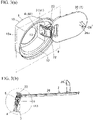
Figs. 1(a) and 1(b) show a lid device of an embodiment in a usual fully open position according to the present invention, whereinFig. 1(a) is a schematic perspective view; andFig. 1(b) is a schematic side view simplified by omitting a housing and a lid outer. -
Figs. 2(a) and 2(b) show a state wherein a lid has slightly turned by receiving a load in an opening direction further from the fully open position inFig. 1(a) , whereinFig. 2(a) is a schematic perspective view; andFig. 2(b) is a schematic side view simplified by omitting the housing and the lid outer. -
Figs. 3(a) and 3(b) show a state wherein the lid has turned by receiving an excessive load in the opening direction further fromFigs. 2(a) and 2(b) , whereinFig. 3(a) is a schematic perspective view; andFig. 3(b) is a schematic side view simplified by omitting the housing. -
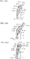
Fig. 4(a) is an enlarged view of an A1 portion inFig. 1(b) ;Fig. 4(b) is an enlarged view of an A2 portion inFig. 2(b) ; andFig. 4(c) is an enlarged view of an A3 portion inFig. 3(b) . -
Fig. 5 is a perspective view in a state wherein the lid inFigs. 3(a) and 3(b) is viewed from a different angle, and the housing and a second link member are omitted. -
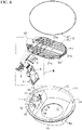
Fig. 6 is a schematic exploded perspective view showing a relation of members of the lid device. -
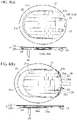
Figs. 7(a) and 7(b) show a structure of the lid, whereinFig. 7(a) is a perspective view showing a relation of a lid main member and the lid outer; andFig. 7(b) is a side view thereof. -
Fig. 8(a) is a top view and a side view of the fully open position in a state wherein the lid outer is assembled to the lid main member; andFig. 8(b) is a top view and a side view of an abnormal state wherein the lid outer is moved in a direction of deviating from the state inFig. 8(a) by receiving a load in an arrow direction, i.e. an excessive open state. -
Fig. 9 is a structural view showing a relation of the members wherein a B portion inFig. 6 is enlarged. -
Fig. 10(a) is a diagram showing a shaft structure of a link member; andFig. 10(b) is an explanatory drawing thereof. -
Fig. 11 is a schematic exploded view showing a structure (Fig. 5 ) of a lid device disclosed inPatent Document 1. -
Fig. 12 is a side cross-sectional view showing a structure (Fig. 3 ) disclosed in thePatent Document 1. - The best embodiment of the present invention will be explained with reference to the attached drawings. In an explanation, after a structure of a vehicle lid device according to the embodiment of the present invention is clarified, operation characteristics will be described. Incidentally, in
Figs. 1(b) and2(b) , andFigs. 4(a) and 4(b) , as alid 2, a lid outer 27 is omitted. Namely, in this stage, although the lid outer 27 is assembled to a lidmain member 20, the lid outer 27 is omitted so as to be simplified in the same manner as inFig. 3(b) andFig. 4(c) . - (Structure) In
Fig. 1(a) to Fig. 6 , the lid device comprises an approximately container-like housing 1 dividing aspace 12 disposing a fueling port or an electrical charging port and opening upwardly (in a use state, a near side is open); alid 2 opening and closing an upper opening of thehousing 1; abase member 4 held on an inner circumference side of thehousing 1 through afixture frame 3; and first andsecond link members lid 2 relative to thebase member 4 to be openable and closable. Also, thelid 2 is formed by the lidmain member 20 and the lid outer 27. Incidentally, thehousing 1, the lid 2 (the lidmain member 20 and the lid outer 27), thefixture frame 3, thebase member 4, and twolink members - In other words, in the lid device, the
lid 2 is supported relative to thehousing 1 to be turnable through thefixture frame 3 and thebase member 4, and twolink members lid 2 is locked in a closed position shown by imaginary lines of dashed lines inFig. 1(b) by a lock device (not shown in the drawing) mounted on an outer circumference of thehousing 1. For example, the locking is released by releasing the locking through an opener inside a vehicle compartment, or releasing in an association with a release operation of a door lock. From that state, thelid 2 slightly opens from the closed position inFig. 1(b) against an urging force of anurging device 7 such as a spring and the like by a push lifter (see Patent Document 1) not shown in the drawing. Then, in a middle of turning thelid 2 in an opening direction by hand, an urging direction of theurging device 7 is reversed, and after that, thelid 2 turns in a fully opening direction shown by solid lines inFig. 1(b) by the urging force of theurging device 7. Details are as follows. - As shown in
Fig. 1(a) , thehousing 1 includes aflange portion 11 protruding on an upper circumference of acylindrical portion 10, and for example, in the same manner as thePatent Document 1, in a state wherein thecylindrical portion 10 is inserted relative to an attachment frame (not shown in the drawing) attached to abody 9 side of an auto body from an opening of the relevant attachment frame, thehousing 1 is mounted through theflange portion 11, a seal member mounted on theflange portion 11, and the like. - Also, as shown in
Fig. 6 , thecylindrical portion 10 includes theinside space 12; a circular throughhole 13 at a bottom wall; aconcave portion 14 provided in an inner circumference and being capable of receiving thefixture frame 3; receivingportions 18 located on an inner circumference, and provided on both sides sandwiching theconcave portion 14 and facing theconcave portion 14 so as to hold thelid 2 in the closed position;cavity portions 17 wherein one part of thereceiving portions 18 on both sides sandwiching theconcave portion 14 is formed slightly lower; and anarrangement portion 10a provided on a side opposite to theconcave portion 14 in the outer circumference. - In the
arrangement portion 10a, there are disposed the lock device (not shown in the drawings) for engaging/disengaging thelid 2 with/from the closed position, the push lifter (not shown in the drawings) for rising thelid 2 by slightly pushing thelid 2 up when thelid 2 is opened from the closed position, and the like, as necessity. On the other hand, thespace 12 is a portion for disposing the fueling port or the electrical charging port. In thethrough hole 13, for example, there is disposed a connecting pipe for communicating with a fuel tank side, or an electrical charging mechanism portion. In theconcave portion 14, there are provided projectingpiece portions 15 integrated with inner faces on both sides and projecting upwardly; rail-likeconvex portions 16 facing each other on both inner faces including the projectingpiece portions 15; andattachment holes 19. - As shown in
Figs. 7(a) and 7(b) , andFigs. 8(a) and 8(b) , thelid 2 is formed by the lidmain member 20 to which therespective link members main member 20, and in a fully open position (Fig. 8(a) ), in a case wherein an external force at a predetermined value or above is applied to the lidmain member 20 in the opening direction (Fig. 8(b) ), thelid 2 is formed such that the lid outer 27 moves in a direction of falling off from the lidmain member 20 or separating from therespective link members base member 4, thehousing 1, and the like. - Specifically, first, the lid outer 27 forms a design surface of the
lid 2, and includes aU-shaped rib 28 located on a circumference side on a lower face and provided on a front side from a middle; a plurality of engagedportions 28a provided on both inside facing faces of therib 28; and a pair ofelastic projections 29 provided on a back side. On the other hand, the lidmain member 20 provides a pair ofarm portions 22 on a back side of aflat plate 21 with agap 20a. On an upper face of theflat plate 21, there are included an arc-shapedrib 21a provided on a front-side circumference;arcuate ribs 21b provided in both circumference portions on the back side; arib 21c positioned in a middle of right and left and provided on a front side of therib 21a; and many reinforcing ribs provided inside therib 21a and both theribs 21b. Also, there is included a plurality of lockingpiece portions 23a respectively provided on both sides of therib 21a. Eachlocking piece portion 23a forms a locking space opening a front side, and engaging with/disengaging from the corresponding engagedportion 28a of the lid outer. - Also, on a lower face of the
flat plate 21, an engagement piece 26' projects approximately in a middle of a plate width on a front side. The engagement piece 26' includes alocking hole 26a' passing through in front and back, and a lock member of the aforementioned lock device is inserted and engaged so as to lock thelid 2 in a closed state. A corresponding portion of therespective link members left arm portions 22. - Both the
arm portions 22 are formed to become thicker up and down as coming to a back end side, and includenotch portions 22a engaging with/disengaging from the aforementionedelastic projections 29 on an outside face. Consequently, as shown inFig. 8(a) , the lid outer 27 is assembled relative to the lidmain member 20 by an engagement between the respectivelocking piece portions 23a and engagedportions 28a and an engagement between therespective notch portions 22a andelastic projections 29 as thelid 2. - As shown in
Fig. 9 , on a facing inner face of eacharm portion 22, there are provided ahole 24 and ahole 25 in front and back respectively on a coaxial line by maintaining an interval. Among those, as shown inFigs. 10(a) and 10(b) , thehole 24 is positioned on a front side and a side upper than thehole 25, and engages a correspondingshaft 54 of the later-describedfirst link member 5. Thereference numeral 24a represents a groove portion for guiding theshaft 54 to thehole 24 from an upper side of thearm portion 22 so as to be fittable. Thehole 25 engages a correspondingshaft 64 of the later-describedsecond link member 6. Thereference numeral 26 represents a groove portion for fitting theshaft 64 into thehole 25, or for allowing theshaft 64 to fit into thehole 25 again from a state disengaged from thehole 25. - The
groove portion 26 includes aninsertion portion 26a having an upper end open, located between an upper end and thehole 25, and formed in the lowest on an upper end side; a retaining portion 26c forming an edge portion of thehole 25, and formed in the highest; and aninclined portion 26b formed between theinsertion portion 26a and the retaining portion 26c. The aforementioned structure is one example wherein in a state where theshaft 64 is fitted into thehole 25, when receiving stress in an disengaging direction, the fitting of theshaft 64 is released from the retaining portion 26c to theinclined portion 26b, and theshaft 64 easily moves to theinsertion portion 26a. In this structure, on the upper end side of theinsertion portion 26a, there is further provided astopper portion 26d located higher than the relevant insertion portion for preventing theshaft 64 from coming off. Thestopper portion 26d is for preventing ashaft portion 65 from completely coming off from the upper end unintentionally even when the fitting of theshaft portion 65 is released from thehole portion 24 so as to move to theinsertion portion 26a. - As shown in
Fig. 9 , thefixture frame 3 has an approximately C shape formed by aconnection piece 30 and bothside pieces 31 which can be housed in theconcave portion 14. Theconnection piece 30 includes a pair ofprojection portions 33 positioned on an upper face side and provided withgaps 32 between theprojection portions 33 and theside pieces 31; attachment holes (not shown in the drawing) provided on a front end face and overlapping with the attachment holes 19 on a housing side; and a plurality of receivingportions 30a provided on a back end face. The receivingportions 30a have a height which becomes approximately one surface with the back end face of bothside pieces 31. In eachgap 32, there is provided a locking portion (not shown in the drawing) where anelastic locking piece 43 of the later-described base member engages and disengages. Eachside wall 31 includes alongitudinal groove 34 provided on an outer face and extending to just before an upper end from a lower end; and aninsertion hole 35 provided on an upper side of eachlongitudinal groove 34 and passing through on a coaxial line. - The
aforementioned fixture frame 3 engages while sliding eachlongitudinal groove 34 in the corresponding rail-likeconvex portion 16 so as to be mounted relative to theconcave portion 14 on the housing side. Also, as necessity, thefixture frame 3 is fastened and fixed by a fastener such as a screw and the like (not shown in the drawing). In this operation, the fastener is screwed into the attachment holes 19 and the attachment holes provided in theaforementioned connection piece 30 from an outside of thehousing 1. - The
base member 4 has a size which can be approximately housed inside the C shape of thefixture frame 3, and includes C-shaped insidewalls 40 provided in a middle and being capable of accepting alower portion 61 of thesecond link member 6;outside walls gaps 44 on both sides of theinside walls 40; aback end wall 42 closing between both theoutside walls 41;elastic locking pieces 43 provided in a cantilever state on a lower side of the respectiveoutside walls 41; insertion holes 46 provided on an upper side of the respectiveoutside walls 41 and passing through on a coaxial line; and shaft holes 47 provided upper-side facing portions of theinside wall 40 and passing through on the coaxial line. - The
aforementioned base member 4 is pushed into thefixture frame 3 such that both theoutside walls 41 fit into an inside of thecorresponding side pieces 31. Then, in thebase member 4, a lower side of theinside walls 40 moveably fits into the correspondingprojection portions 33, and the respectiveelastic locking pieces 43 disengageably engage the locking portions inside thegaps 32. Next, in thebase member 4, pins 8 are inserted into the insertion holes 46 on a base member side from the insertion holes 35 on a fixture frame side relative to thefixture frame 3. Then, thebase member 4 is supported in thefixture frame 3 in a state wherein theback end wall 42 is positioned between both theside pieces 31 and abuts against therespective receiving portions 30a. Incidentally, structurally, it may be simplified by omitting thefixture frame 3, and directly fixing and placing thebase member 4 in theconcave portion 14 of the housing. - The
first link member 5 and thesecond link member 6 are turnably supported relative to thebase member 4. Namely, as shown inFig. 9 , thefirst link member 5 has an approximately L shape in a side view, an outer face side is the design surface, and an inner face side becomes an arrangement portion for an urging member. As a shape, thefirst link member 5 includes aplate portion 50 on an upper side, andleg portions 51 projecting obliquely downward from both lower sides of theplate portion 50. In theplate portion 50, there are provided theshaft portions holes support shaft portions respective leg portions 51 are disposed in the correspondinggaps 44 on the base member side. - In the aforementioned
first link member 5, relative to thebase member 4, in a state wherein theholes 55 on both sides are superposed on the corresponding insertion holes 46 of the base member, thepins 8 are turnably fitted into theholes 55 through the insertion holes 35 on the fixture frame side and the insertion holes 46 on the base member side. At that time, as an urgingmember 7, a coil spring is assembled in a state of holding a windingportion 7a in thesupport shaft portions 56 on both inner sides, wherein oneend 7b is disposed in an inner face of thecorresponding leg portion 51, and the other end 7c is disposed inside thegap 44 through a piece portion provided between theoutside wall 41 on a corresponding side and theinside wall 40 forming the base member, and connecting therebetween. - On the other hand, as shown in
Fig. 9 , thesecond link member 6 is formed by a wideupper portion 60; the narrowlower portion 61; and projectingportions upper portion 60. On an outer face of the respective projectingportions 63, there is projected theshafts 64 on a coaxial line. On both outside faces of thelower portion 61, there are projected theshafts 65 on a coaxial line. - In the aforementioned
second link member 6, relative to the lidmain member 20, the respective projectingportions 63 are disposed between thearm portion 22 and thearm portion 22 of the lid, and theshafts 64 are fitted into the correspondingholes 25 to be turnable. Also, therespective shafts 65 on a lower side are fitted and turnably connected to the correspondingholes 47 of the base member. - (Operation) Next, the operation characteristics of the aforementioned lid device are clarified with reference to
Fig. 1(a) to Fig. 5 , and the like. - (1)
Figs. 1(a) and 1(b) show a basic operation of the lid device. InFig. 1(b) , the basic operation resides in that thelid 2 is switched between the closed position shown by the dashed lines where thelid 2 becomes approximately a same one face as a body of an auto body, and the fully open position shown by the solid lines; in the closed position, thelid 2 is urged in a closing direction by the urging force of the urgingmember 7, and is locked by the lock device (not shown in the drawings); when the lock device is unlocked, thelid 2 is pressed in the opening direction against an urging force of anurging device 6 by the push lifter (not shown in the drawings) so as to slightly turn in the opening direction as shown inFig. 1(b) ; and from that state, when an operator turns thelid 2 in the opening direction by hand and the like, in a middle (an intermediate position) of turning thelid 2, the urging direction of the urgingdevice 7 is reversed, and after that, thelid 2 turns in the opening direction through therespective link members device 7 until thelid 2 fully opens. - (2) Also, in the structure, in a fully open state of the
lid 2 through the first andsecond link members second link member 6 abuts against the inside of the L shape of thefirst link member 5, and an edge portion on a base end side of the lid outer 27 abuts against thesecond link member 6, so that thelid 2 is stably held in the fully open position where thelid 2 opens at 90 degrees or more. The structure excels in the appearance because in the fully open position thereof, thesecond link member 6 is in a state clamped between thelid 2 and thefirst link member 5 so as to be difficult to be seen; thefirst link member 5 includes a flat design surface on aspace 12 side; and the like. These characteristics are similar to those of thePatent Document 1. Next, specific operations or advantages of the structure will be described. - (3) In the aforementioned lid device, in the fully open position of the
lid 2 inFigs. 1(a) and 1(b) , even in a case wherein thelid 2 receives an external force F in the opening direction further, and turns forcibly as shown inFigs. 3(a) and 3(b) , a damage, i.e. a breakage, a dent, a scratch, or the like, that structural members or the body of the auto body receive can be minimized by operations as described hereinafter. - First, in the structure, as shown in
Figs. 2(a) and 2(b) as an example, when thelid 2 receives the external force F in the opening direction further from the fully open position, and slightly turns, thebase member 4 receives a load from therespective link members pins 8 and to mitigate and absorb the load. - Incidentally, in the
base member 4, theelastic locking pieces 43 elastically engage/disengage relative to the locking portions on the fixture frame side, so that thebase member 4 can return to an original state only by pushing and operating thebase member 4 backward again from a state inFigs. 2(a) and 2(b) . Such an operation becomes effective in preventing the breakage or minimizing the damage on thelink members base member 4 as the support point by thepins 8 so as to improve a quality and reliability. - Secondly,
Figs. 3(a) and 3(b) show a state wherein thelid 2 has largely turned by receiving an excessive external force in the opening direction further from the state inFigs. 2(a) and 2(b) . In this process, as shown inFig. 3(b) , especially, therespective link members shafts 64 of theupper portion 60 are disengaged from theholes 25, and move to theaforementioned groove portion 26, specifically, the retaining portion 26c, theinclined portion 26b, and theinsertion portion 26a inFig. 10(a) . As a result, in the structure, the external force or stress which thelid 2 receives is mitigated and absorbed by the disengagement between theshafts 64 and theholes 25 so as to prevent the breakage or suppress the damage on thelink members - Incidentally, in the structure, by a presence of the
stopper portion 26d, theshafts 64 are not allowed to come off completely from thegroove portion 26, so that in a process of turning thelid 2 in the closing direction again, thelid 2 comes to automatically fit into thehole 25. - Thirdly, almost simultaneously, in the structure, when the
lid 2 turns in the opening direction further from the state inFigs. 2(a) and 2(b) , the lid outer 27 forming thelid 2 abuts against thelink members base member 4, the body of the auto body, and the like, and receives an external force in an arrow direction inFig. 8(b) . As a result, in the lid outer 27, the engagedportions 28a are disengaged from thelocking piece portions 23a, and theelastic projections 29 are disengaged from thenotch portions 22a, so that the lid outer 27 falls off from the lidmain member 20, or moves in a direction of separating from the first andsecond link members lid 2 excessively turns in the opening direction further from the fully open position, the external force applied to the lid outer 27 is mitigated and absorbed, thereby preventing or minimizing the damage on the lid outer 27, the body of the auto body, and the like. Furthermore, in the structure, a user has an advantage such that since the lid outer 27 comes off from the lidmain member 20, or moves in the direction of separating from the first andsecond link members - Incidentally, in the structure, even if the lid outer 27 comes off from the lid
main member 20, the lid outer 27 can be easily assembled relative to the lidmain member 20 as mentioned above by the engagement between the respectivelocking piece portions 23a and the engagedportions 28a, and the engagement between therespective notch portions 22a and theelastic projections 29. - As described above, the vehicle lid device according to the present invention can be variously modified except for specified requirements within a range described in the invention. For example, as for the
lid 2, theouter lid 27 moves in the direction of separating from thelink members main member 20; however, it is further preferable that theouter lid 27 is formed in such a way so as not to come off unintentionally. Also, thefirst link member 5 includes theholes 55, and thepins 8 are mounted into the corresponding insertion holes 46 of thebase member 4 through theholes 55 using thepin members 8 which are the shafts; however, in place of theholes 55 and thepins 8, shafts such as theshafts holes 46 on the base member side. - Also, as for an opening/closing operation of the
lid 2, it is not limited to the embodiment, and for example, it can be formed such that thelid 2 slightly turns in the opening direction by the urging force of the urging member by unlocking the lock device (not shown in the drawings) in the closed position as well. Furthermore, in a case of being simplified, for example, thefixture frame 3 may be omitted, and thebase member 4 may be directly supported by the corresponding concave portion (a shape of the concave portion becomes a shape such that thefixture frame 3 is mounted on the concave portion 14) of thehousing 1 as well. -
- 1
- a housing
- 2
- a lid (20 is a lid main member, and 27 is a lid outer)
- 3
- a fixture frame (30 is a bottom wall, 31 is side walls, and 34 is engagement grooves)
- 4
- a base member (40 is a main member, 41 is side walls, and 43 is elastic locking pieces)
- 5
- a first link member (50 is a plate portion, and 51 is leg portions)
- 6
- a second link member (60 is an upper portion, and 61 is a lower portion)
- 7
- an urging member (7a is a winding portion, 7b is one end, and 7d is the other end)
- 8
- pins (corresponding to shafts)
- 9
- a body of an auto body
- 10
- a cylindrical portion (14 is a concave portion)
- 12
- a space for a fueling port or an electrical charging port
- 20
- a lid main member (22 is arm portions)
- 24
- holes (24a is groove portions)
- 25
- holes
- 26
- groove portions
- 27
- a lid outer (28 is a rib, and 28a is engaged portions)
- 35
- pin insertion holes
- 46
- pin insertion holes
- 47
- shaft holes
- 54
- shafts (shafts having an approximately D shape in a cross section)
- 55
- holes
- 56
- support shaft portions
- 64
- shafts (shafts having an approximately round shape in a cross section)
- 65
- shafts
Claims (7)
- A vehicle lid device, comprising:a housing (1) disposing a fueling port or an electrical charging port inside an opening; anda lid (2) turnably connected to a housing side, and opening and closing the opening of the housing (1),wherein a connection portion between the housing side and a lid side includes a fitting portion for a shaft (64) and a hole (25), and in a fully open position of the lid (2), when an external force at a predetermined value or above is applied in an opening direction to further open the lid (2), fitting of the fitting portion is released, wherein the lid (2) is connected and supported relative to the housing (1) through a first link member (5) and a second link member (6) including a shaft (64), said vehicle lid device being characterized by comprising a groove portion including a retaining portion (26c), an inclined portion (26b) and an insertion portion (26a) provided on the lid side and in that when the link members (5, 6) come close to each other and hit each other, the shaft (64) of an upper portion (60) is adapted to be disengaged from the hole (25), and to move to said groove portion (26)
- A vehicle lid device according to claim 1, wherein when the external force at the predetermined value or above is applied, fitting of the fitting portion between the second link member (6) and the lid (2) is released, and fitting of the fitting portion between the first link member (5) and the lid (2) is maintained.
- A vehicle lid device according to claim 2, further comprising an urging member (7) supported in the first link member (5).
- A vehicle lid device according to claim 2 or 3, wherein as the shaft, the first link member (5) includes a shaft (54) having an approximately D shape in a cross section, and the second link member (6) includes said shaft (64) having an
approximately round shape in a cross section which can be released from the fitting easier than the D shape. - A vehicle lid device according to any one of claims 1 to 4, further comprising said groove portion (26) provided on the
lid side for allowing the shaft (64) of the second link member (6) to fit again from a state wherein the shaft (64) of the second link member (6) has come off from the hole portion (24). - A vehicle lid device according to any one of claims 2 to 5, wherein the lid (2) includes a lid main member (20) to which the first and second link members (5, 6) are connected, and a lid outer (27) mounted on an outer face of the lid main member (20), and in a case wherein an external force at a predetermined value or above in an opening direction is applied to the lid main member (20), the lid outer (27) falls off from the lid main member (20), or moves in a direction of separating from the first and second link members (5, 6).
- A vehicle lid device according to any one of claims 1 to 6, wherein in a base member (4), elastic locking pieces (43) elastically engage/disengage relative to locking portions on a fixture frame side, so that the base member (4) can return to an original state only by pushing and operating the base member (4) backward again.
Applications Claiming Priority (2)
| Application Number | Priority Date | Filing Date | Title |
|---|---|---|---|
| JP2017137908A JP6689236B2 (en) | 2017-07-14 | 2017-07-14 | Vehicle lid device |
| PCT/JP2018/025998 WO2019013193A1 (en) | 2017-07-14 | 2018-07-10 | Lid device for vehicle |
Publications (3)
| Publication Number | Publication Date |
|---|---|
| EP3653425A1 EP3653425A1 (en) | 2020-05-20 |
| EP3653425A4 EP3653425A4 (en) | 2021-02-17 |
| EP3653425B1 true EP3653425B1 (en) | 2022-03-30 |
Family
ID=65001701
Family Applications (1)
| Application Number | Title | Priority Date | Filing Date |
|---|---|---|---|
| EP18832613.6A Active EP3653425B1 (en) | 2017-07-14 | 2018-07-10 | Lid device for vehicle |
Country Status (6)
| Country | Link |
|---|---|
| US (1) | US11214141B2 (en) |
| EP (1) | EP3653425B1 (en) |
| JP (1) | JP6689236B2 (en) |
| CN (1) | CN110891817B (en) |
| ES (1) | ES2915581T3 (en) |
| WO (1) | WO2019013193A1 (en) |
Families Citing this family (12)
| Publication number | Priority date | Publication date | Assignee | Title |
|---|---|---|---|---|
| JP6709760B2 (en) * | 2017-07-14 | 2020-06-17 | 株式会社ニフコ | Vehicle lid device |
| KR102484859B1 (en) * | 2017-12-12 | 2023-01-05 | 현대자동차주식회사 | Radiatir grille rechargeable door apparatus for a vehicle |
| DE102018125209A1 (en) * | 2018-10-11 | 2020-04-16 | Bayerische Motoren Werke Aktiengesellschaft | Tank or tailgate assembly |
| JP7518003B2 (en) | 2021-01-12 | 2024-07-17 | 株式会社アルファ | Lid device |
| KR20230087731A (en) * | 2021-12-10 | 2023-06-19 | 에스엘 주식회사 | Charge port door |
| JP7704072B2 (en) * | 2022-05-26 | 2025-07-08 | 豊田合成株式会社 | Lid device for vehicle |
| JP7726168B2 (en) * | 2022-09-28 | 2025-08-20 | 豊田合成株式会社 | Lid assembly structure |
| FR3151253B1 (en) * | 2023-07-19 | 2025-06-13 | Psa Automobiles Sa | Fuel or electrical charging port hatch with a rib at the plastic injection point |
| WO2025018335A1 (en) * | 2023-07-20 | 2025-01-23 | 株式会社パイオラックス | Opening/closing device for opening/closing body |
| US20260022599A1 (en) * | 2024-07-17 | 2026-01-22 | GM Global Technology Operations LLC | Dual gooseneck hinge assembly for a door cover |
| JP2026051949A (en) * | 2024-09-10 | 2026-03-23 | 株式会社ユーシン | Lid device |
| CN119333016B (en) * | 2024-12-18 | 2025-05-13 | 宁波市长伦世纪电子科技有限公司 | Charging flap opening and closing device of new energy automobile |
Family Cites Families (29)
| Publication number | Priority date | Publication date | Assignee | Title |
|---|---|---|---|---|
| JP2530321Y2 (en) * | 1992-02-07 | 1997-03-26 | アラコ株式会社 | Movable fuel lid mounting structure |
| JP2929868B2 (en) * | 1992-10-26 | 1999-08-03 | トヨタ自動車株式会社 | Vehicle fuel filler structure |
| DE29605297U1 (en) * | 1996-03-21 | 1996-05-23 | Mittelhäuser, Bernhard, 30900 Wedemark | Device for covering the filler neck on motor vehicles by means of a fuel filler flap |
| US6315144B1 (en) * | 1997-04-08 | 2001-11-13 | Stant Manufacturing Inc. | Contaminant cover for tank filler neck closure |
| US7258386B2 (en) * | 1999-04-27 | 2007-08-21 | 89908, Inc. | Fuel door assembly |
| JP3725024B2 (en) * | 2000-12-14 | 2005-12-07 | ホシデン株式会社 | Lid opening / closing structure |
| JP4269750B2 (en) * | 2003-04-02 | 2009-05-27 | 豊田合成株式会社 | Cap device |
| CN100364799C (en) * | 2004-06-04 | 2008-01-30 | 雅马哈发动机株式会社 | Fuel tank cap assembly and vehicle having same |
| CA2516139C (en) * | 2005-08-15 | 2011-03-15 | Van-Rob Inc. | Automotive fuel door assembly |
| JP4207964B2 (en) * | 2006-01-27 | 2009-01-14 | トヨタ自動車株式会社 | Gas fuel filling lid device for vehicle |
| JP2010203208A (en) * | 2009-03-06 | 2010-09-16 | Toyota Auto Body Co Ltd | Lid member opening and closing structure for vehicle |
| JP2010215076A (en) * | 2009-03-16 | 2010-09-30 | Daihatsu Motor Co Ltd | Fuel filling device in vehicle |
| JP5678474B2 (en) * | 2010-05-25 | 2015-03-04 | スズキ株式会社 | Charging connector |
| JP5342515B2 (en) * | 2010-06-28 | 2013-11-13 | 本田技研工業株式会社 | Charging port structure and saddle-ride type vehicle |
| JP2012232707A (en) * | 2011-05-09 | 2012-11-29 | Suzuki Motor Corp | Charging port structure |
| JP5780121B2 (en) * | 2011-11-02 | 2015-09-16 | 三菱自動車工業株式会社 | Lid mounting structure |
| US9327594B2 (en) * | 2013-08-15 | 2016-05-03 | GM Global Technology Operations LLC | Access system for vehicle energy storage device with magnetic sensor to detect access door position |
| WO2015076898A1 (en) * | 2013-11-19 | 2015-05-28 | Illinois Tool Works Inc. | A fuel filler assembly for a vehicle |
| DE202014002556U1 (en) * | 2014-03-22 | 2015-06-26 | GM Global Technology Operations LLC (n. d. Ges. d. Staates Delaware) | Flap arrangement for a motor vehicle |
| FR3021259B1 (en) * | 2014-05-23 | 2016-05-13 | Renault Sa | TRAPPER FOR THE SEALING OF ACCESS TO A POWER SUPPLY INTERFACE OF A MOTOR VEHICLE. |
| US9376012B2 (en) * | 2014-10-13 | 2016-06-28 | Srg Global, Inc. | Vehicle fuel filler system seal |
| JP2016094096A (en) * | 2014-11-14 | 2016-05-26 | 三菱自動車工業株式会社 | Lid device |
| JP6466293B2 (en) | 2015-09-03 | 2019-02-06 | 株式会社ニフコ | Vehicle lid device |
| KR101823899B1 (en) * | 2015-12-24 | 2018-01-31 | 현대자동차주식회사 | Structure of opening and closing fuel door |
| JP2017137908A (en) | 2016-02-02 | 2017-08-10 | 本田技研工業株式会社 | Electromagnetic valve control device and electromagnetic fuel injection valve |
| IT201600104772A1 (en) * | 2016-10-18 | 2018-04-18 | Cebi Italy Spa | SYSTEM FOR THE CLOSING OF A DOOR OF THE FUEL TANK. |
| CN206242908U (en) * | 2016-10-21 | 2017-06-13 | 北京汽车股份有限公司 | Oiling lid arrangement for vehicle and the vehicle with it |
| KR102484859B1 (en) * | 2017-12-12 | 2023-01-05 | 현대자동차주식회사 | Radiatir grille rechargeable door apparatus for a vehicle |
| KR102602955B1 (en) * | 2018-09-21 | 2023-11-16 | 현대자동차주식회사 | Fuel door apparatus for vehicle |
-
2017
- 2017-07-14 JP JP2017137908A patent/JP6689236B2/en active Active
-
2018
- 2018-07-10 ES ES18832613T patent/ES2915581T3/en active Active
- 2018-07-10 CN CN201880046443.0A patent/CN110891817B/en active Active
- 2018-07-10 EP EP18832613.6A patent/EP3653425B1/en active Active
- 2018-07-10 US US16/630,260 patent/US11214141B2/en active Active
- 2018-07-10 WO PCT/JP2018/025998 patent/WO2019013193A1/en not_active Ceased
Also Published As
| Publication number | Publication date |
|---|---|
| JP2019018673A (en) | 2019-02-07 |
| CN110891817B (en) | 2023-02-17 |
| CN110891817A (en) | 2020-03-17 |
| US20200130505A1 (en) | 2020-04-30 |
| ES2915581T3 (en) | 2022-06-23 |
| EP3653425A4 (en) | 2021-02-17 |
| JP6689236B2 (en) | 2020-04-28 |
| EP3653425A1 (en) | 2020-05-20 |
| WO2019013193A1 (en) | 2019-01-17 |
| US11214141B2 (en) | 2022-01-04 |
Similar Documents
| Publication | Publication Date | Title |
|---|---|---|
| EP3653425B1 (en) | Lid device for vehicle | |
| US10513174B2 (en) | Vehicle lid device | |
| US8353549B2 (en) | Push button mechanism for opening and closing a storage compartment for a vehicle | |
| US8933332B2 (en) | Arrangement structure for charging port cover | |
| RU2527882C1 (en) | Layout structure for casing of charging port | |
| CN104145071B (en) | The locking system of open-close body | |
| JP6709760B2 (en) | Vehicle lid device | |
| JP6826696B2 (en) | Fuel lid opener | |
| US11479113B2 (en) | Fuel door opener assembly | |
| US9222291B2 (en) | Toggle type fastener | |
| US11767693B2 (en) | Lid opening and closing device for a vehicle | |
| US12128757B2 (en) | Lid assembly structure | |
| JP6709827B2 (en) | Vehicle lid device | |
| US11279224B2 (en) | Lid opening and closing device for vehicle | |
| JPWO2019234985A1 (en) | Lid lock mechanism and washing machine using it | |
| KR100693740B1 (en) | Locking mechanism release mechanism | |
| JP6197199B2 (en) | Door latch device for automobile | |
| WO2008056573A1 (en) | Lock device | |
| KR101619985B1 (en) | Hinge device of towing hook cap for bumper cover | |
| JP2007092274A (en) | Door opener | |
| HK1205082B (en) | A plug body of a beverage container |
Legal Events
| Date | Code | Title | Description |
|---|---|---|---|
| STAA | Information on the status of an ep patent application or granted ep patent |
Free format text: STATUS: THE INTERNATIONAL PUBLICATION HAS BEEN MADE |
|
| PUAI | Public reference made under article 153(3) epc to a published international application that has entered the european phase |
Free format text: ORIGINAL CODE: 0009012 |
|
| STAA | Information on the status of an ep patent application or granted ep patent |
Free format text: STATUS: REQUEST FOR EXAMINATION WAS MADE |
|
| 17P | Request for examination filed |
Effective date: 20200121 |
|
| AK | Designated contracting states |
Kind code of ref document: A1 Designated state(s): AL AT BE BG CH CY CZ DE DK EE ES FI FR GB GR HR HU IE IS IT LI LT LU LV MC MK MT NL NO PL PT RO RS SE SI SK SM TR |
|
| AX | Request for extension of the european patent |
Extension state: BA ME |
|
| DAV | Request for validation of the european patent (deleted) | ||
| DAX | Request for extension of the european patent (deleted) | ||
| A4 | Supplementary search report drawn up and despatched |
Effective date: 20210119 |
|
| RIC1 | Information provided on ipc code assigned before grant |
Ipc: B60K 1/04 20190101ALI20210113BHEP Ipc: F02M 37/00 20060101ALI20210113BHEP Ipc: B60K 15/05 20060101AFI20210113BHEP |
|
| GRAP | Despatch of communication of intention to grant a patent |
Free format text: ORIGINAL CODE: EPIDOSNIGR1 |
|
| STAA | Information on the status of an ep patent application or granted ep patent |
Free format text: STATUS: GRANT OF PATENT IS INTENDED |
|
| INTG | Intention to grant announced |
Effective date: 20211217 |
|
| GRAS | Grant fee paid |
Free format text: ORIGINAL CODE: EPIDOSNIGR3 |
|
| GRAA | (expected) grant |
Free format text: ORIGINAL CODE: 0009210 |
|
| STAA | Information on the status of an ep patent application or granted ep patent |
Free format text: STATUS: THE PATENT HAS BEEN GRANTED |
|
| AK | Designated contracting states |
Kind code of ref document: B1 Designated state(s): AL AT BE BG CH CY CZ DE DK EE ES FI FR GB GR HR HU IE IS IT LI LT LU LV MC MK MT NL NO PL PT RO RS SE SI SK SM TR |
|
| REG | Reference to a national code |
Ref country code: GB Ref legal event code: FG4D |
|
| REG | Reference to a national code |
Ref country code: CH Ref legal event code: EP |
|
| REG | Reference to a national code |
Ref country code: AT Ref legal event code: REF Ref document number: 1478873 Country of ref document: AT Kind code of ref document: T Effective date: 20220415 |
|
| REG | Reference to a national code |
Ref country code: DE Ref legal event code: R096 Ref document number: 602018033126 Country of ref document: DE |
|
| REG | Reference to a national code |
Ref country code: IE Ref legal event code: FG4D |
|
| REG | Reference to a national code |
Ref country code: ES Ref legal event code: FG2A Ref document number: 2915581 Country of ref document: ES Kind code of ref document: T3 Effective date: 20220623 |
|
| REG | Reference to a national code |
Ref country code: LT Ref legal event code: MG9D |
|
| PG25 | Lapsed in a contracting state [announced via postgrant information from national office to epo] |
Ref country code: SE Free format text: LAPSE BECAUSE OF FAILURE TO SUBMIT A TRANSLATION OF THE DESCRIPTION OR TO PAY THE FEE WITHIN THE PRESCRIBED TIME-LIMIT Effective date: 20220330 Ref country code: RS Free format text: LAPSE BECAUSE OF FAILURE TO SUBMIT A TRANSLATION OF THE DESCRIPTION OR TO PAY THE FEE WITHIN THE PRESCRIBED TIME-LIMIT Effective date: 20220330 Ref country code: NO Free format text: LAPSE BECAUSE OF FAILURE TO SUBMIT A TRANSLATION OF THE DESCRIPTION OR TO PAY THE FEE WITHIN THE PRESCRIBED TIME-LIMIT Effective date: 20220630 Ref country code: LT Free format text: LAPSE BECAUSE OF FAILURE TO SUBMIT A TRANSLATION OF THE DESCRIPTION OR TO PAY THE FEE WITHIN THE PRESCRIBED TIME-LIMIT Effective date: 20220330 Ref country code: HR Free format text: LAPSE BECAUSE OF FAILURE TO SUBMIT A TRANSLATION OF THE DESCRIPTION OR TO PAY THE FEE WITHIN THE PRESCRIBED TIME-LIMIT Effective date: 20220330 Ref country code: BG Free format text: LAPSE BECAUSE OF FAILURE TO SUBMIT A TRANSLATION OF THE DESCRIPTION OR TO PAY THE FEE WITHIN THE PRESCRIBED TIME-LIMIT Effective date: 20220630 |
|
| REG | Reference to a national code |
Ref country code: NL Ref legal event code: MP Effective date: 20220330 |
|
| REG | Reference to a national code |
Ref country code: AT Ref legal event code: MK05 Ref document number: 1478873 Country of ref document: AT Kind code of ref document: T Effective date: 20220330 |
|
| PG25 | Lapsed in a contracting state [announced via postgrant information from national office to epo] |
Ref country code: LV Free format text: LAPSE BECAUSE OF FAILURE TO SUBMIT A TRANSLATION OF THE DESCRIPTION OR TO PAY THE FEE WITHIN THE PRESCRIBED TIME-LIMIT Effective date: 20220330 Ref country code: GR Free format text: LAPSE BECAUSE OF FAILURE TO SUBMIT A TRANSLATION OF THE DESCRIPTION OR TO PAY THE FEE WITHIN THE PRESCRIBED TIME-LIMIT Effective date: 20220701 Ref country code: FI Free format text: LAPSE BECAUSE OF FAILURE TO SUBMIT A TRANSLATION OF THE DESCRIPTION OR TO PAY THE FEE WITHIN THE PRESCRIBED TIME-LIMIT Effective date: 20220330 |
|
| PG25 | Lapsed in a contracting state [announced via postgrant information from national office to epo] |
Ref country code: NL Free format text: LAPSE BECAUSE OF FAILURE TO SUBMIT A TRANSLATION OF THE DESCRIPTION OR TO PAY THE FEE WITHIN THE PRESCRIBED TIME-LIMIT Effective date: 20220330 |
|
| PG25 | Lapsed in a contracting state [announced via postgrant information from national office to epo] |
Ref country code: SM Free format text: LAPSE BECAUSE OF FAILURE TO SUBMIT A TRANSLATION OF THE DESCRIPTION OR TO PAY THE FEE WITHIN THE PRESCRIBED TIME-LIMIT Effective date: 20220330 Ref country code: SK Free format text: LAPSE BECAUSE OF FAILURE TO SUBMIT A TRANSLATION OF THE DESCRIPTION OR TO PAY THE FEE WITHIN THE PRESCRIBED TIME-LIMIT Effective date: 20220330 Ref country code: RO Free format text: LAPSE BECAUSE OF FAILURE TO SUBMIT A TRANSLATION OF THE DESCRIPTION OR TO PAY THE FEE WITHIN THE PRESCRIBED TIME-LIMIT Effective date: 20220330 Ref country code: PT Free format text: LAPSE BECAUSE OF FAILURE TO SUBMIT A TRANSLATION OF THE DESCRIPTION OR TO PAY THE FEE WITHIN THE PRESCRIBED TIME-LIMIT Effective date: 20220801 Ref country code: EE Free format text: LAPSE BECAUSE OF FAILURE TO SUBMIT A TRANSLATION OF THE DESCRIPTION OR TO PAY THE FEE WITHIN THE PRESCRIBED TIME-LIMIT Effective date: 20220330 Ref country code: CZ Free format text: LAPSE BECAUSE OF FAILURE TO SUBMIT A TRANSLATION OF THE DESCRIPTION OR TO PAY THE FEE WITHIN THE PRESCRIBED TIME-LIMIT Effective date: 20220330 Ref country code: AT Free format text: LAPSE BECAUSE OF FAILURE TO SUBMIT A TRANSLATION OF THE DESCRIPTION OR TO PAY THE FEE WITHIN THE PRESCRIBED TIME-LIMIT Effective date: 20220330 |
|
| PGFP | Annual fee paid to national office [announced via postgrant information from national office to epo] |
Ref country code: ES Payment date: 20220819 Year of fee payment: 5 |
|
| PG25 | Lapsed in a contracting state [announced via postgrant information from national office to epo] |
Ref country code: PL Free format text: LAPSE BECAUSE OF FAILURE TO SUBMIT A TRANSLATION OF THE DESCRIPTION OR TO PAY THE FEE WITHIN THE PRESCRIBED TIME-LIMIT Effective date: 20220330 Ref country code: IS Free format text: LAPSE BECAUSE OF FAILURE TO SUBMIT A TRANSLATION OF THE DESCRIPTION OR TO PAY THE FEE WITHIN THE PRESCRIBED TIME-LIMIT Effective date: 20220730 Ref country code: AL Free format text: LAPSE BECAUSE OF FAILURE TO SUBMIT A TRANSLATION OF THE DESCRIPTION OR TO PAY THE FEE WITHIN THE PRESCRIBED TIME-LIMIT Effective date: 20220330 |
|
| REG | Reference to a national code |
Ref country code: DE Ref legal event code: R097 Ref document number: 602018033126 Country of ref document: DE |
|
| PG25 | Lapsed in a contracting state [announced via postgrant information from national office to epo] |
Ref country code: DK Free format text: LAPSE BECAUSE OF FAILURE TO SUBMIT A TRANSLATION OF THE DESCRIPTION OR TO PAY THE FEE WITHIN THE PRESCRIBED TIME-LIMIT Effective date: 20220330 |
|
| PLBE | No opposition filed within time limit |
Free format text: ORIGINAL CODE: 0009261 |
|
| STAA | Information on the status of an ep patent application or granted ep patent |
Free format text: STATUS: NO OPPOSITION FILED WITHIN TIME LIMIT |
|
| PG25 | Lapsed in a contracting state [announced via postgrant information from national office to epo] |
Ref country code: MC Free format text: LAPSE BECAUSE OF FAILURE TO SUBMIT A TRANSLATION OF THE DESCRIPTION OR TO PAY THE FEE WITHIN THE PRESCRIBED TIME-LIMIT Effective date: 20220330 |
|
| REG | Reference to a national code |
Ref country code: CH Ref legal event code: PL |
|
| 26N | No opposition filed |
Effective date: 20230103 |
|
| REG | Reference to a national code |
Ref country code: BE Ref legal event code: MM Effective date: 20220731 |
|
| PG25 | Lapsed in a contracting state [announced via postgrant information from national office to epo] |
Ref country code: LU Free format text: LAPSE BECAUSE OF NON-PAYMENT OF DUE FEES Effective date: 20220710 Ref country code: LI Free format text: LAPSE BECAUSE OF NON-PAYMENT OF DUE FEES Effective date: 20220731 Ref country code: CH Free format text: LAPSE BECAUSE OF NON-PAYMENT OF DUE FEES Effective date: 20220731 |
|
| PG25 | Lapsed in a contracting state [announced via postgrant information from national office to epo] |
Ref country code: SI Free format text: LAPSE BECAUSE OF FAILURE TO SUBMIT A TRANSLATION OF THE DESCRIPTION OR TO PAY THE FEE WITHIN THE PRESCRIBED TIME-LIMIT Effective date: 20220330 Ref country code: BE Free format text: LAPSE BECAUSE OF NON-PAYMENT OF DUE FEES Effective date: 20220731 |
|
| PG25 | Lapsed in a contracting state [announced via postgrant information from national office to epo] |
Ref country code: IT Free format text: LAPSE BECAUSE OF FAILURE TO SUBMIT A TRANSLATION OF THE DESCRIPTION OR TO PAY THE FEE WITHIN THE PRESCRIBED TIME-LIMIT Effective date: 20220330 Ref country code: IE Free format text: LAPSE BECAUSE OF NON-PAYMENT OF DUE FEES Effective date: 20220710 |
|
| PG25 | Lapsed in a contracting state [announced via postgrant information from national office to epo] |
Ref country code: MK Free format text: LAPSE BECAUSE OF FAILURE TO SUBMIT A TRANSLATION OF THE DESCRIPTION OR TO PAY THE FEE WITHIN THE PRESCRIBED TIME-LIMIT Effective date: 20220330 Ref country code: CY Free format text: LAPSE BECAUSE OF FAILURE TO SUBMIT A TRANSLATION OF THE DESCRIPTION OR TO PAY THE FEE WITHIN THE PRESCRIBED TIME-LIMIT Effective date: 20220330 |
|
| PG25 | Lapsed in a contracting state [announced via postgrant information from national office to epo] |
Ref country code: HU Free format text: LAPSE BECAUSE OF FAILURE TO SUBMIT A TRANSLATION OF THE DESCRIPTION OR TO PAY THE FEE WITHIN THE PRESCRIBED TIME-LIMIT; INVALID AB INITIO Effective date: 20180710 |
|
| PG25 | Lapsed in a contracting state [announced via postgrant information from national office to epo] |
Ref country code: TR Free format text: LAPSE BECAUSE OF FAILURE TO SUBMIT A TRANSLATION OF THE DESCRIPTION OR TO PAY THE FEE WITHIN THE PRESCRIBED TIME-LIMIT Effective date: 20220330 |
|
| REG | Reference to a national code |
Ref country code: ES Ref legal event code: FD2A Effective date: 20240827 |
|
| PG25 | Lapsed in a contracting state [announced via postgrant information from national office to epo] |
Ref country code: MT Free format text: LAPSE BECAUSE OF FAILURE TO SUBMIT A TRANSLATION OF THE DESCRIPTION OR TO PAY THE FEE WITHIN THE PRESCRIBED TIME-LIMIT Effective date: 20220330 |
|
| PG25 | Lapsed in a contracting state [announced via postgrant information from national office to epo] |
Ref country code: ES Free format text: LAPSE BECAUSE OF NON-PAYMENT OF DUE FEES Effective date: 20230711 |
|
| PG25 | Lapsed in a contracting state [announced via postgrant information from national office to epo] |
Ref country code: ES Free format text: LAPSE BECAUSE OF NON-PAYMENT OF DUE FEES Effective date: 20230711 |
|
| PGFP | Annual fee paid to national office [announced via postgrant information from national office to epo] |
Ref country code: GB Payment date: 20250529 Year of fee payment: 8 |
|
| PGFP | Annual fee paid to national office [announced via postgrant information from national office to epo] |
Ref country code: FR Payment date: 20250610 Year of fee payment: 8 |
|
| PGFP | Annual fee paid to national office [announced via postgrant information from national office to epo] |
Ref country code: DE Payment date: 20250528 Year of fee payment: 8 |