EP3651682B1 - Endodontic instrument - Google Patents
Endodontic instrument Download PDFInfo
- Publication number
- EP3651682B1 EP3651682B1 EP18753266.8A EP18753266A EP3651682B1 EP 3651682 B1 EP3651682 B1 EP 3651682B1 EP 18753266 A EP18753266 A EP 18753266A EP 3651682 B1 EP3651682 B1 EP 3651682B1
- Authority
- EP
- European Patent Office
- Prior art keywords
- flute
- land
- working portion
- depth
- width
- Prior art date
- Legal status (The legal status is an assumption and is not a legal conclusion. Google has not performed a legal analysis and makes no representation as to the accuracy of the status listed.)
- Active
Links
- 210000004262 dental pulp cavity Anatomy 0.000 claims description 15
- 230000002093 peripheral effect Effects 0.000 claims description 11
- 239000000463 material Substances 0.000 claims description 5
- 238000000034 method Methods 0.000 description 8
- 210000001519 tissue Anatomy 0.000 description 4
- 238000004140 cleaning Methods 0.000 description 2
- 238000007493 shaping process Methods 0.000 description 2
- 238000002560 therapeutic procedure Methods 0.000 description 2
- 206010035148 Plague Diseases 0.000 description 1
- 241000607479 Yersinia pestis Species 0.000 description 1
- 229910045601 alloy Inorganic materials 0.000 description 1
- 239000000956 alloy Substances 0.000 description 1
- 210000000988 bone and bone Anatomy 0.000 description 1
- 230000008030 elimination Effects 0.000 description 1
- 238000003379 elimination reaction Methods 0.000 description 1
- 230000013011 mating Effects 0.000 description 1
- 229910052751 metal Inorganic materials 0.000 description 1
- 239000002184 metal Substances 0.000 description 1
- 150000002739 metals Chemical class 0.000 description 1
- 238000012986 modification Methods 0.000 description 1
- 230000004048 modification Effects 0.000 description 1
- 229910001000 nickel titanium Inorganic materials 0.000 description 1
- 230000001473 noxious effect Effects 0.000 description 1
- 238000002360 preparation method Methods 0.000 description 1
- 239000010935 stainless steel Substances 0.000 description 1
- 229910001256 stainless steel alloy Inorganic materials 0.000 description 1
- 239000011800 void material Substances 0.000 description 1
Images

Classifications
-
- A—HUMAN NECESSITIES
- A61—MEDICAL OR VETERINARY SCIENCE; HYGIENE
- A61C—DENTISTRY; APPARATUS OR METHODS FOR ORAL OR DENTAL HYGIENE
- A61C5/00—Filling or capping teeth
- A61C5/40—Implements for surgical treatment of the roots or nerves of the teeth; Nerve needles; Methods or instruments for medication of the roots
- A61C5/42—Files for root canals; Handgrips or guiding means therefor
-
- A—HUMAN NECESSITIES
- A61—MEDICAL OR VETERINARY SCIENCE; HYGIENE
- A61C—DENTISTRY; APPARATUS OR METHODS FOR ORAL OR DENTAL HYGIENE
- A61C5/00—Filling or capping teeth
- A61C5/50—Implements for filling root canals; Methods or instruments for medication of tooth nerve channels
Definitions
- This disclosure relates to the field of endodontics. More particularly, this disclosure relates to instruments used for enlarging and obturating an extirpated root canal.
- the dentist removes diseased tissue and debris from the canal prior to filling the canal with a biologically inert or restorative filling material.
- Many tools and techniques have been designed in an effort to enable dentists to perform the difficult task of cleaning and shaping root canals.
- dentists have used endodontic files to remove the soft and hard tissues in and adjacent the root canal. These endodontic files are typically made by grinding helical flutes into a working portion of a small elongate tapered rod to create a curvilinear, abrasive file with a helical cutting edge.
- Conventional endodontic instruments with helical cutting/abrading edges have certain endemic problems which, to some degree, have been tolerated and approached from a management perspective rather than an elimination perspective.
- conventional endodontic instruments may only cut when rotated in one direction. Further, the instruments typically must be backed off after rotating in a first direction to unload the instrument before advancing the instrument further into the root canal.
- Conventional endodontic instruments also may begin to screw into the wall of the canal rather than continuing down the canal toward the apical tip of the root. In some cases, this "screwing in” can cause the instrument to break through the side of the root canal and into surrounding tissue or bone. Or, it may begin to "drift" or displace laterally relative to the center axis of the canal as it is moved roto-axially.
- EP2368517A1 discloses a medical device for root canal preparation and shaping.
- WO9739696A1 discloses an endodontic instrument having a chisel tip.
- Document EP 1 752 109 A1 shows an endodontic instrument having a plurality of helical flutes, in a cross section each flute forming a curved concave flute surface and straight land shoulders being formed between said flute concave surfaces.
- an endodontic instrument adapted to be axially reciprocated within a root canal to remove material from walls of the root canal having an elongate rod having a proximate end and an opposite distal tip end defining a working portion disposed between the proximate end and the distal tip end, the working portion including an upper region and a lower region; a plurality of flutes extending helically around the working portion, each flute including a curved concave flute surface, a pair of flute shoulders at the peripheral edges of the concave flute surface, a flute width defined by a distance between the pair of flute shoulders, and a flute depth defined by a point of maximum depth between the pair of flute shoulders; and a plurality of lands extending helically around the working portion, each land positioned between a pair of axially adjacent flutes and including a curved concave land surface, a pair
- flute shoulders (24a,24c) and the land shoulders (26a,26c) consist in the peripheral edges of said curved concave flute surfaces and curved concave land surfaces respectively, and wherein each land shoulder (26a,26c) coincides with the corresponding flute shoulder (24a,24c) to form a distinct cutting edge (40).
- the land width is less than the flute width and the land depth is less than the flute depth in the upper region of the working portion.
- the land width is substantially the same as the flute width and the land depth is substantially the same as the flute depth in the lower region of the working portion.
- the land width is approximately 1/2 to 3/4 of the flute width in the upper region of the working portion and/or the land depth is approximately 1/4 to 1/2 of the flute depth in the upper region of the working portion.
- the plurality of flutes consists of three flutes and the plurality of lands consists of three lands.
- the flute and land shoulders form six distinct cutting edges, each of the six distinct cutting edges including a positive cutting angle of about 75° to about 110° and a negative cutting angle of about 5° to about 30° depending on whether the instrument is rotated in a clockwise or counterclockwise direction.
- FIGS. 1 - 3 illustrate features of an endodontic instrument 10 according to one embodiment of the present disclosure.
- the elongate instrument is preferably formed from an elongate rod 12 of stainless steel or nickel-titanium alloy having a diameter of from about 0.3 millimeters to about 1.6 millimeters, although the rod 12 may have a larger or smaller diameter and/or a varying diameter along its length as needed.
- rods 12 made from other suitable metals and/or alloys may be used.
- the instrument 10 is formed from a controlled memory material allowing the instrument to be preformed before inserting the instrument into a root canal.
- the elongate rod 12 extends from a proximal end 14 to a distal tip end 16 of the instrument 10.
- the proximal end 14 is typically secured to a fitting portion (not shown) for mating a dental drill or hand-piece. In other embodiments, the proximal end 14 may be secured to a handle to facilitate hand manipulation of the instrument 10.
- the rod 12 includes a working portion 18 extending from adjacent the distal tip end 16 of the instrument 10 along the length of the rod 12 to adjacent the proximal end 14.
- the working portion 18 preferably has a length of from about 10 millimeters to about 20 millimeters.
- the diameter of the working portion 18 of the instrument 10 preferably tapers at a rate of from about 0.02 mm/mm to about 0.12 mm/mm, however it is also understood that the diameter of the working portion 18 may be substantially constant along a length of the working portion 18 and/or vary along a length of the working portion 18.
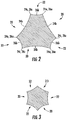
- the working portion 18 of the instrument 10 includes two or more helical flutes 20 formed along a peripheral surface of the working portion 18. As best shown in FIG. 2 , each of the flutes 20 define a curved concave flute surface when viewed in transverse cross section. Each flute 20 includes a pair of helical flute shoulders 24a and 24c at the peripheral edges of the concave flute surface. Each of the flutes 20 further include a flute base 24b defined by the point of maximum depth from the flute shoulders 24a and 24c.
- the peripheral surface of the working portion 18 of the instrument 10 further includes two or more helical lands 22 each positioned between axially adjacent flutes 20.
- each helical land 22 includes a curved concave land surface with helical land shoulders 26a and 26c at the peripheral edges of the concave land surface. As shown, each land shoulder 26a coincides with one of the flute shoulders 24a and each land shoulder. 26c coincides with one of the flute shoulders 24c. Each of the lands 22 include a land base 26b defined by the point of maximum depth between land shoulders 26a and 26c. According to preferred embodiments, the instrument 10 preferably includes three helical flutes 20 formed along the working portion 18 of the instrument 10 and three helical lands 22 disposed between axially adjacent flutes 20.
- the dimensions of the flutes 20 are greater than the dimensions of the lands 22 in at least the upper region of the working portion 18 adjacent the proximal end 14.
- the width of the helical lands 22 are smaller than the width of the flutes 20 and the land depth 26b is less than the flute depth 24b.
- the width of the lands 22 are approximately one-half to approximately three-quarters of the width of the flutes 20 in the upper region, and most preferably approximately two-thirds of the width of the flutes 20.
- the land depth 26b is approximately one-quarter to approximately one-half the flute depth 24b, and most preferably about one-third the flute depth 24b.
- the upper region of working portion 18 generally refers to the top portion adjacent the proximal end while the lower region generally refers to the lower portion adjacent the distal tip 16.
- the upper region includes roughly the top two-thirds of the working portion 18 adjacent the proximal end 14 while the lower region of the working portion 18 includes roughly the lower third of the working portion 18 adjacent the distal tip 16.
- the dimensions of lands 22 are generally the same as the dimensions of the flutes 22 in the lower region of the working portion 18.
- the flutes 20 and lands 22 of the lower region are configured to do more cutting of a canal cavity while the flutes and lands of the upper region are configured to transport debris out of the canal cavity.
- the dimensions of lands 22 gradually conform to the dimensions of the flutes 22 as one moves from the upper region to the lower region of the working portion.
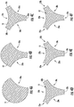
- FIGS. 4A - 4F a process for grinding the flutes 20 and lands 22 of a three-fluted and three-land instrument 10 as shown in FIGS. 1 - 3 is depicted according to one embodiment of the disclosure.
- a rotating rod 12 is moved past a grinding wheel to form a first flute 20a in the rod 12.
- the rod 12 is then indexed and again moved past the grinding wheel a second time to form second flute 20b as shown in FIG. 4B , and indexed and moved past the grinding wheel a third time to form third flute 20c as shown in FIG. 4C .
- the cutting depths and widths of the flutes 20a, 20b, 20c are controlled to leave three convex outer surfaces 30a, 30b, 30c of the original rod 12 intact between axially adjacent flutes.
- rod 12 is indexed such that the rod's fourth pass past the grinding wheel begins between axially adjacent flutes 20a, 20b to form helical land 22a in convex outer surface 30a as shown in FIG. 4D .
- Rod 12 is again indexed and moved past the grinding wheel a fifth time to form helical land 22b in convex outer surface 30b as shown in FIG. 4E and a sixth time to form helical land 22c in convex outer surface 30c as shown in FIG. 4F .
- the flutes 20 are cut into instrument 10 at a relatively shallow depth 20b using a smaller radius wheel to leave convex outer surfaces 30a, 30b, 30c with a sufficient width for forming lands 22.
- the grinding wheel has a radius of about .01 inches (0.25 mm) to about .02 inches (0.51 mm), and most preferably about .015 inches (0.381 mm), resulting in a depth 20b of flutes in the upper region of working portion 18 of about .01 inches (0.25 mm) to about .02 inches (0.51 mm), and most preferably about .015 inches (0.381mm). This compares to more traditional processes using a grinding wheel with a radius of about .01 inches (0.25 mm) to about .03 inches (0.076 mm).
- the six passes of rod 12 past the grinding wheel as described above forms an instrument with three concave flute surfaces 20 and three concave land surfaces 22 disposed between axially adjacent flutes 20.
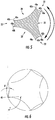
- each cutting edge 40 in the upper region of the working portion includes either a positive cutting angle ⁇ of about 75° to about 110°, and most preferably about 95° about or a negative cutting angle ⁇ of about 5° to about 35°, and most preferably about 25° depending on which direction the instrument 10 is rotated due to the flutes 20 having a greater width and depth as compared to lands 22.
- cutting edge 40 includes a positive cutting angle when the instrument 10 is rotated such that the cutting edge 40 trails flute 20 while cutting edge 40 includes a negative cutting angle when the instrument is rotated such that cutting edge 40 trails land 22.
- cutting edges 40a as shown in FIG. 5 includes three positive cutting edges and three negative cutting edges when rotated in the clockwise direction
- cutting edges 40b include three positive cutting edges and three negative cutting edges when rotated in the counterclockwise direction.
- the cutting edges with larger cutting angles make an aggressive and sharp cutting edge, which does the majority of cutting in the root canal.
- the negative cutting angles are less aggressive and will mostly clean and finish the cuts performed by the larger cutting angles.
- the negative cutting angles also provide a path for the micro cuts of debris to flow out of the root canal. Multi-directional cutting is also enhanced due to the positions of the positive and negative cutting angles in the instrument 10.
- the lower region of the working portion 18 preferably includes lands 22 with substantially the same width and depth as flutes 20. More specifically, referring back to FIG. 2 , the lower region preferably includes six cutting edges 40 each having mostly negative cutting angles of about the same size whether the instrument is rotated in the clockwise or counterclockwise direction. Thus, the lower region of the working portion 18 preferably includes all sharp cutting edges.
Description
- This disclosure relates to the field of endodontics. More particularly, this disclosure relates to instruments used for enlarging and obturating an extirpated root canal.
- In the field of endodontics, one of the most important and delicate procedures is that of cleaning or extirpating a diseased root canal to provide a properly dimensioned cavity while essentially maintaining the central axis of the canal for filling of the canal void and capping of the tooth. When done properly, this step enables substantially complete filling of the canal with biologically inert or restorative material without entrapping noxious tissue in the canal that could lead to failure of the therapy.
- In a root canal procedure, the dentist removes diseased tissue and debris from the canal prior to filling the canal with a biologically inert or restorative filling material. Many tools and techniques have been designed in an effort to enable dentists to perform the difficult task of cleaning and shaping root canals. Historically, dentists have used endodontic files to remove the soft and hard tissues in and adjacent the root canal. These endodontic files are typically made by grinding helical flutes into a working portion of a small elongate tapered rod to create a curvilinear, abrasive file with a helical cutting edge.
- Conventional endodontic instruments with helical cutting/abrading edges have certain endemic problems which, to some degree, have been tolerated and approached from a management perspective rather than an elimination perspective. For example, conventional endodontic instruments may only cut when rotated in one direction. Further, the instruments typically must be backed off after rotating in a first direction to unload the instrument before advancing the instrument further into the root canal. Conventional endodontic instruments also may begin to screw into the wall of the canal rather than continuing down the canal toward the apical tip of the root. In some cases, this "screwing in" can cause the instrument to break through the side of the root canal and into surrounding tissue or bone. Or, it may begin to "drift" or displace laterally relative to the center axis of the canal as it is moved roto-axially.
- These and other problems continue to plague practitioners and designers alike in their efforts to enlarge and prepare for filling the varied tooth root canal configurations in a manner substantially concentric with the natural or original canal curvature/shape to enable successful, effective and permanent treatment therapies. Accordingly, there is a need for improved endodontic instrument designs and methods that will avoid, minimize or eliminate drawbacks and problems associated with conventional endodontic instruments including, but not limited to, "screwing in" issues and the inability to cut in more than one direction encountered during the use of conventional endodontic instruments.
-
EP2368517A1 discloses a medical device for root canal preparation and shaping. -
WO9739696A1 - Document
EP 1 752 109 A1 shows an endodontic instrument having a plurality of helical flutes, in a cross section each flute forming a curved concave flute surface and straight land shoulders being formed between said flute concave surfaces. - The objective of the present invention is achieved by the endodontic instrument as defined in claim 1. The other claims relate to further embodiments. The above and other needs are met by an endodontic instrument adapted to be axially reciprocated within a root canal to remove material from walls of the root canal having an elongate rod having a proximate end and an opposite distal tip end defining a working portion disposed between the proximate end and the distal tip end, the working portion including an upper region and a lower region; a plurality of flutes extending helically around the working portion, each flute including a curved concave flute surface, a pair of flute shoulders at the peripheral edges of the concave flute surface, a flute width defined by a distance between the pair of flute shoulders, and a flute depth defined by a point of maximum depth between the pair of flute shoulders; and a plurality of lands extending helically around the working portion, each land positioned between a pair of axially adjacent flutes and including a curved concave land surface, a pair of land shoulders at the peripheral edges of the concave land surface, a land width defined by a distance between the pair of land shoulders, and a land depth defined by a point of maximum depth between the pair of land shoulders. Wherein the flute shoulders (24a,24c) and the land shoulders (26a,26c) consist in the peripheral edges of said curved concave flute surfaces and curved concave land surfaces respectively, and wherein each land shoulder (26a,26c) coincides with the corresponding flute shoulder (24a,24c) to form a distinct cutting edge (40). The land width is less than the flute width and the land depth is less than the flute depth in the upper region of the working portion.
- According to certain embodiments, the land width is substantially the same as the flute width and the land depth is substantially the same as the flute depth in the lower region of the working portion. In certain embodiments, the land width is approximately 1/2 to 3/4 of the flute width in the upper region of the working portion and/or the land depth is approximately 1/4 to 1/2 of the flute depth in the upper region of the working portion.
- According to certain embodiments, the plurality of flutes consists of three flutes and the plurality of lands consists of three lands.
- According to certain embodiments, the flute and land shoulders form six distinct cutting edges, each of the six distinct cutting edges including a positive cutting angle of about 75° to about 110° and a negative cutting angle of about 5° to about 30° depending on whether the instrument is rotated in a clockwise or counterclockwise direction.
- Further features, aspects, and advantages of the present disclosure will become better understood by reference to the following detailed description, appended claims, and accompanying figures, wherein elements are not to scale so as to more clearly show the details, wherein like reference numbers indicate like elements throughout the several views, and wherein:
-
FIG. 1 shows a perspective view of an endodontic instrument according to one embodiment of the disclosure; -
FIG. 2 shows a cross-sectional view of an endodontic instrument taken along lines A - A ofFIG. 1 according to one embodiment of the disclosure; -
FIG. 3 shows a cross-sectional view of an endodontic instrument taken along lines B - B ofFIG. 1 according to one embodiment of the disclosure; -
FIGS. 4A- 4F illustrates a process for forming an endodontic instrument according to one embodiment of the disclosure using cross-sectional views of the upper region of a working portion of a rod following each pass of a rod past a grinding wheel; -
FIG. 5 shows a cross-sectional view of the cutting edges in the upper region of a working portion of an endodontic instrument according to one embodiment of the disclosure; and -
FIG. 6 illustrates the cutting angles of the cutting edges ofFIG. 5 according to one embodiment of the disclosure. -
FIGS. 1 - 3 illustrate features of anendodontic instrument 10 according to one embodiment of the present disclosure. The elongate instrument is preferably formed from anelongate rod 12 of stainless steel or nickel-titanium alloy having a diameter of from about 0.3 millimeters to about 1.6 millimeters, although therod 12 may have a larger or smaller diameter and/or a varying diameter along its length as needed. In suitable embodiments,rods 12 made from other suitable metals and/or alloys may be used. In one embodiment, theinstrument 10 is formed from a controlled memory material allowing the instrument to be preformed before inserting the instrument into a root canal. - The
elongate rod 12 extends from aproximal end 14 to adistal tip end 16 of theinstrument 10. Theproximal end 14 is typically secured to a fitting portion (not shown) for mating a dental drill or hand-piece. In other embodiments, theproximal end 14 may be secured to a handle to facilitate hand manipulation of theinstrument 10. Therod 12 includes a workingportion 18 extending from adjacent thedistal tip end 16 of theinstrument 10 along the length of therod 12 to adjacent theproximal end 14. The workingportion 18 preferably has a length of from about 10 millimeters to about 20 millimeters. The diameter of the workingportion 18 of theinstrument 10 preferably tapers at a rate of from about 0.02 mm/mm to about 0.12 mm/mm, however it is also understood that the diameter of the workingportion 18 may be substantially constant along a length of the workingportion 18 and/or vary along a length of the workingportion 18. - The working
portion 18 of theinstrument 10 includes two or morehelical flutes 20 formed along a peripheral surface of the workingportion 18. As best shown inFIG. 2 , each of theflutes 20 define a curved concave flute surface when viewed in transverse cross section. Eachflute 20 includes a pair ofhelical flute shoulders flutes 20 further include aflute base 24b defined by the point of maximum depth from theflute shoulders portion 18 of theinstrument 10 further includes two or morehelical lands 22 each positioned between axiallyadjacent flutes 20. Similar toflutes 20, eachhelical land 22 includes a curved concave land surface withhelical land shoulders land shoulder 26a coincides with one of theflute shoulders 24a and each land shoulder. 26c coincides with one of theflute shoulders 24c. Each of thelands 22 include aland base 26b defined by the point of maximum depth betweenland shoulders instrument 10 preferably includes threehelical flutes 20 formed along the workingportion 18 of theinstrument 10 and threehelical lands 22 disposed between axiallyadjacent flutes 20. - Referring to
FIG. 2 , which depicts the cross section of the workingportion 18 ofinstrument 10 taken along line A-A ofFIG. 1 , the dimensions of theflutes 20 are greater than the dimensions of thelands 22 in at least the upper region of the workingportion 18 adjacent theproximal end 14. The width of thehelical lands 22 are smaller than the width of theflutes 20 and theland depth 26b is less than theflute depth 24b. According to preferred embodiments, the width of thelands 22 are approximately one-half to approximately three-quarters of the width of theflutes 20 in the upper region, and most preferably approximately two-thirds of the width of theflutes 20. According to preferred embodiments, theland depth 26b is approximately one-quarter to approximately one-half theflute depth 24b, and most preferably about one-third theflute depth 24b. For purposes of the present disclosure, the upper region of workingportion 18 generally refers to the top portion adjacent the proximal end while the lower region generally refers to the lower portion adjacent thedistal tip 16. In preferred embodiments, the upper region includes roughly the top two-thirds of the workingportion 18 adjacent theproximal end 14 while the lower region of the workingportion 18 includes roughly the lower third of the workingportion 18 adjacent thedistal tip 16. - Referring to
FIG. 3 , which depicts the cross section of the workingportion 18 ofinstrument 10 taken along line B - B ofFIG. 1 , the dimensions oflands 22 are generally the same as the dimensions of theflutes 22 in the lower region of the workingportion 18. As a result, according to preferred embodiments where the dimensions of thelands 22 are smaller than the dimensions of theflutes 20 in the upper region of the workingportion 18 and generally the same in the lower region of the workingportion 18, theflutes 20 and lands 22 of the lower region are configured to do more cutting of a canal cavity while the flutes and lands of the upper region are configured to transport debris out of the canal cavity. In preferred embodiments, the dimensions oflands 22 gradually conform to the dimensions of theflutes 22 as one moves from the upper region to the lower region of the working portion. - Referring to
FIGS. 4A - 4F , a process for grinding theflutes 20 and lands 22 of a three-fluted and three-land instrument 10 as shown inFIGS. 1 - 3 is depicted according to one embodiment of the disclosure. Referring toFIG. 4A , a rotatingrod 12 is moved past a grinding wheel to form afirst flute 20a in therod 12. Therod 12 is then indexed and again moved past the grinding wheel a second time to formsecond flute 20b as shown inFIG. 4B , and indexed and moved past the grinding wheel a third time to formthird flute 20c as shown inFIG. 4C . Referring toFIG. 4C , the cutting depths and widths of theflutes outer surfaces original rod 12 intact between axially adjacent flutes. - After forming the three
flutes rod 12 is indexed such that the rod's fourth pass past the grinding wheel begins between axiallyadjacent flutes helical land 22a in convexouter surface 30a as shown inFIG. 4D .Rod 12 is again indexed and moved past the grinding wheel a fifth time to formhelical land 22b in convexouter surface 30b as shown inFIG. 4E and a sixth time to formhelical land 22c in convexouter surface 30c as shown inFIG. 4F . - As compared to traditional processes, the
flutes 20 are cut intoinstrument 10 at a relativelyshallow depth 20b using a smaller radius wheel to leave convexouter surfaces depth 20b of flutes in the upper region of workingportion 18 of about .01 inches (0.25 mm) to about .02 inches (0.51 mm), and most preferably about .015 inches (0.381mm). This compares to more traditional processes using a grinding wheel with a radius of about .01 inches (0.25 mm) to about .03 inches (0.076 mm). - Referring to
FIG. 5 , the six passes ofrod 12 past the grinding wheel as described above forms an instrument with three concave flute surfaces 20 and threeconcave land surfaces 22 disposed between axiallyadjacent flutes 20. This results in the peripheral edges of theflutes 20 and lands 22 in the upper region of the workingportion 18 forming sixdistinct cutting edges 40a when theinstrument 10 is rotated in the clockwise direction and sixdistinct cutting edges 40b when theinstrument 10 is rotated in the counterclockwise direction. More specifically, referring to cuttingedge 40 depicted inFIG. 6 , each cuttingedge 40 in the upper region of the working portion includes either a positive cutting angle α of about 75° to about 110°, and most preferably about 95° about or a negative cutting angle β of about 5° to about 35°, and most preferably about 25° depending on which direction theinstrument 10 is rotated due to theflutes 20 having a greater width and depth as compared to lands 22. In this regard, cuttingedge 40 includes a positive cutting angle when theinstrument 10 is rotated such that thecutting edge 40trails flute 20 while cuttingedge 40 includes a negative cutting angle when the instrument is rotated such that cuttingedge 40trails land 22. Accordingly, cuttingedges 40a as shown inFIG. 5 includes three positive cutting edges and three negative cutting edges when rotated in the clockwise direction, and cuttingedges 40b include three positive cutting edges and three negative cutting edges when rotated in the counterclockwise direction. - In use, the cutting edges with larger cutting angles make an aggressive and sharp cutting edge, which does the majority of cutting in the root canal. On the other hand, the negative cutting angles are less aggressive and will mostly clean and finish the cuts performed by the larger cutting angles. The negative cutting angles also provide a path for the micro cuts of debris to flow out of the root canal. Multi-directional cutting is also enhanced due to the positions of the positive and negative cutting angles in the
instrument 10. - As noted above, the lower region of the working
portion 18 preferably includeslands 22 with substantially the same width and depth as flutes 20. More specifically, referring back toFIG. 2 , the lower region preferably includes sixcutting edges 40 each having mostly negative cutting angles of about the same size whether the instrument is rotated in the clockwise or counterclockwise direction. Thus, the lower region of the workingportion 18 preferably includes all sharp cutting edges. - The foregoing description of preferred embodiments of the present disclosure has been presented for purposes of illustration and description. The described preferred embodiments are not intended to be exhaustive or to limit the scope of the disclosure to the precise form(s) disclosed. The embodiments are chosen and described in an effort to provide the best illustrations of the principles of the disclosure and its practical application, and to thereby enable one of ordinary skill in the art to utilize the concepts revealed in the disclosure in various embodiments and with various modifications as are suited to the particular use contemplated. The scope of the present invention is defined by the appended claims.
Claims (11)
- An endodontic instrument (10) adapted to be axially reciprocated within a root canal to remove material from walls of the root canal, the endodontic instrument (10) comprising:an elongate rod (12) having a proximate end (14) and an opposite distal tip end (16) defining a working portion (18) disposed between the proximate end (14) and the distal tip end (16), the working portion (18) including an upper region and alower region;a plurality of flutes (20) extending helically around the working portion (18), each flute (20) including a curved concave flute surface, a pair of flute shoulders (24a,24c) at the peripheral edges of the concave flute surface, a flute width defined by a distance between the pair of flute shoulders (24a,24c), and a flute depth defined by a point of maximum depth between the pair of flute shoulders (24a,24c); anda plurality of lands (22) extending helically around the working portion (18), each land positioned between a pair of axially adjacent flutes (20) and including a curved concave land surface, a pair of land shoulders (26a,26c) at the peripheral edges of the concave land surface, a land width defined by a distance between the pair of land shoulders (26a,26c), and a land depth defined by a point of maximum depth between the pair of land shoulders (26a,26c),wherein the flute shoulders (24a,24c) and the land shoulders (26a,26c) consist in the peripheral edges of said curved concave flute surfaces and curved concave land surfaces respectively, andwherein each land shoulder (26a,26c) coincides with the corresponding flute shoulder (24a,24c) to form a distinct cutting edge (40).wherein the land width is less than the flute width and the land depth is less than the flute depth in the upper region of the working portion (18).
- The endodontic instrument (10) of claim 1 wherein the land width is substantially the same as the flute width and the land depth is substantially the same as the flute depth in the lower region of the working portion (18).
- The endodontic instrument (10) of claim 2 wherein the upper region of the working portion includes about two-thirds of the working portion (18) and the lower region includes about one- third of the working portion (18).
- The endodontic instrument (10) of claim 1 wherein the land width is approximately 1/2 to 3/4 of the flute width in the upper region of the working portion (18).
- The endodontic instrument (10) of claim 1 wherein the land width is approximately 2/3 of the flute width in the upper region of the working portion (18).
- The endodontic instrument (10) of claim 1 wherein the land depth is approximately 1/4 to 1/2 of the flute depth in the upper region of the working portion (18).
- The endodontic instrument (10) of claim 1 wherein the land depth is approximately 1/3 of the flute depth in the upper region of the working portion.
- The endodontic instrument (10) of claim 1 wherein the land width is approximately 1/2 to 3/4 of the flute width and the land depth is approximately 1/4 to 1/2 of the flute depth in the upper region of the working portion (18).
- The endodontic instrument (10) of claim 1 wherein the land width is approximately 2/3 of the flute width and the land depth is approximately 1/3 of the flute depth in the upper region of the working portion (18).
- The endodontic instrument (10) of claim 1 wherein the plurality of flutes (20) consists of three flutes (20) and the plurality of lands (22) consists of three lands (22).
- The endodontic instrument (10) of claim 1 wherein the flute and land shoulders (24a,24c,26a,26c) form six distinct cutting edges, each of the six distinct cutting edges including a positive cutting angle of about 75° to about 110° and a negative cutting angle of about 5° to about 30° depending on whether the instrument is rotated in a clockwise or counterclockwise direction.
Applications Claiming Priority (2)
| Application Number | Priority Date | Filing Date | Title |
|---|---|---|---|
| US15/650,045 US10130444B1 (en) | 2017-07-14 | 2017-07-14 | Endodontic instrument |
| PCT/US2018/040871 WO2019014043A1 (en) | 2017-07-14 | 2018-07-05 | Endodontic instrument |
Publications (2)
| Publication Number | Publication Date |
|---|---|
| EP3651682A1 EP3651682A1 (en) | 2020-05-20 |
| EP3651682B1 true EP3651682B1 (en) | 2021-09-22 |
Family
ID=63168472
Family Applications (1)
| Application Number | Title | Priority Date | Filing Date |
|---|---|---|---|
| EP18753266.8A Active EP3651682B1 (en) | 2017-07-14 | 2018-07-05 | Endodontic instrument |
Country Status (5)
| Country | Link |
|---|---|
| US (1) | US10130444B1 (en) |
| EP (1) | EP3651682B1 (en) |
| JP (1) | JP6915146B2 (en) |
| CA (1) | CA3067715A1 (en) |
| WO (1) | WO2019014043A1 (en) |
Families Citing this family (1)
| Publication number | Priority date | Publication date | Assignee | Title |
|---|---|---|---|---|
| PT3528739T (en) * | 2016-10-24 | 2021-08-27 | Bruder George Anthony Iii | Endodontic system and instrument for irrigation and disinfection of a tooth root canal |
Family Cites Families (13)
| Publication number | Priority date | Publication date | Assignee | Title |
|---|---|---|---|---|
| US5735689A (en) * | 1995-12-11 | 1998-04-07 | Tycom Dental Corporation | Endodontic dental instrument |
| JP3731187B2 (en) * | 1995-12-11 | 2006-01-05 | オルムコ コーポレイション | Endodontic instrument |
| DE69718161T2 (en) * | 1996-04-24 | 2003-11-13 | Ormco Corp Orange | ENDODONTIC INSTRUMENT EQUIPPED WITH A CHISEL TIP |
| JP4214285B2 (en) * | 1999-12-17 | 2009-01-28 | マニー株式会社 | Dental root canal treatment instrument and manufacturing method thereof |
| US6712611B2 (en) * | 2001-10-05 | 2004-03-30 | Ormco Corporation | Endodontic instrument with controlled flexibility and method of manufacturing same |
| US7147469B2 (en) * | 2002-08-28 | 2006-12-12 | Ormco Corporation | Endodontic instrument |
| US20040121283A1 (en) * | 2002-09-06 | 2004-06-24 | Mason Robert M. | Precision cast dental instrument |
| US20100119990A1 (en) * | 2003-01-13 | 2010-05-13 | Lampert Christopher J | Endodontic instrument and instrument system |
| JP4604140B2 (en) * | 2004-09-13 | 2010-12-22 | マニー株式会社 | Medical needle or blade |
| US7300281B2 (en) * | 2005-08-02 | 2007-11-27 | Giuseppe Cantatore | Endodontic file having bi-directional scraping edges |
| US7435086B2 (en) | 2005-08-02 | 2008-10-14 | Elio Vincenzo Giovanni Berutti | Endodontic tool having reduced torque demands |
| US7766657B2 (en) * | 2005-08-09 | 2010-08-03 | Andris Jaunberzins | Endodontic file combining active and passive cutting edges |
| EP2368517A1 (en) * | 2010-03-26 | 2011-09-28 | Michel Oiknine | Medical device for root canal preparation and shaping |
-
2017
- 2017-07-14 US US15/650,045 patent/US10130444B1/en active Active
-
2018
- 2018-07-05 JP JP2020500641A patent/JP6915146B2/en active Active
- 2018-07-05 CA CA3067715A patent/CA3067715A1/en active Pending
- 2018-07-05 EP EP18753266.8A patent/EP3651682B1/en active Active
- 2018-07-05 WO PCT/US2018/040871 patent/WO2019014043A1/en unknown
Also Published As
| Publication number | Publication date |
|---|---|
| EP3651682A1 (en) | 2020-05-20 |
| JP2020527067A (en) | 2020-09-03 |
| JP6915146B2 (en) | 2021-08-04 |
| CA3067715A1 (en) | 2019-01-17 |
| WO2019014043A1 (en) | 2019-01-17 |
| US10130444B1 (en) | 2018-11-20 |
Similar Documents
| Publication | Publication Date | Title |
|---|---|---|
| US10932884B2 (en) | Instrument for drilling dental root canals | |
| US7766657B2 (en) | Endodontic file combining active and passive cutting edges | |
| JPS59160450A (en) | Instrument for dental treatment and production thereof | |
| US8393899B2 (en) | Endodontic instrument and method | |
| JPH0510943B2 (en) | ||
| JPH01223952A (en) | Dental pulp file set equipped with safe end part | |
| US8439682B1 (en) | Set of endodontic instruments | |
| US9579166B2 (en) | Root canal probe tool and method of removing a broken instrument fragment from a root canal | |
| EP1829497B1 (en) | An endodontic file having a taper defined by a continously changing concavity | |
| EP3651682B1 (en) | Endodontic instrument | |
| US20050026109A1 (en) | Multi-tapered dental files | |
| EP2140828B1 (en) | Dental file with improved tip configuration | |
| JP2004522524A (en) | Multiple tapered dental file | |
| JP4414887B2 (en) | Dental treatment instrument with point tip and parabolic cutting groove | |
| US20150056571A1 (en) | Cross-Fluted Endodontic Instrument | |
| US20170143451A1 (en) | Cross-Fluted Endodontic Instrument | |
| JPS6142580Y2 (en) | ||
| AU2002242110A1 (en) | Multi-tapered dental files |
Legal Events
| Date | Code | Title | Description |
|---|---|---|---|
| STAA | Information on the status of an ep patent application or granted ep patent |
Free format text: STATUS: UNKNOWN |
|
| STAA | Information on the status of an ep patent application or granted ep patent |
Free format text: STATUS: THE INTERNATIONAL PUBLICATION HAS BEEN MADE |
|
| PUAI | Public reference made under article 153(3) epc to a published international application that has entered the european phase |
Free format text: ORIGINAL CODE: 0009012 |
|
| STAA | Information on the status of an ep patent application or granted ep patent |
Free format text: STATUS: REQUEST FOR EXAMINATION WAS MADE |
|
| 17P | Request for examination filed |
Effective date: 20200130 |
|
| AK | Designated contracting states |
Kind code of ref document: A1 Designated state(s): AL AT BE BG CH CY CZ DE DK EE ES FI FR GB GR HR HU IE IS IT LI LT LU LV MC MK MT NL NO PL PT RO RS SE SI SK SM TR |
|
| AX | Request for extension of the european patent |
Extension state: BA ME |
|
| DAV | Request for validation of the european patent (deleted) | ||
| DAX | Request for extension of the european patent (deleted) | ||
| STAA | Information on the status of an ep patent application or granted ep patent |
Free format text: STATUS: EXAMINATION IS IN PROGRESS |
|
| STAA | Information on the status of an ep patent application or granted ep patent |
Free format text: STATUS: EXAMINATION IS IN PROGRESS |
|
| 17Q | First examination report despatched |
Effective date: 20210118 |
|
| REG | Reference to a national code |
Ref country code: DE Ref legal event code: R079 Ref document number: 602018023959 Country of ref document: DE Free format text: PREVIOUS MAIN CLASS: A61C0005420000 Ipc: B23B0031110000 |
|
| GRAP | Despatch of communication of intention to grant a patent |
Free format text: ORIGINAL CODE: EPIDOSNIGR1 |
|
| STAA | Information on the status of an ep patent application or granted ep patent |
Free format text: STATUS: GRANT OF PATENT IS INTENDED |
|
| RIC1 | Information provided on ipc code assigned before grant |
Ipc: B23B 31/107 20060101ALI20210416BHEP Ipc: B23B 31/11 20060101AFI20210416BHEP |
|
| INTG | Intention to grant announced |
Effective date: 20210510 |
|
| GRAS | Grant fee paid |
Free format text: ORIGINAL CODE: EPIDOSNIGR3 |
|
| GRAA | (expected) grant |
Free format text: ORIGINAL CODE: 0009210 |
|
| STAA | Information on the status of an ep patent application or granted ep patent |
Free format text: STATUS: THE PATENT HAS BEEN GRANTED |
|
| AK | Designated contracting states |
Kind code of ref document: B1 Designated state(s): AL AT BE BG CH CY CZ DE DK EE ES FI FR GB GR HR HU IE IS IT LI LT LU LV MC MK MT NL NO PL PT RO RS SE SI SK SM TR |
|
| REG | Reference to a national code |
Ref country code: GB Ref legal event code: FG4D |
|
| REG | Reference to a national code |
Ref country code: IE Ref legal event code: FG4D |
|
| REG | Reference to a national code |
Ref country code: DE Ref legal event code: R096 Ref document number: 602018023959 Country of ref document: DE |
|
| REG | Reference to a national code |
Ref country code: CH Ref legal event code: EP Ref country code: AT Ref legal event code: REF Ref document number: 1431922 Country of ref document: AT Kind code of ref document: T Effective date: 20211015 |
|
| REG | Reference to a national code |
Ref country code: SE Ref legal event code: TRGR |
|
| REG | Reference to a national code |
Ref country code: LT Ref legal event code: MG9D |
|
| REG | Reference to a national code |
Ref country code: NL Ref legal event code: MP Effective date: 20210922 |
|
| PG25 | Lapsed in a contracting state [announced via postgrant information from national office to epo] |
Ref country code: BG Free format text: LAPSE BECAUSE OF FAILURE TO SUBMIT A TRANSLATION OF THE DESCRIPTION OR TO PAY THE FEE WITHIN THE PRESCRIBED TIME-LIMIT Effective date: 20211222 Ref country code: LT Free format text: LAPSE BECAUSE OF FAILURE TO SUBMIT A TRANSLATION OF THE DESCRIPTION OR TO PAY THE FEE WITHIN THE PRESCRIBED TIME-LIMIT Effective date: 20210922 Ref country code: NO Free format text: LAPSE BECAUSE OF FAILURE TO SUBMIT A TRANSLATION OF THE DESCRIPTION OR TO PAY THE FEE WITHIN THE PRESCRIBED TIME-LIMIT Effective date: 20211222 Ref country code: FI Free format text: LAPSE BECAUSE OF FAILURE TO SUBMIT A TRANSLATION OF THE DESCRIPTION OR TO PAY THE FEE WITHIN THE PRESCRIBED TIME-LIMIT Effective date: 20210922 Ref country code: HR Free format text: LAPSE BECAUSE OF FAILURE TO SUBMIT A TRANSLATION OF THE DESCRIPTION OR TO PAY THE FEE WITHIN THE PRESCRIBED TIME-LIMIT Effective date: 20210922 Ref country code: RS Free format text: LAPSE BECAUSE OF FAILURE TO SUBMIT A TRANSLATION OF THE DESCRIPTION OR TO PAY THE FEE WITHIN THE PRESCRIBED TIME-LIMIT Effective date: 20210922 |
|
| REG | Reference to a national code |
Ref country code: AT Ref legal event code: MK05 Ref document number: 1431922 Country of ref document: AT Kind code of ref document: T Effective date: 20210922 |
|
| PG25 | Lapsed in a contracting state [announced via postgrant information from national office to epo] |
Ref country code: LV Free format text: LAPSE BECAUSE OF FAILURE TO SUBMIT A TRANSLATION OF THE DESCRIPTION OR TO PAY THE FEE WITHIN THE PRESCRIBED TIME-LIMIT Effective date: 20210922 Ref country code: GR Free format text: LAPSE BECAUSE OF FAILURE TO SUBMIT A TRANSLATION OF THE DESCRIPTION OR TO PAY THE FEE WITHIN THE PRESCRIBED TIME-LIMIT Effective date: 20211223 |
|
| PG25 | Lapsed in a contracting state [announced via postgrant information from national office to epo] |
Ref country code: AT Free format text: LAPSE BECAUSE OF FAILURE TO SUBMIT A TRANSLATION OF THE DESCRIPTION OR TO PAY THE FEE WITHIN THE PRESCRIBED TIME-LIMIT Effective date: 20210922 |
|
| PG25 | Lapsed in a contracting state [announced via postgrant information from national office to epo] |
Ref country code: IS Free format text: LAPSE BECAUSE OF FAILURE TO SUBMIT A TRANSLATION OF THE DESCRIPTION OR TO PAY THE FEE WITHIN THE PRESCRIBED TIME-LIMIT Effective date: 20220122 Ref country code: SK Free format text: LAPSE BECAUSE OF FAILURE TO SUBMIT A TRANSLATION OF THE DESCRIPTION OR TO PAY THE FEE WITHIN THE PRESCRIBED TIME-LIMIT Effective date: 20210922 Ref country code: RO Free format text: LAPSE BECAUSE OF FAILURE TO SUBMIT A TRANSLATION OF THE DESCRIPTION OR TO PAY THE FEE WITHIN THE PRESCRIBED TIME-LIMIT Effective date: 20210922 Ref country code: PT Free format text: LAPSE BECAUSE OF FAILURE TO SUBMIT A TRANSLATION OF THE DESCRIPTION OR TO PAY THE FEE WITHIN THE PRESCRIBED TIME-LIMIT Effective date: 20220124 Ref country code: PL Free format text: LAPSE BECAUSE OF FAILURE TO SUBMIT A TRANSLATION OF THE DESCRIPTION OR TO PAY THE FEE WITHIN THE PRESCRIBED TIME-LIMIT Effective date: 20210922 Ref country code: NL Free format text: LAPSE BECAUSE OF FAILURE TO SUBMIT A TRANSLATION OF THE DESCRIPTION OR TO PAY THE FEE WITHIN THE PRESCRIBED TIME-LIMIT Effective date: 20210922 Ref country code: ES Free format text: LAPSE BECAUSE OF FAILURE TO SUBMIT A TRANSLATION OF THE DESCRIPTION OR TO PAY THE FEE WITHIN THE PRESCRIBED TIME-LIMIT Effective date: 20210922 Ref country code: EE Free format text: LAPSE BECAUSE OF FAILURE TO SUBMIT A TRANSLATION OF THE DESCRIPTION OR TO PAY THE FEE WITHIN THE PRESCRIBED TIME-LIMIT Effective date: 20210922 Ref country code: CZ Free format text: LAPSE BECAUSE OF FAILURE TO SUBMIT A TRANSLATION OF THE DESCRIPTION OR TO PAY THE FEE WITHIN THE PRESCRIBED TIME-LIMIT Effective date: 20210922 Ref country code: AL Free format text: LAPSE BECAUSE OF FAILURE TO SUBMIT A TRANSLATION OF THE DESCRIPTION OR TO PAY THE FEE WITHIN THE PRESCRIBED TIME-LIMIT Effective date: 20210922 |
|
| REG | Reference to a national code |
Ref country code: DE Ref legal event code: R097 Ref document number: 602018023959 Country of ref document: DE |
|
| PG25 | Lapsed in a contracting state [announced via postgrant information from national office to epo] |
Ref country code: DK Free format text: LAPSE BECAUSE OF FAILURE TO SUBMIT A TRANSLATION OF THE DESCRIPTION OR TO PAY THE FEE WITHIN THE PRESCRIBED TIME-LIMIT Effective date: 20210922 |
|
| PLBE | No opposition filed within time limit |
Free format text: ORIGINAL CODE: 0009261 |
|
| STAA | Information on the status of an ep patent application or granted ep patent |
Free format text: STATUS: NO OPPOSITION FILED WITHIN TIME LIMIT |
|
| 26N | No opposition filed |
Effective date: 20220623 |
|
| PG25 | Lapsed in a contracting state [announced via postgrant information from national office to epo] |
Ref country code: SI Free format text: LAPSE BECAUSE OF FAILURE TO SUBMIT A TRANSLATION OF THE DESCRIPTION OR TO PAY THE FEE WITHIN THE PRESCRIBED TIME-LIMIT Effective date: 20210922 |
|
| PG25 | Lapsed in a contracting state [announced via postgrant information from national office to epo] |
Ref country code: MC Free format text: LAPSE BECAUSE OF FAILURE TO SUBMIT A TRANSLATION OF THE DESCRIPTION OR TO PAY THE FEE WITHIN THE PRESCRIBED TIME-LIMIT Effective date: 20210922 |
|
| REG | Reference to a national code |
Ref country code: BE Ref legal event code: MM Effective date: 20220731 |
|
| PG25 | Lapsed in a contracting state [announced via postgrant information from national office to epo] |
Ref country code: LU Free format text: LAPSE BECAUSE OF NON-PAYMENT OF DUE FEES Effective date: 20220705 |
|
| PG25 | Lapsed in a contracting state [announced via postgrant information from national office to epo] |
Ref country code: BE Free format text: LAPSE BECAUSE OF NON-PAYMENT OF DUE FEES Effective date: 20220731 |
|
| PG25 | Lapsed in a contracting state [announced via postgrant information from national office to epo] |
Ref country code: IE Free format text: LAPSE BECAUSE OF NON-PAYMENT OF DUE FEES Effective date: 20220705 |
|
| PGFP | Annual fee paid to national office [announced via postgrant information from national office to epo] |
Ref country code: IT Payment date: 20230612 Year of fee payment: 6 Ref country code: FR Payment date: 20230620 Year of fee payment: 6 |
|
| PGFP | Annual fee paid to national office [announced via postgrant information from national office to epo] |
Ref country code: SE Payment date: 20230613 Year of fee payment: 6 |
|
| PGFP | Annual fee paid to national office [announced via postgrant information from national office to epo] |
Ref country code: GB Payment date: 20230601 Year of fee payment: 6 Ref country code: CH Payment date: 20230801 Year of fee payment: 6 |
|
| PGFP | Annual fee paid to national office [announced via postgrant information from national office to epo] |
Ref country code: DE Payment date: 20230531 Year of fee payment: 6 |