EP3651480A1 - Signalverarbeitungsvorrichtung und -verfahren und programm - Google Patents
Signalverarbeitungsvorrichtung und -verfahren und programm Download PDFInfo
- Publication number
- EP3651480A1 EP3651480A1 EP18828168.7A EP18828168A EP3651480A1 EP 3651480 A1 EP3651480 A1 EP 3651480A1 EP 18828168 A EP18828168 A EP 18828168A EP 3651480 A1 EP3651480 A1 EP 3651480A1
- Authority
- EP
- European Patent Office
- Prior art keywords
- rotation
- head
- matrix
- rotation matrix
- angle
- Prior art date
- Legal status (The legal status is an assumption and is not a legal conclusion. Google has not performed a legal analysis and makes no representation as to the accuracy of the status listed.)
- Withdrawn
Links
Images


Classifications
-
- H—ELECTRICITY
- H04—ELECTRIC COMMUNICATION TECHNIQUE
- H04S—STEREOPHONIC SYSTEMS
- H04S7/00—Indicating arrangements; Control arrangements, e.g. balance control
- H04S7/30—Control circuits for electronic adaptation of the sound field
- H04S7/302—Electronic adaptation of stereophonic sound system to listener position or orientation
- H04S7/303—Tracking of listener position or orientation
- H04S7/304—For headphones
-
- H—ELECTRICITY
- H04—ELECTRIC COMMUNICATION TECHNIQUE
- H04S—STEREOPHONIC SYSTEMS
- H04S3/00—Systems employing more than two channels, e.g. quadraphonic
- H04S3/02—Systems employing more than two channels, e.g. quadraphonic of the matrix type, i.e. in which input signals are combined algebraically, e.g. after having been phase shifted with respect to each other
-
- H—ELECTRICITY
- H04—ELECTRIC COMMUNICATION TECHNIQUE
- H04R—LOUDSPEAKERS, MICROPHONES, GRAMOPHONE PICK-UPS OR LIKE ACOUSTIC ELECTROMECHANICAL TRANSDUCERS; DEAF-AID SETS; PUBLIC ADDRESS SYSTEMS
- H04R2400/00—Loudspeakers
- H04R2400/01—Transducers used as a loudspeaker to generate sound aswell as a microphone to detect sound
-
- H—ELECTRICITY
- H04—ELECTRIC COMMUNICATION TECHNIQUE
- H04R—LOUDSPEAKERS, MICROPHONES, GRAMOPHONE PICK-UPS OR LIKE ACOUSTIC ELECTROMECHANICAL TRANSDUCERS; DEAF-AID SETS; PUBLIC ADDRESS SYSTEMS
- H04R5/00—Stereophonic arrangements
- H04R5/033—Headphones for stereophonic communication
-
- H—ELECTRICITY
- H04—ELECTRIC COMMUNICATION TECHNIQUE
- H04S—STEREOPHONIC SYSTEMS
- H04S2400/00—Details of stereophonic systems covered by H04S but not provided for in its groups
- H04S2400/01—Multi-channel, i.e. more than two input channels, sound reproduction with two speakers wherein the multi-channel information is substantially preserved
-
- H—ELECTRICITY
- H04—ELECTRIC COMMUNICATION TECHNIQUE
- H04S—STEREOPHONIC SYSTEMS
- H04S2420/00—Techniques used stereophonic systems covered by H04S but not provided for in its groups
- H04S2420/01—Enhancing the perception of the sound image or of the spatial distribution using head related transfer functions [HRTF's] or equivalents thereof, e.g. interaural time difference [ITD] or interaural level difference [ILD]
-
- H—ELECTRICITY
- H04—ELECTRIC COMMUNICATION TECHNIQUE
- H04S—STEREOPHONIC SYSTEMS
- H04S2420/00—Techniques used stereophonic systems covered by H04S but not provided for in its groups
- H04S2420/11—Application of ambisonics in stereophonic audio systems
Definitions
- the present technology relates to signal processing device and method, and a program, and specifically to signal processing device and method, and a program that make it possible to reproduce sound more efficiently.
- ambisonics there is a technique of representing three-dimensional audio information, which is flexibly adaptable to any recording/reproducing system.
- the technique is called ambisonics, and has been attracting attention.
- second or higher order ambisonics is called higher order ambisonics (HOA) (see NPTL 1, for example).
- spherical harmonic function transformation corresponds to time-frequency transformation of an audio signal with respect to a time axis.
- Advantages of this method include ability to encode and decode information from any microphone array to any speaker array without limiting the number of microphones or the number of speakers.
- impediments to spread of ambisonics include need for a speaker array including a large number of speakers in a reproduction environment, and a narrow range (sweet spot) where it is possible to reproduce sound space.
- a speaker array including more speakers is necessary to increase spatial resolution of sound, but it is impractical to increase such a system at home or the like.
- a region where it is possible to reproduce sound space is narrow, and it is difficult to give desired effects to an entire audience.
- NPTL 1 Jerome Daniel, Rozenn Nicol, Sebastien Moreau, "Further Investigations of High Order Ambisonics and Wavefield Synthesis for Holophonic Sound Imaging," AES 114th Convention, Amsterdam, Netherlands, 2003 .
- the binaural reproduction technology is generally called virtual auditory display (VAD), and is implemented using a head-related transfer function (HRTF).
- VAD virtual auditory display
- HRTF head-related transfer function
- the head-related transfer function expresses information regarding how sound is transmitted from every direction surrounding a human head to binaural eardrums as a function of frequency and arrival direction.
- the VAD is a system that utilizes such a principle.
- the present technology has been made in light of such a situation, and makes it possible to reproduce sound more efficiently.
- a signal processing device includes: a rotation operation unit that rotates a head-related transfer function in a spherical harmonic domain by an operation on the basis of a rotation matrix corresponding to rotation of a head of a listener, the operation in which an order of the rotation matrix is limited; and a synthesis unit that synthesizes the head-related transfer function after rotation obtained by the operation and a sound signal of the spherical harmonic domain to generate a headphone drive signal.
- a signal processing method or a program includes steps of: rotating a head-related transfer function in a spherical harmonic domain by an operation on the basis of a rotation matrix corresponding to rotation of a head of a listener, the operation in which an order of the rotation matrix is limited; and synthesizing the head-related transfer function after rotation obtained by the operation and a sound signal of the spherical harmonic domain to generate a headphone drive signal.
- the head-related transfer function in the spherical harmonic domain is rotated by the operation in which the order of the rotation matrix is limited on the basis of the rotation matrix corresponding to the rotation of the head of the listener, and the head-related transfer function after the rotation obtained by the operation and the sound signal of the spherical harmonic domain are synthesized to generate the headphone drive signal.
- the present technology achieves a reproduction system that is more efficient in an operation amount and a memory usage amount by determining a head-related transfer function in a spherical harmonic domain corresponding to rotation of a head with use of accumulation of minute rotations and synthesizing, in the spherical harmonic domain, the head-related transfer function and an input signal of sound to be reproduced.
- spherical harmonic function transformation on a function f( ⁇ , ⁇ ) on spherical coordinates is expressed by the following expression (1).
- F n m ⁇ 0 2 ⁇ ⁇ ⁇ 0 ⁇ f ⁇ ⁇ Y n m ⁇ ⁇ ⁇ sin ⁇ ⁇ ⁇ d ⁇ ⁇ ⁇ d ⁇ ⁇ ⁇ d ⁇ ⁇
- ⁇ and ⁇ respectively represent an elevation angle and a horizontal angle in the spherical coordinates
- Y n m ( ⁇ , ⁇ ) represents a spherical harmonic function
- the spherical harmonic function Y n m ( ⁇ , ⁇ ) with "-" at a top thereof represents a complex conjugate of the spherical harmonic function Y n m ( ⁇ , ⁇ ).
- Y n m ( ⁇ , ⁇ ) is expressed by the following expression (2).
- Y n m ⁇ ⁇ ⁇ 1 m 2 n + 1 n ⁇ m ! 4 ⁇ ⁇ n + m ! P n m cos ⁇ e im ⁇ ⁇
- n and m represent a degree and an order of the spherical harmonic function Y n m ( ⁇ , ⁇ ), and are -n ⁇ m ⁇ n.
- the order m is also referred to as order or period, and hereinafter, in a case where it is not necessary to particularly distinguish n and m, the degree n and the order m are collectively referred to as degrees.
- i represents a pure imaginary number
- P n m (x) represents an associated Legendre function
- P n 0 x 1 2 n n ! d n dx n x 2 ⁇ 1 n
- P n m x 1 ⁇ x 2 m / 2 d n dx n P m 0 x
- x i represents a position of the speaker
- ⁇ represents a time frequency of a sound signal.
- the input signal D' n m ( ⁇ ) is a sound signal corresponding to each degree n and each order m of the spherical harmonic function for a predetermined time frequency ⁇ .
- x i (Rsin ⁇ i cos ⁇ i , Rsin ⁇ i sin ⁇ i , Rcos ⁇ i ), and i represents a speaker index that specifies the speaker.
- i 1, 2, ..., L, and ⁇ i and ⁇ i respectively represent an elevation angle and a horizontal angle that indicate a position of the i-th speaker.
- Such transformation expressed by the expression (7) is spherical harmonic inverse transformation corresponding to the expression (6).
- the L number of speakers is the number of reproducing speakers. [Math. 8] L > N + 1 2
- a general technique of simulating stereophony at ears by representation with headphones is, for example, a method using the head-related transfer function as illustrated in FIG. 1 .
- an inputted ambisonics signal is decoded to generate a speaker drive signal of each of virtual speakers SP11-1 to SP11-8, which are a plurality of virtual speakers.
- the signal decoded at this time corresponds to, for example, the input signal D' n m ( ⁇ ) described above.
- each of the virtual speakers SP11-1 to virtual speakers SP11-8 is annularly disposed and virtually arranged, and the speaker drive signal of each of the virtual speakers is determined by the calculation of the expression (7) described above. It is to be noted that the virtual speakers are also simply referred to as virtual speakers SP11 hereinafter in a case where it is not necessary to particularly distinguish the virtual speakers SP11-1 to SP11-8.
- left and right drive signals (binaural signals) of headphones HD11 that actually reproduce sound are generated by a convolution operation using the head-related transfer function. Then, the sum of the respective drive signals of the headphones HD11 obtained for each of the virtual speakers SP11 is a final drive signal.
- the head-related transfer function H(x, ⁇ ) is convolved with an optional audio signal, and a thus-obtained result is presented with headphones or the like, which makes it possible to give, to the listener, an illusion as if sound comes from a direction of the convolved head-related transfer function H(x, ⁇ ), that is, a direction of the sound source position x.
- the left and right drive signals of the headphones HD11 are generated with use of such a principle.
- the position of each of the virtual speakers SP11 is set as the position x i , and the speaker drive signals of these virtual speakers SP11 are set as S(x i , ⁇ ).
- H l (x i , ⁇ ) and H r (x i , ⁇ ) represent normalized head-related transfer functions from the position x i of the virtual speaker SP11 to left and right eardrum positions of the listener, respectively.
- Such an operation makes it possible to finally reproduce the input signal D' n m ( ⁇ ) of the spherical harmonic domain by presentation with the headphones. That is, it is possible to achieve the same effects as those of ambisonics by presentation with the headphones.
- the drive signal P l and the drive signal P r are also simply referred to as drive signals P( ⁇ ).
- the head-related transfer function H l (x i , ⁇ ) and the head-related transfer function H r (x i , ⁇ ) are also simply referred to as head-related transfer functions H(x i , ⁇ ).
- first technique the technique of combining ambisonics and binaural reproduction technology described above is also referred to as first technique.
- an operation illustrated in FIG. 2 is performed to obtain the drive signal P( ⁇ ) of 1 ⁇ 1, that is, one row and one column.
- H( ⁇ ) represents a vector (matrix) of 1 ⁇ L including the L number of head-related transfer functions H(x i , ⁇ ).
- D'( ⁇ ) represents a vector including the input signal D' n m ( ⁇ ), and the vector D'( ⁇ ) becomes K ⁇ 1, where the number of input signals D' n m ( ⁇ ) of bins of the same time frequency ⁇ is K.
- Y(x) represents a matrix including the spherical harmonic function Y n m ( ⁇ i , ⁇ i ) of each degree, and the matrix Y(x) becomes a matrix of L ⁇ K.
- a matrix (vector) S obtained from a matrix operation of the matrix Y(x) of L ⁇ K and the vector D'( ⁇ ) of K ⁇ 1 is determined, and a matrix operation of the matrix S and the vector (matrix) H( ⁇ ) of 1 ⁇ L is further performed to obtain one drive signal P( ⁇ ).
- the drive signal P l (g j , ⁇ ) of a left headphone of the headphones HD11 is as expressed in the following expression (11).
- the rotation matrix g j is a three-dimensional, i.e., 3 ⁇ 3 rotation matrix represented by ⁇ , ⁇ , and ⁇ that are rotational angles of Euler angles.
- the drive signal P l (g j , ⁇ ) represents the drive signal P l described above, and is written as the drive signal P l (g j , ⁇ ) herein to clarify the position, that is, the direction g j and the time frequency ⁇ .
- the rotation direction of the head of the listener that is, the direction g j of the head of the listener may be obtained by some sensor, and left and right drive signals of the headphones HD11 may be calculated using the head-related transfer function of a relative direction g j -1 x i of each of the virtual speakers SP11 viewed from the head of the listener from among a plurality of head-related transfer functions.
- convolution of the head-related transfer function performed in the time frequency domain may be performed in a spherical harmonic domain. Doing so makes it possible to reduce the operation amount and the necessary memory amount as compared with the first technique, and to reproduce sound more efficiently.
- Such a technique of convoluting the head-related transfer function in the spherical harmonic domain is also referred to as second technique, and the second technique is described below.
- the vector P l ( ⁇ ) including each of the drive signals P l (g j , ⁇ ) of the left headphone for all rotation directions of the head of the user (listener), who is a listener is expressed by the following expression (12).
- Y(x) represents a matrix including each degree and the spherical harmonic function Y n m (x i ) of the position x i of each of the virtual speakers expressed by the following expression (13).
- i 1, 2, ..., L, and a maximum value (maximum degree) of the degree n is N.
- D'( ⁇ ) represents a vector (matrix) including the input signal D' n m ( ⁇ ) of sound corresponding to each degree, which is expressed by the following expression (14).
- Each input signal D' n m ( ⁇ ) is a sound signal of the spherical harmonic domain.
- H( ⁇ ) represents a matrix, as expressed by the following expression (15), including the head-related transfer function H(g j -1 x i , ⁇ ) of the relative direction g j -1 x i of each of the virtual speakers viewed from the head of the listener in a case where the direction of the head of the listener is the direction g j .
- the head-related transfer function H(g j -1 x i , ⁇ ) of each of the virtual speakers is prepared for each of the total M number of directions g 1 to g M . [Math.
- the head-related transfer function is prepared for each of the M number of directions; therefore, matrix calculation expressed by the expression (12) is as indicated by an arrow A11.
- the vector D'( ⁇ ) is K ⁇ 1, that is, a matrix of K rows and one column.
- the matrix Y(x) of the spherical harmonic function is L ⁇ K
- the matrix H( ⁇ ) is M ⁇ L. Accordingly, in the calculation of the expression (12), the vector P l ( ⁇ ) is M ⁇ 1.
- a matrix operation (product-sum operation) of the matrix Y(x) and the vector D'( ⁇ ) is first performed in an online operation to determine the vector S( ⁇ ), which makes it possible to select a row corresponding to the direction g j of the head of the listener in the matrix H( ⁇ ) as indicated by the arrow A12 and reduce the operation amount at the time of calculation of the drive signal P l (g j , ⁇ ).
- a hatched portion in the matrix H( ⁇ ) represents the row corresponding to the direction g j , and an operation of this row and the vector S( ⁇ ) is performed to calculate the desired drive signal P l (g j , ⁇ ) of the left headphone.
- the matrix H'( ⁇ ) is defined as expressed by the following expression (16), which makes it possible to express, by the following expression (17), the vector P l ( ⁇ ) expressed by the expression (12).
- H ′ ⁇ H ⁇ Y x
- P l ⁇ H ′ ⁇ D ′ ⁇
- the head-related transfer function more specifically, the matrix H( ⁇ ) including the head-related transfer function in the time-frequency domain, is transformed by the spherical harmonic function transformation using the spherical harmonic function into the matrix H'( ⁇ ) including the head-related transfer function in the spherical harmonic domain.
- H' n m (g j , ⁇ ) is one element of the matrix H'( ⁇ ), that is, a head-related transfer function in the spherical harmonic domain, which is a component (element) corresponding to the direction g j of the head in the matrix H'( ⁇ ).
- H' n m (g j , ⁇ ) n and m represent the degree n and the order m of the spherical harmonic function.
- calculation expressed by the expression (12) is calculation to determine a product of the matrix H( ⁇ ) of M ⁇ L, the matrix Y(x) of L ⁇ K, and the vector D'( ⁇ ) of K ⁇ 1 as indicated by an arrow A21 in FIG. 4 .
- H( ⁇ )Y(x) is the matrix H'( ⁇ ) as defined in the expression (16); therefore, the calculation indicated by the arrow A21 eventually becomes as indicated by an arrow A22.
- the row corresponding to the direction g j of the head of the listener in the matrix H'( ⁇ ) is selected, and the drive signal P l (g j , ⁇ ) of the left headphone is calculated by a matrix operation of that selected row and the vector D'( ⁇ ) including the inputted input signal D' n m ( ⁇ ).
- a hatched portion in the matrix H'( ⁇ ) represents the row corresponding to the direction g j , and an element included in this row is the head-related transfer function H' n m (g j , ⁇ ) expressed by the expression (18).
- third technique such a technique is referred to as third technique.
- the rotation matrix R'(g j ) of each of the directions g j is different from the matrix H'( ⁇ ) and has no time frequency dependence. This makes it possible to greatly reduce the memory amount as compared with making the matrix H'( ⁇ ) hold the component of the direction g j of rotation of the head.
- R' (n) k,m (g j ) is expressed by the following expression (24).
- R ′ k , m n g j e ⁇ im ⁇ ⁇ r k , m n ⁇ e ⁇ ik ⁇ ⁇
- i a pure imaginary number
- ⁇ , ⁇ , and ⁇ rotational angles of Euler angles of the rotation matrix
- r (n) k,m ( ⁇ ) is expressed by the following expression (25).
- r k , m n ⁇ n + k ! n ⁇ k ! n + m ! n ⁇ m ! ⁇ ⁇ n + m n ⁇ k ⁇ ⁇ n ⁇ ⁇ 1 n ⁇ k ⁇ ⁇ cos ⁇ 2 2 ⁇ ⁇ + k + m sin ⁇ 2 2 ⁇ n ⁇ ⁇ 2 ⁇ ⁇ k ⁇ m
- a binaural reproducing signal reflecting the rotation of the head of the listener by using the rotation matrix R'(g j -1 ), for example, the drive signal P l (g j , ⁇ ) of the left headphone is obtained by calculating the following expression (26).
- performing inversion is performed using a matrix R ref that makes either the matrix D'( ⁇ ) of the input signal or the row vector H S ( ⁇ ) of a left head-related transfer function horizontally flip as pre-processing of the expression (26), which makes it possible to obtain a right headphone drive signal only by holding the row vector H S ( ⁇ ) of the left head-related transfer function.
- the drive signal P l (g j , ⁇ ) is determined by synthesizing the row vector H S ( ⁇ ), the rotation matrix R'(g j -1 ), and the vector D'( ⁇ ).
- the calculation as described above is, for example, calculation illustrated in FIG. 5 . That is, the vector P l ( ⁇ ) including the drive signal P l (g j , ⁇ ) of the left headphone is obtained by the product of the matrix H( ⁇ ) of M ⁇ L, the matrix Y(x) of L ⁇ K, and the vector D'( ⁇ ) of K ⁇ 1, as indicated by an arrow A41 in FIG. 5 .
- This matrix operation is as expressed by the expression (12) described above.
- This operation is represented by using the matrix Y(g j x) of the spherical harmonic function prepared for each of M number of directions g j , as indicated by an arrow A42. That is, the vector P l ( ⁇ ) including the drive signal P l (g j , ⁇ ) corresponding to each of the M number of directions g j is obtained by the product of the predetermined row H(x, ⁇ ) of the matrix H( ⁇ ), the matrix Y(g j x), and the vector D'( ⁇ ) from a relationship expressed by the expression (20).
- the row H(x, ⁇ ), which is a vector, is 1 ⁇ L
- the matrix Y(g j x) is L ⁇ K
- the vector D'( ⁇ ) is K ⁇ 1.
- the vector P l ( ⁇ ) is obtained by the product of the row vector H S ( ⁇ ) of 1 ⁇ K
- hatched portions of the rotation matrix R'(g j -1 ) represent non-zero elements of the rotation matrix R'(g j -1 ).
- FIG. 6 illustrates the operation amount and the necessary memory amount in such a third technique.
- the row vector H S ( ⁇ ) of 1 ⁇ K is prepared for each time frequency bin ⁇
- the rotation matrix R'(g j -1 ) of K ⁇ K is prepared for the M number of directions g j
- the vector D'( ⁇ ) is K ⁇ 1.
- the number of time frequency bins ⁇ is W
- the maximum value of the degree n of the spherical harmonic function, that is, the maximum degree is J.
- the rotation matrix R'(g j -1 ) for performing rotation about the head of the listener as a rotation center in the spherical harmonic domain may be sequentially determined at the time of an operation.
- such a technique is also referred to as fourth technique.
- a rotation matrix R'(g) by the following expression (29).
- g in the expression (29) is a rotation matrix, and is represented by the product of a matrix u( ⁇ ), a matrix a( ⁇ ), and a matrix u( ⁇ ) as expressed by the following expression (30).
- g u ⁇ a ⁇ u ⁇
- a( ⁇ ) and u( ⁇ ) are rotation matrices that rotate coordinates by an angle ⁇ and an angle ⁇ about a coordinate axis as a rotation axis of a coordinate system in which the position of the head of the lister is an origin point.
- u( ⁇ ) is a rotation matrix that is only different in the rotation angle from u( ⁇ ) and rotates the coordinates by an angle ⁇ about the same coordinate axis as the rotation axis.
- rotation angles of the respective matrices u( ⁇ ), a( ⁇ ), and u( ⁇ ), that is, the angle ⁇ , the angle ⁇ , and the angle ⁇ are Euler angles.
- a positive direction of the x axis is a direction of the front
- the z axis is an upward-downward direction viewed from the listener directed to the front, that is, an axis in a vertical direction.
- the angle ⁇ , the angle ⁇ , and the angle ⁇ are rotation angles to respective rotation directions relative to the state in which the listener is directed to the front, that is, to the positive direction of the x axis.
- the rotation angle of the head in a case where the head moves in the upward-downward direction about the y axis as the rotation axis while the listener seeing the front is the angle ⁇ that is an elevation angle.
- the rotation angle of the head in a case where the head moves in a horizontal direction viewed from the listener about the z axis as the rotation axis while the listener is directed to the front is the angle ⁇ that is a horizontal angle.
- the matrix a( ⁇ ) is a rotation matrix that rotates the coordinates (coordinate system) by the angle ⁇ about the y axis as the rotation axis
- the matrix u( ⁇ ) is a rotation matrix that rotates the coordinates (coordinate system) by the angle ⁇ about the z axis as the rotation axis.
- these matrices a( ⁇ ) and u( ⁇ ) are as expressed by the following expressions (31) and (32), respectively.
- a position v 2 after the rotation of the position v is expressed by the following expression (33).
- R'(u( ⁇ )), R'(a( ⁇ )), and R'(u( ⁇ )) represent the rotation matrices R'(g) in a case where the coordinates are rotated by rotations by the matrix (u( ⁇ )), the matrix (a( ⁇ )), and the matrix (u( ⁇ )), respectively.
- the rotation matrix R'(u( ⁇ )) is a rotation matrix that rotates the coordinates by the angle ⁇ in the horizontal angle direction in the spherical harmonic domain
- the rotation matrix R'(a( ⁇ )) is a rotation matrix that rotates the coordinates by the angle ⁇ in the elevation angle direction in the spherical harmonic domain
- the rotation matrix R'(u( ⁇ )) is a rotation matrix that rotates the coordinates by the angle ⁇ in the horizontal angle direction in the spherical harmonic domain.
- the rotation matrix R'(g j -1 ) As data for obtaining the rotation matrix R'(g j -1 ), the rotation matrix R'(u( ⁇ )), the rotation matrix R'(a( ⁇ )), and the rotation matrix R'(u( ⁇ )) for the respective values of the rotation angles ⁇ , ⁇ , and ⁇ are held in tables in the memory.
- the row vector H S ( ⁇ ) is held for only one ear, and the matrix Rref described above for horizontal inversion is also held in advance, which makes it possible to obtain the rotation matrix for the other ear by determining the product of this and a generated rotation matrix.
- one rotation matrix R'(g j -1 ) is calculated by calculating the product of respective rotation matrices read out from tables. Then, as indicated by an arrow A52, the product of the matrix H S ( ⁇ ) of 1 ⁇ K, the rotation matrix R'(g j -1 ) of K ⁇ K common to all the time frequency bins ⁇ , and the vector D'( ⁇ ) of K ⁇ 1 is calculated for each of the time frequency bins ⁇ to determine the vector P l ( ⁇ ).
- the rotation matrix R'(u( ⁇ )) and the rotation matrix R'(u( ⁇ )) are diagonal matrices; therefore, it is sufficient if only diagonal components are held.
- the rotation matrix R'(u( ⁇ )) and the rotation matrix R'(u( ⁇ )) are both rotation matrices for performing rotation in the horizontal angle direction, which makes it possible to obtain the rotation matrix R'(u( ⁇ )) and the rotation matrix R'(u( ⁇ )) from the same common table.
- the table of the rotation matrix R'(u( ⁇ )) and the table of the rotation matrix R'(u( ⁇ )) may be the same.
- hatched portions of the respective rotation matrices represent non-zero elements.
- the memory amount necessary to hold the row vector H S ( ⁇ ) of 1 ⁇ K by the time frequency bins ⁇ for the left and right ears is 2 ⁇ K ⁇ W.
- Such a fourth technique makes it possible to greatly reduce the memory amount necessary for the operation amount substantially the same as that in the third technique. Specifically, the fourth technique exerts more effects, for example, in a case where the accuracy of the angle ⁇ , the angle ⁇ , and the angle ⁇ is set to one degree (1°) or the like to withstand practical use in realizing a head tracking function.
- the fourth technique it is possible to reduce, to 1080, the number of rotation matrices to be held, for example, by having rotation with respect to three axes at every one degree, that is, by setting the accuracy of the angle ⁇ , the angle ⁇ , and the angle ⁇ to one degree (1°).
- the rotation matrix R'(a( ⁇ )) for tracking rotation of the head of the listener (user) is a block diagonal matrix as illustrated in FIG. 8 , for example.
- a horizontal axis represents components of a column of the rotation matrix R'(a( ⁇ )), and a vertical axis represents components of a row of rotation matrix R'(a( ⁇ )).
- shades of gray at respective positions of the rotation matrix R'(a( ⁇ )) indicate levels (dB) of elements corresponding to these positions of the rotation matrix R'(a( ⁇ )).
- FIG. 8 illustrates the rotation matrix R'(a( ⁇ )) in a case where the rotation angle ⁇ is one degree.
- a portion including elements having such a value is a block having a size of (2n+1) ⁇ (2n+1) for the degree n.
- a square portion indicated by an arrow A71 is a portion of one block of a block diagonal matrix, and a width (thickness) W11 of the block is 2n+1. That is, in the square portion indicated by the arrow A71, (2n+1) elements are arranged in a row direction, and (2n+1) elements are also arranged in a column direction.
- the present technology focuses on characteristics of the rotation matrix for minute rotation, and performing tracking of rotation of the head of the listener (user) by accumulation of the minute rotations makes it possible to reduce the operation amount to the square order of the degree J.
- proposed technique 1 The technique of the present technology (hereinafter also referred to as proposed technique 1) is described in detail below.
- two or more rotation matrices may become block diagonal matrices in some cases.
- a rotation axis that causes two or more rotation matrices to become block diagonal matrices is not used, but the present technique is applicable to a case where two or more rotation matrices are block diagonal matrices.
- angle ⁇ is 0 degrees in a case where the listener is directed to the direction of the front in the upward-downward direction (the vertical direction), that is, in the elevation angle direction.
- the angle ⁇ becomes one degree in a case where the listener moves his head from a state in which the angle ⁇ is 0 degrees to an upward direction (to a positive direction of the z axis) by +1 degree, i.e., rotates his head about the y axis as the rotation axis to the positive direction of the z axis by +1 degree.
- the rotation matrix R'(a( ⁇ )) in such a case where the angle ⁇ is one degree is as illustrated in FIG. 8 as described above.
- the rotation matrix R'(a( ⁇ )) is a block diagonal matrix, and a portion of each block of the block diagonal matrix is a square including (2n+1) elements on one side for each degree n.
- the rotation matrix R'(g) that is a synthesis of the rotation matrix R'(a( ⁇ )), rotation matrix R'(u( ⁇ )), which is a diagonal matrix, and the rotation matrix R'(u( ⁇ )), which is a diagonal matrix, is also a similar block diagonal matrix.
- the direction g j may be a discrete value or a continuous value; therefore, g j is hereinafter simply referred to as g.
- the head-related transfer function H' n m (g -1 ) after the rotation becomes as expressed by the following expression (35). That is, in a case where the head-related transfer function in the spherical harmonic domain is rotated by the angle of the direction g using a portion of a block of the degree n of the rotation matrix R'(g), the head-related transfer function H' n m (g -1 ) after the rotation becomes as expressed by the following expression (35).
- k represents an order before the rotation
- m represents an order after the rotation
- H' n k represents elements of the degree n and the order k in the row vector H s ( ⁇ ).
- the rotation matrix R'(a( ⁇ )) illustrated in FIG. 9 indicates the rotation matrix R'(a( ⁇ )) in a case where the angle ⁇ is one degree that is the same as the rotation matrix R'(a( ⁇ )) illustrated in FIG. 8 .
- a horizontal axis represents components of a column of the rotation matrix R'(a( ⁇ )), and a vertical axis represents components of a row of rotation matrix R'(a( ⁇ )).
- shades of gray at respective positions of the rotation matrix R'(a( ⁇ )) indicate levels (dB) of elements corresponding to these positions of the rotation matrix R'(a( ⁇ )).
- a range of the level of each element of the rotation matrix R'(a( ⁇ )) is from -400 dB to 0 dB
- the range of the level of each element of the rotation matrix R'(a( ⁇ )) is limited to a range from -100 dB to 0 dB.
- the number of elements having the effective value in one focused row of the rotation matrix R'(a( ⁇ )), that is, the number of elements having the effective value (hereinafter also referred to as effective element width) that are continuously disposed side by side in a lateral direction in FIG. 9 is almost the same in all degrees n.
- the number of elements having an effective value in each degree n is only on the square order of J, which is nearly the maximum value of the degree n, even though the degree n increases.
- the element having a value within a range of a predetermined level such as an element having a level of -100 dB to 0 dB of the rotation matrix R'(a( ⁇ )) is set as an effective element, and only the effective element is used to perform an operation of rotating the head-related transfer function in the spherical harmonic domain, which makes it possible to reduce the operation amount.
- an element having a value within a range of a predetermined level of the rotation matrix R'(g) is set as an effective element, and only the effective element is used to perform the operation of rotating the head-related transfer function in the spherical harmonic domain, which make is possible to reduce the operation amount.
- the effective element width of the rotation matrix R'(g) is the same as the effective element width of the rotation matrix R'(a( ⁇ )).
- min(a, b) represents a function that selects a smaller one of a and b.
- max(a, b) represents a function that selects a larger one of a and b.
- (2n+1) elements R' (n) k,m (g) of the order k ranging from -n to n are used for each degree n, but only (2C+1) elements R' (n) k,m (g) of the order k ranging from m-C to m+C, where m is set as a center, are used in calculation of the expression (36), thereby achieving a reduction in the operation amount.
- 2C+1) elements R' (n) k,m (g) of the order k ranging from m-C to m+C, where m is set as a center are used in calculation of the expression (36), thereby achieving a reduction in the operation amount.
- an operation is performed for k up to n and k up to -n, respectively, not to exceed a matrix range.
- the operation in which the order k is limited is performed in such a manner, that is, the operation is performed only on elements in which the order k has a value within a range determined by
- the effective element width of 2C+1 is the same in all degrees n; therefore, it can be seen that the larger the degree J, the more advantageous the proposed technique 1 is in terms of the operation, as compared with the fourth technique described above.
- C determining the effective element width of 2C+1 is not limited to a constant, and a function C(n) of the degree n (where C(n) ⁇ n) may be used as C, or a function C(n, k) of the degree n and the order k may be used as C.
- the function C(n) or the function C(n, k) is a natural number smaller than the degree n.
- the element used in the operation of the rotation matrix R'(a( ⁇ )) may be an element itself of the rotation matrix R'(a( ⁇ )) or may be an approximate value of the element of the rotation matrix R'(a( ⁇ )).
- a matrix S n ( ⁇ ) in the expression (37) is expressed by the following expression (38).
- a thickness of the approximate rotation matrix Rs'(a( ⁇ )) is desired to be C with use of this matrix S n ( ⁇ )
- S n ⁇ ⁇ 2 0 1 2 n 0 0 ⁇ 2 n 1 0 2 2 n ⁇ 1 0 0 ⁇ 2 n ⁇ 1 2 0 ⁇ ⁇ ⁇ 2 n ⁇ 1 2 0 0 ⁇ 2 2 n ⁇ 1 2 n 1 0 ⁇ 1 2 n
- the rotation matrix R'(u( ⁇ )), the rotation matrix Rs'(a( ⁇ )), and the rotation matrix R'(u( ⁇ )) are synthesized to form the rotation matrix R'(g), and a matrix operation in which the order is limited is performed.
- the rotation matrix R'(a( ⁇ )) becomes as illustrated in FIG. 10 .
- a horizontal axis represents components of a column of the rotation matrix R'(a( ⁇ ))
- a vertical axis represents components of a row of rotation matrix R'(a( ⁇ )).
- shades of gray at respective positions of the rotation matrix R'(a( ⁇ )) indicate levels (dB) of elements corresponding to these positions of the rotation matrix R'(a( ⁇ )).
- the range of the level of each element of the rotation matrix R'(a( ⁇ )) is limited to a range from -100 dB to 0 dB.
- the larger the degree n the thicker (larger) the effective element width of a block for that degree n becomes. That is, even if components of -100 dB or less are truncated, the rotation matrix R'(a( ⁇ )) becomes a block-diagonal matrix having a thick effective element width.
- the effective element width is narrow, which makes it possible to reduce the operation amount as described with reference to FIG. 9 , but the effective element width becomes thicker with an increase in the rotation angle ⁇ , which reduces an effect of reducing the operation amount.
- the direction of the head of the listener (user) at a predetermined time is expressed by ( ⁇ , ⁇ , ⁇ ) using the Euler angles.
- the angle ⁇ , the angle ⁇ , and the angle ⁇ respectively correspond to the rotation angle ⁇ , the rotation angle ⁇ , and the rotation angle ⁇ described above.
- the direction g that is the rotation direction of the head of the listener is represented by the Euler angles, but may be represented by, for example, another method such as a quarternion. In the following description, unless otherwise specified, the direction g is represented with use of the Euler angles.
- the angle ⁇ and the angle ⁇ are horizontal angles viewed from the listener, and the angle ⁇ is an elevation angle viewed from the listener.
- the angle ⁇ at a time t is hereinafter referred to as angle ⁇ t .
- the angle ⁇ and the angle ⁇ at the time t are hereinafter referred to as the angle ⁇ t and the angle ⁇ t , respectively.
- the rotation matrix R'( ⁇ g t ) is obtained by synthesizing a rotation matrix R'(a( ⁇ t )) in which the effective component width is narrow for a difference ⁇ t of the difference ⁇ g t , a rotation matrix R'(u( ⁇ t )) that is a diagonal matrix for a difference ⁇ t of the difference ⁇ g t , and a rotation matrix R'(u( ⁇ t )) that is a diagonal matrix for a difference ⁇ t of the difference ⁇ g t .
- the difference ⁇ g t is a minute rotational angle.
- the difference ⁇ t is a difference between the angle ⁇ t and the angle ⁇ 1-1
- the difference ⁇ t is a difference between the angle ⁇ t and the angle ⁇ t-1 .
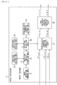
- FIG. 11 is a diagram illustrating a configuration example of an embodiment of the audio processor to which the present technology is applied.
- An audio processor 11 illustrated in FIG. 11 is a signal processing device that is incorporated in, for example, headphones or the like, and receives the input signal D' n m ( ⁇ ) of the spherical harmonic domain, which is an acoustic signal of sound to be reproduced, and outputs drive signals of two-channel sound of a time domain. It is to be noted that, although description is given of a case where the audio processor 11 is incorporated in the headphones, the audio processor 11 may be incorporated in any other device different from the headphones, or may be any other device different from the headphones or the like.
- the audio processor 11 includes a head rotation sensor unit 21, a previous direction holding unit 22, a rotation matrix operation unit 23, a rotation operation unit 24, a rotation coefficient holding unit 25, a head-related transfer function holding unit 26, a head-related transfer function synthesis unit 27, and a time frequency inverse transformation unit 28.
- the head rotation sensor unit 21 includes, for example, an acceleration sensor, an image sensor, and the like attached to the head of the listener (user) as necessary.
- the head rotation sensor unit 21 detects rotation (movement) of the head of the listener, and supplies a detection result to the rotation matrix operation unit 23.
- the listener herein refers to a user who wears headphones, that is, a user who listens to sound reproduced by headphones on the basis of drive signals of left and right headphones obtained by the time frequency inverse transformation unit 28.
- the angle ⁇ t , the angle ⁇ t , and the angle ⁇ t at the time t that is the current time are obtained as a result of detecting the rotation of the head of the listener, that is, a direction in which the head of the listener is directed.
- information that includes the angle ⁇ t , the angle ⁇ t , and the angle ⁇ t and indicates the direction (rotation) of the head of the listener is also referred to as head rotation information.
- the direction at a certain time t indicated by the head rotation information is the angle gt corresponding to the direction g described above, and is angle information that indicates the direction of the head with reference to the x-axis direction, for example.
- the previous direction holding unit 22 holds angles at each time supplied from the rotation matrix operation unit 23 as previous direction information, and supplies the previous direction information held at a time subsequent to the time to the rotation matrix operation unit 23. Accordingly, for example, in a case where the head rotational information at the time t is supplied from the head rotation sensor unit 21 to the rotation matrix operation unit 23, the angle g t-1 at the time t-1 is supplied as the previous direction information from the previous direction holding unit 22 to the rotation matrix operation unit 23.
- the rotation matrix operation unit 23 holds a table indicating the rotation matrix R'(u( ⁇ )) at each angle ⁇ and a table indicating the rotation matrix R'(a( ⁇ )) at each angle ⁇ . It is to be noted that the table indicating the rotation matrix R'(u( ⁇ )) is also used to determine the rotation matrix R'(u( ⁇ )). That is, a common table is used for the rotation matrix R'(u( ⁇ )) and the rotation matrix R'(u( ⁇ )).
- the rotation matrix operation unit 23 determines and outputs the rotation matrix R'(u( ⁇ t )), the rotation matrix R'(a( ⁇ t )), and the rotation matrix R'(u( ⁇ t )) on the basis of the held tables, the head rotational information supplied from the head rotation sensor unit 21, and the previous direction information supplied from the previous direction holding unit 22.
- the rotation matrix operation unit 23 supplies the rotation matrix R'(u( ⁇ t )), the rotation matrix R'(a( ⁇ t )), and the rotation matrix R'(u( ⁇ t )) to the rotation operation unit 24.
- the rotation matrix R'( ⁇ g t ) that is a synthesis of the rotation matrix R'(u( ⁇ t )), the rotation matrix R'(a( ⁇ t )), and the rotation matrix R'(u( ⁇ t )) is a rotation matrix for performing rotation by an angle of a difference (the difference ⁇ g t ) between rotation gt of the head of the listener at the time t and rotation g t-1 of the head of the listener at the time (t-1).
- the rotation matrix operation unit 23 may determine, without using the tables, the rotation matrix R'(u( ⁇ t )), the rotation matrix R'(a( ⁇ t )), and the rotation matrix R'(u( ⁇ t )) by an operation on the basis of the difference ⁇ t , the difference ⁇ t , and the difference ⁇ t .
- the table of rotation matrix R'(a( ⁇ t )) may indicate the rotation matrix Rs'(a( ⁇ t )) that is an approximation of the rotation matrix R'(a( ⁇ t )), or the rotation matrix Rs'(a( ⁇ t )) may be determined not from the tables but by an operation.
- the rotation matrix operation unit 23 supplies head rotation information gt supplied from the head rotation sensor unit 21 as previous direction information to the previous direction holding unit 22 and causes the previous direction holding unit 22 to hold the head rotation information gt.
- the rotation operation unit 24 calculates the row vector H'(g t -1 , ⁇ ) and supplies the row vector H'(g t -1 , ⁇ ) to the rotation coefficient holding unit 25 and the head-related transfer function synthesis unit 27.
- the row vector H'(g t -1 , ⁇ ) is a row vector obtained by performing a rotation operation that causes the head-related transfer function in the spherical harmonic domain, that is, the row vector H S ( ⁇ ) to be rotated by the angle gt on the basis of the rotation matrix R'(g t ) at the time t.
- the rotation operation unit 24 calculates the row vector H'(g t -1 , ⁇ ) at the time t on the basis of the rotation matrix R'( ⁇ g t ) supplied from the rotation matrix operation unit 23 and a row vector H'(g t-1 -1 , ⁇ ) at the time (t-1) supplied from the rotation coefficient holding unit 25.
- Such an operation is a rotation operation in which an operation result of a rotation operation at the time (t-1) is further rotated by an angle indicated by the difference ⁇ g t .
- the operation result is the rotated head-related transfer function obtained by a rotation operation that causes the row vector H S ( ⁇ ) to be rotated by the angle g t-1 .
- the rotation operation on the basis of the rotation matrix R'( ⁇ g t ) is a matrix operation in which only elements having the order k within a range determined by the predetermined value C in the rotation matrix R'( ⁇ g t ) are calculated, that is, an operation limited by the order k is performed. Accordingly, it can be said that the rotation matrix R'( ⁇ g t ) is a rotation matrix in which only elements having the order k within the range determined by the predetermined value C are elements having a non-zero effective value, that is, a rotation limited by the order k
- the rotation operation unit 24 calculates the row vector H'(g t -1 , ⁇ ) on the basis of the row vector H S ( ⁇ ) of the head-related transfer function supplied from the head-related transfer function holding unit 26 and the rotation matrix R'( ⁇ g t ) supplied from the rotation matrix operation unit 23 at the start of processing, that is, in the absence of the row vector H'(g t-1 -1 , ⁇ ).
- the angle g t-1 is 0 degrees; therefore, the rotation matrix R'( ⁇ g t ) is equivalent to the rotation matrix R'(g t ).
- the rotation coefficient holding unit 25 holds the row vector H'(gt -1 , ⁇ ) at the time t supplied from the rotation operation unit 24, and supplies the row vector H'(gt -1 , ⁇ ) held at a subsequent time (t+1) to the rotation operation unit 24.
- the head-related transfer function holding unit 26 holds the predetermined row vector H S ( ⁇ ) or the row vector H S ( ⁇ ) supplied from outside, and supplies the held row vector H S ( ⁇ ) to the rotation operation unit 24. It is to be noted that the row vector H S ( ⁇ ) may be prepared for each listener (user), or the common row vector H S ( ⁇ ) may be prepared for all listeners or a plurality of listeners included in one group.
- the row vector H'(g -1 , ⁇ ) is a matrix obtained by rotating the row vector H S ( ⁇ ) including the head-related transfer function in the spherical harmonic domain by the rotation matrix R'(g -1 ), that is, a matrix including the head-related transfer function after rotation.
- the row vector H'(g -1 , ⁇ ) is a matrix (vector) including, as an element, a head-related transfer function rotated by angles determined by the direction of the head of the listener in the spherical harmonic domain, that is, by the angle ⁇ in the horizontal direction, the angle ⁇ in the elevation angle direction, and the angle ⁇ in the horizontal direction.
- the head-related transfer function synthesis unit 27 synthesizes the input signal D' n m ( ⁇ ) for each of the time frequency bins ⁇ supplied from outside and the row vector H'(g t -1 , ⁇ ) supplied from the rotation operation unit 24 to generate the drive signals of the left and right headphones.
- the input signal D' n m ( ⁇ ) is a sound signal of the spherical harmonic domain.
- the head-related transfer function synthesis unit 27 calculates the drive signal P l (g, ⁇ ) and the drive signal P r (g, ⁇ ) of the left and right headphones by determining the product of the row vector H'(g t -1 , ⁇ ) and the matrix D'( ⁇ ) including the input signal D' n m ( ⁇ ) for each of the left and right headphones, and supplies the drive signal P l (g, ⁇ ) and the drive signal P r (g, ⁇ ) to the time frequency inverse transformation unit 28.
- the input signal D' n m ( ⁇ ) is the sound signal of the spherical harmonic domain.
- the drive signal P l (g, ⁇ ) is a drive signal (binaural signal) of the left headphone in the time frequency domain and the drive signal P r (g, ⁇ ) is a drive signal (binaural signal) of the right headphone in the time frequency domain.
- the head-related transfer function synthesis unit 27 synthesis of the head-related transfer function on the input signal and spherical harmonic inverse transformation on the input signal are performed simultaneously.
- the time frequency inverse transformation unit 28 performs time frequency inverse transformation on the drive signals in the time frequency domain supplied from the head-related transfer function synthesis unit 27 for the respective left and right headphones to determine the drive signal p l (g, t) of the left headphone in the time domain and the drive signal p r (g, t) of the right headphone in the time domain, and outputs these drive signals to a subsequent stage.
- a reproduction device that reproduces sound by two channels or a plurality of channels, such as headphones in the subsequent stage, more specifically, headphones including earphones and speakers using transaural technology, sound is reproduced on the basis of the drive signals outputted from the time frequency inverse transformation unit 28.
- a time frequency transformation unit is provided in an signal input portion, that is, in a previous stage of the head-related transfer function synthesis unit 27, for example, or a convolution operation in the time domain is performed in the head-related transfer function synthesis unit 27.
- the rotation matrix operation unit 23 determines the difference ⁇ t , the difference ⁇ t , and the difference ⁇ t from the difference ⁇ g t , reads, from the tables of the held rotation matrix R'(a( ⁇ )) and the held rotation matrix R'(u( ⁇ )), the rotation matrix R'(a( ⁇ )) in a case where the angle ⁇ is the difference ⁇ t , and the rotation matrix R'(u( ⁇ )) in a case where the angle ⁇ is the difference ⁇ t and the difference ⁇ t , and sets the rotation matrices as the rotation matrix R'(a( ⁇ t )), the rotation matrix R'(u( ⁇ t )), and the rotation matrix R(u( ⁇ t )).
- the rotation matrix operation unit 23 performs an operation similar to the expression (29) described above, and synthesizes the thus-obtained rotation matrix R'(a( ⁇ t )), the thus-obtained rotation matrix R'(u( ⁇ t )), and the thus-obtained rotation matrix R(u( ⁇ t )) to obtain the rotation matrix R'( ⁇ g t ).
- the difference ⁇ t is as illustrated in FIG. 12 .
- a vertical axis represents the angle ⁇ (elevation angle ⁇ ) at each time
- a horizontal axis represents time.
- a curve L11 represents the angles ⁇ at respective times, and an enlarged portion of a region RZ11 in the curve L11 is as illustrated in a portion on a lower side of the diagram.
- a period from the time t-1 to the time t is a period of one frame. Accordingly, a difference between the angle ⁇ t and the angle ⁇ t-1 is ⁇ t .
- the angle ⁇ t is the angle ⁇ at the time t
- the angle ⁇ t-1 is the angle ⁇ at the time t-1.
- the rotation matrix R'( ⁇ g t ) obtained on the basis of the difference ⁇ g t is supplied to the rotation operation unit 24, and the angle g t at the time t is supplied to the previous direction holding unit 22 to update the previous direction information. That is, the newly supplied angle g t at the time t is held as the updated previous direction information.
- the row vector H'(g t -1 , ⁇ ) at the time t is calculated on the basis of the rotation matrix R'( ⁇ g t ) and the row vector H'(g t-1 -1 , ⁇ ) at the time (t-1).
- the rotation operation unit 24 obtains the row vector H'(g t -1 , ⁇ ) by calculating the expression (41).
- (2C+1) elements having the order k ranging from m-C to m+C, where m is set as a center are calculated similarly to the expression (36) described above.
- the order k is limited to a range of -n ⁇ k ⁇ n. That is, the operation is performed only on elements in which the order k has a value within a range determined by C, which is the operation in which the order k is limited, and the operation amount is reduced.
- the rotation matrix R'(a( ⁇ t )) may be sequentially determined by calculation, or the rotation matrix R'(a( ⁇ t )) may be selected from one or a plurality of candidates prepared in advance.
- a method of performing an operation on the rotation matrix R'(a( ⁇ t )) by the time and a method of selecting the rotation matrix R'(a( ⁇ t )) from one or a plurality of candidates may be combined, and an angle by which the head-related transfer function is rotated by tracking the actual angle ⁇ t of rotation of the head of the listener may be adjusted while changing frequency of using these respective methods.
- step S11 the head rotation sensor unit 21 detects rotation of the head of the user who is the listener, and supplies head rotation information obtained as a result of the detection to the rotation matrix operation unit 23.
- step S12 the rotation matrix operation unit 23 determines the difference ⁇ g t between the angle g t of the head rotational information supplied from the head rotation sensor unit 21 and the angle g t-i at the time (t-1) held as the previous direction information in the previous direction holding unit 22.
- the rotation matrix operation unit 23 supplies the angle gt of the head rotational information obtained in the step S11 to the previous direction holding unit 22 to update the previous direction information.
- the previous direction holding unit 22 updates the previous direction information to cause the angle g t supplied from the rotation matrix operation unit 23 to become new previous direction information, and holds a thus-updated result.
- step S13 on the basis of the difference ⁇ g t obtained in the step S12, the rotation matrix operation unit 23 determines the rotation matrix R'(a( ⁇ t )) in the elevation angle direction corresponding to the difference ⁇ t of the difference ⁇ g t . It is to be noted that, in the step S13, the rotation matrix operation unit 23 may determine, as the rotation matrix R'(a( ⁇ t )), the rotation matrix Rs'(a( ⁇ t )) corresponding to the difference ⁇ t . The rotation matrix Rs'(a( ⁇ t )) corresponds to the rotation matrix Rs'(a( ⁇ )).
- step S14 on the basis of the difference ⁇ t and the difference ⁇ t in rotation of the head determined from the difference ⁇ g t that is obtained in the step S12, the rotation matrix operation unit 23 determines the rotation matrix R'(u( ⁇ t )) and the rotation matrix R'(u( ⁇ t )) in the horizontal direction corresponding to the differences ⁇ t and ⁇ t .
- step S15 the rotation matrix operation unit 23 synthesizes the rotation matrix R'(a( ⁇ t )) in the elevation angle direction obtained in the step S13 and the rotation matrix R'(u( ⁇ t )) and the rotation matrix R'(u( ⁇ t )) in the horizontal direction obtained in the step S14 to determine the rotation matrix R'( ⁇ g t ) for performing rotation by a difference in rotation of the entire head, and supplies the rotation matrix R'( ⁇ g t ) to the rotation operation unit 24.
- step S16 the rotation operation unit 24 performs a rotation operation on the basis of the rotation matrix R'( ⁇ g t ) supplied from the rotation matrix operation unit 23 and the row vector H'(g t-1 -1 , ⁇ ) held in the rotation coefficient holding unit 25.
- the expression (41) described above is calculated as a rotation operation on the basis of the effective element width 2C+1 determined by the constant C to calculate the row vector H'(g t -1 , ⁇ ).
- the rotation operation unit 24 supplies the obtained row vector H'(g t -1 , ⁇ ) to the rotation coefficient holding unit 25, and causes the rotation coefficient holding unit 25 to hold the row vector H'(g t -1 , ⁇ ), and also supplies the row vector H'(g t -1 , ⁇ ) to the head-related transfer function synthesis unit 27.
- step S17 the head-related transfer function synthesis unit 27 synthesizes the supplied input signal D' n m ( ⁇ ) and the row vector H'(g t -1 , ⁇ ) of the head-related transfer function supplied from the rotation operation unit 24 to generate drive signals of the left and right headphones.
- the product of the row vector H'(g t -1 , ⁇ ) and the matrix D'( ⁇ ) is determined for each of the left and right headphones to calculate the drive signal P l (g, ⁇ ) and the drive signal P r (g, ⁇ ) of the left and right headphones.
- the head-related transfer function synthesis unit 27 supplies the obtained drive signal P l (g, ⁇ ) and the obtained drive signal P r (g, ⁇ ) to the time frequency inverse transformation unit 28.
- step S18 the time frequency inverse transformation unit 28 performs time frequency inverse transformation on the drive signal P l (g, ⁇ ) and the drive signal P r (g, ⁇ ) supplied from the head-related transfer function synthesis unit 27, and outputs, to a subsequent stage, the drive signal P l (g, t) and the drive signal P r (g, t) that are obtained as results of the time frequency inverse transformation, and the drive signal generation processing ends.
- the audio processor 11 determines the rotation matrix R'( ⁇ gt) on the basis of the difference ⁇ g t , and determines the current row vector H'(g t -1 , ⁇ ) on the basis of the rotation matrix R'( ⁇ g t ) and the previous row vector H'(gt -1 -1 , ⁇ ).
- an operation of an operation amount of a cube order of the degree n is necessary to determine the row vector H'(g t -1 , ⁇ ) at the time of resetting, but performing the resetting less frequently makes it possible to reduce the operation amount as a whole.
- the audio processor 11 is configured as illustrated in FIG. 14 . It is to be noted that, in FIG. 14 , components corresponding to those in FIG. 11 are denoted by the same reference numerals, and description thereof is omitted as appropriate.
- the audio processor 11 illustrated in FIG. 14 includes the head rotation sensor unit 21, the previous direction holding unit 22, the rotation matrix operation unit 23, the rotation operation unit 24, the rotation coefficient holding unit 25, the head-related transfer function holding unit 26, the head-related transfer function synthesis unit 27, and the time frequency inverse transformation unit 28.
- the audio processor 11 illustrated in FIG. 14 is the same as the audio processor 11 in FIG. 11 in including components from the head rotation sensor unit 21 to the time frequency inverse transformation unit 28, but differs from the audio processor 11 in FIG. 11 in that a reset trigger that is a signal indicating a timing of the resetting is supplied to the rotation matrix operation unit 23 and the rotation operation unit 24.
- the rotation matrix operation unit 23 determines the rotation matrix R( ⁇ gt) on the basis of the angle gt of the head rotational information and the angle gt-i as the previous direction information, and supplies the rotation matrix R( ⁇ gt) to the rotation operation unit 24.
- the rotation matrix operation unit 23 determines the rotation matrix R'(gt) on the basis of the angle gt of the head rotation information and supplies the rotation matrix R'(gt) to the rotation operation unit 24. That is, the resetting is performed to determine the accurate rotation matrix R'(gt). In other words, a rotation matrix determined by a difference such as rotation matrix R'( ⁇ gt) is not determined, but the absolute the rotation matrix R'(gt) is determined.
- the rotation operation unit 24 calculates the row vector H'(g t -1 , ⁇ ) on the basis of the rotation matrix R'( ⁇ g t ) supplied from the rotation matrix operation unit 23 and the row vector H'(g t-1 -1 , ⁇ ) held in the rotation coefficient holding unit 25.
- the rotation operation unit 24 calculates the row vector H'(g t -1 , ⁇ ) on the basis of the rotation matrix R'(gt) supplied from the rotation matrix operation unit 23 and the row vector H s ( ⁇ ) of the head-related transfer function held in the head-related transfer function holding unit 26.
- the row vector H'(g t -1 , ⁇ ) is calculated by performing calculation similar to that in the expression (35) or the expression (36) described above. That is, the product of the rotation matrix R'(gt) and the row vector H s (( ⁇ ) is determined to calculate the row vector H'(g t -1 , ⁇ ).
- the resetting is performed in response to input of the reset trigger to determine the accurate rotation matrix R'(gt) and the row vector H'(g t -1 , ⁇ ), which makes it possible to obtain a drive signal having a small error while keeping the necessary memory amount the necessary operation amount low.
- the reset trigger is turned on or off at an optional timing, but the reset trigger may be turned on at all time. That is, the rotation matrix R'(gt) may be calculated at all times.
- the reset trigger may be turned on at any timing.
- the timing at which the reset trigger is turned on may be a predetermined regular (periodic) timing such as a predetermined time interval, a timing at which the difference ⁇ t becomes equal to or greater than a threshold value, or a timing at which the angle ⁇ t becomes equal to or greater than a predetermined value.
- step S51 is the same as that in the step S11 in FIG. 13 , and the description thereof is omitted.
- step S52 the rotation matrix operation unit 23 determines whether or not to perform the resetting on the basis of the reset trigger supplied from outside. For example, in a case where the reset trigger is turned on, it is determined to perform resetting.
- step S52 In a case where it is determined not to perform the resetting in the step S52, the processing proceeds to step S53, and processes in steps S53 to S57 are performed.
- step S57 The process in the step S57 is performed, and then the rotation operation unit 24 supplies the obtained row vector H'(g t -1 , ⁇ ) to the head-related transfer function synthesis unit 27 and the rotation coefficient holding unit 25, and thereafter, the processing proceeds to step S60.
- step S58 the rotation matrix operation unit 23 determines the rotation matrix R'(a( ⁇ t )) in the elevation angle direction, and the rotation matrix R'(u( ⁇ t )) and the rotation matrix R'(u( ⁇ t )) in the horizontal direction on the basis of the angle gt of the head rotation information supplied from the head rotation sensor unit 21.
- the rotation matrix operation unit 23 synthesizes the rotation matrix R'(a( ⁇ t )), the rotation matrix R'(u( ⁇ t )), and the rotation matrix R'(u( ⁇ t )) to determine the rotation matrix R'(gt), and supplies the rotation matrix R'(gt) to the rotation operation unit 24.
- the rotation matrix R'(a( ⁇ t )) may be obtained from the table on the basis of the angle ⁇ t , or the rotation matrix R'(a( ⁇ t )) may be obtained by an operation on the basis of the angle ⁇ t .
- the rotation matrix R'(u( ⁇ t )) and the rotation matrix R'(u( ⁇ t )) may be determined by an operation on the basis of the angle ⁇ t and the angle ⁇ t , or the rotation matrix R'(u( ⁇ t )) and the rotation matrix R'(u( ⁇ t )) may be obtained from the table on the basis of the angle ⁇ t and the angle ⁇ t .
- step S59 the rotation operation unit 24 performs a rotation operation on the basis of the rotation matrix R'(gt) supplied from the rotation matrix operation unit 23 and the row vector H s ( ⁇ ) of the head-related transfer function held in the head-related transfer function holding unit 26 to calculate the row vector H'(g t -1 , ⁇ ).
- the row vector H'(g t -1 , ⁇ ) is calculated by performing calculation similar to that in the expression (35) or the expression (36) described above.
- the row vector H'(g t -1 , ⁇ ) is obtained, and then the rotation operation unit 24 supplies the obtained row vector H'(g t -1 , ⁇ ) to the head-related transfer function synthesis unit 27 and the rotation coefficient holding unit 25, and thereafter, the processing proceeds to step S60.
- step S57 or the step S59 After the process in the step S57 or the step S59 is performed, processes in step S60 and step S61 are performed, and the drive signal generation processing ends; however, these processes are the same as those in the step S17 and the step S18 in FIG. 13 , and the description thereof is omitted.
- the audio processor 11 determines the accurate rotation matrix R'(gt) and the accurate row vector H'(g t -1 , ⁇ ) to generate the drive signal. Doing so makes it possible to obtain a drive signal having a small error while keeping the necessary memory amount and the necessary operation amount low.
- the difference ⁇ t abruptly increases. Accordingly, in a case where the row vector H'(g t -1 , ⁇ ) is intended to be determined by tracking rotation of the head of the listener, if the row vector H'(g t -1 , ⁇ ) is intended to be determined accurately, the operation amount increases, and if the row vector H'(g t -1 , ⁇ ) is intended to be determined with a small operation amount, the error increases.
- the value of the difference ⁇ t may be limited to a value equal to or less than one degree regardless of the actual value of the difference ⁇ t , and the rotation matrix operation unit 23 may determine the rotation matrix R'(a( ⁇ t )).
- the rotation matrix operation unit 23 may determine the rotation matrix R'(a( ⁇ t )) only for the elements in the block having the effective element width 2C+1 determined for C, which is used as a predetermined value, that determines the effective element width 2C+1, that is, only for the effective elements.
- calculation of the expression (36) is performed only for the effective elements determined for C to determine the row vector H'(g t -1 , ⁇ ).
- the operation amount is increased because of use of the rotation matrix R'(gt), but only an operation only for the effective elements determined by C that determines the effective element width 2C+1 is sufficient, which makes it possible to keep the operation amount low to some extent while tracking rotation of the head of the listener. It is also possible to perform such processing independently of turning the reset trigger on or off.
- the rotation operation unit 24 may temporarily increase C determining the effective element width 2C+1 to a value greater than a normal value.
- the value of C may be a constant, or may be determined by the degree n, the difference ⁇ t , or the like.
- the resetting may be performed, for example, in a case where the angle ⁇ t of the head rotation information becomes a predetermined value (hereinafter, also referred to as reset point).
- the rotation matrix operation unit 23 holds the rotation matrix R'(a( ⁇ )) determined in advance for the angle ⁇ , which is the reset point, for every reset point or every plurality of reset points. For example, it is assumed that the rotation matrix R'(a( ⁇ 1 )) is held in advance for an angle ⁇ 1 determined as the reset point.
- the rotation matrix operation unit 23 determines the rotation matrix R'(gt) with use of the held rotation matrix R'(a( ⁇ 1 )) as the rotation matrix R'(a( ⁇ t )), and supplies the rotation matrix R'(gt) to the rotation operation unit 24.
- a memory is necessary to hold the rotation matrix R'(a( ⁇ )) for each reset point, but it is not necessary to perform an operation of the rotation matrix R'(a( ⁇ t )), which makes it possible to keep the operation amount low while performing the resetting to obtain the accurate rotation matrix R'(a( ⁇ t )).
- each of a plurality of audio processors outputs a drive signal to each of the headphones and the like worn by each of the listeners.
- the control system illustrated in FIG. 16 includes audio processors 71-1 to 71-4 and a switch 72.
- Each of the audio processors 71-1 to 71-4 has the same configuration as that of the audio processor 11 illustrated in FIG. 14 .
- the audio processors 71-1 to 71-4 are also simply referred to as audio processors 71.
- Each of the audio processor 71 receives the input signal D' n m ( ⁇ ), performs processing similar to the drive signal generation processing described with reference to FIG. 15 , and outputs the drive signal p 1 (g, t) and the drive signal p r (g, t) of the left and right headphones.
- each of the audio processors 71 may be one independent device, or these audio processors 71 may be provided in one device, but it is assumed herein that the respective audio processors 71 are provided in one computing system (device) located in a middle.
- the switch 72 controls supply of the reset trigger to the audio processors 71 to supply the reset trigger to one audio processor 71 of the audio processors 71-1 to 71-4 at an optional timing.
- each of the plurality of listeners wears headphones, and each of the headphones reproduces sound on the basis of the drive signal supplied from each of the audio processors 71 that are different from each other.
- each of the audio processors 71 detects movement (rotation) of the headphones to which the drive signal is to be outputted, that is, movement (rotation) of the head of the listener wearing the headphones in the head rotation sensor unit 21, and rotates the head-related transfer function by tracking the movement of the head of the listener, and generates the drive signal.
- the reset trigger is supplied to each of the four audio processors 71 by the switch 72 at different timings; therefore, the resetting is not performed simultaneously on the audio processors 71. This makes it possible to suppress a sudden increase in an operation load in the entire control system. That is, it is possible to prevent a temporary increase in the operation amount.
- the operation amount in the entire control system temporarily becomes large (increases) at a time at which the resetting is performed, as indicated by an arrow Q11 in FIG. 17 , for example.
- a vertical axis represents the operation amount in the entire control system, and a horizontal axis represents time.
- the resetting is performed simultaneously on the four audio processors 71 in the control system at predetermined intervals.
- the resetting is performed at a time t11, and the operation amount becomes large (increases) at the time t11, but the operation amount is kept low at other times at which the resetting is not performed.
- the resetting is not performed simultaneously on the plurality of audio processors 71, but the resetting is performed on the respective audio processors 71 at different timings.
- the operation amount increases with a higher frequency, but the operation amount at each time does not become so large. That is, although the operation amount rises at the time of the resetting, an increase in the operation amount at that time is only an amount corresponding to the resetting on one audio processor 71; therefore, the operation load to be applied is not as large as the operation load applied in a case where the resetting is performed simultaneously on the plurality of audio processors 71.
- the resetting is performed on one audio processor 71, but the operation amount is kept low, as compared with that at the time t11 in the example indicated by the arrow Q11.
- all the audio processors 71 may be divided into a plurality of groups including one or a plurality of audio processors 71, and the resetting may be performed on each of the groups.
- the resetting is performed on the respective audio processors 71 at timing different from each other, which makes it possible to suppress a temporary increase in the operation amount.
- the resetting may be performed for each degree n or for each order m regardless of the example of the audio processor 11 illustrated in FIG. 14 and the example of the control system illustrated in FIG. 16 , that is, regardless of whether one or a plurality of listeners exist. Doing so makes it possible to suppress an increase in the operation load at the time of the resetting.
- the resetting may be performed only on a component of a predetermined degree for the degree n. At this time, the resetting may be performed on components of the respective degrees at different timings, or the resetting may be performed simultaneously on components of some of the degrees.
- the product of the rotation matrix R'(gt) and the row vector H s ( ⁇ ) for the zeroth-order component is determined to generate the matrix H 0 ( ⁇ ).
- the product of the rotation matrix R'( ⁇ gt) and the row vector H'(g t-1 -1 , ⁇ ) is determined, that is, calculation of the expression (41) is performed to generate the matrix H 1 ( ⁇ ), the matrix H 2 ( ⁇ ), and the matrix H 3 ( ⁇ ).
- the final row vector H'(g t -1 , ⁇ ) is obtained from the matrix H 0 ( ⁇ ), the matrix H 1 ( ⁇ ), the matrix H 2 ( ⁇ ), and the matrix H 3 ( ⁇ ) that are thus obtained.
- the process in the step S58 in FIG. 15 and the process in the step S59 in FIG. 15 are performed on the zeroth-order component to generate the matrix H 0 ( ⁇ ).
- the processes in the steps S53 to S57 are performed to generate the matrix H 1 ( ⁇ ), the matrix H 2 ( ⁇ ), and the matrix H 3 ( ⁇ ).
- the row vector H'(g t -1 , ⁇ ) is generated from the matrix H 0 ( ⁇ ), the matrix H 1 ( ⁇ ), the matrix H 2 ( ⁇ ), and the matrix H 3 ( ⁇ ).
- some groups such as a group including zeroth and first orders of the degree n may be provided, and the resetting may be performed for each of the group.
- the number of elements is small from the zeroth to second orders of the degree n; therefore, the zeroth to second orders of the degree n may be set as one group, and the resetting may be performed simultaneously on the zeroth-order, first-order, and second-order components of the degree n.
- a timing at which the resetting is performed on the zeroth-order, first-order, and second-order components of the degree n is different from a timing at which the resetting is performed on the third-order component of the degree n.
- the resetting may be performed for each time frequency ⁇ regardless of the example of the audio processor 11 illustrated in FIG. 14 and the example of the control system illustrated in FIG. 16 , that is, regardless of whether one or a plurality of listeners exists. Doing so makes it possible to suppress an increase in the operation load at the time of the resetting.
- the number of time frequency bins ⁇ is W
- the row vector H'(g t -1 , ⁇ ) is determined for W number of time frequencies ⁇ 1 to ⁇ w . That is, row vectors H'(g t -1 , ⁇ 1 ) to H'(g t -1 , ⁇ w ) are obtained.
- resetting may be performed only for a predetermined time frequency ⁇ .
- the resetting may be performed at different timings for the respective time frequencies ⁇ , or the resetting may be performed simultaneously for some time frequencies ⁇ .
- the processes in the steps S58 and S59 in FIG. 15 are performed for the time frequency ⁇ 1 to generate the row vector H'(g t -1 , ⁇ 1 ).
- some groups such as a group including one or a plurality of time frequencies ⁇ may be provided, and the resetting may be performed for each of the groups.
- the audio processors 71 corresponding to a plurality of listeners are operated by one computing system located in the middle.
- a system (slave) for each listener such as a smartphone, may independently perform processing of generating a drive signal for each listener, and the slave does not have sufficient processing performance to perform the resetting described above
- a device (master) in the middle to which the slave is coupled may perform a portion or the entirety of an operation at the time of the resetting.
- control system is configured, for example, as illustrated in FIG. 20 .
- the control system illustrated in FIG. 20 includes a master device 101 and slave 102-1 to slave 102-9.
- the master device 101 and each of the slaves 102-1 to 102-9 are coupled to each other through a wired or wireless network. It is to be noted that, hereinafter, in a case where it is not necessary to particularly distinguish the slaves 102-1 to 102-9, the slaves 102-1 to 102-9 are also simply referred to as slaves 102.
- the master device 101 performs a portion of an operation (processing) originally performed in the slaves 102, and supplies a result of the operation result to the slaves 102.
- the slaves 102 each include, for example, headphones, a smartphone, or the like, and correspond to the audio processor 11 illustrated in FIG. 14 .
- the slaves 102 each perform the drive signal generation processing described with reference to FIG. 15 in accordance with rotation of the head of the listener, and outputs the drive signal, but requests the master device 101 to perform a portion of an operation of the drive signal generation processing, such as an operation at the time of the resetting.
- the master device 101 it is possible for the master device 101 to perform the operation at the time of the resetting, for example.
- the slave 102 transmits, to the master device 101, an operation request for calculation of the row vector H'(g t -1 , ⁇ ) together with the angle gt or the rotation matrix R'(gt).
- the master device 101 that has received the operation request from the slave 102 and the angle gt or the rotation matrix R'(gt) performs an operation of the following expression (42) in response to the operation request, and transmits the resultant row vector H'(g t -1 , ⁇ ) to the slave 102.
- H ′ g t ⁇ 1 ⁇ H s ⁇ R ′ g t
- the row vector H s ( ⁇ ) to be used in the operation of the expression (42) may be obtained from the slave 102 by the master device 101 in advance, or may be held in the master device 101 in advance.
- the slave 102 In such a manner, it is possible for the slave 102 to obtain a drive signal of sound to be presented to the listener with a small operation amount with use of the row vector H'(g t -1 , ⁇ ) received from the master device 101.
- the resetting may be performed for each listener, each degree n, each order m, each time frequency co, or the like, and appropriately determining the timing of the resetting makes it possible to reduce the operation load on the master device 101. For example, performing the resetting for the respective slaves 102 at different timings makes it possible to reduce the operation load on the master device 101.
- the slave 102 may perform the operation at the time of the resetting.
- the master device 101 sequentially receives the angle gt, the rotation matrix R'( ⁇ gt), or the like from the slave 102, performs an operation expressed by the following expression (43), and calculates the row vector H'(g t -1 , ⁇ ).
- the master device 101 may perform operations up to the calculation of the row vector H'(g t -1 , ⁇ ) and the slave 201 may perform the remaining operations up to obtaining of the drive signal, or the master device 101 may calculate the drive signal with use of the row vector H'(g t -1 , ⁇ ) and supply the drive signal to the slave 102.
- the slave 102 performs the operation of the expression (42) described above, and the resultant row vector H'(g t - , ⁇ ) is transmitted from the slave 102 to the master device 101.
- the slave 102 performs the operation at the time of the resetting in such a manner, which makes it possible for the master device 101 to update the row vector H'(g t -1 , ⁇ ) that is normally calculated on the basis of a difference to the more accurate row vector H'(g t -1 , ⁇ ), and reset an error.
- the row vector H s ( ⁇ ) necessary for the operation at the time of the resetting may be obtained from the master device 101 by the slave 102 in advance, may be held in the slave 102 in advance, or may be held in both the master device 101 and the slave 102 in advance.
- the row vector H s ( ⁇ ) or the like held by the one device may be transmitted to the other device at an optional timing such as the time of coupling or the time of initialization.
- the resetting may be performed for each listener, each degree n, each order m, each time frequency co, or the like, and it is possible to appropriately determine the timing of the resetting.
- the operation at the time of the resetting is performed by the slave 102, the operation at the time of the resetting for a plurality of listeners is not performed simultaneously in one slave 102; therefore, it is not necessary to disperse the timing of the resetting.
- the master device 101 and the slave 102 may share the drive signal generation processing described with reference to FIG. 13 and FIG. 15 . That is, the master device 101 has some of functions to perform the drive signal generation processing, which makes it possible to flexibly cope with a case where the number of listeners increases dynamically, and the like.
- the series of processing is executed by the software
- a program including that software is installed in a computer.
- the computer includes a computer incorporated into dedicated hardware and, for example, a general-purpose computer capable of executing various functions by being installed with various programs.
- FIG. 21 is a block diagram illustrating a configuration example of the hardware of the computer that executes the series of processing described above by a program.
- a CPU Central Processing Unit
- ROM Read Only Memory
- RAM Random Access Memory
- a input/output interface 505 is further coupled to the bus 504.
- An input unit 506, an output unit 507, a recording unit 508, a communication unit 509, and a drive 510 are coupled to the input/output interface 505.
- the input unit 506 includes a keyboard, a mouse, a microphone, an imaging element, and the like.
- the output unit 507 includes a display, a speaker, and the like.
- the recording unit 508 includes a hard disk, a nonvolatile memory, and the like.
- the communication unit 509 includes a network interface and the like.
- the drive 510 drives a removable recording medium 511 such as a magnetic disk, an optical disk, a magneto-optical disk, or a semiconductor memory.
- the CPU 501 loads, for example, a program recorded on the recording unit 508 into the RAM 503 through the input/output interface 505 and the bus 504, and executes the program, thereby performing the series of processing described above.
- the program it is possible to record the program to be executed by the computer (the CPU 501), for example, in the removable recording medium 511 as a package medium or the like and provide the program. Moreover, it is possible to provide the program through a wired or wireless transmission medium such as a local area network, the Internet, digital satellite broadcasting, or the like.
- the computer it is possible to install the program in the recording unit 508 through the input/output interface 505 by mounting the removable recording medium 511 to the drive 510. Further, it is possible to receive the program by the communication unit 509 through the wired or wireless transmission medium and install the program on the recording unit 508. In addition, it is possible to install the program on the ROM 502 or the recording unit 508 in advance.
- the program to be executed by the computer may be a program in which processing is performed in time series in sequence described in this specification, or may be a program in which processing are performed in parallel or at a necessary timing such as when a timing at which calling is performed.
- embodiments of the present technology are not limited to the foregoing embodiments, and may be modified in variety of ways in a scope without departing from the gist of the present technology.
- the present technology it is possible for the present technology to adopt a configuration of cloud computing in which one function is shared and collaboratively processed by a plurality of devices through a network.
- the present technology may have the following configurations.
Landscapes
- Physics & Mathematics (AREA)
- Engineering & Computer Science (AREA)
- Acoustics & Sound (AREA)
- Signal Processing (AREA)
- Algebra (AREA)
- General Physics & Mathematics (AREA)
- Mathematical Analysis (AREA)
- Mathematical Optimization (AREA)
- Mathematical Physics (AREA)
- Pure & Applied Mathematics (AREA)
- Theoretical Computer Science (AREA)
- Stereophonic System (AREA)
Applications Claiming Priority (2)
| Application Number | Priority Date | Filing Date | Title |
|---|---|---|---|
| JP2017132187 | 2017-07-05 | ||
| PCT/JP2018/023557 WO2019009085A1 (ja) | 2017-07-05 | 2018-06-21 | 信号処理装置および方法、並びにプログラム |
Publications (2)
| Publication Number | Publication Date |
|---|---|
| EP3651480A1 true EP3651480A1 (de) | 2020-05-13 |
| EP3651480A4 EP3651480A4 (de) | 2020-06-24 |
Family
ID=64949936
Family Applications (1)
| Application Number | Title | Priority Date | Filing Date |
|---|---|---|---|
| EP18828168.7A Withdrawn EP3651480A4 (de) | 2017-07-05 | 2018-06-21 | Signalverarbeitungsvorrichtung und -verfahren und programm |
Country Status (5)
| Country | Link |
|---|---|
| US (1) | US11252524B2 (de) |
| EP (1) | EP3651480A4 (de) |
| JP (1) | JP7115477B2 (de) |
| CN (1) | CN110832884B (de) |
| WO (1) | WO2019009085A1 (de) |
Families Citing this family (1)
| Publication number | Priority date | Publication date | Assignee | Title |
|---|---|---|---|---|
| WO2020196004A1 (ja) * | 2019-03-28 | 2020-10-01 | ソニー株式会社 | 信号処理装置および方法、並びにプログラム |
Family Cites Families (14)
| Publication number | Priority date | Publication date | Assignee | Title |
|---|---|---|---|---|
| US6021206A (en) * | 1996-10-02 | 2000-02-01 | Lake Dsp Pty Ltd | Methods and apparatus for processing spatialised audio |
| EP2612322B1 (de) * | 2010-10-05 | 2016-05-11 | Huawei Technologies Co., Ltd. | Verfahren und vorrichtung zur dekodierung eines mehrkanaltonsignals |
| US9641951B2 (en) | 2011-08-10 | 2017-05-02 | The Johns Hopkins University | System and method for fast binaural rendering of complex acoustic scenes |
| EP2688066A1 (de) * | 2012-07-16 | 2014-01-22 | Thomson Licensing | Verfahren und Vorrichtung zur Codierung von Mehrkanal-HOA-Audiosignalen zur Rauschreduzierung sowie Verfahren und Vorrichtung zur Decodierung von Mehrkanal-HOA-Audiosignalen zur Rauschreduzierung |
| US9959875B2 (en) * | 2013-03-01 | 2018-05-01 | Qualcomm Incorporated | Specifying spherical harmonic and/or higher order ambisonics coefficients in bitstreams |
| US9384741B2 (en) | 2013-05-29 | 2016-07-05 | Qualcomm Incorporated | Binauralization of rotated higher order ambisonics |
| CN103888889B (zh) * | 2014-04-07 | 2016-01-13 | 北京工业大学 | 一种基于球谐展开的多声道转换方法 |
| US9794712B2 (en) | 2014-04-25 | 2017-10-17 | Dolby Laboratories Licensing Corporation | Matrix decomposition for rendering adaptive audio using high definition audio codecs |
| US9767618B2 (en) * | 2015-01-28 | 2017-09-19 | Samsung Electronics Co., Ltd. | Adaptive ambisonic binaural rendering |
| WO2016172591A1 (en) * | 2015-04-24 | 2016-10-27 | Dolby Laboratories Licensing Corporation | Augmented hearing system |
| EP3402223B1 (de) * | 2016-01-08 | 2020-10-07 | Sony Corporation | Audioverarbeitungsvorrichtung, -verfahren und -programm |
| US10979843B2 (en) * | 2016-04-08 | 2021-04-13 | Qualcomm Incorporated | Spatialized audio output based on predicted position data |
| CN106454686A (zh) * | 2016-08-18 | 2017-02-22 | 华南理工大学 | 一种基于体感摄像头的多通路环绕声动态双耳重放方法 |
| CN106331977B (zh) * | 2016-08-22 | 2018-06-12 | 北京时代拓灵科技有限公司 | 一种网络k歌的虚拟现实全景声处理方法 |
-
2018
- 2018-06-21 WO PCT/JP2018/023557 patent/WO2019009085A1/ja unknown
- 2018-06-21 EP EP18828168.7A patent/EP3651480A4/de not_active Withdrawn
- 2018-06-21 US US16/626,043 patent/US11252524B2/en active Active
- 2018-06-21 JP JP2019527627A patent/JP7115477B2/ja active Active
- 2018-06-21 CN CN201880043827.7A patent/CN110832884B/zh active Active
Also Published As
| Publication number | Publication date |
|---|---|
| EP3651480A4 (de) | 2020-06-24 |
| JPWO2019009085A1 (ja) | 2020-04-30 |
| US11252524B2 (en) | 2022-02-15 |
| JP7115477B2 (ja) | 2022-08-09 |
| US20210144504A1 (en) | 2021-05-13 |
| CN110832884A (zh) | 2020-02-21 |
| WO2019009085A1 (ja) | 2019-01-10 |
| CN110832884B (zh) | 2022-04-08 |
Similar Documents
| Publication | Publication Date | Title |
|---|---|---|
| EP3389285B1 (de) | Vorrichtung, verfahren und programm zur sprachverarbeitung | |
| US20180367934A1 (en) | Method and device for rendering an audio soundfield representation | |
| EP2920982B1 (de) | Segmentweise anpassung eines räumlichen audiosignals an verschiedene wiedergabelautsprechereinstellungen | |
| US10595148B2 (en) | Sound processing apparatus and method, and program | |
| US20050069143A1 (en) | Filtering for spatial audio rendering | |
| US10582329B2 (en) | Audio processing device and method | |
| US10412531B2 (en) | Audio processing apparatus, method, and program | |
| US20170325026A1 (en) | Signal processing device, signal processing method, and program | |
| EP3429233B1 (de) | Matrixdecoder mit paarweiser verschiebung mit konsistenter leistung | |
| JP2022505391A (ja) | バイノーラルスピーカーの指向性補償 | |
| US20220159402A1 (en) | Signal processing device and method, and program | |
| EP3651480A1 (de) | Signalverarbeitungsvorrichtung und -verfahren und programm | |
| US11388540B2 (en) | Method for acoustically rendering the size of a sound source | |
| JP2020522189A (ja) | インコヒーレント冪等アンビソニックスレンダリング | |
| US11388538B2 (en) | Signal processing device, signal processing method, and program for stabilizing localization of a sound image in a center direction | |
| US20240223990A1 (en) | Information processing device, information processing method, information processing program, and information processing system | |
| US11304021B2 (en) | Deferred audio rendering | |
| CN115167803A (zh) | 一种音效的调节方法、装置、电子设备及存储介质 |
Legal Events
| Date | Code | Title | Description |
|---|---|---|---|
| STAA | Information on the status of an ep patent application or granted ep patent |
Free format text: STATUS: THE INTERNATIONAL PUBLICATION HAS BEEN MADE |
|
| PUAI | Public reference made under article 153(3) epc to a published international application that has entered the european phase |
Free format text: ORIGINAL CODE: 0009012 |
|
| STAA | Information on the status of an ep patent application or granted ep patent |
Free format text: STATUS: REQUEST FOR EXAMINATION WAS MADE |
|
| 17P | Request for examination filed |
Effective date: 20200205 |
|
| AK | Designated contracting states |
Kind code of ref document: A1 Designated state(s): AL AT BE BG CH CY CZ DE DK EE ES FI FR GB GR HR HU IE IS IT LI LT LU LV MC MK MT NL NO PL PT RO RS SE SI SK SM TR |
|
| AX | Request for extension of the european patent |
Extension state: BA ME |
|
| A4 | Supplementary search report drawn up and despatched |
Effective date: 20200525 |
|
| RIC1 | Information provided on ipc code assigned before grant |
Ipc: H04S 3/02 20060101ALI20200516BHEP Ipc: G06F 3/01 20060101ALN20200516BHEP Ipc: H04S 3/00 20060101ALI20200516BHEP Ipc: H04S 7/00 20060101AFI20200516BHEP Ipc: H04R 5/033 20060101ALN20200516BHEP |
|
| DAV | Request for validation of the european patent (deleted) | ||
| DAX | Request for extension of the european patent (deleted) | ||
| RAP3 | Party data changed (applicant data changed or rights of an application transferred) |
Owner name: SONY GROUP CORPORATION |
|
| STAA | Information on the status of an ep patent application or granted ep patent |
Free format text: STATUS: EXAMINATION IS IN PROGRESS |
|
| 17Q | First examination report despatched |
Effective date: 20211222 |
|
| STAA | Information on the status of an ep patent application or granted ep patent |
Free format text: STATUS: THE APPLICATION HAS BEEN WITHDRAWN |
|
| 18W | Application withdrawn |
Effective date: 20220411 |