EP3650871B1 - Power cable measurement system - Google Patents
Power cable measurement system Download PDFInfo
- Publication number
- EP3650871B1 EP3650871B1 EP18205158.1A EP18205158A EP3650871B1 EP 3650871 B1 EP3650871 B1 EP 3650871B1 EP 18205158 A EP18205158 A EP 18205158A EP 3650871 B1 EP3650871 B1 EP 3650871B1
- Authority
- EP
- European Patent Office
- Prior art keywords
- busbar
- power cable
- overhead
- movable structure
- connector
- Prior art date
- Legal status (The legal status is an assumption and is not a legal conclusion. Google has not performed a legal analysis and makes no representation as to the accuracy of the status listed.)
- Active
Links
Images
Classifications
-
- G—PHYSICS
- G01—MEASURING; TESTING
- G01R—MEASURING ELECTRIC VARIABLES; MEASURING MAGNETIC VARIABLES
- G01R31/00—Arrangements for testing electric properties; Arrangements for locating electric faults; Arrangements for electrical testing characterised by what is being tested not provided for elsewhere
- G01R31/50—Testing of electric apparatus, lines, cables or components for short-circuits, continuity, leakage current or incorrect line connections
- G01R31/58—Testing of lines, cables or conductors
-
- G—PHYSICS
- G01—MEASURING; TESTING
- G01R—MEASURING ELECTRIC VARIABLES; MEASURING MAGNETIC VARIABLES
- G01R31/00—Arrangements for testing electric properties; Arrangements for locating electric faults; Arrangements for electrical testing characterised by what is being tested not provided for elsewhere
- G01R31/50—Testing of electric apparatus, lines, cables or components for short-circuits, continuity, leakage current or incorrect line connections
-
- H—ELECTRICITY
- H02—GENERATION; CONVERSION OR DISTRIBUTION OF ELECTRIC POWER
- H02G—INSTALLATION OF ELECTRIC CABLES OR LINES, OR OF COMBINED OPTICAL AND ELECTRIC CABLES OR LINES
- H02G15/00—Cable fittings
- H02G15/02—Cable terminations
Definitions
- the present disclosure relates to power cables in general and in particular to power cable measurements.
- a high voltage cable is typically terminated by means of a cable termination device.
- the cable termination device is provided with a connection point.
- the connection point may for example be a cylindrical round bolt or a connection plate provided with a bolt hole.
- the connection point can be connected to a busbar such as an overhead busbar of a substation.
- a substation in this context may for example be a high voltage direct current (HVDC) converter station or a transformer station.
- HVDC high voltage direct current
- An overhead busbar is an air insulated conductor suspended from hanging insulators or supported by support insulators.
- An overhead busbar may for example be a rigid tubular conductor or flat metallic conductor or wire.
- the disconnector is normally operated manually from ground.
- the disconnector When the disconnector is set in the closed position, the cable termination device and the power cable are electrically connected to the substation, enabling powering and operation of the cable length.
- the disconnector When the disconnector is set in the open position, the cable termination device and the power cable are electrically isolated from the substation.
- the power cable may have to be disconnected from the substation.
- Such measurements may be routine measurements but may also include measurements in the event of a fault along the cable length.
- measurement equipment is connected to the power cable, in particular to the conductor of the power cable via the connection point of the cable termination device.
- the power cable must for this purpose be de-energised. This may be provided by setting the disconnector in the open position.
- connection point of the cable termination and the overhead busbar may be located several metres above ground, such as 3-5 metres above ground for 175 kV rating and up to 9 metres above ground for 500 kV rating.
- fault localisation In the event of a cable failure along the length of the cable, fault localisation often requires electrical measurements from the connection point of the cable termination device. Fault localisation must be performed as soon as possible so that a repair team may be sent to the affected location along the cable length. In order to keep the downtime as short as possible, every hour that may be saved by means of fault localisation is valuable.
- the access time to the connection point of the cable termination device can be quite long due to external circumstances. It is furthermore especially difficult to obtain the necessary aids during weekends and at night when the substation is unmanned.
- CN 108 092 142 A discloses a high voltage switchgear and a fire isolation method for the same.
- Each switchgear is placed on a track.
- the switchgear is arranged in a switchgear cabinet on a cart, which is arranged on the track.
- the cart can be moved along the track.
- the cabinet has a busbar movable contact which can be connected to an HV busbar that is fixed on a ceiling by means of a busbar bracket.
- An outgoing moving contact is connected to contact and ground via an outlet bracket.
- the system includes a control motor which is connected to a controller/detection device, which is a detection device disposed in the working area of the switchgear cabinet.
- the controller/detection device includes a temperature sensor and a smoke sensor.
- the controller compares the acquired temperature value and the smoke concentration value with an internally stored temperature threshold range and smoke concentration threshold range. If the temperature range and the smoke range are exceeded, the controller controls the corresponding switchgear cabinet. In particular, a control motor drives the switchgear cabinet to move along the track to an area away from the concentrated area of high voltage switchgear.
- a control motor drives the switchgear cabinet to move along the track to an area away from the concentrated area of high voltage switchgear.
- a general object of the present disclosure is to provide a power cable measurement system which solves or at least reduces the problems of the prior art.
- a power cable measurement system for facilitating measurements of a power cable terminated at an electrical substation and connected to an overhead busbar, as defined in claim 1.
- the power cable measurement system is preferably permanently installed.
- the power cable measurement system may be permanently installed near the cable termination device which terminates the power cable at the overhead busbar.
- the power cable measurement system may beneficially be permanently installed below the overhead busbar.
- the first busbar connector is provided in an end region of the first movable structure.
- the first movable structure is configured to be electrically isolated from ground.
- One embodiment comprises a first busbar contact device configured to be mounted to the overhead busbar or a connection point of the terminated power cable and the overhead busbar, wherein the first busbar connector is configured to be connected to the first busbar contact device in the elevated position.
- One embodiment comprises a base structure configured to be fixedly mounted to a support surface, wherein the first movable structure is movably attached to the base structure, wherein the default lowered position and the temporary elevated position are relative to the base structure.
- One embodiment comprises a mechanical or electrical interlocking means configured to interlock the first movable structure in the default lowered position as long as the overhead busbar is non-grounded and to enable movement of the first movable structure from the default lowered position to the temporary elevated position only when the overhead busbar is grounded.
- the mechanical or electrical interlocking means may prevent actuation of the first movable structure as long as the overhead busbar is non-grounded.
- the mechanical or electrical interlocking means may for example be configured to be connected to a grounding device configured to ground the overhead busbar, and based on the state of the grounding device prevent or enable actuation of the first movable structure For example, when the grounding device is in a non-grounding position the mechanical or electrical interlocking means may be configured to prevent actuation of the first movable structure, and when the grounding device is in a grounding position the mechanical or electrical interlocking means may be configured to enable actuation of the first movable structure.
- a mechanical interlocking means may for example comprise a mechanical link and a switch.
- the mechanical link may be configured to be connected to the grounding device, and configured to actuate the switch between a first position and a second position depending on the state of the grounding device.
- the mechanical link may be configured to set the switch in the first position when the grounding device is in the grounding position. In the first position, the switch may enable actuation of the first movable member.
- the mechanical link may be configured to set the switch in the second position when the grounding device is in the non-grounding position. In the second position, the switch may prevent movement of the first movable member from the default lowered position.
- An electrical interlocking means may for example comprise a switch and electrical wires connected to the grounding device, the wires being configured to convey control voltage signals/low voltage signals to actuate the switch between a first position and a second position depending on the state of the grounding device.
- the first movable structure is configured to move relative to the measurement equipment connector device when the first movable structure is manoeuvred between the default lowered position and the elevated position.
- the power cable measurement system is designed to be installed stationarily in a substation environment.
- a termination system for an electrical substation comprising: a power cable, a cable termination device connected to the power cable, wherein the cable termination device is configured to be connected to an overhead busbar of the electrical substation, and a power cable measurement system according to the first aspect.
- the first movable structure is configured to be moved to the elevated position after the overhead busbar has been de-energised and grounded.
- a third aspect of the present disclosure provided a method of performing a measurement of a power cable terminated at an electrical substation and connected to an overhead busbar, by means of a permanently installed power cable measurement system according to the first aspect, wherein the method comprises: a) disconnecting the power cable from the substation, b) connecting the power cable to ground, c) manoeuvring a first movable structure provided with a first busbar connector electrically connected to a measurement equipment connector device from a default lowered position in which the first busbar connector is disconnected from the overhead busbar to an elevated position in which the first busbar connector is set in electrical contact with the overhead busbar to provide an electrical connection between the overhead busbar and the measurement equipment connector device.
- One embodiment comprises d) connecting measurement equipment to the measurement equipment connector device, and e) disconnecting the power cable from ground to perform measurements.
- One embodiment further comprises f) connecting the power cable to ground, and g) manoeuvring the first busbar connector from the elevated position to the default lowered position.
- the first movable structure is moved from the default lowered position to the elevated position relative to the measurement equipment connector device which is stationary.
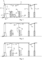
- Figs 1-7 schematically show a power cable measurement system in different states of operation.
- Fig. 1 shows an example of a power cable measurement system 1.
- the power cable measurement system 1 is designed and configured to be permanently installed in a power cable termination region, such as at an electrical substation.
- Fig. 1 shows an example of a power cable termination region, such as an electrical substation, which includes a power cable 3, a cable termination device 5, an overhead busbar 7, and a grounding device 19.
- the power cable 3, the cable termination device 5, the power cable measurement system 1 and the grounding device 19 form a termination system 2.
- the power cable 3 is connected to the cable termination device 5, which terminates the power cable 3 at the overhead busbar 7. To this end, an end portion of the power cable 3, in particular an end portion of its conductor is received by and electrically connected to the cable termination device 5.
- the cable termination device 5 is electrically connected to the overhead busbar 7.
- the connection between the cable termination device 5 and the overhead busbar 7 is referred to as the connection point 9.
- the connection point 9 may for example be formed by a cylindrical round bolt or a connection plate with bolt openings, for enabling connection of the cable termination device 5 to the overhead busbar 7.
- the overhead busbar 7 is arranged above ground. In the example shown in Fig. 1 , the overhead busbar 7 is supported by support insulators 11.
- a disconnector 13 is configured to disconnect the power cable 3 from the electrical substation.
- the power cable measurement system 1 comprises a base structure 14, and a first movable structure 17.
- the first movable structure 7 may be movably attached to the base structure 14.
- the base structure 14 may be configured to be permanently attached or fixedly mounted to a support surface/permanent support surface 16 such as the ground.
- the first movable structure 17 may for example comprise one or more arms, levers, and/or a linkage.
- the first movable structure 17 may for example have a similar design to a knife switch.
- the first movable structure 17 has a first busbar connector 15.
- the first busbar connector 15 may be attached to or be integral with the first movable structure 17.
- the first busbar connector 15 is configured to be electrically isolated from ground.
- the first busbar connector 15 is preferably provided in an end region of the first movable structure 17.
- the first busbar connector 15 is configured to be connected to and configured to be disconnected from the overhead busbar 7.
- the first movable structure 17 is configured to be moved between a default lowered position relative to the base structure 14 in which the first busbar connector 15 is disconnected from the overhead busbar 7, as shown in Fig.
- the first movable structure 17 may for example be configured to be moved by means of rotation or linear movement between the default lowered position and the temporary elevated position.
- the power cable measurement system 1 comprises a motor (not shown) configured to actuate the first movable structure 17.
- the motor is configured to move the first movable structure 17 between the default lowered position and the elevated position.
- the power cable measurement system could comprise manual mechanical means for actuating the first movable structure.
- the power cable measurement system 1 furthermore comprises a measurement equipment connector device 18.
- the measurement equipment connector device 18 is preferably configured to be installed stationarily relative to the first movable structure 17.
- the first movable structure 17 is hence configured to move relative to the measurement equipment connector device 18 when moved between the default lowered position and the elevated position.
- the first movable structure 17 is configured to be set in the elevated position only temporarily to provide an electrical connection between the overhead busbar 7 and the measurement equipment connector device 18.
- the measurement equipment connector device 18 has a measurement equipment connector 20, which may include one or more sockets or electrical connection points.
- the measurement equipment connector 20 is configured to be electrically connected to the first busbar connector 15.
- the measurement equipment connector 20 is configured to be connected to measurement equipment.
- Such measurement equipment are devices suitable for cable fault localisation, such as Time-domain reflectometry devices, Wheatstone bridges, failure burn down devices etc.
- the grounding device 19 comprises a second movable structure 21.
- the second movable structure 21 may for example comprise one or more arms, levers, and/or a linkage.
- the second movable structure 23 may for example have a similar design to a knife switch.
- the second movable structure 21 has a second busbar connector 23.
- the second busbar connector 23 may be attached to or be integral with the second movable structure 21.
- the second busbar connector 23 is preferably provided in an end region of the second movable structure 21.
- the second busbar connector 23 is configured to be connected to and configured to be disconnected from the overhead busbar 7.
- the second movable structure 21 is configured to be moved between a non-grounding position in which the second busbar connector 23 is disconnected from the overhead busbar 7, as shown in Fig. 1 , and a grounding position in which the second busbar connector 23 is electrically connected to the overhead busbar 7.
- the second busbar connector 23 is electrically connected to the overhead busbar 7, the overhead busbar 7 and
- the power cable measurement system 1 may comprise a motor (not shown) configured to actuate the second movable structure 21.
- This motor may be the same motor as the one which is configured to actuate the first movable structure 17, or it may be a different motor.
- the motor may in particular be configured to move the second movable structure 21 between the non-grounding position and the grounding position.
- the power cable measurement system could comprise manual mechanical means for actuating the second movable structure.
- the power cable measurement system 1 may comprise a first busbar contact device 27.
- the first busbar contact device 27 may be configured to be attached to the overhead busbar 7 or to the connection point 9 between the cable termination device 5 and the overhead busbar 7.
- the first busbar contact device 27 may be configured to be permanently attached to the overhead busbar 7 or to the connection point 9 between the cable termination device 5 and the overhead busbar 7.
- the first busbar contact device 27 is configured to be connected to the first busbar connector 15.
- the first busbar contact device 27 is designed to ensure a reliable electrical connection between the overhead busbar 7 and the first busbar connector 15.
- the power cable measurement system 1 may comprise a second busbar contact device 29.
- the second busbar contact device 29 may be configured to be attached to the overhead busbar 7 or to the connection point 9 between the cable termination device 5 and the overhead busbar 7.
- the second busbar contact device 29 may be configured to be permanently attached to the overhead busbar 7 or to the connection point 9 between the cable termination device 5 and the overhead busbar 7.
- the second busbar contact device 29 is configured to be connected to the second busbar connector 23.
- the second busbar contact device 29 is designed to ensure a reliable electrical connection between the overhead busbar 7 and the second busbar connector 23.
- Fig. 1 illustrates a state in which the disconnector 13 is opened in order to de-energise the overhead busbar 7 and perform measurements to locate any fault along the power cable 3.
- the overhead busbar 7 is hence electrically isolated from the rest of the substation.
- the power cable 3 is hence disconnected from the substation.
- the power cable 3 is connected to ground in a step b), as shown in Fig. 2 .
- the grounding device 19 is manoeuvred from the non-grounding position shown in Fig. 1 to a grounding position in which the second busbar connector 23 is connected to the second busbar contact device 29.
- the overhead busbar 7 which is electrically isolated from the substation hence becomes connected to ground.
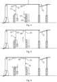
- the first movable structure 17 is manoeuvred from the default lowered position shown in Figs 1 and 2 to the elevated position in a step c).
- the first busbar connector 15 is connected to the first busbar contact device 27.
- the grounding device 19 is maintained in the grounding position.
- the disconnector 13 is maintained in the open position.
- Measurement equipment may now in a step d) be connected to the measurement equipment connector device 20. Without the first movable structure 17 and the busbar contact device 27, the operator would have to wait for availability of an elevated work platform, operators for the platform, good weather, etc.
- the grounding device 19 is moved from the grounding position to the non-grounding position in a step e).
- the second busbar connector 23 is hence disconnected from the second busbar contact device 29.
- the overhead busbar 7 and hence the power cable 3 are no longer grounded by means of the grounding device 19. Measurements may in this state be conducted to locate a fault.
- the disconnector 13 is maintained in the open position.
- the grounding device 19 is moved from the non-grounding position to the grounding position in a step f).
- the second busbar connector 23 is hence connected to the second busbar contact device 29.
- Step f) is preferably performed after the measurements have been completed.
- the power cable 3 is hence again grounded.
- the disconnector 13 is maintained in the open position.
- the first movable structure 17 is maintained in the elevated position until the grounding device 19 has reached the grounding position.
- the first busbar connector 15 is hence maintained connected to the first busbar contact device 27.
- the first movable structure 17 is manoeuvred from the elevated position to the default lowered position in a step g).
- the first busbar connector 15 is hence disconnected from the first busbar contact device 27.
- the grounding device 19 is maintained in the grounding position during this time.
- the second busbar connector 23 is hence connected to the second busbar contact device 29.
- the disconnector 13 is maintained in the open position.
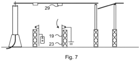
- Fig. 7 shows a step h) in which the grounding device 19 is moved from the grounding position to the non-grounding position.
- the second busbar connector 23 is hence disconnected from the second busbar contact device 29.
- Step h) is typically performed once the fault has been addressed and the power cable 3 is again fully operational.
- a respective power cable measurement system 1 may be installed at each power cable termination of a substation.
Landscapes
- Physics & Mathematics (AREA)
- General Physics & Mathematics (AREA)
- Locating Faults (AREA)
Priority Applications (7)
| Application Number | Priority Date | Filing Date | Title |
|---|---|---|---|
| EP18205158.1A EP3650871B1 (en) | 2018-11-08 | 2018-11-08 | Power cable measurement system |
| DK18205158.1T DK3650871T3 (da) | 2018-11-08 | 2018-11-08 | Strømkabelmålesystem |
| PL18205158.1T PL3650871T3 (pl) | 2018-11-08 | 2018-11-08 | System pomiaru kabla zasilającego |
| PCT/EP2019/080380 WO2020094710A1 (en) | 2018-11-08 | 2019-11-06 | Power cable measurement system |
| AU2019374406A AU2019374406B2 (en) | 2018-11-08 | 2019-11-06 | Power cable measurement system |
| US17/281,875 US11467224B2 (en) | 2018-11-08 | 2019-11-06 | Power cable measurement system |
| CA3118050A CA3118050A1 (en) | 2018-11-08 | 2019-11-06 | Power cable measurement system |
Applications Claiming Priority (1)
| Application Number | Priority Date | Filing Date | Title |
|---|---|---|---|
| EP18205158.1A EP3650871B1 (en) | 2018-11-08 | 2018-11-08 | Power cable measurement system |
Publications (2)
| Publication Number | Publication Date |
|---|---|
| EP3650871A1 EP3650871A1 (en) | 2020-05-13 |
| EP3650871B1 true EP3650871B1 (en) | 2023-12-13 |
Family
ID=64267659
Family Applications (1)
| Application Number | Title | Priority Date | Filing Date |
|---|---|---|---|
| EP18205158.1A Active EP3650871B1 (en) | 2018-11-08 | 2018-11-08 | Power cable measurement system |
Country Status (7)
| Country | Link |
|---|---|
| US (1) | US11467224B2 (pl) |
| EP (1) | EP3650871B1 (pl) |
| AU (1) | AU2019374406B2 (pl) |
| CA (1) | CA3118050A1 (pl) |
| DK (1) | DK3650871T3 (pl) |
| PL (1) | PL3650871T3 (pl) |
| WO (1) | WO2020094710A1 (pl) |
Citations (1)
| Publication number | Priority date | Publication date | Assignee | Title |
|---|---|---|---|---|
| EP1101262B1 (en) * | 1999-05-27 | 2014-03-05 | ABB S.p.A. | Electric substation |
Family Cites Families (10)
| Publication number | Priority date | Publication date | Assignee | Title |
|---|---|---|---|---|
| JPS5688606A (en) * | 1979-12-20 | 1981-07-18 | Tokyo Shibaura Electric Co | Gas insulation grounding unit |
| JPS62221807A (ja) * | 1986-03-20 | 1987-09-29 | 日本碍子株式会社 | 変電所における受電方式 |
| JPH06225448A (ja) * | 1992-12-04 | 1994-08-12 | Fuji Electric Co Ltd | 母線保護方法 |
| JPH07270473A (ja) * | 1994-03-29 | 1995-10-20 | Kansai Electric Power Co Inc:The | 母線事故の診断方法及び診断装置 |
| GB2331412B (en) * | 1997-11-18 | 2001-11-28 | Nat Grid Company Plc | A substation |
| CA2620970A1 (fr) * | 2008-01-31 | 2009-07-31 | Andre Lessard | Manipulateur portable pour effectuer des travaux sur des lignes electriques aeriennes sous tension |
| KR101155106B1 (ko) * | 2010-08-09 | 2012-06-12 | 한국전력공사 | 접지 검출 시스템 및 방법 |
| KR101809827B1 (ko) * | 2016-04-01 | 2017-12-15 | 엘에스산전 주식회사 | 계측기 |
| WO2018064754A1 (en) * | 2016-10-05 | 2018-04-12 | Hydro-Quebec | Resistance-measuring device and method |
| CN108092142B (zh) * | 2017-11-28 | 2020-07-17 | 国网河南省电力公司修武县供电公司 | 一种针对高压开关柜的结构 |
-
2018
- 2018-11-08 PL PL18205158.1T patent/PL3650871T3/pl unknown
- 2018-11-08 DK DK18205158.1T patent/DK3650871T3/da active
- 2018-11-08 EP EP18205158.1A patent/EP3650871B1/en active Active
-
2019
- 2019-11-06 AU AU2019374406A patent/AU2019374406B2/en active Active
- 2019-11-06 CA CA3118050A patent/CA3118050A1/en active Pending
- 2019-11-06 US US17/281,875 patent/US11467224B2/en active Active
- 2019-11-06 WO PCT/EP2019/080380 patent/WO2020094710A1/en not_active Ceased
Patent Citations (1)
| Publication number | Priority date | Publication date | Assignee | Title |
|---|---|---|---|---|
| EP1101262B1 (en) * | 1999-05-27 | 2014-03-05 | ABB S.p.A. | Electric substation |
Also Published As
| Publication number | Publication date |
|---|---|
| PL3650871T3 (pl) | 2024-09-02 |
| US11467224B2 (en) | 2022-10-11 |
| AU2019374406A1 (en) | 2021-06-10 |
| WO2020094710A1 (en) | 2020-05-14 |
| EP3650871A1 (en) | 2020-05-13 |
| US20220011380A1 (en) | 2022-01-13 |
| AU2019374406B2 (en) | 2024-05-23 |
| CA3118050A1 (en) | 2020-05-14 |
| DK3650871T3 (da) | 2024-02-26 |
Similar Documents
| Publication | Publication Date | Title |
|---|---|---|
| CN102763294B (zh) | 使电气装备集成在结构上的系统及其电气装备的隔离方法 | |
| US10748728B2 (en) | Boom mountable breaker and methods of using same | |
| WO2012119194A1 (en) | Solar cell installation. cut-out switch and method | |
| CN108808556A (zh) | 一种用于配电线路检修的验电接地一体化装置 | |
| KR102147981B1 (ko) | 배전선로 고장구간 자동 검출 개폐설비 | |
| KR101483492B1 (ko) | 지중 매설용 절연형 배전반 | |
| US9966207B1 (en) | Motorized high voltage in-line disconnect switch with communication system controls | |
| EP4046249B1 (en) | High voltage overhead electric transmission line equipped with switchgear unit | |
| EP3650871B1 (en) | Power cable measurement system | |
| JP5442675B2 (ja) | 絶縁抵抗測定システム | |
| US11677233B2 (en) | Smart bus plug remote actuation, monitoring, and control | |
| KR101011002B1 (ko) | 가스절연기기 | |
| US11894207B2 (en) | Smart bus plug remote actuation, monitoring, and control | |
| GB2627946A (en) | Isolating switch for electric railway or tramway | |
| CN206697410U (zh) | 一种柱上真空负荷开关 | |
| EP4047763A1 (en) | Electrical switchgear for electric power generation installations | |
| SU1269221A1 (ru) | Способ ремонта под напр жением высоковольтной аппаратуры | |
| JP3912757B2 (ja) | 断路器用動力操作装置の故障診断方法 | |
| IT201900018803A1 (it) | Palo, particolarmente per una linea di trasmissione elettrica aerea ad alta tensione, dotato di unità di manovra e relativo Sistema di Protezione, Comando e Controllo | |
| Rego et al. | Application of high voltage (HV) live-line working techniques-Hot stick in HV/MV substation maintenance-A case study | |
| Gemme et al. | Installed base modernization and monitoring solution at Petrochemical Company | |
| CN117059425A (zh) | 可调式接地刀闸装置 | |
| EP1420426A1 (en) | Operating device for simultaneous disconnecting switch | |
| Raux et al. | Remote controlled overhead switchgear in association with fault indicator-M2S |
Legal Events
| Date | Code | Title | Description |
|---|---|---|---|
| PUAI | Public reference made under article 153(3) epc to a published international application that has entered the european phase |
Free format text: ORIGINAL CODE: 0009012 |
|
| STAA | Information on the status of an ep patent application or granted ep patent |
Free format text: STATUS: THE APPLICATION HAS BEEN PUBLISHED |
|
| AK | Designated contracting states |
Kind code of ref document: A1 Designated state(s): AL AT BE BG CH CY CZ DE DK EE ES FI FR GB GR HR HU IE IS IT LI LT LU LV MC MK MT NL NO PL PT RO RS SE SI SK SM TR |
|
| AX | Request for extension of the european patent |
Extension state: BA ME |
|
| STAA | Information on the status of an ep patent application or granted ep patent |
Free format text: STATUS: REQUEST FOR EXAMINATION WAS MADE |
|
| 17P | Request for examination filed |
Effective date: 20201113 |
|
| RBV | Designated contracting states (corrected) |
Designated state(s): AL AT BE BG CH CY CZ DE DK EE ES FI FR GB GR HR HU IE IS IT LI LT LU LV MC MK MT NL NO PL PT RO RS SE SI SK SM TR |
|
| STAA | Information on the status of an ep patent application or granted ep patent |
Free format text: STATUS: EXAMINATION IS IN PROGRESS |
|
| 17Q | First examination report despatched |
Effective date: 20221020 |
|
| REG | Reference to a national code |
Ref country code: DE Ref legal event code: R079 Free format text: PREVIOUS MAIN CLASS: G01R0031020000 Ipc: G01R0031500000 Ref country code: DE Ref legal event code: R079 Ref document number: 602018062513 Country of ref document: DE Free format text: PREVIOUS MAIN CLASS: G01R0031020000 Ipc: G01R0031500000 |
|
| GRAP | Despatch of communication of intention to grant a patent |
Free format text: ORIGINAL CODE: EPIDOSNIGR1 |
|
| STAA | Information on the status of an ep patent application or granted ep patent |
Free format text: STATUS: GRANT OF PATENT IS INTENDED |
|
| RIC1 | Information provided on ipc code assigned before grant |
Ipc: G01R 31/50 20200101AFI20230606BHEP |
|
| INTG | Intention to grant announced |
Effective date: 20230710 |
|
| GRAS | Grant fee paid |
Free format text: ORIGINAL CODE: EPIDOSNIGR3 |
|
| GRAA | (expected) grant |
Free format text: ORIGINAL CODE: 0009210 |
|
| STAA | Information on the status of an ep patent application or granted ep patent |
Free format text: STATUS: THE PATENT HAS BEEN GRANTED |
|
| AK | Designated contracting states |
Kind code of ref document: B1 Designated state(s): AL AT BE BG CH CY CZ DE DK EE ES FI FR GB GR HR HU IE IS IT LI LT LU LV MC MK MT NL NO PL PT RO RS SE SI SK SM TR |
|
| REG | Reference to a national code |
Ref country code: GB Ref legal event code: FG4D |
|
| REG | Reference to a national code |
Ref country code: CH Ref legal event code: EP |
|
| P01 | Opt-out of the competence of the unified patent court (upc) registered |
Effective date: 20231113 |
|
| REG | Reference to a national code |
Ref country code: DE Ref legal event code: R096 Ref document number: 602018062513 Country of ref document: DE |
|
| REG | Reference to a national code |
Ref country code: IE Ref legal event code: FG4D |
|
| REG | Reference to a national code |
Ref country code: DK Ref legal event code: T3 Effective date: 20240222 |
|
| REG | Reference to a national code |
Ref country code: NL Ref legal event code: FP |
|
| REG | Reference to a national code |
Ref country code: SE Ref legal event code: TRGR |
|
| PG25 | Lapsed in a contracting state [announced via postgrant information from national office to epo] |
Ref country code: GR Free format text: LAPSE BECAUSE OF FAILURE TO SUBMIT A TRANSLATION OF THE DESCRIPTION OR TO PAY THE FEE WITHIN THE PRESCRIBED TIME-LIMIT Effective date: 20240314 |
|
| REG | Reference to a national code |
Ref country code: LT Ref legal event code: MG9D |
|
| PG25 | Lapsed in a contracting state [announced via postgrant information from national office to epo] |
Ref country code: LT Free format text: LAPSE BECAUSE OF FAILURE TO SUBMIT A TRANSLATION OF THE DESCRIPTION OR TO PAY THE FEE WITHIN THE PRESCRIBED TIME-LIMIT Effective date: 20231213 |
|
| PG25 | Lapsed in a contracting state [announced via postgrant information from national office to epo] |
Ref country code: ES Free format text: LAPSE BECAUSE OF FAILURE TO SUBMIT A TRANSLATION OF THE DESCRIPTION OR TO PAY THE FEE WITHIN THE PRESCRIBED TIME-LIMIT Effective date: 20231213 |
|
| PG25 | Lapsed in a contracting state [announced via postgrant information from national office to epo] |
Ref country code: LT Free format text: LAPSE BECAUSE OF FAILURE TO SUBMIT A TRANSLATION OF THE DESCRIPTION OR TO PAY THE FEE WITHIN THE PRESCRIBED TIME-LIMIT Effective date: 20231213 Ref country code: GR Free format text: LAPSE BECAUSE OF FAILURE TO SUBMIT A TRANSLATION OF THE DESCRIPTION OR TO PAY THE FEE WITHIN THE PRESCRIBED TIME-LIMIT Effective date: 20240314 Ref country code: ES Free format text: LAPSE BECAUSE OF FAILURE TO SUBMIT A TRANSLATION OF THE DESCRIPTION OR TO PAY THE FEE WITHIN THE PRESCRIBED TIME-LIMIT Effective date: 20231213 Ref country code: BG Free format text: LAPSE BECAUSE OF FAILURE TO SUBMIT A TRANSLATION OF THE DESCRIPTION OR TO PAY THE FEE WITHIN THE PRESCRIBED TIME-LIMIT Effective date: 20240313 |
|
| REG | Reference to a national code |
Ref country code: AT Ref legal event code: MK05 Ref document number: 1640882 Country of ref document: AT Kind code of ref document: T Effective date: 20231213 |
|
| PG25 | Lapsed in a contracting state [announced via postgrant information from national office to epo] |
Ref country code: RS Free format text: LAPSE BECAUSE OF FAILURE TO SUBMIT A TRANSLATION OF THE DESCRIPTION OR TO PAY THE FEE WITHIN THE PRESCRIBED TIME-LIMIT Effective date: 20231213 Ref country code: LV Free format text: LAPSE BECAUSE OF FAILURE TO SUBMIT A TRANSLATION OF THE DESCRIPTION OR TO PAY THE FEE WITHIN THE PRESCRIBED TIME-LIMIT Effective date: 20231213 Ref country code: HR Free format text: LAPSE BECAUSE OF FAILURE TO SUBMIT A TRANSLATION OF THE DESCRIPTION OR TO PAY THE FEE WITHIN THE PRESCRIBED TIME-LIMIT Effective date: 20231213 |
|
| PG25 | Lapsed in a contracting state [announced via postgrant information from national office to epo] |
Ref country code: IS Free format text: LAPSE BECAUSE OF FAILURE TO SUBMIT A TRANSLATION OF THE DESCRIPTION OR TO PAY THE FEE WITHIN THE PRESCRIBED TIME-LIMIT Effective date: 20240413 |
|
| PG25 | Lapsed in a contracting state [announced via postgrant information from national office to epo] |
Ref country code: AT Free format text: LAPSE BECAUSE OF FAILURE TO SUBMIT A TRANSLATION OF THE DESCRIPTION OR TO PAY THE FEE WITHIN THE PRESCRIBED TIME-LIMIT Effective date: 20231213 Ref country code: CZ Free format text: LAPSE BECAUSE OF FAILURE TO SUBMIT A TRANSLATION OF THE DESCRIPTION OR TO PAY THE FEE WITHIN THE PRESCRIBED TIME-LIMIT Effective date: 20231213 |
|
| PG25 | Lapsed in a contracting state [announced via postgrant information from national office to epo] |
Ref country code: SK Free format text: LAPSE BECAUSE OF FAILURE TO SUBMIT A TRANSLATION OF THE DESCRIPTION OR TO PAY THE FEE WITHIN THE PRESCRIBED TIME-LIMIT Effective date: 20231213 |
|
| PG25 | Lapsed in a contracting state [announced via postgrant information from national office to epo] |
Ref country code: SM Free format text: LAPSE BECAUSE OF FAILURE TO SUBMIT A TRANSLATION OF THE DESCRIPTION OR TO PAY THE FEE WITHIN THE PRESCRIBED TIME-LIMIT Effective date: 20231213 Ref country code: SK Free format text: LAPSE BECAUSE OF FAILURE TO SUBMIT A TRANSLATION OF THE DESCRIPTION OR TO PAY THE FEE WITHIN THE PRESCRIBED TIME-LIMIT Effective date: 20231213 Ref country code: RO Free format text: LAPSE BECAUSE OF FAILURE TO SUBMIT A TRANSLATION OF THE DESCRIPTION OR TO PAY THE FEE WITHIN THE PRESCRIBED TIME-LIMIT Effective date: 20231213 Ref country code: IT Free format text: LAPSE BECAUSE OF FAILURE TO SUBMIT A TRANSLATION OF THE DESCRIPTION OR TO PAY THE FEE WITHIN THE PRESCRIBED TIME-LIMIT Effective date: 20231213 Ref country code: IS Free format text: LAPSE BECAUSE OF FAILURE TO SUBMIT A TRANSLATION OF THE DESCRIPTION OR TO PAY THE FEE WITHIN THE PRESCRIBED TIME-LIMIT Effective date: 20240413 Ref country code: EE Free format text: LAPSE BECAUSE OF FAILURE TO SUBMIT A TRANSLATION OF THE DESCRIPTION OR TO PAY THE FEE WITHIN THE PRESCRIBED TIME-LIMIT Effective date: 20231213 Ref country code: CZ Free format text: LAPSE BECAUSE OF FAILURE TO SUBMIT A TRANSLATION OF THE DESCRIPTION OR TO PAY THE FEE WITHIN THE PRESCRIBED TIME-LIMIT Effective date: 20231213 Ref country code: AT Free format text: LAPSE BECAUSE OF FAILURE TO SUBMIT A TRANSLATION OF THE DESCRIPTION OR TO PAY THE FEE WITHIN THE PRESCRIBED TIME-LIMIT Effective date: 20231213 |
|
| PG25 | Lapsed in a contracting state [announced via postgrant information from national office to epo] |
Ref country code: PT Free format text: LAPSE BECAUSE OF FAILURE TO SUBMIT A TRANSLATION OF THE DESCRIPTION OR TO PAY THE FEE WITHIN THE PRESCRIBED TIME-LIMIT Effective date: 20240415 |
|
| PG25 | Lapsed in a contracting state [announced via postgrant information from national office to epo] |
Ref country code: PT Free format text: LAPSE BECAUSE OF FAILURE TO SUBMIT A TRANSLATION OF THE DESCRIPTION OR TO PAY THE FEE WITHIN THE PRESCRIBED TIME-LIMIT Effective date: 20240415 |
|
| REG | Reference to a national code |
Ref country code: DE Ref legal event code: R097 Ref document number: 602018062513 Country of ref document: DE |
|
| PLBE | No opposition filed within time limit |
Free format text: ORIGINAL CODE: 0009261 |
|
| STAA | Information on the status of an ep patent application or granted ep patent |
Free format text: STATUS: NO OPPOSITION FILED WITHIN TIME LIMIT |
|
| PG25 | Lapsed in a contracting state [announced via postgrant information from national office to epo] |
Ref country code: SI Free format text: LAPSE BECAUSE OF FAILURE TO SUBMIT A TRANSLATION OF THE DESCRIPTION OR TO PAY THE FEE WITHIN THE PRESCRIBED TIME-LIMIT Effective date: 20231213 |
|
| PG25 | Lapsed in a contracting state [announced via postgrant information from national office to epo] |
Ref country code: SI Free format text: LAPSE BECAUSE OF FAILURE TO SUBMIT A TRANSLATION OF THE DESCRIPTION OR TO PAY THE FEE WITHIN THE PRESCRIBED TIME-LIMIT Effective date: 20231213 |
|
| 26N | No opposition filed |
Effective date: 20240916 |
|
| REG | Reference to a national code |
Ref country code: CH Ref legal event code: PL |
|
| PG25 | Lapsed in a contracting state [announced via postgrant information from national office to epo] |
Ref country code: MC Free format text: LAPSE BECAUSE OF FAILURE TO SUBMIT A TRANSLATION OF THE DESCRIPTION OR TO PAY THE FEE WITHIN THE PRESCRIBED TIME-LIMIT Effective date: 20231213 |
|
| PG25 | Lapsed in a contracting state [announced via postgrant information from national office to epo] |
Ref country code: LU Free format text: LAPSE BECAUSE OF NON-PAYMENT OF DUE FEES Effective date: 20241108 |
|
| REG | Reference to a national code |
Ref country code: CH Ref legal event code: PL |
|
| PG25 | Lapsed in a contracting state [announced via postgrant information from national office to epo] |
Ref country code: CH Free format text: LAPSE BECAUSE OF NON-PAYMENT OF DUE FEES Effective date: 20241130 |
|
| REG | Reference to a national code |
Ref country code: BE Ref legal event code: MM Effective date: 20241130 |
|
| PG25 | Lapsed in a contracting state [announced via postgrant information from national office to epo] |
Ref country code: FI Free format text: LAPSE BECAUSE OF FAILURE TO SUBMIT A TRANSLATION OF THE DESCRIPTION OR TO PAY THE FEE WITHIN THE PRESCRIBED TIME-LIMIT Effective date: 20231213 |
|
| PG25 | Lapsed in a contracting state [announced via postgrant information from national office to epo] |
Ref country code: BE Free format text: LAPSE BECAUSE OF NON-PAYMENT OF DUE FEES Effective date: 20241130 |
|
| PG25 | Lapsed in a contracting state [announced via postgrant information from national office to epo] |
Ref country code: IE Free format text: LAPSE BECAUSE OF NON-PAYMENT OF DUE FEES Effective date: 20241108 |
|
| PGFP | Annual fee paid to national office [announced via postgrant information from national office to epo] |
Ref country code: NL Payment date: 20251121 Year of fee payment: 8 |
|
| PGFP | Annual fee paid to national office [announced via postgrant information from national office to epo] |
Ref country code: DE Payment date: 20251118 Year of fee payment: 8 |
|
| PGFP | Annual fee paid to national office [announced via postgrant information from national office to epo] |
Ref country code: GB Payment date: 20251117 Year of fee payment: 8 |
|
| PGFP | Annual fee paid to national office [announced via postgrant information from national office to epo] |
Ref country code: NO Payment date: 20251120 Year of fee payment: 8 |
|
| PGFP | Annual fee paid to national office [announced via postgrant information from national office to epo] |
Ref country code: DK Payment date: 20251120 Year of fee payment: 8 |
|
| PGFP | Annual fee paid to national office [announced via postgrant information from national office to epo] |
Ref country code: FR Payment date: 20251117 Year of fee payment: 8 |
|
| PGFP | Annual fee paid to national office [announced via postgrant information from national office to epo] |
Ref country code: SE Payment date: 20251121 Year of fee payment: 8 |
|
| PGFP | Annual fee paid to national office [announced via postgrant information from national office to epo] |
Ref country code: PL Payment date: 20251010 Year of fee payment: 8 |