EP3650825B1 - Mesure de la force operationnelle d'une composante mecanique - Google Patents
Mesure de la force operationnelle d'une composante mecanique Download PDFInfo
- Publication number
- EP3650825B1 EP3650825B1 EP18205415.5A EP18205415A EP3650825B1 EP 3650825 B1 EP3650825 B1 EP 3650825B1 EP 18205415 A EP18205415 A EP 18205415A EP 3650825 B1 EP3650825 B1 EP 3650825B1
- Authority
- EP
- European Patent Office
- Prior art keywords
- piezoelectric coefficient
- strain
- web
- coefficient axis
- measuring sensors
- Prior art date
- Legal status (The legal status is an assumption and is not a legal conclusion. Google has not performed a legal analysis and makes no representation as to the accuracy of the status listed.)
- Active
Links
- 238000005259 measurement Methods 0.000 title description 35
- 238000000034 method Methods 0.000 claims description 12
- 239000000463 material Substances 0.000 claims description 10
- 238000005476 soldering Methods 0.000 claims description 5
- 229910000639 Spring steel Inorganic materials 0.000 claims description 4
- 229910000881 Cu alloy Inorganic materials 0.000 claims description 3
- 239000000919 ceramic Substances 0.000 claims 1
- 238000013461 design Methods 0.000 description 8
- 230000000694 effects Effects 0.000 description 7
- 229910000679 solder Inorganic materials 0.000 description 6
- 238000009826 distribution Methods 0.000 description 5
- 239000011888 foil Substances 0.000 description 5
- 239000002184 metal Substances 0.000 description 4
- 229910052751 metal Inorganic materials 0.000 description 4
- 238000004026 adhesive bonding Methods 0.000 description 2
- 230000001419 dependent effect Effects 0.000 description 2
- 238000010586 diagram Methods 0.000 description 2
- 238000004049 embossing Methods 0.000 description 2
- 238000005516 engineering process Methods 0.000 description 2
- 238000001914 filtration Methods 0.000 description 2
- 239000011521 glass Substances 0.000 description 2
- 238000005304 joining Methods 0.000 description 2
- 239000002655 kraft paper Substances 0.000 description 2
- 238000012986 modification Methods 0.000 description 2
- 230000004048 modification Effects 0.000 description 2
- 238000009420 retrofitting Methods 0.000 description 2
- 230000035945 sensitivity Effects 0.000 description 2
- 230000011664 signaling Effects 0.000 description 2
- RYGMFSIKBFXOCR-UHFFFAOYSA-N Copper Chemical compound [Cu] RYGMFSIKBFXOCR-UHFFFAOYSA-N 0.000 description 1
- XUIMIQQOPSSXEZ-UHFFFAOYSA-N Silicon Chemical compound [Si] XUIMIQQOPSSXEZ-UHFFFAOYSA-N 0.000 description 1
- 239000000853 adhesive Substances 0.000 description 1
- 230000001070 adhesive effect Effects 0.000 description 1
- 238000005452 bending Methods 0.000 description 1
- 230000015572 biosynthetic process Effects 0.000 description 1
- 238000010276 construction Methods 0.000 description 1
- 229910052802 copper Inorganic materials 0.000 description 1
- 239000010949 copper Substances 0.000 description 1
- 230000003247 decreasing effect Effects 0.000 description 1
- 238000011161 development Methods 0.000 description 1
- 230000018109 developmental process Effects 0.000 description 1
- 230000002349 favourable effect Effects 0.000 description 1
- 238000009434 installation Methods 0.000 description 1
- 230000007774 longterm Effects 0.000 description 1
- 238000003754 machining Methods 0.000 description 1
- 238000004519 manufacturing process Methods 0.000 description 1
- 150000002736 metal compounds Chemical class 0.000 description 1
- 238000003801 milling Methods 0.000 description 1
- 238000012544 monitoring process Methods 0.000 description 1
- 230000036316 preload Effects 0.000 description 1
- 230000000717 retained effect Effects 0.000 description 1
- 230000008054 signal transmission Effects 0.000 description 1
- 229910052710 silicon Inorganic materials 0.000 description 1
- 239000010703 silicon Substances 0.000 description 1
- 238000004088 simulation Methods 0.000 description 1
Images


Classifications
-
- G—PHYSICS
- G01—MEASURING; TESTING
- G01L—MEASURING FORCE, STRESS, TORQUE, WORK, MECHANICAL POWER, MECHANICAL EFFICIENCY, OR FLUID PRESSURE
- G01L5/00—Apparatus for, or methods of, measuring force, work, mechanical power, or torque, specially adapted for specific purposes
- G01L5/16—Apparatus for, or methods of, measuring force, work, mechanical power, or torque, specially adapted for specific purposes for measuring several components of force
- G01L5/161—Apparatus for, or methods of, measuring force, work, mechanical power, or torque, specially adapted for specific purposes for measuring several components of force using variations in ohmic resistance
- G01L5/162—Apparatus for, or methods of, measuring force, work, mechanical power, or torque, specially adapted for specific purposes for measuring several components of force using variations in ohmic resistance of piezoresistors
-
- G—PHYSICS
- G01—MEASURING; TESTING
- G01L—MEASURING FORCE, STRESS, TORQUE, WORK, MECHANICAL POWER, MECHANICAL EFFICIENCY, OR FLUID PRESSURE
- G01L1/00—Measuring force or stress, in general
- G01L1/20—Measuring force or stress, in general by measuring variations in ohmic resistance of solid materials or of electrically-conductive fluids; by making use of electrokinetic cells, i.e. liquid-containing cells wherein an electrical potential is produced or varied upon the application of stress
- G01L1/22—Measuring force or stress, in general by measuring variations in ohmic resistance of solid materials or of electrically-conductive fluids; by making use of electrokinetic cells, i.e. liquid-containing cells wherein an electrical potential is produced or varied upon the application of stress using resistance strain gauges
- G01L1/2206—Special supports with preselected places to mount the resistance strain gauges; Mounting of supports
-
- G—PHYSICS
- G01—MEASURING; TESTING
- G01L—MEASURING FORCE, STRESS, TORQUE, WORK, MECHANICAL POWER, MECHANICAL EFFICIENCY, OR FLUID PRESSURE
- G01L5/00—Apparatus for, or methods of, measuring force, work, mechanical power, or torque, specially adapted for specific purposes
- G01L5/24—Apparatus for, or methods of, measuring force, work, mechanical power, or torque, specially adapted for specific purposes for determining value of torque or twisting moment for tightening a nut or other member which is similarly stressed
Definitions
- the invention relates to the operating force measurement in a mechanical component, a strain measuring sensor, which comprises at least one strain gauge (DMS) arranged in a plane and with a piezo coefficient axis, is used to detect the force perpendicular to the plane and along a mounting surface its longitudinal sides exposed, elongated web is arranged, which extends parallel to the plane, and the strain measurement sensor is firmly connected to the web.
- DMS strain gauge
- Foil strain gauges are used there to measure a torsional force in a bolt or the like.
- the foil strain gauges lie in a field delimited by two parallel longitudinal slots.
- Two groups of foil strain gauges are formed in the field. Within each group, the foil strain gauges are parallel to one another and the groups are at right angles to one another and at a 45 ° angle to the two longitudinal slots.
- a similar force measurement can be found in the US-A-4079624 .
- Mechanical components are often subjected to a force, the main direction of which is perpendicular to a plane, but which overall can be tilted with respect to the plane.
- a particularly catchy example of this are machine elements and, in this case, screws in particular.
- the load condition of a screw is characterized by the pretensioning force with which the screw head presses on the base and the operating force dependent on the operating condition.
- the main direction of the resulting force runs perpendicular to a plane to which the screw bolt axis is perpendicular. This can be shown in a so-called stress diagram.
- the diagram only takes into account a one-dimensional load on the connection along the main direction. This type of consideration is also used for dimensioning.
- the mechanical component can be very difficult to reach.
- One example are machine elements in wind power rotors, which are obviously only accessible with considerable effort.
- the at least one force component deviating from the main direction creates a two-dimensional stress distribution in the plane perpendicular to the main direction. It was therefore considered to arrange a strain measuring sensor for the measurement in a flat mounting surface that is parallel to the plane. The mounting surface is deformed by the force acting. This leads to a two-dimensional field of tension in the mounting surface.
- Silicon strain gauges are known for such strain measurement sensors, which are arranged in the strain measurement sensor as a full bridge, half bridge or quarter bridge. They are smaller and more sensitive than conventional metal-foil strain gauges. It is particularly advantageous to integrate a full bridge made up of four square Si measuring resistors in a chip. This strain measuring sensor has, for example, an area of 0.25 mm 2 and a thickness of 0.015 mm. The effect of the piezoresistive constants for the longitudinal load and the transverse load results in a full bridge with four measuring resistors arranged at right angles to one another. In a uniaxial stress state, two resistances are increased and two are decreased.
- a position of the strain measuring sensor is therefore necessary at which the greatest possible difference between the mechanical tension in the x and y directions is present in the mounting surface.
- the strain measuring sensor must then be positioned very precisely on the mounting surface, for example a screw head, since it must be in the point of maximum laterally anisotropic deformation. Otherwise transverse voltages would act, which would falsify the signal and make it unusable.
- the optimal positioning is difficult to determine, for example by means of simulations. It depends both on the direction of the force component to be measured and on the geometry of the mechanical component. In the example of the screw, this point is usually in a zone of the surface which is arranged above the bolt edge of the screw bolt. The positioning therefore depends on the size of the screw head. Depending on the dimensions and configuration of the mechanical component, for example machine element, and the direction of the force component to be measured, a different position of the strain measuring sensor is therefore required.
- the high-precision alignment of the strain measuring sensor that is required as a result increases the production effort considerably and also makes retrofitting to mechanical components already in use, for example machine elements such as screws, impossible. The latter also applies to a force measurement by interposing a pressure measuring body, as is the case, for example, in FIG DE 69311479 T2 or the DE 10217283 A1 is described.
- the invention is therefore based on the object of designing the force measurement on a mechanical component, e.g. a machine element such as a screw, in such a way that the accuracy with which the strain sensor must be positioned is reduced and at the same time also retrofitting on elements already in use becomes possible.
- the aim is to find a solution that can be used as universally as possible.
- the invention provides, on the one hand, a mechanical component, for example a machine element, which is designed to measure an operating force.
- a mechanical component for example a machine element, which is designed to measure an operating force.
- On a mounting surface of the mechanical component a longitudinally extending web that is exposed along its longitudinal sides is arranged.
- the web thus has a longitudinal direction defined by the longitudinal sides.
- the web height is optionally at least 100 ⁇ m and the web width is optionally a maximum of 2 mm.
- the web lies in a plane that defines the plane of the two-dimensional stress field. As a rule, the mounting surface also extends along this plane.
- a strain measurement sensor is attached to the bar, which comprises at least two bridge-connected Si strain gauges (DMS).
- the attachment can be done by gluing or soldering; In principle, cohesive connection techniques are preferred. Non-positive connection technology is optionally possible.
- a half bridge is present, and when using four strain gages in a square shape, there is a full bridge. Every strain gage has two coefficient axes at right angles to each other, on which a coefficient of a piezoresistive effect has a local maximum. The coefficients of the two axes differ in the sign and possibly in the maximum amount.
- the axis with the positive piezo coefficient is commonly referred to as the longitudinal axis and the other as the transverse axis.
- the strain measurement sensor is aligned to the web in such a way that the coefficient axis (or one of the two axes) lies parallel to the longitudinal direction of the web.
- One piezo coefficient axis lies parallel to the web direction, the other at right angles to it.
- one half of the strain gauges lies with its longitudinal axis parallel to the longitudinal direction, the other half with its transverse axis.
- the strain measuring sensor Since the web is exposed laterally, that is to say is not connected to the surrounding material on its longitudinal sides in the transverse direction to the web, the strain measuring sensor only detects expansions along the longitudinal direction of the web.
- the three-dimensional alignment of the web defined by the orientation of the longitudinal direction and the position of the plane, filters the stress direction, which is detected by the strain measuring sensor located on the web.
- the web has the effect of extracting a direction on the mounting surface from a two-dimensional stress distribution. Its three-dimensional alignment thus defines the direction of the force component to be measured. If you use several bars, the excellent function of known measuring bridges can be retained even when using individual strain gauges.
- the cross-sensitivity present in conventional Si-based strain measurement sensors lies transversely to the longitudinal direction of the web and therefore does not lead to a signal of a disruptive scope.
- a measurement signal is obtained that only relates to the stress in the longitudinal direction of the web.
- Care does not have to be taken to carry out an exact positioning in a place where no transverse stresses occur; d. H. the strain measuring sensor no longer has to be brought into an area in which strain occurs, if possible, only in one direction and not across it.
- the selection of the direction along which the elongation and thus the deformation is measured is determined exclusively by the plane and longitudinal direction of the web and is therefore independent of the position.
- the plane is preferably aligned perpendicular to the main direction of the operating force to be measured.
- An exposed web is understood here to mean an elongated, generally cuboid-shaped material volume, the longitudinal edges of which are not connected to adjacent material.
- a web height of 100 ⁇ m is sufficient to suppress expansion across the web's longitudinal direction.
- a thickness range of 100-500 ⁇ m is particularly preferred, and a thickness range of 200-300 ⁇ m is very particularly preferred.
- the web length is preferably at least 1 cm. Values over 2 cm are usually not required.
- the aspect ratio (length / width) is preferably at least 2 or 5 or 10 or 20.
- the web can be designed as a cuboid volume area which is firmly connected to the mounting surface, for example an upper side of the machine element.
- the bridge for example, longitudinal slots in the mounting surface, where the depth of the longitudinal slots defines the web height, embossing or machining can be considered.
- a mounting plate which has the web. This can be done by making the aforementioned longitudinal slots in the mounting plate. These slots can extend into the mounting plate as incisions. Of course, it is also possible for the longitudinal slots to be made in the mounting plate as through cuts.
- the mounting plate is already web-shaped.
- the strain measuring sensor is firmly connected to the mounting plate by a joining process, for example using a solder.
- the mounting plate is in turn firmly connected to the mounting surface.
- spring steel or a copper alloy come into consideration as the material for the mounting plate.
- the latter makes it particularly easy to solder the mounting plate to the mounting surface.
- the mounting plate can also be glued on.
- a mounting plate opens up a further aspect of the invention, namely to provide a measuring device with which mechanical components that have already been installed can be retrofitted or standard components are upgraded with regard to a measurement of the operating force.
- the only requirement is that there is a suitable mounting surface that extends along the plane mentioned.
- the exact location of the mounting location plays no or only a very subordinate role, since, unlike with a direct placement of the strain gauge, the directional filtering effect of the web on / in the mounting plate is very insensitive to the mounting position.
- the web automatically ensures the required x / y anisotropy, i.e. H. for the measurement of the elongation exclusively along the longitudinal direction of the web.
- a method for measuring an operating force in a mechanical component is also provided.
- a longitudinally extended web that is exposed along its long sides is provided on a mounting surface of the mechanical component, which has web dimensions in the stated orders of magnitude and on which the strain measurement sensor is non-positively attached in the orientation already mentioned.
- a mounting plate is provided which has the properties mentioned and the strain measurement sensor mentioned. The mounting plate is connected to the mounting surface, for example with a force fit or material fit (soldered or glued).
- the method and the mechanical component as well as the measuring device make it possible to measure the operating force currently. For example, a pre-tensioning force can be recorded. In this way, incorrect loading or even failure of a mechanical component, e.g. a screw shaking loose, can be detected at an early stage.
- a mechanical component e.g. a screw shaking loose
- At least two strain gauges are provided on webs that are at an angle to one another, preferably at a 90 ° angle.
- the inventive concept has the advantage that there is no need to intervene in the force flow of a mechanical component. Exact knowledge of the force or voltage curve is no longer necessary in order to measure an operating force in a certain direction.
- the fastening methods used can use long-term stable joining processes, such as glass frits or metal solders. Installation is simple and the design is robust. It is very particularly preferred that a single sensor can be used for a wide variety of mechanical components.
- the mechanical component e.g. a screw connection, can be monitored for life.
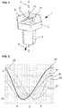
- Fig. 1 shows schematically a screw 1 with a screw head 2 and a screw bolt 3.
- the screw bolt 3 extends along a bolt axis 4, which is perpendicular to an upper side 6 and parallel to it, in the perspective view of FIG Fig. 1 underside of screw head 2 that does not appear.
- the design of a screw connection is based on a force load on the screw 1 which runs exclusively along the bolt axis 4. In the present case, however, the screw is loaded in a direction of force 8 which runs obliquely to the bolt axis 4.
- an axial component e.g. B. the preload force, which is the main direction of force, there is also a transverse force.
- the main direction of force runs perpendicular to a plane which, in turn, is perpendicular to the bolt axis 4.
- a stress distribution 10 is created in the plane in the screw head 2, symbolized by contour lines of equal stress, which run asymmetrically to mutually perpendicular main axes 12, 14, which define an x / y coordinate system of the screw head 2 plane.
- the stress distribution 10 would be completely symmetrical both to the x main axis 12 and to the y main axis 14.
- Fig. 2 shows a section through the stress distribution 10, which is shown here in a plane which is perpendicular to the bolt axis and is positioned on the surface of the screw head.
- the stress in MPa is plotted on the vertical axis and the lateral coordinate on the transverse axis.
- the zero value of the lateral coordinate corresponds to the position of the bolt axis 4.
- the zero value of the tension corresponds to a tension-free state without bending of the top 6.
- Negative tension values indicate that the tension in the representation of the Fig. 1 acts downwards, that is to say acts on the screw head 2 in a deformation which results in a depression on the upper side 6.
- Fig. 2 shows different curves that correspond to different stress states.
- the curves relate to the stress curve along the x main axis 12.
- the screw 1 under consideration is subjected to a pretensioning force along the bolt axis 4.
- Some curves show a state in which a transverse force directed parallel to the plane also acts on the underside of the bolt 3.
- Curves 24 and 22 show the application of a force of 10% of the pretensioning force, curve 22 showing the x component and curve 24 showing the y component of the mechanical stress. Curves 23 and 24 show the application of a force of 10% of the pre-tensioning force in the positive y-direction.
- a measuring device 25 is provided for the screw 1, which is shown in FIG Fig. 3 in one embodiment in plan view of the screw head 2 and in Fig. 4 in a sectional view along the line AA of Fig. 3 is shown.
- the measuring device 25 comprises a mounting plate 26, which is firmly attached to the top side 6 of the screw head 2, which serves as the mounting surface.
- the mounting plate 26 has a strain measurement sensor 28 with at least two strain gauges, preferably four strain gauges arranged as a full bridge (as described above).
- the individual resistor (s) is / are electrically contacted via contact pads, which are not designated further. Details of the possible arrangements are based on the Fig. 12-13 still explained.
- Each strain measuring sensor 28 is located on a web 30 which is delimited from the remaining material of the mounting plate 26 by incisions 32 or (not shown) severing cuts in such a way that the web is exposed on its long sides.
- the incisions 32 or severing cuts are summarized here under the term “longitudinal cuts”. They have the effect that a tension that acts transversely to the longitudinal extension of the web 30, which is referred to here as the longitudinal direction, puts the material of the mounting plate 26 under tension and, if necessary, deforms it, but not the web 30 transversely to its longitudinal extension.
- the longitudinal direction of the web and the plane in which the mounting surface is located determine the three-dimensional direction of the web.
- Fig. 3 shows two strain measuring sensors 28, 28 'on webs 30, 30' lying at right angles to one another. Accordingly, they also measure the elongation along longitudinal directions at right angles to one another. This biaxiality is optional.
- Each Si-DMS is a single resistor that has two piezoresistive coefficient axes along which the coefficient of the piezoresistive effect has a local maximum in magnitude; the Si-DMS have two coefficient axes that are at right angles to each other. They are commonly referred to as longitudinal and transverse axes, with the coefficient being positive in the longitudinal axis and negative in the transverse axis.
- the Si strain gauges are arranged in such a way that one of the two coefficient axes lies along the longitudinal direction for each individual resistance.
- the cross-sensitivity usually present in strain gauges (ie the coefficient axis perpendicular to the longitudinal direction) no longer plays a role and does not lead to a signal.
- the three-dimensional direction of the (or each) web 30 thus selects the direction along which the strain measuring sensor 28 measures the tension in the mounting plate 26 and, since this is firmly connected to the top 6 of the screw head 2, also in the screw head 2. It is no longer relevant whether the strain measuring sensor lies exactly on the bolt axis 4. Different voltage curves that, like Fig. 2 shows that the x-direction and y-direction could lead to the same voltage curve, are clearly separated. This also makes it easy to determine the direction vector of the operating force acting on the screw if at least two webs 30, 30 ', which do not extend in the same longitudinal direction, and strain sensors 28, 28' are used.
- strain measurement sensors 28 it is also not necessary for the strain measurement sensors 28 to be arranged at points on the screw head 2 at which, due to the stress pattern, there is an anisotropy in the x or. y-direction would set.
- the filtering of the direction is achieved by the formation of the web 30; the three-dimensional direction of the web defines the direction filtered with regard to the stress measurement.
- An individual adjustment of the position of the strain measuring sensor on the screw head 2 is no longer necessary. In this way, with a uniform and standardized measuring device 25, with different geometries, the operating force can be measured reliably in a precisely defined and easily selectable direction.
- the drastically reduced adjustment requirement also allows the device 25 to be retrofitted on screw heads that have already been installed.
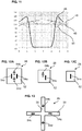
- Fig. 5 which is also a sectional view similar to the Fig. 4 is.
- Fig. 6 shows schematically a perspective view of the associated screw 1.
- recesses 36 which can be created, for example, by embossing or milling the top 6 of the screw head 2, at least one free-standing web 30 is created on the top, on which the strain sensor 28 is then attached will. Alternatively, would Longitudinal slots in the top of the screw head form the web 30, which is then also free in the mechanical sense.
- FIG. 6 shows two webs in a cross-shaped configuration, ie the web 30 is crossed by a further web 38, e.g. B. under 90 °.
- the crossed longitudinal directions make it possible to clearly select the x and y directions.
- a strain gauge can be arranged on each web 30 on one side of the bolt axis 4, and another on the opposite side. The same applies to the web 38. This allows a bridge connection of the strain gauges, which is known to be extremely advantageous in terms of signaling.
- the cross-like design of the webs 30 can also be achieved by a corresponding arrangement of the incisions 32 in a structure with a mounting plate 26.
- Fig. 7 shows, already to design the mounting plate 26 in the shape of a cross and thus to provide the webs 30, 38 on which the strain measuring sensors 28 and 40 can then be arranged.
- a strain gauge to each cross arm and to switch these four strain gauges as a full bridge. The arrangement is based on Fig. 13 explained in more detail.
- the use of a measuring device 25 with an independent mounting plate 26 allows the measuring device to be completely preconfigured.
- the strain measuring sensor 28, its electrical supply and contacting as well as the signal transmission, which can be done by radio, for example, can already be prepared on the mounting plate 26.
- the mounting plate 26 can be fastened by adhesive bonding or a soldering process, in particular using a metal solder 34 (cf. Fig. 4 ) take place. It is essential for the fastening that it transfers the stresses present in the screw head 2 to the mounting plate 26. The same applies in the event that the strain measuring sensor 28 is applied directly to a correspondingly designed top side 6 of the screw head 2. If the longitudinal cuts 32 are designed as severing cuts, it must be ensured that a metal solder does not completely fill the longitudinal cuts. This is easy to ensure by means of suitable soldering parameters and the width of the longitudinal cuts 32. If spring steel or a copper-containing metal compound is used for the mounting plate 26, the use of a metal solder is particularly simple. In general, soldering methods, glass frits or adhesives are possible for fastening the strain measuring sensor 28 on the web 30.
- the web height H is chosen so that the desired anisotropy, i.e. insensitivity to transverse stresses, is achieved.
- a value of 100 ⁇ m is usually sufficient. Particularly preferred is a value from 100 to 500 ⁇ m, very particularly preferred is from 200 to 300 ⁇ m.
- the web height H is automatically given by the thickness of the mounting plate 26.
- the height of the cross-shaped mounting plate 26 is the web height H fixed.
- the length is preferably at least 2x, 5x, 10x or 20x the width and is more preferably not less than 1 cm.
- Fig. 8 a disk-shaped element 41 on which the strain measuring sensor 28 is applied.
- the element 41 has a mounting surface 42 on which a web 30 is formed by incisions 32.
- a strain measuring sensor 28 is attached to the web 30.
- the web 30 extends along a longitudinal direction 44, here referred to as the x-direction.
- the corresponding coordinate system is in Fig. 8 entered and provides that the z-direction is perpendicular to a plane along which the web 30 extends.
- the y-direction is perpendicular to the longitudinal extension of the web 30, so that x and y span the plane of the mounting surface 42 in which the web 30 extends.
- Fig. 9 shows a sectional view which clearly shows that the web 30 is formed by incisions 32 which extend along the x-direction.
- the orientation of the element 41 in Fig. 9 corresponds to the Fig. 8 .
- FIG. 8 shows a modification in that the web 30 is delimited by cuts that cut through a thin element 43. Whether incisions or cuts are used is freely selectable and can be determined depending on the application.
- Fig. 11 shows the mechanical stresses detected by the Si strain measurement sensor 28, exemplarily in the unit MPa on the ordinate, compared to a position on the web 30.
- Curve 45 shows the stress along the y-direction, which is given for an embodiment without incisions or cuts 32 would be.
- Curve 46 shows the corresponding stresses in the x direction. As can be seen, the tensions are hardly distinguishable. This is due to the fact that conventional strain measuring sensors 28 are largely spatially isotropic with regard to the sensitivity to stresses.
- Curve 48 shows the stress in the y direction for the
- Curve 50 shows the stress in the x direction.
- the coefficient axes of the strain gauges in the strain measuring sensor 28 all extend parallel or right-angled to the longitudinal direction 44 of the web 30.
- the stresses can be clearly distinguished, since when the strain measuring sensor 28 is positioned between the locations "2" and "4", those on the abscissa in Fig. 11 are plotted, the stress in the y-direction is significantly less than in the x-direction.
- the strain measuring sensor 28 thus unambiguously measures the stress in the x-direction and has virtually no cross-sensitivity to stresses in the y-direction.
- the strain measuring sensor 28 fastened on the web 30 measures only along a preferred direction, namely the direction 44, which is achieved by the longitudinal extension of the web exposure. In the Fig. 8- 11 this is purely for the sake of example the x-direction.
- a mounting surface 42 as in Fig. 8 , 9 or 10 shown, can be provided universally. It is possible to provide them on an existing machine element or mechanical component. It is equally possible to subsequently attach a correspondingly configured component that provides the mounting surface 42 in order to measure mechanical stresses in the desired direction on an already installed component.
- the direction in which the mechanical stresses are measured is defined by the longitudinal direction 44 of the web 30.
- the term "element" is to be understood only as an example. It can be any section in a component or a structure for which the operating force is to be measured that extends essentially (but not necessarily exclusively) along the z-direction.
- the mounting surface 42 can be located inside a component that has a chamber that provides the mounting surface 42. The chamber can in particular be provided in a machine element that is loaded and for which the force is to be measured. A nut, washer, or screw would be examples.
- Figures 12A-12B show different configurations of the strain measurement sensor with different numbers or arrangements of strain gauges 54a-d.
- the strain measurement sensor 28 is designed as a chip 52 on which Si strain gauges are formed.
- the web width is twice the chip width; the web height is at least 0.2 times the chip width.
- the use of a chip 52 is optional and the arrangements of the strain gauges 54a-d in FIGS Figures 12A-12B are also possible with individual strain gauges.
- the strain gauge sensor 28 includes four strain gauges 54a-d.
- the large double arrows of the strain gauges 54a, c show how their longitudinal axis lies.
- the thin arrows of the strain gauges 54b, d show the direction of the transverse axis, and the cross lines illustrate that the longitudinal axes of the strain gauges 54b, d extend along the cross lines. Due to their inherent sensitivity, the strain gauges react along the transverse axis also on expansions, but with an inverted signal sign compared to expansions along the longitudinal axis.
- the strain gauges 54a-d are connected in a full bridge, as is known in the prior art. In this way, the signals advantageously add up both in the direction of the arrows drawn in and across it in the event of an expansion.
- the strain measurement sensor 28 is therefore largely isotropically sensitive and generates a signal in the event of expansions along the longitudinal direction of the arrows and in the event of expansions that are exactly at right angles thereto.
- the strain measuring sensor 28 is arranged on the web 30 in such a way that the coordinate axes of the strain gauges 54a-d are parallel to the longitudinal direction of the web 30. This is achieved in that the strain measurement sensor 28 is either arranged in such a way that the double arrows according to FIG Figure 12A extend parallel to the longitudinal direction or lie exactly at right angles to it.
- Figure 12B shows a variant in which two strain gauges 54a, b are connected as a half bridge in the strain measurement sensor 28, which is again embodied as a chip 52 by way of example. This is simpler in terms of structure, but not as favorable in terms of signaling as the full bridge of the Figure 12A . Otherwise, this applies to the structure of the Figure 12A Said accordingly.
- Fig. 13 shows the configuration with strain gauges 54a-d, which form a strain measurement sensor 28, on a cross-shaped web structure with a web 30 and a wide web 38 at right angles to it.
- the webs intersect here; but this is not absolutely necessary.
- Analogous to the structure of the Figure 12A lie two strain gauges 54a, c with their longitudinal axes along the longitudinal direction of one web (here the web 30) and the other two strain gauges 54b, d with their transverse axes along the web direction of the other web (here the web 38).
- the four strain gauges 54a-d are in turn connected in a full bridge, so that an increased signal results, but without a resolution of the direction.
- the crosspieces with crossed longitudinal directions make it possible to measure in two orthogonal directions and thus to determine a force vector that has a component in the z-direction.
Claims (15)
- Composant mécanique, en particulier composant de machine (2), sur lequel au moins deux capteurs de mesure d'allongement allongés (28, 40) sont fixés pour mesurer une force motrice sur une surface de montage (6, 42) et au moins une nervure allongée (30), exposée le long de ses côtés longitudinaux, est disposée sur la surface de montage (6, 42), laquelle nervure s'étend parallèlement à un plan dans lequel se trouve la surface de montage (6, 42),
caractérisé en ce que- les au moins deux capteurs de mesure d'allongement (28, 40) sont montés en pont et sont chacun conçus sous la forme d'une jauge d'allongement en Si (54a-d) qui comporte un premier axe à coefficient piézo et un deuxième axe à coefficient piézo qui est sensiblement perpendiculaire à celui-ci,- une pluralité de nervures allongées (30, 38) sont disposées sur la surface de montage (6), lesquelles s'étendent dans différentes directions longitudinales, l'un des capteurs de mesure d'allongement (28, 40) étant relié de manière fixe à chaque nervure (30, 38), et- chacun des capteurs de mesure d'allongement (28, 40) est orienté par rapport à la nervure respective (30, 38) à laquelle il est relié de sorte que-- pour l'un des capteurs de mesure d'allongement (28), le premier axe à coefficient piézo s'étend le long des côtés longitudinaux de la nervure respective (30) et le deuxième axe à coefficient piézo s'étend transversalement à ceux-ci, et-- pour l'autre des capteurs de mesure d'allongement (40), le deuxième axe à coefficient piézo s'étend le long des côtés longitudinaux de la nervure respective (38) et le premier axe à coefficient piézo s'étend transversalement à ceux-ci. - Composant mécanique selon la revendication 1, caractérisé en ce que quatre jauges d'allongement (54a-d) montées en pont complet sont prévues, le premier axe à coefficient piézo est un axe longitudinal à coefficient piézo et le deuxième axe à coefficient piézo est un axe transversal à coefficient piézo, et en ce que deux des jauges d'allongement (54a-d) ont leur axe longitudinal à coefficient piézo qui est parallèle aux côtés longitudinaux de la nervure respective (30, 38) et les deux autres jauges d'allongement en Si (54a-d) ont leur axe transversal à coefficient piézo qui est parallèle aux côtés longitudinaux de la nervure respective (30, 38).
- Composant mécanique selon la revendication 1 ou 2, caractérisé en ce qu'une plaque de montage (4), qui forme ou comporte les nervures (30, 38), est fixée sur la surface de montage (6).
- Composant mécanique selon la revendication 3, caractérisé en ce que les capteurs de mesure d'allongement (28, 40) sont soudés à la plaque de montage (4) et la plaque de montage (4) est collée ou soudée au côté supérieur (6) d'une vis de tête (2).
- Composant mécanique selon l'une des revendications 3 et 4, caractérisé en ce que la plaque de montage (4) comporte un matériau qui est adapté au matériau de la surface de montage en termes de propriétés de résistance et d'élasticité mécanique, notamment un acier à ressort, un alliage de cuivre ou une céramique.
- Composant mécanique selon l'une des revendications précédentes, caractérisé en ce que les nervures (30, 38) sont formées chacune par des incisions (8) ou des fentes longitudinales qui sont ménagées dans la surface de montage (6, 42) ou la plaque de montage (4) ou en ce que les nervures (30, 38) sont chacune conçues comme une saillie intégrale qui dépasse de la surface de montage (6).
- Composant mécanique selon l'une des revendications précédentes, caractérisé en ce que les nervures (30, 38) se croisent.
- Composant mécanique selon la revendication 7, caractérisé en ce que trois nervures (30), dont les différentes directions longitudinales font un angle de 100 à 140 degrés entre elles, sont disposées ou en ce que deux nervures (30), dont les différentes directions longitudinales forment un angle de 80 à 100 degrés entre elles, sont disposées sur une tête de vis (2).
- Dispositif de mesure destiné à mesurer une force motrice dans un composant mécanique, par exemple un composant de machine, le dispositif de mesure comportant au moins deux capteurs de mesure d'allongement allongés (28, 40) et au moins une nervure allongée (30, 38) exposée le long de ses côtés longitudinaux,
caractérisé en ce que- les au moins deux capteurs de mesure d'allongement (28, 40) sont montés en pont et sont chacun conçus sous la forme d'une jauge d'allongement en Si (54a-d) qui comporte un premier axe à coefficient piézo et un deuxième axe à coefficient piézo qui est sensiblement perpendiculaire à celui-ci,- le dispositif de mesure comporte en outre une plaque de montage (4) qui est conçue pour être reliée de manière fixe à une surface de montage (6) du composant mécanique (2) et qui comporte plusieurs nervures allongées (30, 38) qui s'étendent dans différentes directions longitudinales le long de la plaque de montage (4) et qui sont chacune conçues pour être exposées le long de leurs côtés longitudinaux, l'un des capteurs de mesure d'allongement (28, 40) étant relié de manière fixe à chaque nervure (30, 38), et- chacun des capteurs de mesure d'allongement (30, 38) est orienté par rapport à la nervure respective (30, 38) à laquelle il est relié de sorte que-- pour l'un des capteurs de mesure d'allongement (28), le premier axe à coefficient piézo s'étende le long des côtés longitudinaux de la nervure (30) et le deuxième axe à coefficient piézo s'étende transversalement à ceux-ci, et-- pour l'autre des capteurs de mesure d'allongement (40), le deuxième axe à coefficient piézo s'étende le long des côtés longitudinaux de la nervure respective (38) et le premier axe à coefficient piézo s'étende transversalement à ceux-ci. - Dispositif de mesure selon la revendication 9, caractérisé en ce que quatre jauges d'allongement (54a-d) montées en pont complet sont prévues, le premier axe à coefficient piézo est un axe longitudinal à coefficient piézo et le deuxième axe à coefficient piézo est un axe transversal à coefficient piézo, et en ce que deux des jauges d'allongement (54a-d) ont leur axe longitudinal à coefficient piézo qui est parallèle aux côtés longitudinaux de la nervure respective (30, 38) et les deux autres jauges d'allongement en Si (54a-d) ont leur axe transversal à coefficient piézo qui est parallèle aux côtés longitudinaux de la nervure respective (30, 38).
- Dispositif de mesure selon la revendication 9 ou 10, caractérisé en ce que la plaque de montage (4) est destinée à être collée ou soudée sur la surface de montage (6), la plaque de montage (4) comportant éventuellement comme matériau un acier à ressort ou un alliage de cuivre.
- Dispositif de mesure selon l'une des revendications 9 à 11, caractérisé en ce que les nervures (30, 38) se croisent.
- Procédé de mesure d'une force motrice dans un composant mécanique, par exemple un composant de machine, au moins deux capteurs de mesure d'allongement allongés (28, 40) étant utilisés et au moins une nervure allongée (30), exposée le long de ses côtés longitudinaux et s'étendant dans, ou parallèlement à, un plan dans lequel se trouve la surface de montage (6, 42), étant prévue sur une surface de montage (6, 42) du composant mécanique (2),
caractérisé en ce que- les au moins deux capteurs de mesure d'allongement (28, 40) sont montés en pont et sont chacun conçus sous la forme d'une jauge d'allongement en Si (54a-d) qui comporte un premier axe à coefficient piézo et un deuxième axe à coefficient piézo qui est sensiblement perpendiculaire à celui-ci,- une pluralité de nervures allongées (30, 38) sont disposées sur la surface de montage (6), lesquelles s'étendent dans différentes directions longitudinales, l'un des capteurs de mesure d'allongement (28, 40) étant relié de manière fixe à chaque nervure (30, 38) et- chacun des capteurs de mesure d'allongement (30, 38) est orienté par rapport à la nervure respective (30, 38) à laquelle il est relié de sorte que-- pour l'un des capteurs de mesure d'allongement (28), le premier axe à coefficient piézo s'étende le long des côtés longitudinaux de la nervure respective (30) et le deuxième axe à coefficient piézo s'étende transversalement à ceux-ci, et-- pour l'autre des capteurs de mesure d'allongement (40), le deuxième axe à coefficient piézo s'étende le long des côtés longitudinaux de la nervure respective (38) et le premier axe à coefficient piézo s'étende transversalement à ceux-ci. - Procédé selon la revendication 13, caractérisé en ce que, pour effectuer la mesure sur un composant mécanique déjà installé (2), une plaque de montage (4) est prévue qui comporte les nervures (30, 38), de préférence des fentes longitudinales (32) ménagées dans la plaque de montage (4), et la plaque de montage (4) pourvue de capteurs de mesure d'allongement (28, 40) fixés sur les nervures (30) est reliée de manière fixe au composant mécanique (2).
- Procédé selon la revendication 13 ou 14, caractérisé en ce que la direction de la force motrice est déterminée.
Priority Applications (1)
| Application Number | Priority Date | Filing Date | Title |
|---|---|---|---|
| EP18205415.5A EP3650825B1 (fr) | 2018-11-09 | 2018-11-09 | Mesure de la force operationnelle d'une composante mecanique |
Applications Claiming Priority (1)
| Application Number | Priority Date | Filing Date | Title |
|---|---|---|---|
| EP18205415.5A EP3650825B1 (fr) | 2018-11-09 | 2018-11-09 | Mesure de la force operationnelle d'une composante mecanique |
Publications (2)
| Publication Number | Publication Date |
|---|---|
| EP3650825A1 EP3650825A1 (fr) | 2020-05-13 |
| EP3650825B1 true EP3650825B1 (fr) | 2021-11-03 |
Family
ID=64270711
Family Applications (1)
| Application Number | Title | Priority Date | Filing Date |
|---|---|---|---|
| EP18205415.5A Active EP3650825B1 (fr) | 2018-11-09 | 2018-11-09 | Mesure de la force operationnelle d'une composante mecanique |
Country Status (1)
| Country | Link |
|---|---|
| EP (1) | EP3650825B1 (fr) |
Citations (1)
| Publication number | Priority date | Publication date | Assignee | Title |
|---|---|---|---|---|
| US4079624A (en) * | 1976-12-29 | 1978-03-21 | Kulite Semiconductor Products, Inc. | Load washer transducer assembly |
Family Cites Families (3)
| Publication number | Priority date | Publication date | Assignee | Title |
|---|---|---|---|---|
| FR2696215B1 (fr) | 1992-09-25 | 1994-12-02 | Serge Bras | Elément d'assemblage et procédé et machine d'assemblage. |
| DE19842231C1 (de) * | 1998-09-15 | 2000-07-06 | Test Gmbh | Meßvorrichtung zur Bestimmung des Gesamtanzugsmoments, des Kopfreibungsmoments und der Vorspannkraft einer angezogenen Schraubverbindung |
| DE10217283B4 (de) | 2002-04-12 | 2005-10-13 | Fraunhofer-Gesellschaft zur Förderung der angewandten Forschung e.V. | Vorrichtung zum Einstellen und Prüfen der Spannkraft von Schraubverbindungen |
-
2018
- 2018-11-09 EP EP18205415.5A patent/EP3650825B1/fr active Active
Patent Citations (1)
| Publication number | Priority date | Publication date | Assignee | Title |
|---|---|---|---|---|
| US4079624A (en) * | 1976-12-29 | 1978-03-21 | Kulite Semiconductor Products, Inc. | Load washer transducer assembly |
Also Published As
| Publication number | Publication date |
|---|---|
| EP3650825A1 (fr) | 2020-05-13 |
Similar Documents
| Publication | Publication Date | Title |
|---|---|---|
| AT503816A4 (de) | Piezoelektrischer sensor | |
| DE102012210021A1 (de) | Kraftsensor mit einer Sensorplatte mit lokalen Unterschieden der Steifigkeit | |
| WO2011039566A1 (fr) | Dispositif de mesure permettant de détecter des déformations | |
| WO2004070334A1 (fr) | Capteur de mesure avec dispositif de precontrainte | |
| DE102011076008B4 (de) | Kraftaufnehmer, insbesondere Wägezelle | |
| CH682108A5 (fr) | ||
| DE102005034765A1 (de) | Vorrichtung zum Messen eines Drehmomentes bei einem Drehmomentenwerkzeug und Drehmomentwerkzeug zum Erfassen eines anliegenden Drehmomentes | |
| WO2006136182A1 (fr) | Detecteur de pression | |
| EP3894814A1 (fr) | Dispositif pour déterminer la flexion d'un composant et procédé pour fabriquer un tel dispositif | |
| EP0459947A2 (fr) | Système de mesure de tension de barre dans par example machines de moulage par injection | |
| DE10217284B4 (de) | Vorrichtung zur Kontrolle von Schraubverbindungen | |
| DE10154231A1 (de) | Nachweiseinheit für die Belegung eines Kraftfahrzeugsitzes durch einen Passagier und damit ausgerüsteter Kraftfahrzeugsitz | |
| DE3834089A1 (de) | Kraftsensor | |
| EP3650825B1 (fr) | Mesure de la force operationnelle d'une composante mecanique | |
| DE10221219A1 (de) | Drucksensor | |
| EP2554964B1 (fr) | Dispositif de mesure de la pression et de la température | |
| DE102005053062B4 (de) | Drucksensor | |
| DE3438498C2 (fr) | ||
| DE102010012701B4 (de) | Mikrokraftsensor | |
| EP0419611A1 (fr) | Procede pour la fabrication de capteurs de mesure d'efforts de compression. | |
| EP0483912B1 (fr) | Capteur de force de cisaillement de la forme d'un disque pour un élément de pesage | |
| DE3701372C2 (fr) | ||
| CH693826A5 (de) | Vorrichtung an Kettenwirkmaschinen zum Positionieren eines Fadenfuehrers. | |
| DE10127230A1 (de) | Druckerfassungsvorrichtung | |
| EP0307998B1 (fr) | Capteur de force |
Legal Events
| Date | Code | Title | Description |
|---|---|---|---|
| PUAI | Public reference made under article 153(3) epc to a published international application that has entered the european phase |
Free format text: ORIGINAL CODE: 0009012 |
|
| STAA | Information on the status of an ep patent application or granted ep patent |
Free format text: STATUS: THE APPLICATION HAS BEEN PUBLISHED |
|
| AK | Designated contracting states |
Kind code of ref document: A1 Designated state(s): AL AT BE BG CH CY CZ DE DK EE ES FI FR GB GR HR HU IE IS IT LI LT LU LV MC MK MT NL NO PL PT RO RS SE SI SK SM TR |
|
| AX | Request for extension of the european patent |
Extension state: BA ME |
|
| STAA | Information on the status of an ep patent application or granted ep patent |
Free format text: STATUS: REQUEST FOR EXAMINATION WAS MADE |
|
| 17P | Request for examination filed |
Effective date: 20201113 |
|
| RBV | Designated contracting states (corrected) |
Designated state(s): AL AT BE BG CH CY CZ DE DK EE ES FI FR GB GR HR HU IE IS IT LI LT LU LV MC MK MT NL NO PL PT RO RS SE SI SK SM TR |
|
| GRAP | Despatch of communication of intention to grant a patent |
Free format text: ORIGINAL CODE: EPIDOSNIGR1 |
|
| STAA | Information on the status of an ep patent application or granted ep patent |
Free format text: STATUS: GRANT OF PATENT IS INTENDED |
|
| INTG | Intention to grant announced |
Effective date: 20210525 |
|
| GRAS | Grant fee paid |
Free format text: ORIGINAL CODE: EPIDOSNIGR3 |
|
| GRAA | (expected) grant |
Free format text: ORIGINAL CODE: 0009210 |
|
| STAA | Information on the status of an ep patent application or granted ep patent |
Free format text: STATUS: THE PATENT HAS BEEN GRANTED |
|
| AK | Designated contracting states |
Kind code of ref document: B1 Designated state(s): AL AT BE BG CH CY CZ DE DK EE ES FI FR GB GR HR HU IE IS IT LI LT LU LV MC MK MT NL NO PL PT RO RS SE SI SK SM TR |
|
| REG | Reference to a national code |
Ref country code: GB Ref legal event code: FG4D Free format text: NOT ENGLISH |
|
| REG | Reference to a national code |
Ref country code: AT Ref legal event code: REF Ref document number: 1444370 Country of ref document: AT Kind code of ref document: T Effective date: 20211115 Ref country code: CH Ref legal event code: EP |
|
| REG | Reference to a national code |
Ref country code: DE Ref legal event code: R096 Ref document number: 502018007667 Country of ref document: DE |
|
| REG | Reference to a national code |
Ref country code: IE Ref legal event code: FG4D Free format text: LANGUAGE OF EP DOCUMENT: GERMAN |
|
| REG | Reference to a national code |
Ref country code: LT Ref legal event code: MG9D |
|
| REG | Reference to a national code |
Ref country code: NL Ref legal event code: MP Effective date: 20211103 |
|
| PG25 | Lapsed in a contracting state [announced via postgrant information from national office to epo] |
Ref country code: RS Free format text: LAPSE BECAUSE OF FAILURE TO SUBMIT A TRANSLATION OF THE DESCRIPTION OR TO PAY THE FEE WITHIN THE PRESCRIBED TIME-LIMIT Effective date: 20211103 Ref country code: LT Free format text: LAPSE BECAUSE OF FAILURE TO SUBMIT A TRANSLATION OF THE DESCRIPTION OR TO PAY THE FEE WITHIN THE PRESCRIBED TIME-LIMIT Effective date: 20211103 Ref country code: FI Free format text: LAPSE BECAUSE OF FAILURE TO SUBMIT A TRANSLATION OF THE DESCRIPTION OR TO PAY THE FEE WITHIN THE PRESCRIBED TIME-LIMIT Effective date: 20211103 Ref country code: BG Free format text: LAPSE BECAUSE OF FAILURE TO SUBMIT A TRANSLATION OF THE DESCRIPTION OR TO PAY THE FEE WITHIN THE PRESCRIBED TIME-LIMIT Effective date: 20220203 |
|
| PG25 | Lapsed in a contracting state [announced via postgrant information from national office to epo] |
Ref country code: IS Free format text: LAPSE BECAUSE OF FAILURE TO SUBMIT A TRANSLATION OF THE DESCRIPTION OR TO PAY THE FEE WITHIN THE PRESCRIBED TIME-LIMIT Effective date: 20220303 Ref country code: SE Free format text: LAPSE BECAUSE OF FAILURE TO SUBMIT A TRANSLATION OF THE DESCRIPTION OR TO PAY THE FEE WITHIN THE PRESCRIBED TIME-LIMIT Effective date: 20211103 Ref country code: PT Free format text: LAPSE BECAUSE OF FAILURE TO SUBMIT A TRANSLATION OF THE DESCRIPTION OR TO PAY THE FEE WITHIN THE PRESCRIBED TIME-LIMIT Effective date: 20220303 Ref country code: PL Free format text: LAPSE BECAUSE OF FAILURE TO SUBMIT A TRANSLATION OF THE DESCRIPTION OR TO PAY THE FEE WITHIN THE PRESCRIBED TIME-LIMIT Effective date: 20211103 Ref country code: NO Free format text: LAPSE BECAUSE OF FAILURE TO SUBMIT A TRANSLATION OF THE DESCRIPTION OR TO PAY THE FEE WITHIN THE PRESCRIBED TIME-LIMIT Effective date: 20220203 Ref country code: NL Free format text: LAPSE BECAUSE OF FAILURE TO SUBMIT A TRANSLATION OF THE DESCRIPTION OR TO PAY THE FEE WITHIN THE PRESCRIBED TIME-LIMIT Effective date: 20211103 Ref country code: LV Free format text: LAPSE BECAUSE OF FAILURE TO SUBMIT A TRANSLATION OF THE DESCRIPTION OR TO PAY THE FEE WITHIN THE PRESCRIBED TIME-LIMIT Effective date: 20211103 Ref country code: HR Free format text: LAPSE BECAUSE OF FAILURE TO SUBMIT A TRANSLATION OF THE DESCRIPTION OR TO PAY THE FEE WITHIN THE PRESCRIBED TIME-LIMIT Effective date: 20211103 Ref country code: GR Free format text: LAPSE BECAUSE OF FAILURE TO SUBMIT A TRANSLATION OF THE DESCRIPTION OR TO PAY THE FEE WITHIN THE PRESCRIBED TIME-LIMIT Effective date: 20220204 Ref country code: ES Free format text: LAPSE BECAUSE OF FAILURE TO SUBMIT A TRANSLATION OF THE DESCRIPTION OR TO PAY THE FEE WITHIN THE PRESCRIBED TIME-LIMIT Effective date: 20211103 |
|
| REG | Reference to a national code |
Ref country code: CH Ref legal event code: PL |
|
| PG25 | Lapsed in a contracting state [announced via postgrant information from national office to epo] |
Ref country code: SM Free format text: LAPSE BECAUSE OF FAILURE TO SUBMIT A TRANSLATION OF THE DESCRIPTION OR TO PAY THE FEE WITHIN THE PRESCRIBED TIME-LIMIT Effective date: 20211103 Ref country code: SK Free format text: LAPSE BECAUSE OF FAILURE TO SUBMIT A TRANSLATION OF THE DESCRIPTION OR TO PAY THE FEE WITHIN THE PRESCRIBED TIME-LIMIT Effective date: 20211103 Ref country code: RO Free format text: LAPSE BECAUSE OF FAILURE TO SUBMIT A TRANSLATION OF THE DESCRIPTION OR TO PAY THE FEE WITHIN THE PRESCRIBED TIME-LIMIT Effective date: 20211103 Ref country code: LU Free format text: LAPSE BECAUSE OF NON-PAYMENT OF DUE FEES Effective date: 20211109 Ref country code: EE Free format text: LAPSE BECAUSE OF FAILURE TO SUBMIT A TRANSLATION OF THE DESCRIPTION OR TO PAY THE FEE WITHIN THE PRESCRIBED TIME-LIMIT Effective date: 20211103 Ref country code: DK Free format text: LAPSE BECAUSE OF FAILURE TO SUBMIT A TRANSLATION OF THE DESCRIPTION OR TO PAY THE FEE WITHIN THE PRESCRIBED TIME-LIMIT Effective date: 20211103 Ref country code: CZ Free format text: LAPSE BECAUSE OF FAILURE TO SUBMIT A TRANSLATION OF THE DESCRIPTION OR TO PAY THE FEE WITHIN THE PRESCRIBED TIME-LIMIT Effective date: 20211103 Ref country code: BE Free format text: LAPSE BECAUSE OF NON-PAYMENT OF DUE FEES Effective date: 20211130 |
|
| REG | Reference to a national code |
Ref country code: BE Ref legal event code: MM Effective date: 20211130 |
|
| REG | Reference to a national code |
Ref country code: DE Ref legal event code: R097 Ref document number: 502018007667 Country of ref document: DE |
|
| PG25 | Lapsed in a contracting state [announced via postgrant information from national office to epo] |
Ref country code: MC Free format text: LAPSE BECAUSE OF FAILURE TO SUBMIT A TRANSLATION OF THE DESCRIPTION OR TO PAY THE FEE WITHIN THE PRESCRIBED TIME-LIMIT Effective date: 20211103 Ref country code: CH Free format text: LAPSE BECAUSE OF NON-PAYMENT OF DUE FEES Effective date: 20211130 Ref country code: LI Free format text: LAPSE BECAUSE OF NON-PAYMENT OF DUE FEES Effective date: 20211130 |
|
| PLBE | No opposition filed within time limit |
Free format text: ORIGINAL CODE: 0009261 |
|
| STAA | Information on the status of an ep patent application or granted ep patent |
Free format text: STATUS: NO OPPOSITION FILED WITHIN TIME LIMIT |
|
| 26N | No opposition filed |
Effective date: 20220804 |
|
| PG25 | Lapsed in a contracting state [announced via postgrant information from national office to epo] |
Ref country code: IE Free format text: LAPSE BECAUSE OF NON-PAYMENT OF DUE FEES Effective date: 20211109 Ref country code: AL Free format text: LAPSE BECAUSE OF FAILURE TO SUBMIT A TRANSLATION OF THE DESCRIPTION OR TO PAY THE FEE WITHIN THE PRESCRIBED TIME-LIMIT Effective date: 20211103 |
|
| PG25 | Lapsed in a contracting state [announced via postgrant information from national office to epo] |
Ref country code: SI Free format text: LAPSE BECAUSE OF FAILURE TO SUBMIT A TRANSLATION OF THE DESCRIPTION OR TO PAY THE FEE WITHIN THE PRESCRIBED TIME-LIMIT Effective date: 20211103 Ref country code: FR Free format text: LAPSE BECAUSE OF NON-PAYMENT OF DUE FEES Effective date: 20220103 |
|
| PG25 | Lapsed in a contracting state [announced via postgrant information from national office to epo] |
Ref country code: IT Free format text: LAPSE BECAUSE OF FAILURE TO SUBMIT A TRANSLATION OF THE DESCRIPTION OR TO PAY THE FEE WITHIN THE PRESCRIBED TIME-LIMIT Effective date: 20211103 |
|
| P01 | Opt-out of the competence of the unified patent court (upc) registered |
Effective date: 20230524 |
|
| PG25 | Lapsed in a contracting state [announced via postgrant information from national office to epo] |
Ref country code: CY Free format text: LAPSE BECAUSE OF FAILURE TO SUBMIT A TRANSLATION OF THE DESCRIPTION OR TO PAY THE FEE WITHIN THE PRESCRIBED TIME-LIMIT Effective date: 20211103 |
|
| GBPC | Gb: european patent ceased through non-payment of renewal fee |
Effective date: 20221109 |
|
| PG25 | Lapsed in a contracting state [announced via postgrant information from national office to epo] |
Ref country code: HU Free format text: LAPSE BECAUSE OF FAILURE TO SUBMIT A TRANSLATION OF THE DESCRIPTION OR TO PAY THE FEE WITHIN THE PRESCRIBED TIME-LIMIT; INVALID AB INITIO Effective date: 20181109 |
|
| PG25 | Lapsed in a contracting state [announced via postgrant information from national office to epo] |
Ref country code: GB Free format text: LAPSE BECAUSE OF NON-PAYMENT OF DUE FEES Effective date: 20221109 |
|
| PGFP | Annual fee paid to national office [announced via postgrant information from national office to epo] |
Ref country code: DE Payment date: 20231121 Year of fee payment: 6 |