EP3650770A1 - Refrigeration cycle device - Google Patents
Refrigeration cycle device Download PDFInfo
- Publication number
- EP3650770A1 EP3650770A1 EP17917003.0A EP17917003A EP3650770A1 EP 3650770 A1 EP3650770 A1 EP 3650770A1 EP 17917003 A EP17917003 A EP 17917003A EP 3650770 A1 EP3650770 A1 EP 3650770A1
- Authority
- EP
- European Patent Office
- Prior art keywords
- heat exchanger
- water
- defrosting
- indoor
- liquid medium
- Prior art date
- Legal status (The legal status is an assumption and is not a legal conclusion. Google has not performed a legal analysis and makes no representation as to the accuracy of the status listed.)
- Withdrawn
Links
Images





Classifications
-
- F—MECHANICAL ENGINEERING; LIGHTING; HEATING; WEAPONS; BLASTING
- F25—REFRIGERATION OR COOLING; COMBINED HEATING AND REFRIGERATION SYSTEMS; HEAT PUMP SYSTEMS; MANUFACTURE OR STORAGE OF ICE; LIQUEFACTION SOLIDIFICATION OF GASES
- F25B—REFRIGERATION MACHINES, PLANTS OR SYSTEMS; COMBINED HEATING AND REFRIGERATION SYSTEMS; HEAT PUMP SYSTEMS
- F25B13/00—Compression machines, plants or systems, with reversible cycle
-
- F—MECHANICAL ENGINEERING; LIGHTING; HEATING; WEAPONS; BLASTING
- F25—REFRIGERATION OR COOLING; COMBINED HEATING AND REFRIGERATION SYSTEMS; HEAT PUMP SYSTEMS; MANUFACTURE OR STORAGE OF ICE; LIQUEFACTION SOLIDIFICATION OF GASES
- F25B—REFRIGERATION MACHINES, PLANTS OR SYSTEMS; COMBINED HEATING AND REFRIGERATION SYSTEMS; HEAT PUMP SYSTEMS
- F25B47/00—Arrangements for preventing or removing deposits or corrosion, not provided for in another subclass
- F25B47/02—Defrosting cycles
-
- F—MECHANICAL ENGINEERING; LIGHTING; HEATING; WEAPONS; BLASTING
- F25—REFRIGERATION OR COOLING; COMBINED HEATING AND REFRIGERATION SYSTEMS; HEAT PUMP SYSTEMS; MANUFACTURE OR STORAGE OF ICE; LIQUEFACTION SOLIDIFICATION OF GASES
- F25B—REFRIGERATION MACHINES, PLANTS OR SYSTEMS; COMBINED HEATING AND REFRIGERATION SYSTEMS; HEAT PUMP SYSTEMS
- F25B2313/00—Compression machines, plants or systems with reversible cycle not otherwise provided for
- F25B2313/003—Indoor unit with water as a heat sink or heat source
Definitions
- the present invention relates to a refrigeration cycle apparatus, and particularly relates to a refrigeration cycle apparatus configured to perform a defrosting operation.
- a refrigeration cycle apparatus is known to require a defrosting operation in some cases.
- frost may form on an outdoor heat exchanger during a heating operation to block an air passage between fins, and therefore, the frosted state is checked regularly to perform a defrosting operation as required.
- WO2015/162696 discloses a refrigerant circuit capable of both hot-gas defrosting and reverse cycle defrosting, for which the defrosting method is switched depending on the amount of formed frost.
- a decrease of the water temperature during defrosting in a chiller depends on the indoor load and/or the amount of water used in the system, and it has therefore been found that an optimum defrosting method cannot be determined from only the amount of formed frost. If an optimum defrosting method cannot be determined, a decrease of the temperature of water circulating through an indoor heat exchanger during heating is greater than that when an optimum defrosting method is used, which may make users uncomfortable.
- An object of the present invention is to provide a refrigeration cycle apparatus capable of performing defrosting with a minimum decrease of the chiller water temperature.
- a refrigeration cycle apparatus of the present disclosure includes a water heat exchanger, a refrigeration cycle circuit, and a liquid medium circulation circuit.
- the water heat exchanger causes heat to be exchanged between refrigerant and a liquid medium.
- the refrigeration cycle circuit connects a compressor, the water heat exchanger, an expansion valve, and an outdoor heat exchanger successively, and connects a discharge side of the compressor to a part of the refrigeration cycle circuit between the expansion valve and the outdoor heat exchanger.
- the liquid medium circulation circuit connects the water heat exchanger, a pump, and an indoor heat exchanger.
- the refrigeration cycle circuit includes: a four-way valve configured to switch to connect the compressor to the water heat exchanger or to connect the compressor to the outdoor heat exchanger; a pipe connecting the discharge side of the compressor to the part of the refrigeration cycle circuit between the expansion valve and the outdoor heat exchanger; and a valve configured to block flow of the refrigerant in the pipe.
- the refrigeration cycle apparatus performs, based on an indoor load, a defrosting operation that is either one of a first defrosting operation of opening the valve, connecting the compressor to the water heat exchanger, and allowing refrigerant discharged from the compressor to flow to the outdoor heat exchanger, and a second defrosting operation of closing the valve, connecting the compressor to the outdoor heat exchanger, and allowing refrigerant discharged from the compressor to flow to the outdoor heat exchanger.
- the present invention selects a defrosting mode in which defrosting can be performed with a minimum decrease of the chiller water temperature.
- Fig. 1 is an overall configuration diagram of a refrigeration cycle apparatus according to Embodiment 1.
- the refrigeration cycle apparatus includes an outdoor unit 1 and an indoor unit 201.
- Outdoor unit 1 includes a compressor 10, a water heat exchanger 20, an expansion valve 30, an outdoor heat exchanger 40, pipes 62, 90, 92, 94, 96, 97, 98, a four-way valve 91, an open/close valve 64, and a controller 100.
- Outdoor unit 1 further includes a refrigeration cycle circuit connecting compressor 10, water heat exchanger 20, expansion valve 30, and outdoor heat exchanger 40 successively by pipes 90, 92, 94, 96, 97, 98, and connecting, by pipe 62, a discharge side of compressor 10 to a part of the refrigeration cycle circuit between expansion valve 30 and outdoor heat exchanger 40.
- Pipe 90 connects four-way valve 91 to water heat exchanger 20.
- Pipe 92 connects water heat exchanger 20 to expansion valve 30.
- Pipe 94 connects expansion valve 30 to outdoor heat exchanger 40.
- Pipe 96 connects outdoor heat exchanger 40 to four-way valve 91.
- a discharge outlet of compressor 10 is connected by pipe 98 to the four-way valve, and a suction inlet of compressor 10 is connected by pipe 97 to four-way valve 91.
- a refrigerant passage connecting water heat exchanger 20 to outdoor heat exchanger 40 includes pipe 92 and pipe 94.
- Expansion valve 30 is disposed at the boundary between pipe 92 and pipe 94.
- Outdoor heat exchanger 40 is configured to exchange heat between refrigerant and outdoor air.
- Water heat exchanger 20 is configured to exchange heat between water and refrigerant.
- Compressor 10 is configured to have its operating frequency variable in accordance with a control signal received from controller 100. The operating frequency of compressor 10 is changed to adjust the output of compressor 10.
- four-way valve 91 connects the discharge outlet of compressor 10 to pipe 90 so as to cause refrigerant to flow in the order from compressor 10 to water heat exchanger 20 in the direction indicated by solid-line arrows, and also connects the suction inlet of compressor 10 to pipe 96.
- four-way valve 91 connects the discharge outlet of compressor 10 to pipe 96 so as to cause refrigerant to flow in the order from compressor 10 to outdoor heat exchanger 40 in the direction indicated by broken-line arrows, and also connects the suction inlet of compressor 10 to pipe 90.
- four-way valve 91 is configured to switch the refrigerant flow direction between a first direction (heating) and a second direction (cooling, reverse cycle defrosting).
- the first direction (heating) is a flow direction for feeding refrigerant discharged from compressor 10 to water heat exchanger 20 and returning refrigerant from outdoor heat exchanger 40 back to compressor 10.
- the second direction (cooling, reverse cycle defrosting) is a flow direction for feeding refrigerant discharged from compressor 10 to outdoor heat exchanger 40 and returning refrigerant from water heat exchanger 20 back to compressor 10.
- Pipe 62 connects a branching portion 60 located on pipe 98 which is a discharge side pipe of compressor 10, to a confluence portion 66 located on pipe 94.
- Pipe 62 is a flow passage bypassing water heat exchanger 20 and expansion valve 30.
- Open/close valve 64 is disposed in pipe 62 and configured to have its degree of opening adjusted in accordance with a control signal received from controller 100 for adjusting the amount of refrigerant flowing through pipe 62.
- Open/close valve 64 may be a simple valve for performing opening/closing operation only.
- the refrigeration cycle apparatus in Fig. 1 has indoor unit 201 including a liquid medium circulation circuit.
- the liquid medium circulation circuit includes an indoor heat exchanger 220, a liquid pump WP, and water pipes 221 to 223 serving as pipes for circulating water in the order of water heat exchanger 20, liquid pump WP, and indoor heat exchanger 220, and also includes temperature sensors 231, 232, a pressure sensor 234, and a flow rate sensor 235.
- the liquid medium circulation circuit connects water heat exchanger 20, liquid pump WP, and indoor heat exchanger 220 to each other.
- Water pipe 221 connects liquid pump WP to indoor heat exchanger 220
- water pipe 222 connects indoor water pipe 222 to water heat exchanger 20
- water pipe 223 connects water heat exchanger 20 to indoor heat exchanger 220.
- Temperature sensor 231 is a sensor disposed at the outlet of indoor heat exchanger 220 for detecting the temperature of water flowing out from indoor heat exchanger 220
- temperature sensor 232 is a sensor disposed at the inlet of indoor heat exchanger 220 for detecting the temperature of water flowing into indoor heat exchanger 220.
- Pressure sensor 234 is a sensor disposed at the outlet of indoor heat exchanger 220 for detecting the pressure of water flowing out from indoor heat exchanger 220
- flow rate sensor 235 is a sensor disposed at the outlet of indoor heat exchanger 220 for detecting the flow rate of water.
- Indoor heat exchanger 220 is configured to exchange heat between indoor air and water circulating through water pipes 221 to 223.
- Pressure sensor 234 detects pressure P2 of water at the outlet of indoor heat exchanger 220, and outputs the detected value to controller 100.
- Temperature sensor 231 detects water temperature T1 at the outlet of indoor heat exchanger 220, and outputs the detected value to controller 100.
- Temperature sensor 232 detects water temperature T2 at the inlet of indoor heat exchanger 220, and outputs the detected value to controller 100.
- Flow rate sensor 235 is disposed at the outlet of indoor heat exchanger 220, detects flow rate Q1 of water, and outputs the detected value to controller 100.
- Controller 100 includes a CPU (Central Processing Unit), a storage device, and an input/output buffer, for example (they are not shown), for controlling each device in the refrigeration cycle apparatus.
- This control is not limited to processing by software but may be processing by a dedicated hardware (electronic circuit).
- the refrigerant discharged from compressor 10 is overheated vapor of high temperature and high pressure.
- water heat exchanger 20 the refrigerant exchanges heat with water which is a liquid medium flowing in indoor unit 201, and the refrigerant is then condensed into liquid form. At this time, the temperature of water flowing in indoor unit 201 is increased by the heat discharged from the refrigerant.
- Expansion valve 30 is configured to have its degree of opening adjustable in accordance with a control signal received from controller 100. As the degree of opening of expansion valve 30 is changed in the close direction, the refrigerant pressure at the outlet of expansion valve 30 decreases and the refrigerant dryness increases. In contrast, as the degree of opening of expansion valve 30 is changed in the open direction, the refrigerant pressure at the outlet of expansion valve 30 increases and the refrigerant dryness decreases.
- the refrigerant lowered in pressure by expansion valve 30 flows into outdoor heat exchanger 40 to exchange heat with outdoor air in outdoor heat exchanger 40.
- the refrigerant is then evaporated into overheated vapor that flows through pipe 97 into the compressor.
- the water (hot water) having the temperature increased through water heat exchanger 20 in indoor unit 201 is delivered to indoor heat exchanger 220 by liquid pump WP.
- the hot water delivered by liquid pump WP exchanges heat, in indoor heat exchanger 220, with indoor air.
- the heat discharged from the hot water into the outside air is used to heat the inside of a room.
- a defrosting operation may be selected from a hot-gas defrosting operation and a reverse cycle defrosting operation.
- the hot-gas defrosting operation is an operation for melting frost formed on outdoor heat exchanger 40 by feeding, directly to outdoor heat exchanger 40, the overheated vapor of high temperature and high pressure discharged from compressor 10, with a similar setting of four-way valve 91 to that during the heating operation.
- the reverse cycle defrosting operation is described later herein.
- the setting for four-way valve 91 during the hot-gas defrosting operation is also similar to that during the heating operation.
- the direction in which refrigerant flows is basically similar to that during the heating operation.
- the flow passage resistance in the flow passage through water heat exchanger 20 and expansion valve 30 is larger than the flow passage resistance in pipe 62. Therefore, as open/close valve 64 is opened, most of the refrigerant discharged from compressor 10 flows to pipe 62 as indicated by the arrow of an alternate long and short dashed line, and the refrigerant does not flow to pipe 90.
- four-way valve 91 forms a passage indicated by broken lines in outdoor unit 1, and refrigerant flows in the direction indicated by the broken-line arrows.
- refrigerant discharged from compressor 10 flows through outdoor heat exchanger 40, expansion valve 30, and water heat exchanger 20 in this order.
- water heat exchanger 20 acts as an evaporator
- outdoor heat exchanger 40 acts as a condenser. Accordingly, heat is absorbed from water in water heat exchanger 20, and discharged from the outdoor unit to outdoor air.
- a reverse cycle defrosting operation may be selected as a defrosting operation in order to melt frost formed on outdoor heat exchanger 40 during the heating operation.
- the reverse cycle defrosting operation is an operation for melting frost formed on outdoor heat exchanger 40 by feeding, to outdoor heat exchanger 40, overheated vapor of high temperature and high pressure discharged from compressor 10, with the same setting of four-way valve 91 as that during the cooling operation.
- the setting of four-way valve 91 and the direction in which refrigerant flows are similar to those during the cooling operation, and open/close valve 64 is closed.
- Controller 100 controls switching of four-way valve 91 based on whether the apparatus is set in the cooling mode or the heating mode, controls operation of compressor 10 in response to an operational instruction for compressor 10, and controls stoppage of compressor 10 in response to an instruction to stop compressor 10. Moreover, controller 100 controls the operating frequency of compressor 10, the degree of opening of expansion valve 30, and the rotational speed of an indoor fan and an outdoor fan (not shown), so that the refrigeration cycle apparatus exhibits a desired performance.
- Controller 100 also selects one of a reverse cycle defrosting mode and a hot-gas defrosting mode as a defrosting mode for performing the defrosting operation, depending on the magnitude of the indoor load.
- controller 100 controls four-way valve 91 so that refrigerant flows in the second direction which is the same as that in the cooling operation, and closes open/close valve 64.
- controller 100 controls four-way valve 91 so that refrigerant flows in the first direction which is the same as that in the heating operation, and opens open/close valve 64.
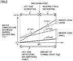
- Fig. 2 illustrates switching between hot-gas defrosting and reverse cycle defrosting.
- the refrigeration cycle apparatus according to the present embodiment is controlled to switch between different defrosting modes at the point where the amount of formed frost is Mfl.
- the water temperature decrease during the defrosting operation when the indoor load is large is ⁇ Twr1 in the case of reverse cycle defrosting, and ⁇ Twh1 in the case of hot-gas defrosting.
- a smaller water temperature decrease gives less discomfort to users.
- controller 100 selects the hot-gas defrosting mode.
- controller 100 selects the reverse cycle defrosting.
- a defrosting mode is selected based on the amount of formed frost for performing the defrosting operation at regular intervals, which is a technique corresponding to the technique disclosed in WO2015/162696 (PTL 1).
- the hot-gas defrosting mode In the hot-gas defrosting mode, almost no refrigerant gas is passed through water heat exchanger 20, which produces an advantage that cooling by refrigerant gas in water heat exchanger 20 does not occur during defrosting.
- the reverse cycle defrosting mode exhibits a higher defrosting effect and therefore, defrosting is completed in a shorter time.
- the indoor load is large, a longer time taken for defrosting is disadvantageous to the hot-gas defrosting method, because the temperature of water circulating through water heat exchanger 20 may decrease greater than the reverse cycle defrosting.
- the amount of formed frost Mfl is located at the position on the horizontal axis where the water temperature decrease represented by the vertical axis in Fig. 2 is the same for the two defrosting modes.
- Change of the indoor load causes change of the position of the amount of formed frost Mfl representing the switching point.
- the indoor load is lower than a certain value, the water temperature decrease during the defrosting operation is ⁇ Twr2 in the case of the reverse cycle defrosting, and ⁇ Twh2 in the case of the hot-gas defrosting. In this case, there is no intersection of the two graphs, and ⁇ Twr2 > ⁇ Twh2 always holds. Then, the hot-gas defrosting mode is selected for the defrosting operation.
- the defrosting mode is switched to the reverse cycle defrosting at the position of the amount of formed frost Mfl similar to that for the larger indoor load as described above, the water temperature decrease is larger than ⁇ Twh2 of the hot-gas defrosting, which may give discomfort to users.
- the water temperature decrease during defrosting in a chiller depends on the indoor load, and therefore, an optimum defrosting mode cannot be determined from only the amount of formed frost.
- the defrosting mode is switched from the hot-gas defrosting to the reverse cycle defrosting as the amount of formed frost increases in the case of a large indoor load, because this can suppress the water temperature decrease, while the hot-gas defrosting causes a smaller water temperature decrease than the reverse cycle defrosting even when the amount of formed frost increases in the case of a small indoor load.
- the water temperature decreases are calculated, depending on the amount of formed frost and the indoor load, supposing that the defrosting operation is performed in one of two defrosting modes, and a defrosting mode giving a smaller water temperature decrease is selected to perform the defrosting operation.
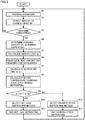
- Fig. 3 is a flowchart for illustrating control performed by the controller in Embodiment 1.
- the process of this flowchart is started in response to a heating operation start command from a user or a timer device, for example, and the heating operation is performed first in step S1. Subsequently, in step S2, amount of formed frost Mf of outdoor heat exchanger 40 is detected.
- Amount of formed frost Mf may be detected in any manner. For example, it can be detected by a frost amount sensor.
- the frost amount sensor applies light between fins of outdoor heat exchanger 40, and determines that frost is formed when the light is weakened (blocked). More than one monitoring site may be specified to estimate the area where frost is formed, relative to the total area.
- the relation between the rotational speed of a fan disposed in outdoor heat exchanger 40 and the quantity of air supplied by the fan may also be used. With formation of frost, the air resistance increases. Therefore, in order to produce the same quantity of air, the fan is rotated at a higher rotational speed.
- controller 100 determines in step S3 whether to perform the defrosting operation or not. For example, it may determine to perform the defrosting operation when the amount of formed frost Mf exceeds a predetermined decision value. Alternatively, it may determine to perform the defrosting operation when a predetermined time has elapsed since completion of the preceding defrosting operation. When it is determined in step S3 that the defrosting operation is not to be performed (NO in S3), the process is performed again from step S1.
- step S3 When it is determined in step S3 that the defrosting operation is to be performed (YES in S3), cooling amount qih, qir during defrosting is determined in step S4, and indoor load qj is calculated in step S5.
- Fig. 4 illustrates the cooling amount and the indoor load.
- the diagram shown in Fig. 4 is depicted by extracting a refrigerant circulation path and a water circulation path from Fig. 1 .
- Cooling amount qi [kW] during defrosting represents the amount of heat for cooling water in water heat exchanger during the defrosting operation
- qih represents the cooling amount during the hot-gas defrosting
- qir represents the cooling amount during the reverse cycle defrosting.
- Controller 100 calculates indoor load qj in accordance with the following formula (1).
- qj Q 1 ⁇ T 1 ⁇ T 2 ⁇ Cpw
- qj [kW] represents the indoor load
- Q1 [kg/s] represents the flow rate of a liquid medium
- T1 [°C] represents the inlet temperature at the inlet of indoor heat exchanger 220
- T2 [°C] represents the outlet temperature at the outlet of indoor heat exchanger 220
- Cpw [kJ/kg°C] represents the specific heat of water.
- controller 100 calculates heat amount Qfd [kJ/kg] required for defrosting, in accordance with the following formula (2).
- Qfd Mf ⁇ C
- Mf represents the amount of formed frost [kg] detected in step S2
- controller 100 calculates defrosting time th, tr in accordance with the following formula (3), where th represents the defrosting time required for hot-gas defrosting, and tr represents the defrosting time required for reverse cycle defrosting.
- t Qfd / qf
- Qfd represents the heat amount [kJ/kg] required for defrosting that is determined in accordance with formula (2)
- qf represents the amount of heat applied for defrosting that is a design value.
- qfh ⁇ qfr holds, where qfh represents the amount of heat applied for hot-gas defrosting, and qfr represents the amount of heat applied for reverse cycle defrosting, and qfh/qfr is approximately 1/3.
- controller 100 calculates water temperature decrease ⁇ Twh, ⁇ Twr during defrosting, in accordance with the following formula (4), where ⁇ Twh represents the water temperature decrease during hot-gas defrosting, and ⁇ Twr represents the water temperature decrease during reverse cycle defrosting.
- ⁇ ⁇ Tw k ⁇ qj + qi ⁇ t / M
- qj represents the indoor load [kW] calculated in step S5
- qi represents the cooling amount [kW] during defrosting determined in step S4
- t represents the defrosting time [s] calculated in step S7
- M represents the total amount of water circulated by liquid pump WP (system-used water amount, i.e., the amount of water used in the system)
- k represents a coefficient.
- System-used water amount M is a fixed value in Embodiment 1.
- step S9 controller 100 compares water temperature decrease ⁇ Twh during hot-gas defrosting with water temperature decrease ⁇ Twr during reverse cycle defrosting.
- step S10 controller 100 selects the hot-gas defrosting method to start defrosting.
- step S11 the hot-gas defrosting is ended after the operation for hot gas defrosting time th.
- step S9 when water temperature decrease ⁇ Twh during hot-gas defrosting is larger in step S9 (NO in S9), the process proceeds to step S12 in which controller 100 selects the reverse cycle defrosting method to start defrosting. Then, in step S13, the hot-gas defrosting is ended after the operation for hot-gas defrosting time tr.
- step S11 or S13 When one of the defrosting methods is completed in step S11 or S13, the process is performed again from step S 1.
- hot-gas defrosting and reverse cycle defrosting are different from each other in terms of amount of heat qf applied for defrosting and cooling amount qi during defrosting (qfh ⁇ qfr, qih ⁇ qir), and therefore, the water temperature decrease during defrosting varies depending on the defrosting method.
- water temperature decrease ⁇ T during each of the two defrosting operations is calculated from the operating state immediately before defrosting, and a defrosting method with smaller ⁇ T is selected. Thus, the water temperature decrease can be minimized.
- Embodiment 1 a defrosting mode is selected based on the indoor load.
- Embodiment 2 a description is given of control under which a defrosting mode is selected based further on system-used water amount M in addition to indoor load qj.
- System-used water amount M is the total amount of water circulated in a water pipe in a building, from a chiller through a liquid pump. After the building has been constructed and an air conditioning apparatus has been installed in the building, system-used water amount M is basically a fixed value that remains unchanged. However, for each building in which an air conditioning apparatus is installed, system-used water amount M may take a different value. It is therefore necessary, in Embodiment 1, to input system-used water amount M (fixed value) to controller 100 before the start of operation.
- System-used water amount M can be estimated based on the pressure difference between the inlet and the outlet of liquid pump WP.
- Fig. 5 is a schematic diagram showing a state where a chiller is installed.
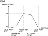
- Fig. 6 is a graph showing a pressure distribution in a water pipe.
- controller 100A calculates system-used water amount M in accordance with the following formula (5).
- M P 2 ⁇ P 1 / g ⁇ A
- a [m 2 ] represents the cross-sectional area of a passage in which the liquid medium circulates
- ⁇ [kg/m 3 ] represents the water density
- g [m/s 2 ] represents the acceleration of gravity.
- controller 100 may detect the pressure difference to calculate system-used water amount M, to thereby save the trouble of setting system-used water amount M in installing the air conditioning apparatus, which facilitates construction work.
- system-used water amount M may vary in use.
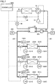
- Fig. 7 shows an example of an air conditioning system in which system-used water amount M varies in use.
- Fig. 7 regarding the portion in which refrigerant circulates (compressor 10, water heat exchanger 20, expansion valve 30, outdoor heat exchanger 40, pipes 90, 92, 94, 96, 97, 98, four-way valve 91, pipe 62, open/close valve 64), the configuration and the operation are similar to those in Fig. 1 , and therefore, the description thereof is not repeated herein.
- a refrigeration cycle apparatus shown in Fig. 7 includes indoor heat exchangers 220A to 220C connected in parallel to each other, instead of indoor heat exchanger 220 in the configuration in Fig. 1 .
- Indoor heat exchangers 220A to 220C are equipped with temperature sensors 231A to 231C, 232A to 232C, flow rate sensors 235A to 235C, and shutoff valves 264A to 264C, respectively.
- Indoor heat exchanger 220A is connected to water pipe 221 by water pipe 221A.
- Indoor heat exchanger 220A is connected to water pipe 222 by water pipe 222A.
- Shutoff valve 264A, temperature sensor 231A, and flow rate sensor 235A are disposed on water pipe 222A.
- Temperature sensor 232A is disposed on water pipe 221A.
- Indoor heat exchanger 220B is connected to water pipe 221 by water pipe 221B.
- Indoor heat exchanger 220B is connected to water pipe 222 by water pipe 222B.
- Shutoff valve 264B, temperature sensor 231B, and flow rate sensor 235B are disposed on water pipe 222B.
- Temperature sensor 232B is disposed on water pipe 221B.
- Indoor heat exchanger 220C is connected to water pipe 221 by water pipe 221C.
- Indoor heat exchanger 220C is connected to water pipe 222 by water pipe 222C.
- Shutoff valve 264C, temperature sensor 231C, and flow rate sensor 235C are disposed on water pipe 222C.
- Temperature sensor 232C is disposed on water pipe 221C.
- Pressure sensor 233 is disposed on water pipe 221 before branching into water pipes 221A to 221C, and pressure sensor 234 is disposed on water pipe 222 after the confluence of water pipes 222A to 222C.
- controller 100A opens or closes respective shutoff valves 264A to 264C.
- controller 100A opens the shutoff valve associated with the indoor heat exchanger to be used.
- controller 100A closes the shutoff valve associated with the indoor heat exchanger which is not to be used.
- shutoff valve 264A As shutoff valve 264A is closed, water does not circulate in water pipes 221A, 222A, and indoor heat exchanger 220A, and therefore, the amount of water circulating in water pipes 221, 222, namely the system-used water amount is decreased accordingly.
- shutoff valve 264B As shutoff valve 264B is closed, water does not circulate in water pipes 221B, 222B, and indoor heat exchanger 220B, and therefore, the system-used water amount is decreased accordingly.
- shutoff valve 264C As shutoff valve 264C is closed, water does not circulate in water pipes 221C, 222C, and indoor heat exchanger 220C, and therefore, the system-used water amount is decreased accordingly.
- shutoff valves 264A to 264C are opened, the system-used water amount is the maximum amount.
- the system-used water amount is the minimum amount.
- the refrigeration cycle apparatus shown in Fig. 7 is implemented by adding two indoor heat exchangers in parallel to the refrigeration cycle apparatus shown in Fig. 2 .
- the refrigeration cycle apparatus shown in Fig. 7 further includes indoor heat exchangers 220B, 220C which are configured to exchange heat between a liquid medium and indoor air and in which the liquid medium from liquid pump WP is circulated in parallel with indoor heat exchanger 220A, and further includes shutoff valves 264B, 264C for stopping flow of the liquid medium to second heat exchangers 220B, 220C.
- Fig. 7 shows three indoor heat exchangers connected in parallel to each other, the configuration is not limited to this and the number of parallel-connected indoor heat exchangers may be two or more than three.
- controller 100A selects one of the reverse cycle defrosting mode and the hot-gas defrosting mode for the defrosting operation to be performed.
- controller 100A controls four-way valve 91 so that refrigerant flows in the same direction as that during the cooling operation, and closes open/close valve 64.
- controller 100A controls four-way valve 91 so that refrigerant flows in the same direction as that during the heating operation, and opens open/close valve 64.
- Fig. 8 shows how the water temperature decrease during defrosting varies depending on the system-used water amount and the indoor load.
- Fig. 2 shows that a greater indoor load is accompanied by a greater water temperature decrease during the defrosting operation.
- Fig. 8 additionally shows that the water temperature tends to be less decreased even during the defrosting operation when the system-used water amount is large. Supposing that the indoor load consumes a certain amount of heat, then a larger amount of water used for heating means that the total amount of heat having been absorbed by water is large, which has a less influence on the water temperature.
- the defrosting mode is switched based on the amount of formed frost.
- hot-gas defrosting is used
- reverse cycle defrosting is used when the detected amount of formed frost is larger than the amount of formed frost at the intersection.
- the water temperature decrease during hot-gas defrosting is represented as ⁇ TwhB and the water temperature decrease during reverse cycle defrosting is represented as ⁇ TwrB.
- the line representing ⁇ TwhB and the line representing ⁇ TwrB cross each other at an intersection. Therefore, in order to reduce the water temperature decrease, the defrosting mode is switched based on the amount of formed frost. It should be noted that the intersection of the line for ⁇ TwhB and the line for ⁇ TwrB is shifted in the direction that the amount of formed frost increases, relative to the intersection of the line for ⁇ TwhA and the line for ⁇ TwrA.
- the water temperature decrease during hot-gas defrosting is represented as ⁇ TwhC and the water temperature decrease during reverse cycle defrosting is represented as ⁇ TwrC.
- the line representing ⁇ TwhC and the line representing ⁇ TwrC do not cross each other. Therefore, the defrosting mode is not switched and the hot-gas defrosting mode is selected.
- the water temperature decrease during hot-gas defrosting is represented as ⁇ TwhD and the water temperature decrease during reverse cycle defrosting is represented as ⁇ TwrD.
- the line representing ⁇ TwhD and the line representing ⁇ TwrD do not cross each other. Therefore, the defrosting mode is not switched and the hot-gas defrosting mode is selected.
- Fig. 9 is a flowchart for illustrating control performed by a controller in Embodiment 2.
- the flowchart in Fig. 9 corresponds to the flowchart described above with reference to Fig. 3 including additional step S20 of calculating used water amount M inserted between step S5 and step S6.
- the other steps are similar to those shown in Fig. 3 , and the description thereof is not repeated.
- step S20 controller 100A calculates system-used water amount M.
- system-used water amount M is a fixed value applied in advance as a design value.
- system-used water amount M is calculated in step S20 and used for calculating the water temperature decrease in step S8.
- controller 100A selects a defrosting mode based on the indoor load and the system-used water amount in step S9. Controller 100A calculates the system-used water amount in accordance with the above-indicated formula (5). While system-used water amount M may be calculated based on design information and the operating state of the shutoff valve, use of formula (5) eliminates the need to input design information such as the length of the water pipe, for example, and is therefore more preferred. Calculation of system-used water amount M based on the pressure difference between the inlet and the outlet of the liquid pump also eliminates the need to monitor the operating state of the shutoff valve, for example.
Landscapes
- Engineering & Computer Science (AREA)
- Physics & Mathematics (AREA)
- Mechanical Engineering (AREA)
- Thermal Sciences (AREA)
- General Engineering & Computer Science (AREA)
- Air Conditioning Control Device (AREA)
Abstract
Description
- The present invention relates to a refrigeration cycle apparatus, and particularly relates to a refrigeration cycle apparatus configured to perform a defrosting operation.
- A refrigeration cycle apparatus is known to require a defrosting operation in some cases. For example, in an air conditioner, frost may form on an outdoor heat exchanger during a heating operation to block an air passage between fins, and therefore, the frosted state is checked regularly to perform a defrosting operation as required.
-
WO2015/162696 (PTL 1) discloses a refrigerant circuit capable of both hot-gas defrosting and reverse cycle defrosting, for which the defrosting method is switched depending on the amount of formed frost. - PTL 1:
WO2015/162696 - According to studies by the inventors of the present application, a decrease of the water temperature during defrosting in a chiller (including a water heat exchanger and using water as a liquid medium to perform indoor air conditioning) depends on the indoor load and/or the amount of water used in the system, and it has therefore been found that an optimum defrosting method cannot be determined from only the amount of formed frost. If an optimum defrosting method cannot be determined, a decrease of the temperature of water circulating through an indoor heat exchanger during heating is greater than that when an optimum defrosting method is used, which may make users uncomfortable.
- An object of the present invention is to provide a refrigeration cycle apparatus capable of performing defrosting with a minimum decrease of the chiller water temperature.
- A refrigeration cycle apparatus of the present disclosure includes a water heat exchanger, a refrigeration cycle circuit, and a liquid medium circulation circuit. The water heat exchanger causes heat to be exchanged between refrigerant and a liquid medium. The refrigeration cycle circuit connects a compressor, the water heat exchanger, an expansion valve, and an outdoor heat exchanger successively, and connects a discharge side of the compressor to a part of the refrigeration cycle circuit between the expansion valve and the outdoor heat exchanger. The liquid medium circulation circuit connects the water heat exchanger, a pump, and an indoor heat exchanger.
- The refrigeration cycle circuit includes: a four-way valve configured to switch to connect the compressor to the water heat exchanger or to connect the compressor to the outdoor heat exchanger; a pipe connecting the discharge side of the compressor to the part of the refrigeration cycle circuit between the expansion valve and the outdoor heat exchanger; and a valve configured to block flow of the refrigerant in the pipe. The refrigeration cycle apparatus performs, based on an indoor load, a defrosting operation that is either one of a first defrosting operation of opening the valve, connecting the compressor to the water heat exchanger, and allowing refrigerant discharged from the compressor to flow to the outdoor heat exchanger, and a second defrosting operation of closing the valve, connecting the compressor to the outdoor heat exchanger, and allowing refrigerant discharged from the compressor to flow to the outdoor heat exchanger.
- The present invention selects a defrosting mode in which defrosting can be performed with a minimum decrease of the chiller water temperature.
-
-
Fig. 1 is an overall configuration diagram of a refrigeration cycle apparatus according toEmbodiment 1. -
Fig. 2 illustrates switching between hot-gas defrosting and reverse cycle defrosting. -
Fig. 3 is a flowchart for illustrating control performed by a controller inEmbodiment 1. -
Fig. 4 illustrates the cooling amount and the indoor load. -
Fig. 5 is a schematic diagram showing a state where a chiller is installed. -
Fig. 6 is a graph showing a pressure distribution in a water pipe. -
Fig. 7 shows an example of an air conditioning system in which the system-used water amount varies in use. -
Fig. 8 shows how the water temperature decrease during defrosting varies depending on the system-used water amount and the indoor load. -
Fig. 9 is a flowchart for illustrating control performed by a controller inEmbodiment 2. - Embodiments of the present invention are described in detail hereinafter with reference to the drawings. In the following, a plurality of embodiments are described. It is intended originally at the time of filing of the application that features described in connection with the embodiments may be combined as appropriate. In the drawings, the same or corresponding components are denoted by the same reference characters.
-
Fig. 1 is an overall configuration diagram of a refrigeration cycle apparatus according toEmbodiment 1. Referring toFig. 1 , the refrigeration cycle apparatus includes anoutdoor unit 1 and anindoor unit 201.Outdoor unit 1 includes acompressor 10, awater heat exchanger 20, anexpansion valve 30, anoutdoor heat exchanger 40,pipes way valve 91, an open/close valve 64, and acontroller 100.Outdoor unit 1 further includes a refrigeration cyclecircuit connecting compressor 10,water heat exchanger 20,expansion valve 30, andoutdoor heat exchanger 40 successively bypipes pipe 62, a discharge side ofcompressor 10 to a part of the refrigeration cycle circuit betweenexpansion valve 30 andoutdoor heat exchanger 40. - Pipe 90 connects four-
way valve 91 towater heat exchanger 20. Pipe 92 connectswater heat exchanger 20 toexpansion valve 30. Pipe 94 connectsexpansion valve 30 tooutdoor heat exchanger 40. Pipe 96 connectsoutdoor heat exchanger 40 to four-way valve 91. A discharge outlet ofcompressor 10 is connected bypipe 98 to the four-way valve, and a suction inlet ofcompressor 10 is connected bypipe 97 to four-way valve 91. - A refrigerant passage connecting
water heat exchanger 20 tooutdoor heat exchanger 40 includespipe 92 andpipe 94.Expansion valve 30 is disposed at the boundary betweenpipe 92 andpipe 94. -
Outdoor heat exchanger 40 is configured to exchange heat between refrigerant and outdoor air.Water heat exchanger 20 is configured to exchange heat between water and refrigerant. -
Compressor 10 is configured to have its operating frequency variable in accordance with a control signal received fromcontroller 100. The operating frequency ofcompressor 10 is changed to adjust the output ofcompressor 10. - For a heating operation, four-
way valve 91 connects the discharge outlet ofcompressor 10 to pipe 90 so as to cause refrigerant to flow in the order fromcompressor 10 towater heat exchanger 20 in the direction indicated by solid-line arrows, and also connects the suction inlet ofcompressor 10 topipe 96. For a cooling operation or reverse cycle defrosting operation, four-way valve 91 connects the discharge outlet ofcompressor 10 topipe 96 so as to cause refrigerant to flow in the order fromcompressor 10 tooutdoor heat exchanger 40 in the direction indicated by broken-line arrows, and also connects the suction inlet ofcompressor 10 to pipe 90. - In other words, four-
way valve 91 is configured to switch the refrigerant flow direction between a first direction (heating) and a second direction (cooling, reverse cycle defrosting). The first direction (heating) is a flow direction for feeding refrigerant discharged fromcompressor 10 towater heat exchanger 20 and returning refrigerant fromoutdoor heat exchanger 40 back tocompressor 10. The second direction (cooling, reverse cycle defrosting) is a flow direction for feeding refrigerant discharged fromcompressor 10 tooutdoor heat exchanger 40 and returning refrigerant fromwater heat exchanger 20 back tocompressor 10. - Pipe 62 connects a branching
portion 60 located onpipe 98 which is a discharge side pipe ofcompressor 10, to aconfluence portion 66 located onpipe 94. Pipe 62 is a flow passage bypassingwater heat exchanger 20 andexpansion valve 30. Open/close valve 64 is disposed inpipe 62 and configured to have its degree of opening adjusted in accordance with a control signal received fromcontroller 100 for adjusting the amount of refrigerant flowing throughpipe 62. Open/close valve 64 may be a simple valve for performing opening/closing operation only. - The refrigeration cycle apparatus in
Fig. 1 hasindoor unit 201 including a liquid medium circulation circuit. The liquid medium circulation circuit includes anindoor heat exchanger 220, a liquid pump WP, andwater pipes 221 to 223 serving as pipes for circulating water in the order ofwater heat exchanger 20, liquid pump WP, andindoor heat exchanger 220, and also includestemperature sensors 231, 232, apressure sensor 234, and aflow rate sensor 235. The liquid medium circulation circuit connectswater heat exchanger 20, liquid pump WP, andindoor heat exchanger 220 to each other. -
Water pipe 221 connects liquid pump WP toindoor heat exchanger 220,water pipe 222 connectsindoor water pipe 222 towater heat exchanger 20, andwater pipe 223 connectswater heat exchanger 20 toindoor heat exchanger 220. Temperature sensor 231 is a sensor disposed at the outlet ofindoor heat exchanger 220 for detecting the temperature of water flowing out fromindoor heat exchanger 220, andtemperature sensor 232 is a sensor disposed at the inlet ofindoor heat exchanger 220 for detecting the temperature of water flowing intoindoor heat exchanger 220. -
Pressure sensor 234 is a sensor disposed at the outlet ofindoor heat exchanger 220 for detecting the pressure of water flowing out fromindoor heat exchanger 220, and flowrate sensor 235 is a sensor disposed at the outlet ofindoor heat exchanger 220 for detecting the flow rate of water.Indoor heat exchanger 220 is configured to exchange heat between indoor air and water circulating throughwater pipes 221 to 223. -
Pressure sensor 234 detects pressure P2 of water at the outlet ofindoor heat exchanger 220, and outputs the detected value tocontroller 100. Temperature sensor 231 detects water temperature T1 at the outlet ofindoor heat exchanger 220, and outputs the detected value tocontroller 100.Temperature sensor 232 detects water temperature T2 at the inlet ofindoor heat exchanger 220, and outputs the detected value tocontroller 100.Flow rate sensor 235 is disposed at the outlet ofindoor heat exchanger 220, detects flow rate Q1 of water, and outputs the detected value tocontroller 100. -
Controller 100 includes a CPU (Central Processing Unit), a storage device, and an input/output buffer, for example (they are not shown), for controlling each device in the refrigeration cycle apparatus. This control is not limited to processing by software but may be processing by a dedicated hardware (electronic circuit). - First, a basic operation of heating is described. During the heating operation, refrigerant flows in
outdoor unit 1 as indicated by the solid-line arrows and the solid-line flow path in four-way valve 91. Refrigerant flowing inpipe 96 is sucked through four-way valve 91 intocompressor 10, andcompressor 10 compresses the sucked refrigerant to discharge the compressed refrigerant topipe 90 through four-way valve 91. - The refrigerant discharged from
compressor 10 is overheated vapor of high temperature and high pressure. Inwater heat exchanger 20, the refrigerant exchanges heat with water which is a liquid medium flowing inindoor unit 201, and the refrigerant is then condensed into liquid form. At this time, the temperature of water flowing inindoor unit 201 is increased by the heat discharged from the refrigerant. - After this, the refrigerant liquefied in
water heat exchanger 20 is lowered in pressure byexpansion valve 30.Expansion valve 30 is configured to have its degree of opening adjustable in accordance with a control signal received fromcontroller 100. As the degree of opening ofexpansion valve 30 is changed in the close direction, the refrigerant pressure at the outlet ofexpansion valve 30 decreases and the refrigerant dryness increases. In contrast, as the degree of opening ofexpansion valve 30 is changed in the open direction, the refrigerant pressure at the outlet ofexpansion valve 30 increases and the refrigerant dryness decreases. - The refrigerant lowered in pressure by
expansion valve 30 flows intooutdoor heat exchanger 40 to exchange heat with outdoor air inoutdoor heat exchanger 40. The refrigerant is then evaporated into overheated vapor that flows throughpipe 97 into the compressor. - The water (hot water) having the temperature increased through
water heat exchanger 20 inindoor unit 201 is delivered toindoor heat exchanger 220 by liquid pump WP. The hot water delivered by liquid pump WP exchanges heat, inindoor heat exchanger 220, with indoor air. The heat discharged from the hot water into the outside air is used to heat the inside of a room. - Moreover, in order to melt frost formed on
outdoor heat exchanger 40 during the heating operation, a defrosting operation may be selected from a hot-gas defrosting operation and a reverse cycle defrosting operation. The hot-gas defrosting operation is an operation for melting frost formed onoutdoor heat exchanger 40 by feeding, directly tooutdoor heat exchanger 40, the overheated vapor of high temperature and high pressure discharged fromcompressor 10, with a similar setting of four-way valve 91 to that during the heating operation. The reverse cycle defrosting operation is described later herein. - The setting for four-
way valve 91 during the hot-gas defrosting operation is also similar to that during the heating operation. During the hot-gas defrosting operation, the direction in which refrigerant flows is basically similar to that during the heating operation. However, the flow passage resistance in the flow passage throughwater heat exchanger 20 andexpansion valve 30 is larger than the flow passage resistance inpipe 62. Therefore, as open/close valve 64 is opened, most of the refrigerant discharged fromcompressor 10 flows topipe 62 as indicated by the arrow of an alternate long and short dashed line, and the refrigerant does not flow topipe 90. - Next, a cooling operation is described. During the cooling operation, four-
way valve 91 forms a passage indicated by broken lines inoutdoor unit 1, and refrigerant flows in the direction indicated by the broken-line arrows. Specifically, refrigerant discharged fromcompressor 10 flows throughoutdoor heat exchanger 40,expansion valve 30, andwater heat exchanger 20 in this order. As a result,water heat exchanger 20 acts as an evaporator andoutdoor heat exchanger 40 acts as a condenser. Accordingly, heat is absorbed from water inwater heat exchanger 20, and discharged from the outdoor unit to outdoor air. - A reverse cycle defrosting operation may be selected as a defrosting operation in order to melt frost formed on
outdoor heat exchanger 40 during the heating operation. The reverse cycle defrosting operation is an operation for melting frost formed onoutdoor heat exchanger 40 by feeding, tooutdoor heat exchanger 40, overheated vapor of high temperature and high pressure discharged fromcompressor 10, with the same setting of four-way valve 91 as that during the cooling operation. During the reverse cycle defrosting operation, the setting of four-way valve 91 and the direction in which refrigerant flows are similar to those during the cooling operation, and open/close valve 64 is closed. -
Controller 100 controls switching of four-way valve 91 based on whether the apparatus is set in the cooling mode or the heating mode, controls operation ofcompressor 10 in response to an operational instruction forcompressor 10, and controls stoppage ofcompressor 10 in response to an instruction to stopcompressor 10. Moreover,controller 100 controls the operating frequency ofcompressor 10, the degree of opening ofexpansion valve 30, and the rotational speed of an indoor fan and an outdoor fan (not shown), so that the refrigeration cycle apparatus exhibits a desired performance. -
Controller 100 also selects one of a reverse cycle defrosting mode and a hot-gas defrosting mode as a defrosting mode for performing the defrosting operation, depending on the magnitude of the indoor load. In the reverse cycle defrosting mode,controller 100 controls four-way valve 91 so that refrigerant flows in the second direction which is the same as that in the cooling operation, and closes open/close valve 64. In contrast, in the hot-gas defrosting mode,controller 100 controls four-way valve 91 so that refrigerant flows in the first direction which is the same as that in the heating operation, and opens open/close valve 64. -
Fig. 2 illustrates switching between hot-gas defrosting and reverse cycle defrosting. As shown inFig. 2 , when the indoor load is large, the refrigeration cycle apparatus according to the present embodiment is controlled to switch between different defrosting modes at the point where the amount of formed frost is Mfl. - The water temperature decrease during the defrosting operation when the indoor load is large is ΔTwr1 in the case of reverse cycle defrosting, and ΔTwh1 in the case of hot-gas defrosting. A smaller water temperature decrease gives less discomfort to users. Then, where a relation: the amount of formed frost < Mfl is satisfied, ΔTwr1 > ΔTwh1 holds, and therefore,
controller 100 selects the hot-gas defrosting mode. Where a relation: the amount of formed frost >Mfl is satisfied, ΔTwr1 < ΔThr1 holds, and therefore,controller 100 selects the reverse cycle defrosting. - Supposing that the position of the amount of formed frost Mfl representing this switching point is unchanged, a defrosting mode is selected based on the amount of formed frost for performing the defrosting operation at regular intervals, which is a technique corresponding to the technique disclosed in
WO2015/162696 (PTL 1). - In the hot-gas defrosting mode, almost no refrigerant gas is passed through
water heat exchanger 20, which produces an advantage that cooling by refrigerant gas inwater heat exchanger 20 does not occur during defrosting. In contrast, the reverse cycle defrosting mode exhibits a higher defrosting effect and therefore, defrosting is completed in a shorter time. When the indoor load is large, a longer time taken for defrosting is disadvantageous to the hot-gas defrosting method, because the temperature of water circulating throughwater heat exchanger 20 may decrease greater than the reverse cycle defrosting. For these reasons, the amount of formed frost Mfl is located at the position on the horizontal axis where the water temperature decrease represented by the vertical axis inFig. 2 is the same for the two defrosting modes. - Change of the indoor load, however, causes change of the position of the amount of formed frost Mfl representing the switching point. When the indoor load is lower than a certain value, the water temperature decrease during the defrosting operation is ΔTwr2 in the case of the reverse cycle defrosting, and ΔTwh2 in the case of the hot-gas defrosting. In this case, there is no intersection of the two graphs, and ΔTwr2 > ΔTwh2 always holds. Then, the hot-gas defrosting mode is selected for the defrosting operation. When the indoor load is small and the defrosting mode is switched to the reverse cycle defrosting at the position of the amount of formed frost Mfl similar to that for the larger indoor load as described above, the water temperature decrease is larger than ΔTwh2 of the hot-gas defrosting, which may give discomfort to users.
- In consideration of the foregoing, the water temperature decrease during defrosting in a chiller (including a water heat exchanger and using water for indoor air conditioning) depends on the indoor load, and therefore, an optimum defrosting mode cannot be determined from only the amount of formed frost. Specifically, according to the results of studies (results of calculations) by the inventors, it has been found that, in order to minimize the water temperature decrease in the chiller, the defrosting mode is switched from the hot-gas defrosting to the reverse cycle defrosting as the amount of formed frost increases in the case of a large indoor load, because this can suppress the water temperature decrease, while the hot-gas defrosting causes a smaller water temperature decrease than the reverse cycle defrosting even when the amount of formed frost increases in the case of a small indoor load.
- In the present embodiment, therefore, when the defrosting operation is to be started, the water temperature decreases are calculated, depending on the amount of formed frost and the indoor load, supposing that the defrosting operation is performed in one of two defrosting modes, and a defrosting mode giving a smaller water temperature decrease is selected to perform the defrosting operation.
-
Fig. 3 is a flowchart for illustrating control performed by the controller inEmbodiment 1. Referring toFig. 3 , the process of this flowchart is started in response to a heating operation start command from a user or a timer device, for example, and the heating operation is performed first in step S1. Subsequently, in step S2, amount of formed frost Mf ofoutdoor heat exchanger 40 is detected. - Amount of formed frost Mf may be detected in any manner. For example, it can be detected by a frost amount sensor. The frost amount sensor applies light between fins of
outdoor heat exchanger 40, and determines that frost is formed when the light is weakened (blocked). More than one monitoring site may be specified to estimate the area where frost is formed, relative to the total area. The relation between the rotational speed of a fan disposed inoutdoor heat exchanger 40 and the quantity of air supplied by the fan may also be used. With formation of frost, the air resistance increases. Therefore, in order to produce the same quantity of air, the fan is rotated at a higher rotational speed. - Subsequently,
controller 100 determines in step S3 whether to perform the defrosting operation or not. For example, it may determine to perform the defrosting operation when the amount of formed frost Mf exceeds a predetermined decision value. Alternatively, it may determine to perform the defrosting operation when a predetermined time has elapsed since completion of the preceding defrosting operation. When it is determined in step S3 that the defrosting operation is not to be performed (NO in S3), the process is performed again from step S1. - When it is determined in step S3 that the defrosting operation is to be performed (YES in S3), cooling amount qih, qir during defrosting is determined in step S4, and indoor load qj is calculated in step S5.
-
Fig. 4 illustrates the cooling amount and the indoor load. The diagram shown inFig. 4 is depicted by extracting a refrigerant circulation path and a water circulation path fromFig. 1 . Cooling amount qi [kW] during defrosting represents the amount of heat for cooling water in water heat exchanger during the defrosting operation, qih represents the cooling amount during the hot-gas defrosting, and qir represents the cooling amount during the reverse cycle defrosting. -
Controller 100 calculates indoor load qj in accordance with the following formula (1).
- In the above formula, qj [kW] represents the indoor load, Q1 [kg/s] represents the flow rate of a liquid medium, T1 [°C] represents the inlet temperature at the inlet of
indoor heat exchanger 220, T2 [°C] represents the outlet temperature at the outlet ofindoor heat exchanger 220, and Cpw [kJ/kg°C] represents the specific heat of water. - Subsequently, in step S6,
controller 100 calculates heat amount Qfd [kJ/kg] required for defrosting, in accordance with the following formula (2).
- In the above formula, Mf represents the amount of formed frost [kg] detected in step S2, and C represents the latent heat of fusion of ice (constant = 334 [kJ/kg]).
- Subsequently, in step S7,
controller 100 calculates defrosting time th, tr in accordance with the following formula (3), where th represents the defrosting time required for hot-gas defrosting, and tr represents the defrosting time required for reverse cycle defrosting.
- In formula (3), Qfd represents the heat amount [kJ/kg] required for defrosting that is determined in accordance with formula (2), and qf represents the amount of heat applied for defrosting that is a design value. Here, qfh <qfr holds, where qfh represents the amount of heat applied for hot-gas defrosting, and qfr represents the amount of heat applied for reverse cycle defrosting, and qfh/qfr is approximately 1/3.
- Subsequently, in step S8,
controller 100 calculates water temperature decrease ΔTwh, ΔTwr during defrosting, in accordance with the following formula (4), where ΔTwh represents the water temperature decrease during hot-gas defrosting, and ΔTwr represents the water temperature decrease during reverse cycle defrosting.
- In Formula (4), qj represents the indoor load [kW] calculated in step S5, qi represents the cooling amount [kW] during defrosting determined in step S4, t represents the defrosting time [s] calculated in step S7, M represents the total amount of water circulated by liquid pump WP (system-used water amount, i.e., the amount of water used in the system), and k represents a coefficient. System-used water amount M is a fixed value in
Embodiment 1. - In step S9,
controller 100 compares water temperature decrease ΔTwh during hot-gas defrosting with water temperature decrease ΔTwr during reverse cycle defrosting. When water temperature decrease ΔTwh during hot-gas defrosting is smaller (YES in S9), the process proceeds to step S10 in whichcontroller 100 selects the hot-gas defrosting method to start defrosting. Then, in step S11, the hot-gas defrosting is ended after the operation for hot gas defrosting time th. - In contrast, when water temperature decrease ΔTwh during hot-gas defrosting is larger in step S9 (NO in S9), the process proceeds to step S12 in which
controller 100 selects the reverse cycle defrosting method to start defrosting. Then, in step S13, the hot-gas defrosting is ended after the operation for hot-gas defrosting time tr. - When one of the defrosting methods is completed in step S11 or S13, the process is performed again from
step S 1. - As seen from the foregoing, hot-gas defrosting and reverse cycle defrosting are different from each other in terms of amount of heat qf applied for defrosting and cooling amount qi during defrosting (qfh < qfr, qih < qir), and therefore, the water temperature decrease during defrosting varies depending on the defrosting method. In
Embodiment 1, water temperature decrease ΔT during each of the two defrosting operations is calculated from the operating state immediately before defrosting, and a defrosting method with smaller ΔT is selected. Thus, the water temperature decrease can be minimized. - In the above description of
Embodiment 1, a defrosting mode is selected based on the indoor load. In connection withEmbodiment 2, a description is given of control under which a defrosting mode is selected based further on system-used water amount M in addition to indoor load qj. - System-used water amount M is the total amount of water circulated in a water pipe in a building, from a chiller through a liquid pump. After the building has been constructed and an air conditioning apparatus has been installed in the building, system-used water amount M is basically a fixed value that remains unchanged. However, for each building in which an air conditioning apparatus is installed, system-used water amount M may take a different value. It is therefore necessary, in
Embodiment 1, to input system-used water amount M (fixed value) tocontroller 100 before the start of operation. - System-used water amount M can be estimated based on the pressure difference between the inlet and the outlet of liquid pump WP.
Fig. 5 is a schematic diagram showing a state where a chiller is installed.Fig. 6 is a graph showing a pressure distribution in a water pipe. As shown inFigs. 5 and6 , supposing that the liquid pressure at the outlet of the liquid pump is P1 [Mpa] and the pressure at the inlet of the indoor unit is P2 as shown inFigs. 5 and6 ,controller 100A calculates system-used water amount M in accordance with the following formula (5).
- In formula (5), A [m2] represents the cross-sectional area of a passage in which the liquid medium circulates, ρ [kg/m3] represents the water density, and g [m/s2] represents the acceleration of gravity.
- Thus,
controller 100 may detect the pressure difference to calculate system-used water amount M, to thereby save the trouble of setting system-used water amount M in installing the air conditioning apparatus, which facilitates construction work. - Moreover, system-used water amount M may vary in use.
Fig. 7 shows an example of an air conditioning system in which system-used water amount M varies in use. - In
Fig. 7 , regarding the portion in which refrigerant circulates (compressor 10,water heat exchanger 20,expansion valve 30,outdoor heat exchanger 40,pipes way valve 91,pipe 62, open/close valve 64), the configuration and the operation are similar to those inFig. 1 , and therefore, the description thereof is not repeated herein. - A refrigeration cycle apparatus shown in
Fig. 7 includesindoor heat exchangers 220A to 220C connected in parallel to each other, instead ofindoor heat exchanger 220 in the configuration inFig. 1 .Indoor heat exchangers 220A to 220C are equipped with temperature sensors 231A to 231C, 232A to 232C,flow rate sensors 235A to 235C, andshutoff valves 264A to 264C, respectively. -
Indoor heat exchanger 220A is connected towater pipe 221 bywater pipe 221A.Indoor heat exchanger 220A is connected towater pipe 222 bywater pipe 222A.Shutoff valve 264A, temperature sensor 231A, and flowrate sensor 235A are disposed onwater pipe 222A. Temperature sensor 232A is disposed onwater pipe 221A. -
Indoor heat exchanger 220B is connected towater pipe 221 bywater pipe 221B.Indoor heat exchanger 220B is connected towater pipe 222 bywater pipe 222B.Shutoff valve 264B,temperature sensor 231B, and flowrate sensor 235B are disposed onwater pipe 222B.Temperature sensor 232B is disposed onwater pipe 221B. -
Indoor heat exchanger 220C is connected towater pipe 221 bywater pipe 221C.Indoor heat exchanger 220C is connected towater pipe 222 bywater pipe 222C.Shutoff valve 264C, temperature sensor 231C, and flowrate sensor 235C are disposed onwater pipe 222C.Temperature sensor 232C is disposed onwater pipe 221C. -
Pressure sensor 233 is disposed onwater pipe 221 before branching intowater pipes 221A to 221C, andpressure sensor 234 is disposed onwater pipe 222 after the confluence ofwater pipes 222A to 222C. - In such a configuration, depending on whether
indoor heat exchangers 220A to 220C are used or not,controller 100A opens or closesrespective shutoff valves 264A to 264C. When an indoor heat exchanger is to be used,controller 100A opens the shutoff valve associated with the indoor heat exchanger to be used. When an indoor heat exchanger is not to be used,controller 100A closes the shutoff valve associated with the indoor heat exchanger which is not to be used. - As
shutoff valve 264A is closed, water does not circulate inwater pipes indoor heat exchanger 220A, and therefore, the amount of water circulating inwater pipes shutoff valve 264B is closed, water does not circulate inwater pipes indoor heat exchanger 220B, and therefore, the system-used water amount is decreased accordingly. Asshutoff valve 264C is closed, water does not circulate inwater pipes indoor heat exchanger 220C, and therefore, the system-used water amount is decreased accordingly. - Therefore, when all of
shutoff valves 264A to 264C are opened, the system-used water amount is the maximum amount. When any one of the shutoff valves is closed, for example, whenshutoff valve 264A is opened andshutoff valves - The refrigeration cycle apparatus shown in
Fig. 7 is implemented by adding two indoor heat exchangers in parallel to the refrigeration cycle apparatus shown inFig. 2 . Specifically, supposing thatindoor heat exchanger 220A corresponds toindoor heat exchanger 220 inFig. 2 , the refrigeration cycle apparatus shown inFig. 7 further includesindoor heat exchangers indoor heat exchanger 220A, and further includesshutoff valves second heat exchangers Fig. 7 shows three indoor heat exchangers connected in parallel to each other, the configuration is not limited to this and the number of parallel-connected indoor heat exchangers may be two or more than three. - Based on the magnitude of the indoor load and the system-used water amount,
controller 100A selects one of the reverse cycle defrosting mode and the hot-gas defrosting mode for the defrosting operation to be performed. In the reverse cycle defrosting mode,controller 100A controls four-way valve 91 so that refrigerant flows in the same direction as that during the cooling operation, and closes open/close valve 64. In the hot-gas defrosting mode,controller 100A controls four-way valve 91 so that refrigerant flows in the same direction as that during the heating operation, and opens open/close valve 64. -
Fig. 8 shows how the water temperature decrease during defrosting varies depending on the system-used water amount and the indoor load. -
Fig. 2 shows that a greater indoor load is accompanied by a greater water temperature decrease during the defrosting operation.Fig. 8 additionally shows that the water temperature tends to be less decreased even during the defrosting operation when the system-used water amount is large. Supposing that the indoor load consumes a certain amount of heat, then a larger amount of water used for heating means that the total amount of heat having been absorbed by water is large, which has a less influence on the water temperature. - Specifically, in
Fig. 8 , when the system-used water amount is small and the indoor load is large, the water temperature decrease during hot-gas defrosting is represented as ΔTwhA and the water temperature decrease during reverse cycle defrosting is represented as ΔTwrA. The line representing ΔTwhA and the line representing ΔTwrA cross each other at an intersection. Therefore, in order to reduce the water temperature decrease, the defrosting mode is switched based on the amount of formed frost. When a detected amount of formed frost is smaller than the amount of formed frost at the intersection, hot-gas defrosting is used, while reverse cycle defrosting is used when the detected amount of formed frost is larger than the amount of formed frost at the intersection. - When the system-used water amount is large and the indoor load is large, the water temperature decrease during hot-gas defrosting is represented as ΔTwhB and the water temperature decrease during reverse cycle defrosting is represented as ΔTwrB. The line representing ΔTwhB and the line representing ΔTwrB cross each other at an intersection. Therefore, in order to reduce the water temperature decrease, the defrosting mode is switched based on the amount of formed frost. It should be noted that the intersection of the line for ΔTwhB and the line for ΔTwrB is shifted in the direction that the amount of formed frost increases, relative to the intersection of the line for ΔTwhA and the line for ΔTwrA.
- In contrast, when the system-used water amount is small and the indoor load is small, the water temperature decrease during hot-gas defrosting is represented as ΔTwhC and the water temperature decrease during reverse cycle defrosting is represented as ΔTwrC. The line representing ΔTwhC and the line representing ΔTwrC do not cross each other. Therefore, the defrosting mode is not switched and the hot-gas defrosting mode is selected.
- Likewise, when the system-used water amount is large and the indoor load is small, the water temperature decrease during hot-gas defrosting is represented as ΔTwhD and the water temperature decrease during reverse cycle defrosting is represented as ΔTwrD. The line representing ΔTwhD and the line representing ΔTwrD do not cross each other. Therefore, the defrosting mode is not switched and the hot-gas defrosting mode is selected.
- As seen from the above, there is a tendency that the reverse cycle defrosting is likely to be selected when the indoor load is large, while the hot-gas defrosting is likely to be selected when the system-used water amount is large.
-
Fig. 9 is a flowchart for illustrating control performed by a controller inEmbodiment 2. The flowchart inFig. 9 corresponds to the flowchart described above with reference toFig. 3 including additional step S20 of calculating used water amount M inserted between step S5 and step S6. The other steps are similar to those shown inFig. 3 , and the description thereof is not repeated. - In step S20,
controller 100A calculates system-used water amount M. In the process inFig. 3 , system-used water amount M is a fixed value applied in advance as a design value. In contrast, in the process inFig. 9 , system-used water amount M is calculated in step S20 and used for calculating the water temperature decrease in step S8. - Accordingly,
controller 100A selects a defrosting mode based on the indoor load and the system-used water amount in step S9.Controller 100A calculates the system-used water amount in accordance with the above-indicated formula (5). While system-used water amount M may be calculated based on design information and the operating state of the shutoff valve, use of formula (5) eliminates the need to input design information such as the length of the water pipe, for example, and is therefore more preferred. Calculation of system-used water amount M based on the pressure difference between the inlet and the outlet of the liquid pump also eliminates the need to monitor the operating state of the shutoff valve, for example. - It should be construed that embodiments disclosed herein are given by way of illustration in all respects, not by way of limitation. It is intended that the scope of the present invention is defined by claims, not by the description above, and encompasses all modifications and variations equivalent in meaning and scope to the claims.
- 1 outdoor unit; 10 compressor; 20 water heat exchanger; 30 expansion valve; 40 outdoor heat exchanger; 60 branching portion; 64 open/close valve; 66 confluence portion; 62, 90, 92, 94, 96, 97, 98 pipe; 91 four-way valve; 100, 100A controller; 201 indoor unit; 231, 231A-231C, 232, 232A-232C temperature sensor; 220, 220A, 220B, 220C indoor heat exchanger; 221, 221A-221C, 222, 222A-222C, 223 water pipe; 233, 234 pressure sensor; 235, 235A-235C flow rate sensor; 264A-264C shutoff valve; WP liquid pump
Claims (7)
- A refrigeration cycle apparatus comprising:a water heat exchanger configured to cause heat to be exchanged between refrigerant and a liquid medium;a refrigeration cycle circuit connecting a compressor, the water heat exchanger, an expansion valve, and an outdoor heat exchanger successively and connecting a discharge side of the compressor to a part of the refrigeration cycle circuit between the expansion valve and the outdoor heat exchanger; anda liquid medium circulation circuit connecting the water heat exchanger, a pump, and an indoor heat exchanger,the refrigeration cycle circuit comprising:a four-way valve configured to switch to connect the compressor to the water heat exchanger or to connect the compressor to the outdoor heat exchanger;a pipe connecting the discharge side of the compressor to the part of the refrigeration cycle circuit between the expansion valve and the outdoor heat exchanger; anda valve configured to block flow of the refrigerant in the pipe, whereinthe refrigeration cycle apparatus performs, based on an indoor load, a defrosting operation that is either one ofa first defrosting operation of opening the valve, connecting the compressor to the water heat exchanger, and allowing refrigerant discharged from the compressor to flow to the outdoor heat exchanger, anda second defrosting operation of closing the valve, connecting the compressor to the outdoor heat exchanger, and allowing refrigerant discharged from the compressor to flow to the outdoor heat exchanger.
- The refrigeration cycle apparatus according to claim 1, further comprising:a first temperature sensor and a second temperature sensor configured to detect an outlet temperature of the liquid medium at an outlet of the indoor heat exchanger and an inlet temperature of the liquid medium at an inlet of the indoor heat exchanger, respectively; anda first flow rate sensor configured to detect a flow rate of the liquid medium, whereinthe defrosting operation is selected based on respective outputs of the first temperature sensor and the second temperature sensor and an output of the first flow rate sensor.
- The refrigeration cycle apparatus according to claim 1 or 2, wherein
the indoor load is calculated in accordance with a formula:
- The refrigeration cycle apparatus according claim 2, further comprising:a second indoor heat exchanger configured to cause heat to be exchanged between the liquid medium and indoor air, and allow the liquid medium from the pump to circulate through the second indoor heat exchanger in parallel with the indoor heat exchanger;a third temperature sensor and a fourth temperature sensor configured to detect an outlet temperature of the liquid medium at an outlet of the second indoor heat exchanger and an inlet temperature of the liquid medium at an inlet of the second indoor heat exchanger, respectively; anda second flow rate sensor configured to detect a flow rate of the liquid medium flowing through the second indoor heat exchanger.
- The refrigeration cycle apparatus according to claim 1, wherein the defrosting operation is selected based on the indoor load and a system-used water amount.
- The refrigeration cycle apparatus according to claim 5, wherein the system-used water amount is calculated in accordance with a formula:

- The refrigeration cycle apparatus according to claim 5, further comprising:a second indoor heat exchanger configured to cause heat to be exchanged between the liquid medium and indoor air, and allow the liquid medium from the pump to circulate through the second indoor heat exchanger in parallel with the indoor heat exchanger; anda shutoff valve configured to stop flow of the liquid medium to the second indoor heat exchanger.
Applications Claiming Priority (1)
| Application Number | Priority Date | Filing Date | Title |
|---|---|---|---|
| PCT/JP2017/024958 WO2019008742A1 (en) | 2017-07-07 | 2017-07-07 | Refrigeration cycle device |
Publications (2)
| Publication Number | Publication Date |
|---|---|
| EP3650770A1 true EP3650770A1 (en) | 2020-05-13 |
| EP3650770A4 EP3650770A4 (en) | 2020-12-23 |
Family
ID=64949850
Family Applications (1)
| Application Number | Title | Priority Date | Filing Date |
|---|---|---|---|
| EP17917003.0A Withdrawn EP3650770A4 (en) | 2017-07-07 | 2017-07-07 | REFRIGERATION CIRCUIT DEVICE |
Country Status (4)
| Country | Link |
|---|---|
| US (1) | US11585578B2 (en) |
| EP (1) | EP3650770A4 (en) |
| JP (1) | JP6804648B2 (en) |
| WO (1) | WO2019008742A1 (en) |
Cited By (1)
| Publication number | Priority date | Publication date | Assignee | Title |
|---|---|---|---|---|
| EP4184080A4 (en) * | 2020-07-15 | 2023-09-13 | Mitsubishi Electric Corporation | OUTDOOR UNIT FOR A COOLING DEVICE AND COOLING DEVICE THEREFOR |
Families Citing this family (2)
| Publication number | Priority date | Publication date | Assignee | Title |
|---|---|---|---|---|
| CN110319631B (en) * | 2019-07-18 | 2020-09-01 | 珠海格力电器股份有限公司 | Defrosting control method and device, storage medium and heat pump unit |
| JP7610443B2 (en) * | 2021-03-24 | 2025-01-08 | サンデン株式会社 | Vehicle air conditioning system |
Family Cites Families (20)
| Publication number | Priority date | Publication date | Assignee | Title |
|---|---|---|---|---|
| JPS62134464A (en) * | 1985-12-06 | 1987-06-17 | 三菱電機株式会社 | Controller for air conditioner |
| JPH04270876A (en) * | 1991-02-27 | 1992-09-28 | Matsushita Electric Ind Co Ltd | Defrosting controller for heat pump type air-conditioning machine |
| JP3888403B2 (en) * | 1997-12-18 | 2007-03-07 | 株式会社富士通ゼネラル | Method and apparatus for controlling air conditioner |
| US7228692B2 (en) * | 2004-02-11 | 2007-06-12 | Carrier Corporation | Defrost mode for HVAC heat pump systems |
| WO2006103815A1 (en) * | 2005-03-28 | 2006-10-05 | Toshiba Carrier Corporation | Hot water supply device |
| JP2008096033A (en) | 2006-10-12 | 2008-04-24 | Hitachi Appliances Inc | Refrigeration equipment |
| JP5150472B2 (en) * | 2008-12-17 | 2013-02-20 | 日立アプライアンス株式会社 | Heat pump equipment |
| US9366452B2 (en) * | 2009-05-12 | 2016-06-14 | Mitsubishi Electric Corporation | Air-conditioning apparatus with primary and secondary heat exchange cycles |
| JP5434460B2 (en) * | 2009-10-15 | 2014-03-05 | 三菱電機株式会社 | Heat pump equipment |
| JP5634071B2 (en) * | 2010-01-12 | 2014-12-03 | 三菱電機株式会社 | Air conditioner and defrosting operation method of air conditioner |
| JP5570531B2 (en) * | 2010-01-26 | 2014-08-13 | 三菱電機株式会社 | Heat pump equipment |
| JP5204189B2 (en) * | 2010-03-01 | 2013-06-05 | パナソニック株式会社 | Refrigeration cycle equipment |
| WO2014097438A1 (en) * | 2012-12-20 | 2014-06-26 | 三菱電機株式会社 | Air-conditioning device |
| SE537022C2 (en) * | 2012-12-21 | 2014-12-09 | Fläkt Woods AB | Process and apparatus for defrosting an evaporator wide air handling unit |
| JP2015064169A (en) * | 2013-09-26 | 2015-04-09 | パナソニックIpマネジメント株式会社 | Hot water generator |
| JP6381927B2 (en) | 2014-02-25 | 2018-08-29 | 三菱重工サーマルシステムズ株式会社 | Heat pump system and operation method thereof |
| JP6486335B2 (en) | 2014-04-22 | 2019-03-20 | 日立ジョンソンコントロールズ空調株式会社 | Air conditioner and its defrosting operation method |
| US10222086B2 (en) * | 2014-09-17 | 2019-03-05 | Mitsubishi Electric Corporation | Refrigeration cycle apparatus and air-conditioning apparatus |
| JP6402661B2 (en) * | 2015-03-20 | 2018-10-10 | ダイキン工業株式会社 | Refrigeration equipment |
| WO2016166873A1 (en) * | 2015-04-16 | 2016-10-20 | 三菱電機株式会社 | Heat pump system |
-
2017
- 2017-07-07 WO PCT/JP2017/024958 patent/WO2019008742A1/en not_active Ceased
- 2017-07-07 US US16/606,868 patent/US11585578B2/en active Active
- 2017-07-07 JP JP2019528301A patent/JP6804648B2/en not_active Expired - Fee Related
- 2017-07-07 EP EP17917003.0A patent/EP3650770A4/en not_active Withdrawn
Cited By (1)
| Publication number | Priority date | Publication date | Assignee | Title |
|---|---|---|---|---|
| EP4184080A4 (en) * | 2020-07-15 | 2023-09-13 | Mitsubishi Electric Corporation | OUTDOOR UNIT FOR A COOLING DEVICE AND COOLING DEVICE THEREFOR |
Also Published As
| Publication number | Publication date |
|---|---|
| EP3650770A4 (en) | 2020-12-23 |
| US20200318880A1 (en) | 2020-10-08 |
| WO2019008742A1 (en) | 2019-01-10 |
| JPWO2019008742A1 (en) | 2020-05-21 |
| US11585578B2 (en) | 2023-02-21 |
| JP6804648B2 (en) | 2020-12-23 |
Similar Documents
| Publication | Publication Date | Title |
|---|---|---|
| EP3467406B1 (en) | Air conditioner | |
| EP2677251B1 (en) | Refrigeration cycle device and refrigeration cycle control method | |
| EP2466220B1 (en) | Air conditioning system and method of controlling air conditioning system | |
| EP3418655B1 (en) | Refrigeration device | |
| EP3751213B1 (en) | Air conditioning system and air conditioning control method | |
| JP6479162B2 (en) | Air conditioner | |
| US9562701B2 (en) | Temperature control system and air conditioning system | |
| JP6071648B2 (en) | Air conditioner | |
| CN113710971B (en) | air conditioner | |
| EP2902727B1 (en) | Refrigeration cycle apparatus | |
| CN107208939B (en) | Air-conditioning device | |
| EP3267130B1 (en) | Refrigeration cycle device | |
| EP3460357A1 (en) | Refrigerant circuit system and method for controlling refrigerant circuit system | |
| EP3306214A1 (en) | Air-conditioning device and operation control device | |
| CN107208938A (en) | Air-conditioning device | |
| EP3650770A1 (en) | Refrigeration cycle device | |
| EP2878899A1 (en) | Air conditioner | |
| EP3260790A1 (en) | Air conditioning device | |
| EP3901531A1 (en) | Air conditioning device | |
| JP2017009269A5 (en) | ||
| JP5881339B2 (en) | Air conditioner | |
| CN113357843A (en) | Air conditioning system and defrosting control method thereof | |
| US9546806B2 (en) | Air conditioner | |
| JP5517891B2 (en) | Air conditioner | |
| US20250180245A1 (en) | Air-conditioning apparatus |
Legal Events
| Date | Code | Title | Description |
|---|---|---|---|
| STAA | Information on the status of an ep patent application or granted ep patent |
Free format text: STATUS: THE INTERNATIONAL PUBLICATION HAS BEEN MADE |
|
| PUAI | Public reference made under article 153(3) epc to a published international application that has entered the european phase |
Free format text: ORIGINAL CODE: 0009012 |
|
| STAA | Information on the status of an ep patent application or granted ep patent |
Free format text: STATUS: REQUEST FOR EXAMINATION WAS MADE |
|
| 17P | Request for examination filed |
Effective date: 20191203 |
|
| AK | Designated contracting states |
Kind code of ref document: A1 Designated state(s): AL AT BE BG CH CY CZ DE DK EE ES FI FR GB GR HR HU IE IS IT LI LT LU LV MC MK MT NL NO PL PT RO RS SE SI SK SM TR |
|
| AX | Request for extension of the european patent |
Extension state: BA ME |
|
| RIC1 | Information provided on ipc code assigned before grant |
Ipc: F25B 13/00 20060101ALI20200729BHEP Ipc: F24F 11/30 20180101AFI20200729BHEP |
|
| DAV | Request for validation of the european patent (deleted) | ||
| DAX | Request for extension of the european patent (deleted) | ||
| A4 | Supplementary search report drawn up and despatched |
Effective date: 20201123 |
|
| RIC1 | Information provided on ipc code assigned before grant |
Ipc: F24F 11/30 20180101AFI20201117BHEP Ipc: F25B 13/00 20060101ALI20201117BHEP |
|
| STAA | Information on the status of an ep patent application or granted ep patent |
Free format text: STATUS: EXAMINATION IS IN PROGRESS |
|
| 17Q | First examination report despatched |
Effective date: 20240624 |
|
| STAA | Information on the status of an ep patent application or granted ep patent |
Free format text: STATUS: THE APPLICATION HAS BEEN WITHDRAWN |
|
| 18W | Application withdrawn |
Effective date: 20240821 |