EP3650763A1 - Air conditioner indoor unit and air conditioner - Google Patents
Air conditioner indoor unit and air conditioner Download PDFInfo
- Publication number
- EP3650763A1 EP3650763A1 EP18857934.6A EP18857934A EP3650763A1 EP 3650763 A1 EP3650763 A1 EP 3650763A1 EP 18857934 A EP18857934 A EP 18857934A EP 3650763 A1 EP3650763 A1 EP 3650763A1
- Authority
- EP
- European Patent Office
- Prior art keywords
- air duct
- duct assembly
- buckle
- air conditioner
- slot
- Prior art date
- Legal status (The legal status is an assumption and is not a legal conclusion. Google has not performed a legal analysis and makes no representation as to the accuracy of the status listed.)
- Granted
Links
Images




Classifications
-
- F—MECHANICAL ENGINEERING; LIGHTING; HEATING; WEAPONS; BLASTING
- F24—HEATING; RANGES; VENTILATING
- F24F—AIR-CONDITIONING; AIR-HUMIDIFICATION; VENTILATION; USE OF AIR CURRENTS FOR SCREENING
- F24F13/00—Details common to, or for air-conditioning, air-humidification, ventilation or use of air currents for screening
- F24F13/02—Ducting arrangements
- F24F13/0254—Ducting arrangements characterised by their mounting means, e.g. supports
-
- F—MECHANICAL ENGINEERING; LIGHTING; HEATING; WEAPONS; BLASTING
- F24—HEATING; RANGES; VENTILATING
- F24F—AIR-CONDITIONING; AIR-HUMIDIFICATION; VENTILATION; USE OF AIR CURRENTS FOR SCREENING
- F24F1/00—Room units for air-conditioning, e.g. separate or self-contained units or units receiving primary air from a central station
- F24F1/0007—Indoor units, e.g. fan coil units
- F24F1/0011—Indoor units, e.g. fan coil units characterised by air outlets
-
- F—MECHANICAL ENGINEERING; LIGHTING; HEATING; WEAPONS; BLASTING
- F24—HEATING; RANGES; VENTILATING
- F24F—AIR-CONDITIONING; AIR-HUMIDIFICATION; VENTILATION; USE OF AIR CURRENTS FOR SCREENING
- F24F1/00—Room units for air-conditioning, e.g. separate or self-contained units or units receiving primary air from a central station
- F24F1/0007—Indoor units, e.g. fan coil units
- F24F1/0043—Indoor units, e.g. fan coil units characterised by mounting arrangements
- F24F1/0057—Indoor units, e.g. fan coil units characterised by mounting arrangements mounted in or on a wall
-
- F—MECHANICAL ENGINEERING; LIGHTING; HEATING; WEAPONS; BLASTING
- F24—HEATING; RANGES; VENTILATING
- F24F—AIR-CONDITIONING; AIR-HUMIDIFICATION; VENTILATION; USE OF AIR CURRENTS FOR SCREENING
- F24F13/00—Details common to, or for air-conditioning, air-humidification, ventilation or use of air currents for screening
- F24F13/02—Ducting arrangements
- F24F13/0245—Manufacturing or assembly of air ducts; Methods therefor
-
- F—MECHANICAL ENGINEERING; LIGHTING; HEATING; WEAPONS; BLASTING
- F24—HEATING; RANGES; VENTILATING
- F24F—AIR-CONDITIONING; AIR-HUMIDIFICATION; VENTILATION; USE OF AIR CURRENTS FOR SCREENING
- F24F13/00—Details common to, or for air-conditioning, air-humidification, ventilation or use of air currents for screening
- F24F13/08—Air-flow control members, e.g. louvres, grilles, flaps or guide plates
- F24F13/082—Grilles, registers or guards
-
- F—MECHANICAL ENGINEERING; LIGHTING; HEATING; WEAPONS; BLASTING
- F24—HEATING; RANGES; VENTILATING
- F24F—AIR-CONDITIONING; AIR-HUMIDIFICATION; VENTILATION; USE OF AIR CURRENTS FOR SCREENING
- F24F13/00—Details common to, or for air-conditioning, air-humidification, ventilation or use of air currents for screening
- F24F13/20—Casings or covers
-
- F—MECHANICAL ENGINEERING; LIGHTING; HEATING; WEAPONS; BLASTING
- F24—HEATING; RANGES; VENTILATING
- F24F—AIR-CONDITIONING; AIR-HUMIDIFICATION; VENTILATION; USE OF AIR CURRENTS FOR SCREENING
- F24F13/00—Details common to, or for air-conditioning, air-humidification, ventilation or use of air currents for screening
- F24F13/22—Means for preventing condensation or evacuating condensate
- F24F13/222—Means for preventing condensation or evacuating condensate for evacuating condensate
-
- F—MECHANICAL ENGINEERING; LIGHTING; HEATING; WEAPONS; BLASTING
- F24—HEATING; RANGES; VENTILATING
- F24F—AIR-CONDITIONING; AIR-HUMIDIFICATION; VENTILATION; USE OF AIR CURRENTS FOR SCREENING
- F24F1/00—Room units for air-conditioning, e.g. separate or self-contained units or units receiving primary air from a central station
- F24F1/02—Self-contained room units for air-conditioning, i.e. with all apparatus for treatment installed in a common casing
- F24F1/03—Self-contained room units for air-conditioning, i.e. with all apparatus for treatment installed in a common casing characterised by mounting arrangements
- F24F1/0314—Self-contained room units for air-conditioning, i.e. with all apparatus for treatment installed in a common casing characterised by mounting arrangements mounted on a wall
-
- F—MECHANICAL ENGINEERING; LIGHTING; HEATING; WEAPONS; BLASTING
- F24—HEATING; RANGES; VENTILATING
- F24F—AIR-CONDITIONING; AIR-HUMIDIFICATION; VENTILATION; USE OF AIR CURRENTS FOR SCREENING
- F24F13/00—Details common to, or for air-conditioning, air-humidification, ventilation or use of air currents for screening
- F24F13/32—Supports for air-conditioning, air-humidification or ventilation units
-
- F—MECHANICAL ENGINEERING; LIGHTING; HEATING; WEAPONS; BLASTING
- F24—HEATING; RANGES; VENTILATING
- F24F—AIR-CONDITIONING; AIR-HUMIDIFICATION; VENTILATION; USE OF AIR CURRENTS FOR SCREENING
- F24F2221/00—Details or features not otherwise provided for
- F24F2221/17—Details or features not otherwise provided for mounted in a wall
-
- F—MECHANICAL ENGINEERING; LIGHTING; HEATING; WEAPONS; BLASTING
- F24—HEATING; RANGES; VENTILATING
- F24F—AIR-CONDITIONING; AIR-HUMIDIFICATION; VENTILATION; USE OF AIR CURRENTS FOR SCREENING
- F24F2221/00—Details or features not otherwise provided for
- F24F2221/36—Modules, e.g. for an easy mounting or transport
Definitions
- the present disclosure relates to the field of air conditioning products, and in particular, to an indoor unit of an air conditioner and an air conditioner.
- the related art provides an indoor unit of an air conditioner.
- An upper portion of the air duct assembly is detachably connected to the chassis, and a lower portion of the air duct assembly is fixed to the chassis by screw, so that the user can normally disassemble and assemble the air duct assembly for cleaning.
- the cumbersome disassembly-assembly methods of screw locking has affected the disassembly-assembly efficiency of the air duct assembly to a certain extent, thereby reducing the convenience of cleaning or maintenance of the air duct assembly.
- the main object of the present disclosure is to provide an indoor unit of an air conditioner, which aims to solve the technical problem of the inconvenience of cleaning or maintenance of the air duct assembly of the indoor unit of the air conditioner since the lower portion of the air duct assembly is fixed with screws in the related art.
- an indoor unit of an air conditioner including:
- the movable limiting member is pivotally connected to the lower portion of the air duct assembly in the left-right direction to rotate back and forth relative to the air duct assembly.
- the movable limiting member is a first rotating buckle, the first rotating buckle including:
- the lower portion of the air duct assembly includes:
- the first mounting slot includes two side walls, each side wall including a guiding slot extending rearward and obliquely from a front edge of the each side wall, a tail end of each guiding slot including one first shaft hole.
- the indoor unit of the air conditioner further includes:
- the indoor unit of the air conditioner further includes:
- the bracket further includes: a face frame, located in front of the air duct assembly, a front side of the air duct assembly being movably engaged with the face frame.
- a bottom of a water receiving tray in front of the air duct assembly includes:
- the second rotating buckle includes:
- the face frame includes:
- the indoor unit of the air conditioner further including:
- the indoor unit of the air conditioner further includes:
- the bracket further includes:
- the present disclosure further provides an air conditioner, which includes an outdoor unit and an indoor unit.
- the indoor unit of the air conditioner includes:
- the movable limiting member is pivotally connected to the lower portion of the air duct assembly in the left-right direction to rotate back and forth relative to the air duct assembly.
- the movable limiting member is a first rotating buckle, the first rotating buckle including:
- the lower portion of the air duct assembly includes:
- the bracket further includes: a face frame, located in front of the air duct assembly, a front side of the air duct assembly being movably engaged with the face frame.
- a bottom of a water receiving tray in front of the air duct assembly includes:
- a limiting structure is arranged at a lower portion of a chassis of the indoor unit of the air conditioner, and a movable limiting member is arranged at a lower portion of an air duct assembly, where the movable limiting member is configured to be movably protruded from the air duct assembly and engaged with the limiting structure.
- first”, “second”, and the like in the present application are used for descriptive purposes only, and are not to be construed as indicating or implying their relative importance or implicitly indicating the number of technical features indicated.
- features defining “first” or “second” may include at least one of the features, either explicitly or implicitly.
- the technical solutions of the various embodiments may be combined with each other, but must be based on the realization of those skilled in the art, and when the combination of the technical solutions is contradictory or impossible to implement, it should be considered that the combination of the technical solutions does not exist, nor is it within the scope of protection required by the present application.
- the present disclosure provides an indoor unit of an air conditioner.
- the indoor unit of the air conditioner includes:
- the bracket further includes a face frame 4 located in front of the air duct assembly 2.
- a panel 9 of the indoor unit of the air conditioner is installed outside the face frame 4.
- Structures such as a heat exchanger 7 and a cross flow wind wheel 8 are provided between the face frame 4 and the chassis 1.
- the movable limiting member when disassembling the air duct assembly 2, after opening the panel 9, the movable limiting member is adjusted in the front-rear direction to separate it from the limiting structure, and then the air duct assembly 2 is pulled down with a certain force (increasing force).
- a certain force increasing force
- the pull-down force is greater than the engaging force or magnetic attraction force of the upper portion of the air duct assembly 2 and the chassis 1, the upper portion of the air duct assembly 2 is also separated from the chassis 1, so that the air duct assembly 2 is detached from the bracket.
- a limiting structure is arranged at the lower portion of the chassis 1 of the indoor unit of the air conditioner, and the movable limiting member is arranged at the lower portion of the air duct assembly 2, where the movable limiting member is configured to be movably protruded from the air duct assembly and engaged with the limiting structure.
- the movable limiting member is pivotally connected to the lower portion of the air duct assembly 2 in the left-right direction to rotate back and forth relative to the air duct assembly 2. It can be understood that with such a setting, the limiting and opening of the movable limiting member may be achieved through a simple rotating action, and the operation is convenient and fast, which better improves the convenience for the user to unlock or fix the lower portion of the air duct assembly 2. It should be noted that the design is not limited to this. In other embodiments, the movable limiting member may also be slidably connected to the lower portion of the air duct assembly 2 in the front-rear direction to slide back and forth relative to the air duct assembly 2.
- the movable limiting member may be a first rotating buckle 3.
- the first rotating buckle 3 includes a first buckle body 31, which is pivotally connected to the lower portion of the air duct assembly 2 in the left-right direction; and a first buckle portion 32, which is located at an end of the first buckle body 31 adjacent to the chassis 1.
- the limiting structure is a buckle slot 11 adapted to fit the first buckle portion 11. It can be understood that with such a setting, the lower portion of the air duct assembly 2 and the chassis 1 may be fixed through the first buckle portion 11 being buckled and matched with the buckle slot 11, and the structure is simple and the connection is stable. It should be noted that the design is not limited to this.
- the buckle slot 11 may be defined on an end of the first buckle body 31 adjacent to the chassis 1, and the limiting structure may be a first buckle portion 32 adapted to fit the buckle slot 11.
- the buckle slots 11 are arranged at the lower portion of the chassis 1 in the left-right direction.
- at least two first rotating buckles 3 are provided at the lower portion of the air duct assembly 2 to better ensure the fixing stability of the lower portion of the air duct assembly 2.
- the lower portion of the air duct assembly 2 includes: a first mounting slot 21, which penetrates through a wall of the air duct assembly 2 in a front-rear direction.
- the first rotating buckle 3 is partially provided in the first mounting slot 21, and a side wall of the first mounting slot 21 includes a first shaft hole 211 in the left-right direction.
- the first buckle body includes: a first rotating shaft 33, which is in clearance fit with the first shaft hole 211, and inserted in the first shaft hole 211.
- the first buckle body 31 is in convex arc-shaped facing upward, and one first rotating shaft 33 is respectively provided on both sides of the apex of the convex arc.
- one first shaft hole 211 corresponding to each first rotating shaft 33 is respectively provided on two side walls of the first mounting slot 21.
- a pressing portion for the user to press is defined at an end of the first buckle body 31 facing away from the chassis 1. It should be noted that the design is not limited to this. In other embodiments, the first buckle body 31 may also be specifically set in other shapes.
- the first mounting slot 21 includes two side walls, and each side wall includes a guiding slot 213 extending rearward and obliquely from a front edge of the each side wall, and a tail end of each guiding slot 213 includes one first shaft hole 211. It can be understood that with such a setting, the guiding slot 213 may guide the first rotating buckle 3 to be assembled into or disassembled from the first mounting slot 21, thereby improving the convenience of replacing or repairing the first rotating buckle 3.
- an elastic protrusion 212 is protruded downwardly from a top wall of the first mounting slot 21.
- An abutting rib 34 is protruded from an upper surface of the first buckle body 31, and the abutting rib 34 includes: a first limiting slot 341, which is recessed on the abutting rib 34 and faces the elastic protrusion 212; and a second limiting slot 342, which is recessed on the abutting rib 34 and faces the elastic protrusion 212.
- the first limiting slot 341 is located in front of the second limiting slot 342.
- the elastic protrusion 212 is movably abutted against the abutting rib 34.
- the elastic protrusion 212 is limited by the first limiting slot 341 to keep the first buckle portion 32 being engaged with the buckling slot 11.
- the elastic protrusion 212 is limited by the second limiting slot 342 to keep the first buckle portion 32 being away from the buckle slot 11. It can be understood that with such a setting, the limit is kept by the elastic protrusion 212 and the two limiting slots, and the first rotating shaft 33 is in clearance fit with the second shaft hole 411, so that the user may more easily rotate the first rotating buckle 3.
- a first protrusion portion 343 is protruded from an upper side of the abutting rib 34, and a second protrusion portion 344 is also protruded from the upper side of the abutting rib 34.
- the first protrusion portion 343 and the second protrusion portion 344 are spaced apart in the front-rear direction, and the first protrusion portion 343 is located in front of the second protrusion portion 344.
- the first limiting slot 341 is defined between the first protrusion portion 343 and the second protrusion portion 344, and the second limiting slot 342 is defined at a rear side of the second protrusion portion 344. It can be understood that with such a setting, the structures of the first limiting slot 341 and the second limiting slot 342 may be easily and conveniently implemented.
- the top wall of the first mounting slot 21 extends rearwardly to define an extending portion, and a bottom of the extending portion is provided with the elastic protrusion 212.
- the elastic protrusion 212 and the abutting rib 34 are in convex arc-shaped to each other.
- different states of the first buckle portion 32 may be maintained by the friction limit between the first rotating shaft 33 and the first shaft hole 211, which is not limited in this design.
- a bottom of a front water receiving tray 22 of the air duct assembly 2 includes an engaging portion 221, and a front face frame 4 includes a second rotating buckle 5, which is adapted to fit the engaging portion 221, and pivotally connected to the front face frame 4 in the left-right direction to rotatably engaged with the engaging portion 221.
- the front portion of the air duct assembly 2 may be effectively limited and protected, so that the air duct assembly 2 may be prevented from being exposed from the inner cavity of the indoor unit of the air conditioner when the front portion is exposed to excessive downward force.
- the rotatable engaging method is convenient for the user to operate, and is beneficial to improving the convenience of the user in disassembling and assembling the air duct assembly 2.
- this design is not limited to this.
- the engaging portion 221 may be provided at the front side of the face frame 4, and the second rotating buckle 5 adapted to fit the engaging portion 221 may be provided on the front water receiving tray 22.
- the second rotating buckle 5 may be pivotally connected to the bottom of the front water receiving tray 22 in the left-right direction to be rotatably engaged with the engaging portion 221.
- the front portion of the air duct assembly 2 may be connected to the face frame 4 through other methods.
- the second rotating buckle 5 includes: a second buckle body 51, and one end of the second buckle body 51 is pivotally connected to the face frame 4 in the left-right direction; and a second buckle portion 52, which is located on a surface of the second buckle body 51 facing the air duct assembly 2, and disposed away from a pivot end of the second buckle body 51.
- the second buckle portion 52 is a buckle block protruded from the surface of the second buckle body 51
- the engaging portion 221 is an engaging block protruded from the bottom of the front water receiving tray 22.
- the buckle block and the engaging block both have an inclined surface adapted to each other.
- the second buckle portion 52 may be a buckle block protruded from the surface of the second buckle body 51
- the engaging portion 221 may also be an engaging slot recessed at the bottom of the front water receiving tray 22 and adapted to fit the buckle block.
- the face frame 4 includes: a second mounting slot 41, which penetrates through a wall of the face frame 4 in the front-rear direction.
- a side wall of the second mounting slot 41 includes a second shaft hole 411 in the left-right direction.
- the second buckle body includes: a second rotating shaft 53, which is in clearance fit with the second shaft hole 411, and inserted in the second shaft hole 411. It can be understood that with such a setting, on the one hand, it can effectively protect the second rotating buckle 5 and avoid external structures from interfering with the normal operation of the second rotating buckle 5; on the other hand, the manner in which the shaft hole cooperates with the rotating shaft to realize the pivot connection is also widely used in the prior art, so that it has the advantages of simple structure and stable connection.
- an abutting block 54 is further provided on a surface of the second buckle body 51 facing the front water receiving tray 22.
- the abutting block 54 is located between the second buckle portion 52 and the second rotating shaft 53 in the up-down direction, so that when the second buckle portion 52 is buckled to the engaging portion 221, the abutting block 54 may abut against a front surface of the front water receiving tray 22 to improve the structural strength of the second buckling body 51 at the position.
- two limiting protrusions 412 are disposed oppositely with each other, and each limiting protrusion 412 is protruded from an edge at a side of a slot opening of the second mounting slot 41.
- the two second limiting protrusions 412 are located in front of the second buckle body 51 when the second buckle portion 52 is buckled with the engaging portion 221, so that the second rotating buckle 5 may be prevented from easily being rotated out of the second mounting slot 41 under the action of an external force. It should be noted that the present design is not limited to this. In other embodiments, the second mounting slot 41 may be provided with other limiting structures to prevent the second rotating buckle 5 from being rotated out easily.
- elastic engaging buckles 12 are provided at an upper portion of the chassis 1 in the left-right direction.
- Engaging structures are provided at a rear edge of a rear water receiving tray 23 of the air duct assembly 2 in the left-right direction.
- the elastic engaging buckles 12 are detachably engaged with the engaging structures.
- the elastic buckle 12 includes an upper elastic buckle 121 and a lower elastic buckle 122 which are spaced in parallel and extend toward the front lower side, and guide blocks 123, which are respectively disposed on both sides of the upper elastic buckle 121 and the lower elastic buckle 122.
- the engaging structure is an engaging slot 231 adapted to insert into a gap between the upper elastic buckle 121 and the lower elastic buckle 122.
- a bottom end of the upper elastic buckle 121 abuts against an inner wall of the engaging slot 231, and a top end of the lower elastic buckle 122 abuts against an outer wall of the engaging slot 231.
- the two guiding blocks 123 are configured to guide the engaging slot 231 to insert into the gap between the upper elastic buckle 121 and the lower elastic buckle 122. It can be understood that with such a setting, the technical difficulty of the structure may be reduced on the basis of ensuring that the air duct assembly 2 is easy to disassemble, thereby reducing the production cost of the chassis 1. It should be noted that this design is not limited to this, and other engaging structures may be specifically provided between the chassis 1 and the upper portion of the air duct assembly 2, or, the chassis 1 and the upper portion of the air duct assembly 2 may be connected by magnetic attraction.
- the bracket further includes: two fixing portions 6.
- One fixing portion 6 is protruded from a left end of a front side of the chassis 1, and the other fixing portion 6 is protruded from a right end of the front side of the chassis 1.
- Each fixing portion 6 includes: a first sliding portion, which is provided on an opposite lateral side of each fixing portion 6.
- the air duct assembly 2 includes: two second sliding portions. One second sliding portion is provided on a left end of the air duct assembly 2, and the other second sliding portion is provided on a right end of the air duct assembly 2.
- Each first sliding portion and each corresponding second sliding portion are slidably matched in a up-down direction of the chassis 1.
- the first sliding portion is a guiding rail 61 extending obliquely from an upper side of the fixing portion 6 toward the front lower side
- the second sliding portion is a sliding shaft 24 slidingly adapted to the guiding rail 61, so that the air duct assembly 2 may be slidingly pushed in or pulled out relative to the inner cavity of the indoor unit of the air conditioner, thereby improving the convenience for users to repair or clean the air duct assembly 2.
- the second sliding portion may also be a guiding rail 61 extending obliquely from the upper portion of the air duct assembly 2 toward the front lower side
- the first sliding portion may be a sliding shaft 24 slidingly adapted to the guiding rail 61, which is not limited in this design.
- the present disclosure further provides an air conditioner, which includes an outdoor unit and an indoor unit.
- Specific structure of the indoor unit of the air conditioner may refer to the foregoing embodiments. Since the air conditioner adopts all the technical solutions of all the above embodiments, it at least has all the beneficial effects brought by the technical solutions of the foregoing embodiments, which are not described in detail here again.
Landscapes
- Engineering & Computer Science (AREA)
- Chemical & Material Sciences (AREA)
- Combustion & Propulsion (AREA)
- Mechanical Engineering (AREA)
- General Engineering & Computer Science (AREA)
- Manufacturing & Machinery (AREA)
- Air-Flow Control Members (AREA)
- Air Filters, Heat-Exchange Apparatuses, And Housings Of Air-Conditioning Units (AREA)
Abstract
Description
- The present disclosure relates to the field of air conditioning products, and in particular, to an indoor unit of an air conditioner and an air conditioner.
- At present, household air conditioners become more and more popular, consumers are paying more and more attention to the health during the use of the household air conditioners. Deep cleaning of the air duct system is an important guarantee for the health of air conditioner use. During use, the indoor air is blown back to the room through the filter-heat exchanger-wind wheel-air duct. If the above parts are not cleaned in time, the dust will adhere to the condensed water and the water vapor in the air, so that the parts are likely to breed bacteria and even mildew, and the air blown by the air conditioner will be polluted during use.
- The related art provides an indoor unit of an air conditioner. An upper portion of the air duct assembly is detachably connected to the chassis, and a lower portion of the air duct assembly is fixed to the chassis by screw, so that the user can normally disassemble and assemble the air duct assembly for cleaning. However, in view of the compact structure of the internal cavity of the indoor unit of the air conditioner, the cumbersome disassembly-assembly methods of screw locking has affected the disassembly-assembly efficiency of the air duct assembly to a certain extent, thereby reducing the convenience of cleaning or maintenance of the air duct assembly.
- The main object of the present disclosure is to provide an indoor unit of an air conditioner, which aims to solve the technical problem of the inconvenience of cleaning or maintenance of the air duct assembly of the indoor unit of the air conditioner since the lower portion of the air duct assembly is fixed with screws in the related art.
- To achieve the above object, the present disclosure provides an indoor unit of an air conditioner, including:
- a bracket, including:
a chassis, including:
a limiting structure; - an air duct assembly, located in front of the chassis, and detachably engaged or magnetically connected with the chassis; and
- a movable limiting member, provided on the air duct assembly, where the movable limiting member is configured to be movably protruded from the air duct assembly and engaged with the limiting structure to limit the air duct assembly inside the bracket.
- Preferably, the movable limiting member is pivotally connected to the lower portion of the air duct assembly in the left-right direction to rotate back and forth relative to the air duct assembly.
- Preferably, the movable limiting member is a first rotating buckle, the first rotating buckle including:
- a first buckle body, pivotally connected to the lower portion of the air duct assembly in the left-right direction; and
- a first buckle portion, located at an end of the first buckle body adjacent to the chassis; and, where:
the limiting structure is a buckle slot adapted to fit the first buckle portion. - Preferably, the lower portion of the air duct assembly includes:
- a first mounting slot, penetrating through a wall of the air duct assembly in a front-rear direction, the first rotating buckle being partially provided in the first mounting slot, a side wall of the first mounting slot including a first shaft hole in the left-right direction; and
- the first buckle body includes:
a first rotating shaft, matched with the first shaft hole, and inserted in the first shaft hole. - Preferably, the first mounting slot includes two side walls, each side wall including a guiding slot extending rearward and obliquely from a front edge of the each side wall, a tail end of each guiding slot including one first shaft hole.
- Preferably, the indoor unit of the air conditioner further includes:
- an elastic protrusion, protruded downwardly from a top wall of the first mounting slot;
- an abutting rib, protruded from an upper surface of the first buckle body, and including:
- a first limiting slot, recessed on the abutting rib and facing the elastic protrusion; and
- a second limiting slot, recessed on the abutting rib and facing the elastic protrusion; and, where:
the first limiting slot is located in front of the second limiting slot; and, where:
- the elastic protrusion is movably abutted against the abutting rib;
- the elastic protrusion is limited by the first limiting slot to keep the first buckle portion being engaged with the buckling slot; and
- the elastic protrusion is limited by the second limiting slot to keep the first buckle portion being away from the buckle slot.
- Preferably, the indoor unit of the air conditioner further includes:
- a first protrusion portion, protruded from an upper side of the abutting rib; and
- a second protrusion portion, protruded from the upper side of the abutting rib; and, where:
the first protrusion portion and the second protrusion portion are spaced apart in the front-rear direction, the first protrusion portion being located in front of the second protrusion portion; and - the first limiting slot is defined between the first protrusion portion and the second protrusion portion, the second limiting slot being defined at a rear side of the second protrusion portion.
- Preferably, the bracket further includes:
a face frame, located in front of the air duct assembly, a front side of the air duct assembly being movably engaged with the face frame. - Preferably, a bottom of a water receiving tray in front of the air duct assembly includes:
- an engaging portion; and
- the face frame includes:
a second rotating buckle, adapted to fit the engaging portion, and pivotally connected to the face frame in the left-right direction to rotatably engaged with the engaging portion. - Preferably, the second rotating buckle includes:
- a second buckle body, one end of the second buckle body being pivotally connected to the face frame in the left-right direction; and
- a second buckle portion, located on a surface of the second buckle body facing the air duct assembly, and disposed away from a pivot end of the second buckle body.
- Preferably, the face frame includes:
- a second mounting slot, penetrating through a wall of the face frame in the front-rear direction, a side wall of the second mounting slot including a second shaft hole in the left-right direction; and
- the second buckle body includes:
a second rotating shaft, matched with the second shaft hole, and inserted in the second shaft hole. - Preferably, the indoor unit of the air conditioner further including:
- two limiting protrusions, disposed oppositely with each other, each limiting protrusion being protruded from an edge at a side of a slot opening of the second mounting slot; and, where:
- the two second limiting protrusions are located in front of the second buckle body when the second buckle portion is buckled with the engaging portion.
- Preferably, the indoor unit of the air conditioner further includes:
- elastic engaging buckles, provided at an upper portion of the chassis in the left-right direction;
- engaging structures, provided at a rear edge of an upper portion of the air duct assembly in the left-right direction; and, where:
the elastic engaging buckles are detachably engaged with the engaging structures. - Preferably, the bracket further includes:
- two fixing portions, one fixing portion being protruded from a left end of a front side of the chassis, the other fixing portion being protruded from a right end of the front side of the chassis, each fixing portion including:
a first sliding portion, provided on an opposite lateral side of each fixing portion; and - the air duct assembly includes:
two second sliding portions, one second sliding portion being provided on a left end of the air duct assembly, the other second sliding portion being provided on a right end of the air duct assembly;and, where:
each first sliding portion and each corresponding second sliding portion are slidably matched in a up-down direction of the chassis. - The present disclosure further provides an air conditioner, which includes an outdoor unit and an indoor unit. The indoor unit of the air conditioner includes:
- a bracket, including:
a chassis, including:
a limiting structure; - an air duct assembly, located in front of the chassis, and detachably engaged or magnetically connected with the chassis; and
- a movable limiting member, provided on the air duct assembly, where the movable limiting member is configured to be movably protruded from the air duct assembly and engaged with the limiting structure to limit the air duct assembly inside the bracket.
- Preferably, the movable limiting member is pivotally connected to the lower portion of the air duct assembly in the left-right direction to rotate back and forth relative to the air duct assembly.
- Preferably, the movable limiting member is a first rotating buckle, the first rotating buckle including:
- a first buckle body, pivotally connected to the lower portion of the air duct assembly in the left-right direction; and
- a first buckle portion, located at an end of the first buckle body adjacent to the chassis; and, where:
the limiting structure is a buckle slot adapted to fit the first buckle portion. - Preferably, the lower portion of the air duct assembly includes:
- a first mounting slot, penetrating through a wall of the air duct assembly in a front-rear direction, the first rotating buckle being partially provided in the first mounting slot, a side wall of the first mounting slot including a first shaft hole in the left-right direction; and
- the first buckle body includes:
a first rotating shaft, matched with the first shaft hole, and inserted in the first shaft hole. - Preferably, the bracket further includes:
a face frame, located in front of the air duct assembly, a front side of the air duct assembly being movably engaged with the face frame. - Preferably, a bottom of a water receiving tray in front of the air duct assembly includes:
- an engaging portion; and
- the face frame includes:
a second rotating buckle, adapted to fit the engaging portion, and pivotally connected to the face frame in the left-right direction to rotatably engaged with the engaging portion. - According to the technical solution of the present disclosure, a limiting structure is arranged at a lower portion of a chassis of the indoor unit of the air conditioner, and a movable limiting member is arranged at a lower portion of an air duct assembly, where the movable limiting member is configured to be movably protruded from the air duct assembly and engaged with the limiting structure. It can be understood that, compared with the related art that the lower portion of the air duct assembly is fixed with screws, this arrangement simplifies the disassembly process of the air duct assembly, thereby effectively improving the convenience of maintenance or cleaning of the air duct assembly.
- In order to explain the technical solutions in the embodiments of the present application or the prior art more clearly, the drawings used in the description of the embodiments or the prior art will be briefly introduced below. Obviously, the drawings in the following description are merely some embodiments of the present application. For those of ordinary skill in the art, other drawings can be obtained based on the structure shown in these drawings without creative labor.
-
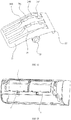
FIG. 1 is a schematic structural view of an indoor unit of an air conditioner according to an embodiment of the present disclosure; -
FIG. 2 is a schematic cross-sectional view of the indoor unit of the air conditioner inFIG. 1 ; -
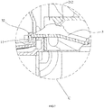
FIG. 3 is a schematic enlarged view of a portion A inFIG. 2 ; -
FIG. 4 is a schematic structural view of a bracket inFIG. 2 ; -
FIG. 5 is a schematic enlarged view of a portion B inFIG. 4 ; -
FIG. 6 is another schematic cross-sectional view of the indoor unit of the air conditioner inFIG. 1 ; -
FIG. 7 is a schematic enlarged view of a portion C inFIG. 6 ; -
FIG. 8 is still another schematic cross-sectional view of the indoor unit of the air conditioner inFIG. 1 ; -
FIG. 9 is a schematic enlarged view of a portion D inFIG. 8 ; -
FIG. 10 is a schematic structural view of an air duct assembly inFIG. 2 ; -
FIG. 11 is a schematic enlarged view of a portion E inFIG. 10 ; -
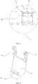
FIG. 12 is a schematic structural view of a first rotating buckle inFIG. 7 ; -
FIG. 13 is a schematic structural view of a face frame inFIG. 2 ; -
FIG. 14 is a schematic enlarged view of a portion F inFIG. 13 ; and -
FIG. 15 is a schematic structural view of a second rotating buckle inFIG. 9 . -
[Table 1] Reference numeral Name Reference numeral Name 1 Chassis 11 Buckle slot 12 Elastic engaging buckle 121 Upper elastic buckle 122 Lower elastic buckle 123 Guiding block 2 Air duct assembly 21 First mounting slot 211 First shaft hole 212 Elastic protrusion 213 Guiding slot 22 Front water receiving tray 221 Engaging portion 23 Rear water receiving tray 231 Engaging slot 24 Sliding shaft 3 First rotating buckle 31 First buckle body 32 First buckle portion 33 First rotating shaft 34 Abutting rib 341 First limiting slot 342 Second limiting slot 343 First protrusion portion 344 Second protrusion 4 Face frame porti on 41 Second mounting slot 411 Second shaft hole 412 Limiting protrusion 5 Second rotating buckle 51 Second buckle body 52 Second buckle portion 53 Second rotating shaft 54 Abutting block 6 Fixing portion 61 Guiding rail 7 Heat exchanger 8 Cross flow wind wheel 9 Panel - The implementation, functional features and advantages of the present application will be further described with reference to the accompanying drawings.
- The technical solutions in the embodiments of the present application are clearly and completely described in the following with reference to the drawings in the embodiments of the present application. It is obvious that the described embodiments are only a part of the embodiments of the present application, and not all of them. All other embodiments obtained by those of ordinary skill in the art based on the embodiments of the present application without creative labor are within the scope of the present application.
- It should be noted that all directional indications (such as up, down, left, right, front, back, ...) in the embodiments of the present application are only used to explain the relative position relation, motion, etc. of each component under a certain posture (as shown in the drawing). If the specific posture changes, the directional indication also changes accordingly.
- In addition, the descriptions of "first", "second", and the like in the present application are used for descriptive purposes only, and are not to be construed as indicating or implying their relative importance or implicitly indicating the number of technical features indicated. Thus, features defining "first" or "second" may include at least one of the features, either explicitly or implicitly. In addition, the technical solutions of the various embodiments may be combined with each other, but must be based on the realization of those skilled in the art, and when the combination of the technical solutions is contradictory or impossible to implement, it should be considered that the combination of the technical solutions does not exist, nor is it within the scope of protection required by the present application.
- The present disclosure provides an indoor unit of an air conditioner.
- In some embodiments of the present disclosure, referring to
FIGS. 1 to 9 , the indoor unit of the air conditioner includes: - a bracket (not shown), which includes a
chassis 1, and a limiting structure is provided at a lower portion of thechassis 1; - an air duct assembly 2, located in front of the
chassis 1, and an upper portion of the air duct assembly 2 is detachably engaged or magnetically connected with an upper portion of thechassis 1; and - a movable limiting member, provided on a lower portion of the air duct assembly 2, where the movable limiting member is configured to be movably protruded from the air duct assembly and engaged with the limiting structure to limit the air duct assembly 2 inside the bracket.
- In this embodiment, the bracket further includes a
face frame 4 located in front of the air duct assembly 2. Apanel 9 of the indoor unit of the air conditioner is installed outside theface frame 4. Structures such as aheat exchanger 7 and a crossflow wind wheel 8 are provided between theface frame 4 and thechassis 1. - Specifically, when disassembling the air duct assembly 2, after opening the
panel 9, the movable limiting member is adjusted in the front-rear direction to separate it from the limiting structure, and then the air duct assembly 2 is pulled down with a certain force (increasing force). When the pull-down force is greater than the engaging force or magnetic attraction force of the upper portion of the air duct assembly 2 and thechassis 1, the upper portion of the air duct assembly 2 is also separated from thechassis 1, so that the air duct assembly 2 is detached from the bracket. - According to the technical solution of the present disclosure, a limiting structure is arranged at the lower portion of the
chassis 1 of the indoor unit of the air conditioner, and the movable limiting member is arranged at the lower portion of the air duct assembly 2, where the movable limiting member is configured to be movably protruded from the air duct assembly and engaged with the limiting structure. It can be understood that, compared with the prior art that the lower portion of the air duct assembly 2 is fixed with screws, this arrangement simplifies the disassembly process of the air duct assembly 2, thereby effectively improving the convenience of maintenance or cleaning of the air duct assembly 2. - Further, the movable limiting member is pivotally connected to the lower portion of the air duct assembly 2 in the left-right direction to rotate back and forth relative to the air duct assembly 2. It can be understood that with such a setting, the limiting and opening of the movable limiting member may be achieved through a simple rotating action, and the operation is convenient and fast, which better improves the convenience for the user to unlock or fix the lower portion of the air duct assembly 2. It should be noted that the design is not limited to this. In other embodiments, the movable limiting member may also be slidably connected to the lower portion of the air duct assembly 2 in the front-rear direction to slide back and forth relative to the air duct assembly 2.
- Further, referring to
FIG. 7 andFIGS. 10 to 12 , the movable limiting member may be a firstrotating buckle 3. The firstrotating buckle 3 includes afirst buckle body 31, which is pivotally connected to the lower portion of the air duct assembly 2 in the left-right direction; and afirst buckle portion 32, which is located at an end of thefirst buckle body 31 adjacent to thechassis 1. The limiting structure is abuckle slot 11 adapted to fit thefirst buckle portion 11. It can be understood that with such a setting, the lower portion of the air duct assembly 2 and thechassis 1 may be fixed through thefirst buckle portion 11 being buckled and matched with thebuckle slot 11, and the structure is simple and the connection is stable. It should be noted that the design is not limited to this. In other embodiments, thebuckle slot 11 may be defined on an end of thefirst buckle body 31 adjacent to thechassis 1, and the limiting structure may be afirst buckle portion 32 adapted to fit thebuckle slot 11. In this embodiment, at least twobuckle slots 11 are arranged at the lower portion of thechassis 1 in the left-right direction. Correspondingly, at least two firstrotating buckles 3 are provided at the lower portion of the air duct assembly 2 to better ensure the fixing stability of the lower portion of the air duct assembly 2. - Further, the lower portion of the air duct assembly 2 includes: a first mounting
slot 21, which penetrates through a wall of the air duct assembly 2 in a front-rear direction. The firstrotating buckle 3 is partially provided in the first mountingslot 21, and a side wall of the first mountingslot 21 includes afirst shaft hole 211 in the left-right direction. The first buckle body includes: a firstrotating shaft 33, which is in clearance fit with thefirst shaft hole 211, and inserted in thefirst shaft hole 211. It can be understood that with such a setting, on the one hand, it can effectively protect the firstrotating buckle 3 and avoid external structures from interfering with the normal operation of the firstrotating buckle 3; on the other hand, the manner in which the shaft hole cooperates with the rotating shaft to realize the pivot connection is widely used in the prior art, so that it has the advantages of simple structure and stable connection. In this embodiment, thefirst buckle body 31 is in convex arc-shaped facing upward, and one firstrotating shaft 33 is respectively provided on both sides of the apex of the convex arc. Correspondingly, onefirst shaft hole 211 corresponding to each firstrotating shaft 33 is respectively provided on two side walls of the first mountingslot 21. A pressing portion for the user to press is defined at an end of thefirst buckle body 31 facing away from thechassis 1. It should be noted that the design is not limited to this. In other embodiments, thefirst buckle body 31 may also be specifically set in other shapes. - Further, the first mounting
slot 21 includes two side walls, and each side wall includes a guidingslot 213 extending rearward and obliquely from a front edge of the each side wall, and a tail end of each guidingslot 213 includes onefirst shaft hole 211. It can be understood that with such a setting, the guidingslot 213 may guide the firstrotating buckle 3 to be assembled into or disassembled from the first mountingslot 21, thereby improving the convenience of replacing or repairing the firstrotating buckle 3. - Further, an
elastic protrusion 212 is protruded downwardly from a top wall of the first mountingslot 21. Anabutting rib 34 is protruded from an upper surface of thefirst buckle body 31, and the abuttingrib 34 includes: a first limitingslot 341, which is recessed on the abuttingrib 34 and faces theelastic protrusion 212; and a second limitingslot 342, which is recessed on the abuttingrib 34 and faces theelastic protrusion 212. The first limitingslot 341 is located in front of the second limitingslot 342. Theelastic protrusion 212 is movably abutted against the abuttingrib 34. Theelastic protrusion 212 is limited by the first limitingslot 341 to keep thefirst buckle portion 32 being engaged with the bucklingslot 11. Theelastic protrusion 212 is limited by the second limitingslot 342 to keep thefirst buckle portion 32 being away from thebuckle slot 11. It can be understood that with such a setting, the limit is kept by theelastic protrusion 212 and the two limiting slots, and the firstrotating shaft 33 is in clearance fit with thesecond shaft hole 411, so that the user may more easily rotate the firstrotating buckle 3. In this embodiment, afirst protrusion portion 343 is protruded from an upper side of the abuttingrib 34, and asecond protrusion portion 344 is also protruded from the upper side of the abuttingrib 34. Thefirst protrusion portion 343 and thesecond protrusion portion 344 are spaced apart in the front-rear direction, and thefirst protrusion portion 343 is located in front of thesecond protrusion portion 344. The first limitingslot 341 is defined between thefirst protrusion portion 343 and thesecond protrusion portion 344, and the second limitingslot 342 is defined at a rear side of thesecond protrusion portion 344. It can be understood that with such a setting, the structures of the first limitingslot 341 and the second limitingslot 342 may be easily and conveniently implemented. In addition, in this embodiment, the top wall of the first mountingslot 21 extends rearwardly to define an extending portion, and a bottom of the extending portion is provided with theelastic protrusion 212. Theelastic protrusion 212 and the abuttingrib 34 are in convex arc-shaped to each other. Certainly, in other embodiments, different states of thefirst buckle portion 32 may be maintained by the friction limit between the firstrotating shaft 33 and thefirst shaft hole 211, which is not limited in this design. - Further, referring to
FIG. 8 ,FIG. 9 , andFIGS. 13 to 15 , a bottom of a frontwater receiving tray 22 of the air duct assembly 2 includes an engagingportion 221, and afront face frame 4 includes a secondrotating buckle 5, which is adapted to fit the engagingportion 221, and pivotally connected to thefront face frame 4 in the left-right direction to rotatably engaged with the engagingportion 221. It can be understood that with such a setting, the front portion of the air duct assembly 2 may be effectively limited and protected, so that the air duct assembly 2 may be prevented from being exposed from the inner cavity of the indoor unit of the air conditioner when the front portion is exposed to excessive downward force. In addition, the rotatable engaging method is convenient for the user to operate, and is beneficial to improving the convenience of the user in disassembling and assembling the air duct assembly 2. It should be noted that this design is not limited to this. In another embodiment, the engagingportion 221 may be provided at the front side of theface frame 4, and the secondrotating buckle 5 adapted to fit the engagingportion 221 may be provided on the frontwater receiving tray 22. The secondrotating buckle 5 may be pivotally connected to the bottom of the frontwater receiving tray 22 in the left-right direction to be rotatably engaged with the engagingportion 221. Certainly, in other embodiments, the front portion of the air duct assembly 2 may be connected to theface frame 4 through other methods. - Further, the second
rotating buckle 5 includes: asecond buckle body 51, and one end of thesecond buckle body 51 is pivotally connected to theface frame 4 in the left-right direction; and asecond buckle portion 52, which is located on a surface of thesecond buckle body 51 facing the air duct assembly 2, and disposed away from a pivot end of thesecond buckle body 51. In this embodiment, thesecond buckle portion 52 is a buckle block protruded from the surface of thesecond buckle body 51, and the engagingportion 221 is an engaging block protruded from the bottom of the frontwater receiving tray 22. The buckle block and the engaging block both have an inclined surface adapted to each other. Certainly, the design is not limited to this. In other embodiments, thesecond buckle portion 52 may be a buckle block protruded from the surface of thesecond buckle body 51, and the engagingportion 221 may also be an engaging slot recessed at the bottom of the frontwater receiving tray 22 and adapted to fit the buckle block. - Further, the
face frame 4 includes: asecond mounting slot 41, which penetrates through a wall of theface frame 4 in the front-rear direction. A side wall of the second mountingslot 41 includes asecond shaft hole 411 in the left-right direction. The second buckle body includes: a secondrotating shaft 53, which is in clearance fit with thesecond shaft hole 411, and inserted in thesecond shaft hole 411. It can be understood that with such a setting, on the one hand, it can effectively protect the secondrotating buckle 5 and avoid external structures from interfering with the normal operation of the secondrotating buckle 5; on the other hand, the manner in which the shaft hole cooperates with the rotating shaft to realize the pivot connection is also widely used in the prior art, so that it has the advantages of simple structure and stable connection. In this embodiment, an abuttingblock 54 is further provided on a surface of thesecond buckle body 51 facing the frontwater receiving tray 22. The abuttingblock 54 is located between thesecond buckle portion 52 and the secondrotating shaft 53 in the up-down direction, so that when thesecond buckle portion 52 is buckled to the engagingportion 221, the abuttingblock 54 may abut against a front surface of the frontwater receiving tray 22 to improve the structural strength of the second bucklingbody 51 at the position. In addition, in this embodiment, two limitingprotrusions 412 are disposed oppositely with each other, and each limitingprotrusion 412 is protruded from an edge at a side of a slot opening of the second mountingslot 41. The two second limitingprotrusions 412 are located in front of thesecond buckle body 51 when thesecond buckle portion 52 is buckled with the engagingportion 221, so that the secondrotating buckle 5 may be prevented from easily being rotated out of the second mountingslot 41 under the action of an external force. It should be noted that the present design is not limited to this. In other embodiments, the second mountingslot 41 may be provided with other limiting structures to prevent the secondrotating buckle 5 from being rotated out easily. - Further, referring to
FIGS. 4 and5 , elastic engaging buckles 12 are provided at an upper portion of thechassis 1 in the left-right direction. Engaging structures are provided at a rear edge of a rearwater receiving tray 23 of the air duct assembly 2 in the left-right direction. The elastic engaging buckles 12 are detachably engaged with the engaging structures. In this embodiment, the elastic buckle 12 includes an upperelastic buckle 121 and a lowerelastic buckle 122 which are spaced in parallel and extend toward the front lower side, and guide blocks 123, which are respectively disposed on both sides of the upperelastic buckle 121 and the lowerelastic buckle 122. The engaging structure is anengaging slot 231 adapted to insert into a gap between the upperelastic buckle 121 and the lowerelastic buckle 122. A bottom end of the upperelastic buckle 121 abuts against an inner wall of theengaging slot 231, and a top end of the lowerelastic buckle 122 abuts against an outer wall of theengaging slot 231. The two guiding blocks 123 are configured to guide theengaging slot 231 to insert into the gap between the upperelastic buckle 121 and the lowerelastic buckle 122. It can be understood that with such a setting, the technical difficulty of the structure may be reduced on the basis of ensuring that the air duct assembly 2 is easy to disassemble, thereby reducing the production cost of thechassis 1. It should be noted that this design is not limited to this, and other engaging structures may be specifically provided between thechassis 1 and the upper portion of the air duct assembly 2, or, thechassis 1 and the upper portion of the air duct assembly 2 may be connected by magnetic attraction. - Further, referring to
FIG. 4 andFIG. 10 , the bracket further includes: two fixingportions 6. Onefixing portion 6 is protruded from a left end of a front side of thechassis 1, and the other fixingportion 6 is protruded from a right end of the front side of thechassis 1. Each fixingportion 6 includes: a first sliding portion, which is provided on an opposite lateral side of each fixingportion 6. The air duct assembly 2 includes: two second sliding portions. One second sliding portion is provided on a left end of the air duct assembly 2, and the other second sliding portion is provided on a right end of the air duct assembly 2. Each first sliding portion and each corresponding second sliding portion are slidably matched in a up-down direction of thechassis 1. In this embodiment, the first sliding portion is a guidingrail 61 extending obliquely from an upper side of the fixingportion 6 toward the front lower side, and the second sliding portion is a slidingshaft 24 slidingly adapted to the guidingrail 61, so that the air duct assembly 2 may be slidingly pushed in or pulled out relative to the inner cavity of the indoor unit of the air conditioner, thereby improving the convenience for users to repair or clean the air duct assembly 2. Certainly, in other embodiments, the second sliding portion may also be a guidingrail 61 extending obliquely from the upper portion of the air duct assembly 2 toward the front lower side, and the first sliding portion may be a slidingshaft 24 slidingly adapted to the guidingrail 61, which is not limited in this design. - The present disclosure further provides an air conditioner, which includes an outdoor unit and an indoor unit. Specific structure of the indoor unit of the air conditioner may refer to the foregoing embodiments. Since the air conditioner adopts all the technical solutions of all the above embodiments, it at least has all the beneficial effects brought by the technical solutions of the foregoing embodiments, which are not described in detail here again.
- The above is only preferred embodiments of the present disclosure, and thus does not limit the scope of the present disclosure, and the equivalent structural transformation made by the content of the specification and the drawings of the present disclosure, or directly/indirectly applied to other related technical fields are all included in the patent protection scope of the present disclosure.
Claims (20)
- An indoor unit of an air conditioner, characterized by comprising:a bracket, comprising:
a chassis, comprising:
a limiting structure;an air duct assembly, located in front of the chassis, and detachably engaged or magnetically connected with the chassis; anda movable limiting member, provided on the air duct assembly, wherein the movable limiting member is configured to be movably protruded from the air duct assembly and engaged with the limiting structure to limit the air duct assembly inside the bracket. - The indoor unit of the air conditioner according to claim 1, characterized in that the movable limiting member is pivotally connected to a lower portion of the air duct assembly in a left-right direction to rotate forwardly and rearwardly with respect to the air duct assembly.
- The indoor unit of the air conditioner according to claim 2, characterized in that:
the movable limiting member is a first rotating buckle, the first rotating buckle comprising:a first buckle body, pivotally connected to the lower portion of the air duct assembly in the left-right direction; anda first buckle portion, located at an end of the first buckle body adjacent to the chassis; and, wherein:
the limiting structure is a buckle slot adapted to fit the first buckle portion. - The indoor unit of the air conditioner according to claim 3, characterized in that:the lower portion of the air duct assembly comprises:
a first mounting slot, penetrating through a wall of the air duct assembly in a front-rear direction, the first rotating buckle being partially provided in the first mounting slot, a side wall of the first mounting slot comprising a first shaft hole in the left-right direction; andthe first buckle body comprises:
a first rotating shaft, matched with the first shaft hole, and inserted in the first shaft hole. - The indoor unit of the air conditioner according to claim 4, characterized in that the first mounting slot comprising two side walls, each side wall comprising a guiding slot extending rearward and obliquely from a front edge of the each side wall, a tail end of each guiding slot comprising one first shaft hole.
- The indoor unit of the air conditioner according to claim 4, characterized by further comprising:an elastic protrusion, protruded downwardly from a top wall of the first mounting slot;an abutting rib, protruded from an upper surface of the first buckle body, and comprising:a first limiting slot, recessed on the abutting rib and facing the elastic protrusion; anda second limiting slot, recessed on the abutting rib and facing the elastic protrusion; and, wherein:
the first limiting slot is located in front of the second limiting slot; and,wherein:the elastic protrusion is movably abutted against the abutting rib;the elastic protrusion is limited by the first limiting slot to keep the first buckle portion being engaged with the buckling slot; andthe elastic protrusion is limited by the second limiting slot to keep the first buckle portion being away from the buckle slot. - The indoor unit of the air conditioner according to claim 6, characterized by further comprising:a first protrusion portion, protruded from an upper side of the abutting rib; anda second protrusion portion, protruded from the upper side of the abutting rib;and, wherein:the first protrusion portion and the second protrusion portion are spaced apart in the front-rear direction, the first protrusion portion being located in front of the second protrusion portion; andthe first limiting slot is defined between the first protrusion portion and the second protrusion portion, the second limiting slot being defined at a rear side of the second protrusion portion.
- The indoor unit of the air conditioner according to claim 1, characterized in that the bracket further comprises:
a face frame, located in front of the air duct assembly, a front side of the air duct assembly being movably engaged with the face frame. - The indoor unit of the air conditioner according to claim 8, characterized in that:a bottom of a water receiving tray in front of the air duct assembly comprises:
an engaging portion; andthe face frame comprises:
a second rotating buckle, adapted to fit the engaging portion, and pivotally connected to the face frame in the left-right direction to rotatably engaged with the engaging portion. - The indoor unit of the air conditioner according to claim 9, characterized in that the second rotating buckle comprises:a second buckle body, one end of the second buckle body being pivotally connected to the face frame in the left-right direction; anda second buckle portion, located on a surface of the second buckle body facing the air duct assembly, and disposed away from a pivot end of the second buckle body.
- The indoor unit of the air conditioner according to claim 10, characterized in that:the face frame comprises:
a second mounting slot, penetrating through a wall of the face frame in the front-rear direction, a side wall of the second mounting slot comprising a second shaft hole in the left-right direction; andthe second buckle body comprises:
a second rotating shaft, matched with the second shaft hole, and inserted in the second shaft hole. - The indoor unit of the air conditioner according to claim 11, characterized by further comprising:
two limiting protrusions, disposed oppositely with each other, each limiting protrusion being protruded from an edge at a side of a slot opening of the second mounting slot; and, wherein:
the two second limiting protrusions are located in front of the second buckle body when the second buckle portion is buckled with the engaging portion. - The indoor unit of the air conditioner according to claim 1, characterized by further comprising:elastic engaging buckles, provided at an upper portion of the chassis in the left-right direction;engaging structures, provided at a rear edge of an upper portion of the air duct assembly in the left-right direction; and, wherein:
the elastic engaging buckles are detachably engaged with the engaging structures. - The indoor unit of the air conditioner according to claim 1, characterized in that:the bracket further comprises:
two fixing portions, one fixing portion being protruded from a left end of a front side of the chassis, the other fixing portion being protruded from a right end of the front side of the chassis, each fixing portion comprising:
a first sliding portion, provided on an opposite lateral side of each fixing portion; andthe air duct assembly comprises:
two second sliding portions, one second sliding portion being provided on a left end of the air duct assembly, the other second sliding portion being provided on a right end of the air duct assembly;and, wherein:
each first sliding portion and each corresponding second sliding portion are slidably matched in a up-down direction of the chassis. - An air conditioner, characterized by comprising:an outdoor unit; andan indoor unit, comprising:
a bracket, comprising:
a chassis, comprising:
a limiting structure;an air duct assembly, located in front of the chassis, and detachably engaged or magnetically connected with the chassis; anda movable limiting member, provided on the air duct assembly, wherein the movable limiting member is configured to be movably protruded from the air duct assembly and engaged with the limiting structure to limit the air duct assembly inside the bracket. - The air conditioner according to claim 15, characterized in that the movable limiting member is pivotally connected to a lower portion of the air duct assembly in a left-right direction to rotate forwardly and rearwardly with respect to the air duct assembly.
- The air conditioner according to claim 16, characterized in that:
the movable limiting member is a first rotating buckle, the first rotating buckle comprising:a first buckle body, pivotally connected to the lower portion of the air duct assembly in the left-right direction; anda first buckle portion, located at an end of the first buckle body adjacent to the chassis; and, wherein:
the limiting structure is a buckle slot adapted to fit the first buckle portion. - The air conditioner according to claim 17, characterized in that:the lower portion of the air duct assembly comprises:
a first mounting slot, penetrating through a wall of the air duct assembly in a front-rear direction, the first rotating buckle being partially provided in the first mounting slot, a side wall of the first mounting slot comprising a first shaft hole in the left-right direction; andthe first buckle body comprises:
a first rotating shaft, matched with the first shaft hole, and inserted in the first shaft hole. - The air conditioner according to claim 15, characterized in that the bracket further comprises:
a face frame, located in front of the air duct assembly, a front side of the air duct assembly being movably engaged with the face frame. - The air conditioner according to claim 19, characterized in that:a bottom of a water receiving tray in front of the air duct assembly comprises:
an engaging portion; andthe face frame comprises:
a second rotating buckle, adapted to fit the engaging portion, and pivotally connected to the face frame in the left-right direction to rotatably engaged with the engaging portion.
Applications Claiming Priority (2)
| Application Number | Priority Date | Filing Date | Title |
|---|---|---|---|
| CN201710870214.8A CN107588519B (en) | 2017-09-21 | 2017-09-21 | Air conditioner indoor unit and air conditioner |
| PCT/CN2018/075281 WO2019056690A1 (en) | 2017-09-21 | 2018-02-05 | Air conditioner indoor unit and air conditioner |
Publications (3)
| Publication Number | Publication Date |
|---|---|
| EP3650763A1 true EP3650763A1 (en) | 2020-05-13 |
| EP3650763A4 EP3650763A4 (en) | 2020-08-19 |
| EP3650763B1 EP3650763B1 (en) | 2023-05-10 |
Family
ID=61048824
Family Applications (1)
| Application Number | Title | Priority Date | Filing Date |
|---|---|---|---|
| EP18857934.6A Active EP3650763B1 (en) | 2017-09-21 | 2018-02-05 | Air conditioner indoor unit |
Country Status (6)
| Country | Link |
|---|---|
| US (1) | US11181295B2 (en) |
| EP (1) | EP3650763B1 (en) |
| JP (1) | JP6902161B2 (en) |
| KR (1) | KR102322590B1 (en) |
| CN (1) | CN107588519B (en) |
| WO (1) | WO2019056690A1 (en) |
Families Citing this family (10)
| Publication number | Priority date | Publication date | Assignee | Title |
|---|---|---|---|---|
| CN107588519B (en) | 2017-09-21 | 2024-04-26 | 广东美的制冷设备有限公司 | Air conditioner indoor unit and air conditioner |
| CN108592198B (en) * | 2018-05-09 | 2021-07-23 | 重庆海尔空调器有限公司 | Air guide member and cabinet-type air conditioner indoor unit having the same |
| CN210128421U (en) * | 2019-05-22 | 2020-03-06 | 广东美的制冷设备有限公司 | Air conditioner indoor unit and air conditioner |
| CN110118432A (en) * | 2019-05-30 | 2019-08-13 | 宁波奥克斯电气股份有限公司 | A kind of panel mounting structure and air conditioner |
| CN113251491B (en) * | 2020-04-30 | 2026-01-23 | 海信(广东)空调有限公司 | Detachable and washable air conditioner indoor unit |
| CN113251477B (en) * | 2020-04-30 | 2025-07-18 | 海信(广东)空调有限公司 | Handle and air conditioner indoor unit |
| JP7411118B2 (en) * | 2020-04-30 | 2024-01-10 | 海信(広東)空調有限公司 | Air conditioning indoor unit that can be disassembled and cleaned |
| CN114383200B (en) * | 2020-10-19 | 2025-04-08 | 宁波奥克斯电气有限公司 | Indoor unit of air conditioner |
| CN114576844B (en) * | 2020-11-30 | 2025-02-18 | 宁波奥克斯电气有限公司 | Air duct mechanism and air conditioner |
| CN215597426U (en) * | 2021-05-28 | 2022-01-21 | 青岛海尔空调器有限总公司 | Air conditioner indoor unit and air conditioner |
Family Cites Families (26)
| Publication number | Priority date | Publication date | Assignee | Title |
|---|---|---|---|---|
| US3878856A (en) * | 1973-04-06 | 1975-04-22 | Jon D Hall | Apparatus for washing glassware |
| JPS5950894B2 (en) * | 1979-02-28 | 1984-12-11 | 松下冷機株式会社 | wall-mounted air conditioner |
| JP2854220B2 (en) * | 1993-07-30 | 1999-02-03 | 三洋電機株式会社 | Air conditioner |
| JP3121505B2 (en) * | 1994-11-02 | 2001-01-09 | 三菱電機株式会社 | Air conditioner |
| JP3122715B2 (en) * | 1996-11-13 | 2001-01-09 | 東芝キヤリア株式会社 | Indoor unit of air conditioner |
| JPH1183110A (en) * | 1997-09-10 | 1999-03-26 | Toshiba Corp | Ceiling ventilation fan |
| JP4281183B2 (en) * | 1999-11-19 | 2009-06-17 | 株式会社富士通ゼネラル | Recessed ceiling air conditioner |
| CN1299079C (en) * | 2002-11-26 | 2007-02-07 | 乐金电子(天津)电器有限公司 | Fixing device for window type air conditioner |
| KR100813325B1 (en) * | 2006-12-08 | 2008-03-12 | 캐리어 주식회사 | Air blower fan module detachable structure |
| JP4698747B2 (en) * | 2009-08-19 | 2011-06-08 | シャープ株式会社 | Wall-mounted air conditioner |
| CN102261700B (en) * | 2011-07-08 | 2015-11-25 | 张鑫珩 | The washable indoor apparatus of air conditioner of a kind of modularized combination type fan |
| CN202521800U (en) * | 2012-03-16 | 2012-11-07 | 广东美的集团芜湖制冷设备有限公司 | Air conditioner screw cap connecting mechanism |
| JP6136540B2 (en) * | 2013-04-30 | 2017-05-31 | ダイキン工業株式会社 | Makeup panel temporary hanging structure of indoor unit of air conditioner |
| KR101579221B1 (en) * | 2013-07-23 | 2015-12-22 | 삼성전자 주식회사 | Indoor unit of air conditioner and method of connecting tube thereof |
| CN204629726U (en) * | 2015-03-27 | 2015-09-09 | 广东美的制冷设备有限公司 | Air conditioner room unit |
| CN104748238B (en) * | 2015-03-31 | 2018-12-18 | 广东美的制冷设备有限公司 | The casing of air conditioner room unit and air conditioner room unit |
| JP6359577B2 (en) * | 2016-02-18 | 2018-07-18 | 三菱重工サーマルシステムズ株式会社 | Air conditioner |
| CN205878343U (en) * | 2016-06-29 | 2017-01-11 | 广东美的制冷设备有限公司 | Wall -mounted type air conditioner indoor machine and chassis assembly spare |
| CN105928078B (en) * | 2016-06-30 | 2019-10-11 | 奥克斯空调股份有限公司 | A kind of wall-hanging indoor unit of air conditioner |
| CN106016468B (en) * | 2016-06-30 | 2022-02-25 | 奥克斯空调股份有限公司 | Wall-mounted air conditioner indoor unit easy to disassemble |
| CN206478740U (en) * | 2017-01-18 | 2017-09-08 | 美的集团武汉制冷设备有限公司 | Indoor apparatus of air conditioner and air conditioner |
| CN107062389B (en) * | 2017-01-18 | 2022-08-26 | 美的集团武汉制冷设备有限公司 | Air conditioner indoor unit and air conditioner |
| CN107036173A (en) * | 2017-06-06 | 2017-08-11 | 美的集团股份有限公司 | Indoor apparatus of air conditioner and air conditioner |
| CN107143924B (en) * | 2017-07-05 | 2019-08-27 | 珠海格力电器股份有限公司 | Indoor unit shell structure and air conditioner indoor unit with same |
| CN207299419U (en) * | 2017-09-21 | 2018-05-01 | 广东美的制冷设备有限公司 | Indoor apparatus of air conditioner and air conditioner |
| CN107588519B (en) * | 2017-09-21 | 2024-04-26 | 广东美的制冷设备有限公司 | Air conditioner indoor unit and air conditioner |
-
2017
- 2017-09-21 CN CN201710870214.8A patent/CN107588519B/en active Active
-
2018
- 2018-02-05 EP EP18857934.6A patent/EP3650763B1/en active Active
- 2018-02-05 WO PCT/CN2018/075281 patent/WO2019056690A1/en not_active Ceased
- 2018-02-05 KR KR1020207005504A patent/KR102322590B1/en active Active
- 2018-02-05 JP JP2020511257A patent/JP6902161B2/en active Active
-
2020
- 2020-03-13 US US16/818,193 patent/US11181295B2/en active Active
Also Published As
| Publication number | Publication date |
|---|---|
| KR102322590B1 (en) | 2021-11-05 |
| CN107588519B (en) | 2024-04-26 |
| US11181295B2 (en) | 2021-11-23 |
| CN107588519A (en) | 2018-01-16 |
| KR20200035287A (en) | 2020-04-02 |
| US20200208870A1 (en) | 2020-07-02 |
| EP3650763B1 (en) | 2023-05-10 |
| JP6902161B2 (en) | 2021-07-14 |
| WO2019056690A1 (en) | 2019-03-28 |
| EP3650763A4 (en) | 2020-08-19 |
| JP2020531784A (en) | 2020-11-05 |
Similar Documents
| Publication | Publication Date | Title |
|---|---|---|
| EP3650763A1 (en) | Air conditioner indoor unit and air conditioner | |
| EP3699501B1 (en) | Wall-mounted indoor air conditioning unit and air conditioner | |
| CN201697414U (en) | Connection structure of hinge on refrigerator door body and refrigerator | |
| CN107702307B (en) | Air deflector mechanism and air conditioner with same | |
| JP5370191B2 (en) | Air conditioner indoor unit | |
| CN106705239A (en) | Wall-mounted air conditioner indoor unit and wall-mounted air conditioner | |
| CN106594880B (en) | Indoor unit of air conditioner | |
| CN203785205U (en) | Air conditioner and its outlet components | |
| CN207763097U (en) | Air conditioner indoor unit and air conditioner | |
| CN205654575U (en) | Tower fan convenient to dismantle and wash | |
| CN106765590A (en) | Indoor apparatus of air conditioner and air-conditioner | |
| CN105890052A (en) | Wall-mounted air-conditioner indoor machine and wall-mounted air-conditioner | |
| CN104913471A (en) | Pipeline installation baffle assembly and air conditioner | |
| CN206387021U (en) | Wall-hanging indoor unit of air conditioner and wall-hanging air conditioner | |
| CN106705242B (en) | Wall-mounted air conditioner indoor unit and wall-mounted air conditioner | |
| CN209944704U (en) | Air conditioner indoor unit easy to disassemble and wash and air conditioner with same | |
| CN209310128U (en) | Air conditioner indoor unit and air conditioner | |
| CN207880981U (en) | Air conditioner indoor unit and air conditioner | |
| CN206478819U (en) | Indoor apparatus of air conditioner | |
| CN206420058U (en) | Wall-hanging indoor unit of air conditioner and wall-hanging air conditioner | |
| CN206469357U (en) | Indoor apparatus of air conditioner and air conditioner | |
| CN215175466U (en) | Shell assembly and duct machine | |
| CN108006833B (en) | Air conditioning cabinets and air conditioners | |
| CN214501426U (en) | Air deflector and air conditioner | |
| CN220269510U (en) | Air deflector structure and air conditioner |
Legal Events
| Date | Code | Title | Description |
|---|---|---|---|
| STAA | Information on the status of an ep patent application or granted ep patent |
Free format text: STATUS: THE INTERNATIONAL PUBLICATION HAS BEEN MADE |
|
| PUAI | Public reference made under article 153(3) epc to a published international application that has entered the european phase |
Free format text: ORIGINAL CODE: 0009012 |
|
| STAA | Information on the status of an ep patent application or granted ep patent |
Free format text: STATUS: REQUEST FOR EXAMINATION WAS MADE |
|
| 17P | Request for examination filed |
Effective date: 20200204 |
|
| AK | Designated contracting states |
Kind code of ref document: A1 Designated state(s): AL AT BE BG CH CY CZ DE DK EE ES FI FR GB GR HR HU IE IS IT LI LT LU LV MC MK MT NL NO PL PT RO RS SE SI SK SM TR |
|
| AX | Request for extension of the european patent |
Extension state: BA ME |
|
| A4 | Supplementary search report drawn up and despatched |
Effective date: 20200720 |
|
| RIC1 | Information provided on ipc code assigned before grant |
Ipc: F24F 13/20 20060101ALI20200714BHEP Ipc: F24F 13/32 20060101ALI20200714BHEP Ipc: F24F 1/0007 20190101ALI20200714BHEP Ipc: F24F 1/0057 20190101ALI20200714BHEP Ipc: F24F 1/00 20190101AFI20200714BHEP Ipc: F24F 13/02 20060101ALI20200714BHEP |
|
| DAV | Request for validation of the european patent (deleted) | ||
| DAX | Request for extension of the european patent (deleted) | ||
| RAP3 | Party data changed (applicant data changed or rights of an application transferred) |
Owner name: MIDEA GROUP CO., LTD. Owner name: GD MIDEA AIR-CONDITIONING EQUIPMENT CO., LTD. |
|
| STAA | Information on the status of an ep patent application or granted ep patent |
Free format text: STATUS: EXAMINATION IS IN PROGRESS |
|
| 17Q | First examination report despatched |
Effective date: 20220311 |
|
| GRAP | Despatch of communication of intention to grant a patent |
Free format text: ORIGINAL CODE: EPIDOSNIGR1 |
|
| STAA | Information on the status of an ep patent application or granted ep patent |
Free format text: STATUS: GRANT OF PATENT IS INTENDED |
|
| INTG | Intention to grant announced |
Effective date: 20230228 |
|
| GRAS | Grant fee paid |
Free format text: ORIGINAL CODE: EPIDOSNIGR3 |
|
| GRAA | (expected) grant |
Free format text: ORIGINAL CODE: 0009210 |
|
| STAA | Information on the status of an ep patent application or granted ep patent |
Free format text: STATUS: THE PATENT HAS BEEN GRANTED |
|
| AK | Designated contracting states |
Kind code of ref document: B1 Designated state(s): AL AT BE BG CH CY CZ DE DK EE ES FI FR GB GR HR HU IE IS IT LI LT LU LV MC MK MT NL NO PL PT RO RS SE SI SK SM TR |
|
| REG | Reference to a national code |
Ref country code: GB Ref legal event code: FG4D |
|
| REG | Reference to a national code |
Ref country code: AT Ref legal event code: REF Ref document number: 1567000 Country of ref document: AT Kind code of ref document: T Effective date: 20230515 Ref country code: CH Ref legal event code: EP |
|
| REG | Reference to a national code |
Ref country code: DE Ref legal event code: R096 Ref document number: 602018049797 Country of ref document: DE |
|
| REG | Reference to a national code |
Ref country code: IE Ref legal event code: FG4D |
|
| REG | Reference to a national code |
Ref country code: LT Ref legal event code: MG9D |
|
| REG | Reference to a national code |
Ref country code: NL Ref legal event code: MP Effective date: 20230510 |
|
| REG | Reference to a national code |
Ref country code: AT Ref legal event code: MK05 Ref document number: 1567000 Country of ref document: AT Kind code of ref document: T Effective date: 20230510 |
|
| PG25 | Lapsed in a contracting state [announced via postgrant information from national office to epo] |
Ref country code: SE Free format text: LAPSE BECAUSE OF FAILURE TO SUBMIT A TRANSLATION OF THE DESCRIPTION OR TO PAY THE FEE WITHIN THE PRESCRIBED TIME-LIMIT Effective date: 20230510 Ref country code: PT Free format text: LAPSE BECAUSE OF FAILURE TO SUBMIT A TRANSLATION OF THE DESCRIPTION OR TO PAY THE FEE WITHIN THE PRESCRIBED TIME-LIMIT Effective date: 20230911 Ref country code: NO Free format text: LAPSE BECAUSE OF FAILURE TO SUBMIT A TRANSLATION OF THE DESCRIPTION OR TO PAY THE FEE WITHIN THE PRESCRIBED TIME-LIMIT Effective date: 20230810 Ref country code: NL Free format text: LAPSE BECAUSE OF FAILURE TO SUBMIT A TRANSLATION OF THE DESCRIPTION OR TO PAY THE FEE WITHIN THE PRESCRIBED TIME-LIMIT Effective date: 20230510 Ref country code: ES Free format text: LAPSE BECAUSE OF FAILURE TO SUBMIT A TRANSLATION OF THE DESCRIPTION OR TO PAY THE FEE WITHIN THE PRESCRIBED TIME-LIMIT Effective date: 20230510 Ref country code: AT Free format text: LAPSE BECAUSE OF FAILURE TO SUBMIT A TRANSLATION OF THE DESCRIPTION OR TO PAY THE FEE WITHIN THE PRESCRIBED TIME-LIMIT Effective date: 20230510 |
|
| PG25 | Lapsed in a contracting state [announced via postgrant information from national office to epo] |
Ref country code: RS Free format text: LAPSE BECAUSE OF FAILURE TO SUBMIT A TRANSLATION OF THE DESCRIPTION OR TO PAY THE FEE WITHIN THE PRESCRIBED TIME-LIMIT Effective date: 20230510 Ref country code: PL Free format text: LAPSE BECAUSE OF FAILURE TO SUBMIT A TRANSLATION OF THE DESCRIPTION OR TO PAY THE FEE WITHIN THE PRESCRIBED TIME-LIMIT Effective date: 20230510 Ref country code: LV Free format text: LAPSE BECAUSE OF FAILURE TO SUBMIT A TRANSLATION OF THE DESCRIPTION OR TO PAY THE FEE WITHIN THE PRESCRIBED TIME-LIMIT Effective date: 20230510 Ref country code: LT Free format text: LAPSE BECAUSE OF FAILURE TO SUBMIT A TRANSLATION OF THE DESCRIPTION OR TO PAY THE FEE WITHIN THE PRESCRIBED TIME-LIMIT Effective date: 20230510 Ref country code: IS Free format text: LAPSE BECAUSE OF FAILURE TO SUBMIT A TRANSLATION OF THE DESCRIPTION OR TO PAY THE FEE WITHIN THE PRESCRIBED TIME-LIMIT Effective date: 20230910 Ref country code: HR Free format text: LAPSE BECAUSE OF FAILURE TO SUBMIT A TRANSLATION OF THE DESCRIPTION OR TO PAY THE FEE WITHIN THE PRESCRIBED TIME-LIMIT Effective date: 20230510 Ref country code: GR Free format text: LAPSE BECAUSE OF FAILURE TO SUBMIT A TRANSLATION OF THE DESCRIPTION OR TO PAY THE FEE WITHIN THE PRESCRIBED TIME-LIMIT Effective date: 20230811 |
|
| PG25 | Lapsed in a contracting state [announced via postgrant information from national office to epo] |
Ref country code: FI Free format text: LAPSE BECAUSE OF FAILURE TO SUBMIT A TRANSLATION OF THE DESCRIPTION OR TO PAY THE FEE WITHIN THE PRESCRIBED TIME-LIMIT Effective date: 20230510 |
|
| PG25 | Lapsed in a contracting state [announced via postgrant information from national office to epo] |
Ref country code: SK Free format text: LAPSE BECAUSE OF FAILURE TO SUBMIT A TRANSLATION OF THE DESCRIPTION OR TO PAY THE FEE WITHIN THE PRESCRIBED TIME-LIMIT Effective date: 20230510 |
|
| PG25 | Lapsed in a contracting state [announced via postgrant information from national office to epo] |
Ref country code: SM Free format text: LAPSE BECAUSE OF FAILURE TO SUBMIT A TRANSLATION OF THE DESCRIPTION OR TO PAY THE FEE WITHIN THE PRESCRIBED TIME-LIMIT Effective date: 20230510 Ref country code: SK Free format text: LAPSE BECAUSE OF FAILURE TO SUBMIT A TRANSLATION OF THE DESCRIPTION OR TO PAY THE FEE WITHIN THE PRESCRIBED TIME-LIMIT Effective date: 20230510 Ref country code: RO Free format text: LAPSE BECAUSE OF FAILURE TO SUBMIT A TRANSLATION OF THE DESCRIPTION OR TO PAY THE FEE WITHIN THE PRESCRIBED TIME-LIMIT Effective date: 20230510 Ref country code: EE Free format text: LAPSE BECAUSE OF FAILURE TO SUBMIT A TRANSLATION OF THE DESCRIPTION OR TO PAY THE FEE WITHIN THE PRESCRIBED TIME-LIMIT Effective date: 20230510 Ref country code: DK Free format text: LAPSE BECAUSE OF FAILURE TO SUBMIT A TRANSLATION OF THE DESCRIPTION OR TO PAY THE FEE WITHIN THE PRESCRIBED TIME-LIMIT Effective date: 20230510 Ref country code: CZ Free format text: LAPSE BECAUSE OF FAILURE TO SUBMIT A TRANSLATION OF THE DESCRIPTION OR TO PAY THE FEE WITHIN THE PRESCRIBED TIME-LIMIT Effective date: 20230510 |
|
| REG | Reference to a national code |
Ref country code: DE Ref legal event code: R097 Ref document number: 602018049797 Country of ref document: DE |
|
| PLBE | No opposition filed within time limit |
Free format text: ORIGINAL CODE: 0009261 |
|
| STAA | Information on the status of an ep patent application or granted ep patent |
Free format text: STATUS: NO OPPOSITION FILED WITHIN TIME LIMIT |
|
| 26N | No opposition filed |
Effective date: 20240213 |
|
| PG25 | Lapsed in a contracting state [announced via postgrant information from national office to epo] |
Ref country code: SI Free format text: LAPSE BECAUSE OF FAILURE TO SUBMIT A TRANSLATION OF THE DESCRIPTION OR TO PAY THE FEE WITHIN THE PRESCRIBED TIME-LIMIT Effective date: 20230510 |
|
| PG25 | Lapsed in a contracting state [announced via postgrant information from national office to epo] |
Ref country code: SI Free format text: LAPSE BECAUSE OF FAILURE TO SUBMIT A TRANSLATION OF THE DESCRIPTION OR TO PAY THE FEE WITHIN THE PRESCRIBED TIME-LIMIT Effective date: 20230510 |
|
| REG | Reference to a national code |
Ref country code: DE Ref legal event code: R119 Ref document number: 602018049797 Country of ref document: DE |
|
| PG25 | Lapsed in a contracting state [announced via postgrant information from national office to epo] |
Ref country code: MC Free format text: LAPSE BECAUSE OF FAILURE TO SUBMIT A TRANSLATION OF THE DESCRIPTION OR TO PAY THE FEE WITHIN THE PRESCRIBED TIME-LIMIT Effective date: 20230510 |
|
| REG | Reference to a national code |
Ref country code: CH Ref legal event code: PL |
|
| PG25 | Lapsed in a contracting state [announced via postgrant information from national office to epo] |
Ref country code: LU Free format text: LAPSE BECAUSE OF NON-PAYMENT OF DUE FEES Effective date: 20240205 |
|
| PG25 | Lapsed in a contracting state [announced via postgrant information from national office to epo] |
Ref country code: CH Free format text: LAPSE BECAUSE OF NON-PAYMENT OF DUE FEES Effective date: 20240229 |
|
| GBPC | Gb: european patent ceased through non-payment of renewal fee |
Effective date: 20240205 |
|
| PG25 | Lapsed in a contracting state [announced via postgrant information from national office to epo] |
Ref country code: LU Free format text: LAPSE BECAUSE OF NON-PAYMENT OF DUE FEES Effective date: 20240205 Ref country code: CH Free format text: LAPSE BECAUSE OF NON-PAYMENT OF DUE FEES Effective date: 20240229 |
|
| PG25 | Lapsed in a contracting state [announced via postgrant information from national office to epo] |
Ref country code: BG Free format text: LAPSE BECAUSE OF FAILURE TO SUBMIT A TRANSLATION OF THE DESCRIPTION OR TO PAY THE FEE WITHIN THE PRESCRIBED TIME-LIMIT Effective date: 20230510 |
|
| PG25 | Lapsed in a contracting state [announced via postgrant information from national office to epo] |
Ref country code: BG Free format text: LAPSE BECAUSE OF FAILURE TO SUBMIT A TRANSLATION OF THE DESCRIPTION OR TO PAY THE FEE WITHIN THE PRESCRIBED TIME-LIMIT Effective date: 20230510 |
|
| REG | Reference to a national code |
Ref country code: BE Ref legal event code: MM Effective date: 20240229 |
|
| PG25 | Lapsed in a contracting state [announced via postgrant information from national office to epo] |
Ref country code: DE Free format text: LAPSE BECAUSE OF NON-PAYMENT OF DUE FEES Effective date: 20240903 |
|
| PG25 | Lapsed in a contracting state [announced via postgrant information from national office to epo] |
Ref country code: BE Free format text: LAPSE BECAUSE OF NON-PAYMENT OF DUE FEES Effective date: 20240229 |
|
| PG25 | Lapsed in a contracting state [announced via postgrant information from national office to epo] |
Ref country code: GB Free format text: LAPSE BECAUSE OF NON-PAYMENT OF DUE FEES Effective date: 20240205 |
|
| PG25 | Lapsed in a contracting state [announced via postgrant information from national office to epo] |
Ref country code: IE Free format text: LAPSE BECAUSE OF NON-PAYMENT OF DUE FEES Effective date: 20240205 |
|
| PG25 | Lapsed in a contracting state [announced via postgrant information from national office to epo] |
Ref country code: IE Free format text: LAPSE BECAUSE OF NON-PAYMENT OF DUE FEES Effective date: 20240205 Ref country code: GB Free format text: LAPSE BECAUSE OF NON-PAYMENT OF DUE FEES Effective date: 20240205 Ref country code: DE Free format text: LAPSE BECAUSE OF NON-PAYMENT OF DUE FEES Effective date: 20240903 Ref country code: BE Free format text: LAPSE BECAUSE OF NON-PAYMENT OF DUE FEES Effective date: 20240229 |
|
| PG25 | Lapsed in a contracting state [announced via postgrant information from national office to epo] |
Ref country code: CY Free format text: LAPSE BECAUSE OF FAILURE TO SUBMIT A TRANSLATION OF THE DESCRIPTION OR TO PAY THE FEE WITHIN THE PRESCRIBED TIME-LIMIT; INVALID AB INITIO Effective date: 20180205 |
|
| PG25 | Lapsed in a contracting state [announced via postgrant information from national office to epo] |
Ref country code: HU Free format text: LAPSE BECAUSE OF FAILURE TO SUBMIT A TRANSLATION OF THE DESCRIPTION OR TO PAY THE FEE WITHIN THE PRESCRIBED TIME-LIMIT; INVALID AB INITIO Effective date: 20180205 |
|
| PG25 | Lapsed in a contracting state [announced via postgrant information from national office to epo] |
Ref country code: TR Free format text: LAPSE BECAUSE OF FAILURE TO SUBMIT A TRANSLATION OF THE DESCRIPTION OR TO PAY THE FEE WITHIN THE PRESCRIBED TIME-LIMIT Effective date: 20230510 |
|
| PGFP | Annual fee paid to national office [announced via postgrant information from national office to epo] |
Ref country code: IT Payment date: 20260223 Year of fee payment: 9 |
|
| PGFP | Annual fee paid to national office [announced via postgrant information from national office to epo] |
Ref country code: FR Payment date: 20260224 Year of fee payment: 9 |