EP3650746A1 - Light-emitting device, lighting device, and optical member - Google Patents
Light-emitting device, lighting device, and optical member Download PDFInfo
- Publication number
- EP3650746A1 EP3650746A1 EP19205867.5A EP19205867A EP3650746A1 EP 3650746 A1 EP3650746 A1 EP 3650746A1 EP 19205867 A EP19205867 A EP 19205867A EP 3650746 A1 EP3650746 A1 EP 3650746A1
- Authority
- EP
- European Patent Office
- Prior art keywords
- light
- emitting elements
- emitting
- guide portion
- circuit
- Prior art date
- Legal status (The legal status is an assumption and is not a legal conclusion. Google has not performed a legal analysis and makes no representation as to the accuracy of the status listed.)
- Granted
Links
Images





Classifications
-
- G—PHYSICS
- G02—OPTICS
- G02B—OPTICAL ELEMENTS, SYSTEMS OR APPARATUS
- G02B19/00—Condensers, e.g. light collectors or similar non-imaging optics
- G02B19/0004—Condensers, e.g. light collectors or similar non-imaging optics characterised by the optical means employed
- G02B19/0028—Condensers, e.g. light collectors or similar non-imaging optics characterised by the optical means employed refractive and reflective surfaces, e.g. non-imaging catadioptric systems
-
- H—ELECTRICITY
- H05—ELECTRIC TECHNIQUES NOT OTHERWISE PROVIDED FOR
- H05B—ELECTRIC HEATING; ELECTRIC LIGHT SOURCES NOT OTHERWISE PROVIDED FOR; CIRCUIT ARRANGEMENTS FOR ELECTRIC LIGHT SOURCES, IN GENERAL
- H05B45/00—Circuit arrangements for operating light-emitting diodes [LED]
- H05B45/20—Controlling the colour of the light
-
- F—MECHANICAL ENGINEERING; LIGHTING; HEATING; WEAPONS; BLASTING
- F21—LIGHTING
- F21K—NON-ELECTRIC LIGHT SOURCES USING LUMINESCENCE; LIGHT SOURCES USING ELECTROCHEMILUMINESCENCE; LIGHT SOURCES USING CHARGES OF COMBUSTIBLE MATERIAL; LIGHT SOURCES USING SEMICONDUCTOR DEVICES AS LIGHT-GENERATING ELEMENTS; LIGHT SOURCES NOT OTHERWISE PROVIDED FOR
- F21K9/00—Light sources using semiconductor devices as light-generating elements, e.g. using light-emitting diodes [LED] or lasers
- F21K9/20—Light sources comprising attachment means
- F21K9/23—Retrofit light sources for lighting devices with a single fitting for each light source, e.g. for substitution of incandescent lamps with bayonet or threaded fittings
- F21K9/237—Details of housings or cases, i.e. the parts between the light-generating element and the bases; Arrangement of components within housings or cases
-
- F—MECHANICAL ENGINEERING; LIGHTING; HEATING; WEAPONS; BLASTING
- F21—LIGHTING
- F21K—NON-ELECTRIC LIGHT SOURCES USING LUMINESCENCE; LIGHT SOURCES USING ELECTROCHEMILUMINESCENCE; LIGHT SOURCES USING CHARGES OF COMBUSTIBLE MATERIAL; LIGHT SOURCES USING SEMICONDUCTOR DEVICES AS LIGHT-GENERATING ELEMENTS; LIGHT SOURCES NOT OTHERWISE PROVIDED FOR
- F21K9/00—Light sources using semiconductor devices as light-generating elements, e.g. using light-emitting diodes [LED] or lasers
- F21K9/20—Light sources comprising attachment means
- F21K9/27—Retrofit light sources for lighting devices with two fittings for each light source, e.g. for substitution of fluorescent tubes
- F21K9/278—Arrangement or mounting of circuit elements integrated in the light source
-
- F—MECHANICAL ENGINEERING; LIGHTING; HEATING; WEAPONS; BLASTING
- F21—LIGHTING
- F21K—NON-ELECTRIC LIGHT SOURCES USING LUMINESCENCE; LIGHT SOURCES USING ELECTROCHEMILUMINESCENCE; LIGHT SOURCES USING CHARGES OF COMBUSTIBLE MATERIAL; LIGHT SOURCES USING SEMICONDUCTOR DEVICES AS LIGHT-GENERATING ELEMENTS; LIGHT SOURCES NOT OTHERWISE PROVIDED FOR
- F21K9/00—Light sources using semiconductor devices as light-generating elements, e.g. using light-emitting diodes [LED] or lasers
- F21K9/60—Optical arrangements integrated in the light source, e.g. for improving the colour rendering index or the light extraction
- F21K9/61—Optical arrangements integrated in the light source, e.g. for improving the colour rendering index or the light extraction using light guides
-
- F—MECHANICAL ENGINEERING; LIGHTING; HEATING; WEAPONS; BLASTING
- F21—LIGHTING
- F21K—NON-ELECTRIC LIGHT SOURCES USING LUMINESCENCE; LIGHT SOURCES USING ELECTROCHEMILUMINESCENCE; LIGHT SOURCES USING CHARGES OF COMBUSTIBLE MATERIAL; LIGHT SOURCES USING SEMICONDUCTOR DEVICES AS LIGHT-GENERATING ELEMENTS; LIGHT SOURCES NOT OTHERWISE PROVIDED FOR
- F21K9/00—Light sources using semiconductor devices as light-generating elements, e.g. using light-emitting diodes [LED] or lasers
- F21K9/60—Optical arrangements integrated in the light source, e.g. for improving the colour rendering index or the light extraction
- F21K9/69—Details of refractors forming part of the light source
-
- F—MECHANICAL ENGINEERING; LIGHTING; HEATING; WEAPONS; BLASTING
- F21—LIGHTING
- F21S—NON-PORTABLE LIGHTING DEVICES; SYSTEMS THEREOF; VEHICLE LIGHTING DEVICES SPECIALLY ADAPTED FOR VEHICLE EXTERIORS
- F21S8/00—Lighting devices intended for fixed installation
- F21S8/04—Lighting devices intended for fixed installation intended only for mounting on a ceiling or the like overhead structures
-
- F—MECHANICAL ENGINEERING; LIGHTING; HEATING; WEAPONS; BLASTING
- F21—LIGHTING
- F21V—FUNCTIONAL FEATURES OR DETAILS OF LIGHTING DEVICES OR SYSTEMS THEREOF; STRUCTURAL COMBINATIONS OF LIGHTING DEVICES WITH OTHER ARTICLES, NOT OTHERWISE PROVIDED FOR
- F21V23/00—Arrangement of electric circuit elements in or on lighting devices
- F21V23/04—Arrangement of electric circuit elements in or on lighting devices the elements being switches
-
- F—MECHANICAL ENGINEERING; LIGHTING; HEATING; WEAPONS; BLASTING
- F21—LIGHTING
- F21V—FUNCTIONAL FEATURES OR DETAILS OF LIGHTING DEVICES OR SYSTEMS THEREOF; STRUCTURAL COMBINATIONS OF LIGHTING DEVICES WITH OTHER ARTICLES, NOT OTHERWISE PROVIDED FOR
- F21V5/00—Refractors for light sources
- F21V5/04—Refractors for light sources of lens shape
- F21V5/045—Refractors for light sources of lens shape the lens having discontinuous faces, e.g. Fresnel lenses
-
- F—MECHANICAL ENGINEERING; LIGHTING; HEATING; WEAPONS; BLASTING
- F21—LIGHTING
- F21V—FUNCTIONAL FEATURES OR DETAILS OF LIGHTING DEVICES OR SYSTEMS THEREOF; STRUCTURAL COMBINATIONS OF LIGHTING DEVICES WITH OTHER ARTICLES, NOT OTHERWISE PROVIDED FOR
- F21V5/00—Refractors for light sources
- F21V5/04—Refractors for light sources of lens shape
- F21V5/046—Refractors for light sources of lens shape the lens having a rotationally symmetrical shape about an axis for transmitting light in a direction mainly perpendicular to this axis, e.g. ring or annular lens with light source disposed inside the ring
-
- F—MECHANICAL ENGINEERING; LIGHTING; HEATING; WEAPONS; BLASTING
- F21—LIGHTING
- F21V—FUNCTIONAL FEATURES OR DETAILS OF LIGHTING DEVICES OR SYSTEMS THEREOF; STRUCTURAL COMBINATIONS OF LIGHTING DEVICES WITH OTHER ARTICLES, NOT OTHERWISE PROVIDED FOR
- F21V7/00—Reflectors for light sources
- F21V7/04—Optical design
-
- G—PHYSICS
- G02—OPTICS
- G02B—OPTICAL ELEMENTS, SYSTEMS OR APPARATUS
- G02B19/00—Condensers, e.g. light collectors or similar non-imaging optics
- G02B19/0033—Condensers, e.g. light collectors or similar non-imaging optics characterised by the use
- G02B19/0047—Condensers, e.g. light collectors or similar non-imaging optics characterised by the use for use with a light source
- G02B19/0061—Condensers, e.g. light collectors or similar non-imaging optics characterised by the use for use with a light source the light source comprising a LED
- G02B19/0066—Condensers, e.g. light collectors or similar non-imaging optics characterised by the use for use with a light source the light source comprising a LED in the form of an LED array
-
- H—ELECTRICITY
- H05—ELECTRIC TECHNIQUES NOT OTHERWISE PROVIDED FOR
- H05B—ELECTRIC HEATING; ELECTRIC LIGHT SOURCES NOT OTHERWISE PROVIDED FOR; CIRCUIT ARRANGEMENTS FOR ELECTRIC LIGHT SOURCES, IN GENERAL
- H05B45/00—Circuit arrangements for operating light-emitting diodes [LED]
- H05B45/40—Details of LED load circuits
-
- F—MECHANICAL ENGINEERING; LIGHTING; HEATING; WEAPONS; BLASTING
- F21—LIGHTING
- F21V—FUNCTIONAL FEATURES OR DETAILS OF LIGHTING DEVICES OR SYSTEMS THEREOF; STRUCTURAL COMBINATIONS OF LIGHTING DEVICES WITH OTHER ARTICLES, NOT OTHERWISE PROVIDED FOR
- F21V2200/00—Use of light guides, e.g. fibre optic devices, in lighting devices or systems
-
- F—MECHANICAL ENGINEERING; LIGHTING; HEATING; WEAPONS; BLASTING
- F21—LIGHTING
- F21V—FUNCTIONAL FEATURES OR DETAILS OF LIGHTING DEVICES OR SYSTEMS THEREOF; STRUCTURAL COMBINATIONS OF LIGHTING DEVICES WITH OTHER ARTICLES, NOT OTHERWISE PROVIDED FOR
- F21V7/00—Reflectors for light sources
- F21V7/0091—Reflectors for light sources using total internal reflection
-
- F—MECHANICAL ENGINEERING; LIGHTING; HEATING; WEAPONS; BLASTING
- F21—LIGHTING
- F21Y—INDEXING SCHEME ASSOCIATED WITH SUBCLASSES F21K, F21L, F21S and F21V, RELATING TO THE FORM OR THE KIND OF THE LIGHT SOURCES OR OF THE COLOUR OF THE LIGHT EMITTED
- F21Y2105/00—Planar light sources
- F21Y2105/10—Planar light sources comprising a two-dimensional [2D] array of point-like light-generating elements
- F21Y2105/14—Planar light sources comprising a two-dimensional [2D] array of point-like light-generating elements characterised by the overall shape of the two-dimensional [2D] array
- F21Y2105/18—Planar light sources comprising a two-dimensional [2D] array of point-like light-generating elements characterised by the overall shape of the two-dimensional [2D] array annular; polygonal other than square or rectangular, e.g. for spotlights or for generating an axially symmetrical light beam
-
- F—MECHANICAL ENGINEERING; LIGHTING; HEATING; WEAPONS; BLASTING
- F21—LIGHTING
- F21Y—INDEXING SCHEME ASSOCIATED WITH SUBCLASSES F21K, F21L, F21S and F21V, RELATING TO THE FORM OR THE KIND OF THE LIGHT SOURCES OR OF THE COLOUR OF THE LIGHT EMITTED
- F21Y2115/00—Light-generating elements of semiconductor light sources
- F21Y2115/10—Light-emitting diodes [LED]
-
- G—PHYSICS
- G02—OPTICS
- G02B—OPTICAL ELEMENTS, SYSTEMS OR APPARATUS
- G02B27/00—Optical systems or apparatus not provided for by any of the groups G02B1/00 - G02B26/00, G02B30/00
- G02B27/42—Diffraction optics, i.e. systems including a diffractive element being designed for providing a diffractive effect
- G02B27/4233—Diffraction optics, i.e. systems including a diffractive element being designed for providing a diffractive effect having a diffractive element [DOE] contributing to a non-imaging application
- G02B27/425—Diffraction optics, i.e. systems including a diffractive element being designed for providing a diffractive effect having a diffractive element [DOE] contributing to a non-imaging application in illumination systems
Definitions
- Embodiments relate to a light-emitting device, a lighting device and an optical member.
- a lighting device that can switch the light distribution angle is desirable. For example, it is desirable for one lighting device to illuminate an entire room by increasing the light distribution angle for one condition, and to illuminate a narrow area by reducing the light distribution angle for another condition. To realize such a lighting device, it may be considered to use mechanical means to change the positional relationship of a light source and an optical system.
- a lighting device in which such mechanical means is provided is undesirably large and expensive, needs time to switch, and has poor interior-stylishness.
- a light-emitting device includes one or more first light-emitting elements, one or more second light-emitting elements, and an optical member including a first light condenser portion, a second light condenser portion, and a first light guide portion.
- the first light condenser portion is disposed at a position corresponding to the first light-emitting element.
- the first light condenser portion condenses a portion of light emitted from the first light-emitting element.
- the second light condenser portion surrounds the first light condenser portion.
- the second light condenser portion condenses a portion of the light that is not incident to the first light condenser portion among the light emitted from the first light-emitting element.
- the first light guide portion surrounds the second light condenser portion and at a position corresponding to the second light-emitting element.
- the first light guide portion guides light emitted from the second light-emitting element by causing total reflection in an interior of the first light guide portion.
- a full width at half maximum of light exiting from the first light guide portion is larger than a full width at half maximum of light exiting from the first light condenser portion.
- a light-emitting device includes an optical member including a first light condenser portion, a second light condenser portion, a first light guide portion, one or more first light-emitting elements, and one or more second light-emitting elements.
- the first light condenser portion has a convex lens.
- the second light condenser portion surrounds the first light condenser portion.
- the second light condenser portion has an inner surface and an outer surface being curved outward as approaching a light exiting surface, while being disposed at a periphery of the first light condenser portion.
- the first light guide portion has a tubular configuration surrounding a periphery of the second light condenser portion in an annular configuration.
- the one or more first light-emitting elements are disposed at a position corresponding to the first light condenser portion.
- the one or more second light-emitting elements are disposed at a position corresponding to the first light guide portion.
- An optical member includes a first light condenser portion condensing light incident on a first light incident region, a second light condenser portion surrounding the first light condenser portion, and a first light guide portion surrounding the second light condenser portion.
- the second light condenser portion condenses a portion of the light that is not incident to the first light condenser portion and outputs from a position facing the first light incident region
- the first light guide portion guides light emitted from the second light-emitting element by causing total reflection in an interior of the first light guide portion.
- a full width at half maximum of light exiting from the first light guide portion is larger than a full width at half maximum of light exiting from the first light condenser portion.
- An optical member includes a first light condenser portion, a second light condenser portion having an inner surface and an outer surface being curved outward as approaching a light exiting surface, the second light condenser portion surrounding the first light condenser portion; and a first light guide portion having a tubular configuration surrounding a periphery of the second light condenser portion in an annular configuration.
- a light-emitting circuit includes one or more first light-emitting elements disposed in a first region, and one or more second light-emitting elements surrounding the first region. A color temperature of light emitted from the second light-emitting element is different from a color temperature of light emitted from the first light-emitting element.
- a first circuit and a second circuit are connected in parallel to each other. The first circuit includes the one or more first light-emitting elements. The second circuit includes the one or more second light-emitting elements. A number of stages of the first light-emitting elements connected in series in the first circuit is less than a number of stages of the second light-emitting elements connected in series in the second circuit.
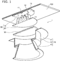
- FIG. 1 is an exploded perspective end view showing a lighting device according to an embodiment.
- FIG. 2A is an end view showing the lighting device according to the present embodiment.
- FIG. 2B is a perspective view showing the lighting device according to the present embodiment.
- the lighting device 1 includes a light source portion 10, an optical member 20, a diffuser plate 30, and a cover member 40.
- a light-emitting device 50 includes the light source portion 10 and the optical member 20.
- the light source portion 10 includes one or more first light-emitting elements 11 and one or more second light-emitting elements 12.
- the optical member 20 includes a first light condenser 22, a second light condenser 23, and a first light guide portion 24.
- the first light condenser 22 is disposed at a position corresponding to the first light-emitting element 11, and condenses the light incident from the first light-emitting element 11.
- the second light condenser 23 surrounds the first light condenser 22, and condenses light emitted from the first light-emitting element 11 and not incident on the first light condenser 22.
- the first light guide portion 24 is disposed at a position corresponding to the second light-emitting element 12 while surrounding the second light condenser 23, and guides the light incident from the second light-emitting element 12 by causing total reflection in the interior of the first light guide portion 24.
- the full width at half maximum (hereinafter referred to as "FWHM”) of the light emitted from the first light guide portion 24 is larger than the FWHM of the light emitted from the first light condenser 22.
- FIG. 3 is a plan view showing the light source portion 10.
- One wiring substrate 15 is provided in the light source portion 10. Although an example is illustrated in which the wiring substrate 15 has substantially a disk configuration, this is not requirement. In the wiring substrate 15, for example, wiring is provided inside a base material formed using a resin material. The first light-emitting element 11 and the second light-emitting element 12 are mounted on a mounting surface 15a of the wiring substrate 15.
- first light-emitting elements 11 are disposed at the central vicinity of the wiring substrate 15.
- thirteen second light-emitting elements 12 are arranged in a region surrounding the four first light-emitting elements 11 to have a circular configuration.
- the number of the first light-emitting elements 11 is 4 and the number of the second light-emitting elements 12 is 13, this is not requirement.
- the first light-emitting element 11 and the second light-emitting element 12 are, for example, Light-Emitting Diodes (LEDs).
- the first light-emitting element 11 and the second light-emitting element 12 can be switched ON independently from each other.
- FIG. 4A is a perspective end view showing the optical member 20 according to the present embodiment.
- FIG. 4B is an end view showing the optical member 20 according to the present embodiment.
- FIG. 5A is a plan view of the optical member 20 according to the present embodiment when viewed from the light incident direction.
- FIG. 5B is a plan view of the optical member 20 according to the present embodiment when viewed from the light exiting direction.
- FIG. 5C is a perspective view showing the optical member 20 according to the present embodiment.
- the optical member 20 is a transparent member formed as one body of a transparent material.
- the configuration of the optical member 20 is substantially a rotated body having a central axis C as a rotation axis, and has light incident surfaces 21 and a light-exiting surface 29.
- the light incident surfaces 21 face the light source portion 10.
- the light incident surfaces 21 of the optical member 20 forms projections and depressions to configure uneven surface as the entire light incident surfaces. This surface unevenness can realize an optical function.
- the light-exiting surface 29 is a plane substantially orthogonal to the central axis C.
- the direction from the light-exiting surface 29 toward the light incident surfaces 21 is called the “light incident direction”; and the direction from the light incident surfaces 21 toward the light-exiting surface 29 is called the "light exiting direction”.
- the first light condenser 22 that protrudes in the light incident direction is provided at the central portion of entire of the light incident surfaces 21.
- the first light condenser 22 is disposed at a position corresponding to the first light-emitting element 11 of the light source portion 10, and is disposed at, for example, a position facing the first light-emitting element 11.
- the first light condenser 22 has a convex lens configuration and is, for example, a portion of a rotated ellipsoid.
- An outer surface 22a of the first light condenser 22 is a convex curved surface.
- the minimum curvature radius of the outer surface 22a is not less than 0.3 mm and not more than 13 mm. For example, the minimum curvature radius of the outer surface 22a can be measured in a cross section including the central axis C.
- the second light condenser 23 is provided so as to surround the first light condenser 22.
- the second light condenser 23 has a substantially truncated circular conical configuration having a flattened peak.
- the second light condenser 23 faces a region of the light source portion 10 between the first light-emitting element 11 and the second light-emitting element 12.
- the surface of the second light condenser 23 includes an inner surface 23a, an upper surface 23b, and an outer surface 23c.
- the inner surface 23a contacts the outer surface 22a of the first light condenser 22, and is inclined away from the central axis C as approaching in the light incident direction.
- the upper surface 23b is positioned at the periphery of the inner surface 23a, and contacts the inner surface 23a.
- the upper surface 23b is a plane having a circular annular configuration parallel to the light-exiting surface 29.
- the outer surface 23c is positioned at the periphery of the upper surface 23b, and contacts the upper surface 23b.
- the outer surface 23c is inclined away from the central axis C as approaching in the light exiting direction.
- the outer surface 23c is curved outward with respect to the light-exiting surface 29, that is, convex toward the light incident direction.
- the minimum curvature radius of the outer surface 23c is not less than 0.6 mm and not more than 28 mm.
- the minimum curvature radius of the outer surface 23c also can be measured at, for example, a cross section including the central axis
- the first light guide portion 24 is provided to surround the second light condenser 23.
- the first light guide portion 24 has a tubular configuration surrounding the periphery of the second light condenser 23 in an annular configuration.
- the cross-sectional configuration of the first light guide portion 24 is a trapezoid in a plane perpendicular to the light-exiting surface 29, for example, a plane elongated in the central axis C.
- the surface of the first light guide portion 24 includes an inner surface 24a, an upper surface 24b, and an outer surface 24c.
- the inner surface 24a contacts the outer surface 23c of the second light condenser 23, and is inclined away from the central axis C as approaching in the light incident direction.
- a boundary line 28a between the outer surface 23c of the second light condenser 23 and the inner surface 24a of the first light guide portion 24 is positioned further in the light exiting direction than a boundary line 28b between the outer surface 22a of the first light condenser 22 and the inner surface 23a of the second light condenser 23.
- the distance between the boundary line 28a and the light-exiting surface 29 is shorter than the distance between the boundary line 28b and the light-exiting surface 29.
- the upper surface 24b is disposed at the periphery of the inner surface 24a and contacts the inner surface 24a.
- the upper surface 24b is a plane having a circular ring configuration parallel to the light-exiting surface 29.
- the upper surface 24b is positioned so as to correspond to the second light-emitting element 12 of the light source portion 10, and, for example, so as to face the second light-emitting element 12.
- the upper surface 23b of the second light condenser 23 and the upper surface 24b of the first light guide portion 24 are positioned in the same plane.
- the outer surface 24c may be perpendicular to the light-exiting surface 29, or may be inclined away from the central axis C as approaching in the light exiting direction.
- a flat plate portion 25 is provided at the periphery of the first light guide portion 24. It is sufficient for the configuration of the flat plate portion 25 to surround the periphery of the first light guide portion 24. It is preferable for the flat plate portion 25 to have a circular annular plate configuration.
- An upper surface 25a of the flat plate portion 25 is parallel to the light-exiting surface 29 of the optical member 20, and is a plane substantially orthogonal to the central axis C.
- the light incident surfaces 21 is positioned and angled so as to be viewed directly from the light exiting direction.
- the optical member 20 can be made by injection molding, etc.
- the optical member 20 can be molded by pouring a transparent resin into a mold opening on the light-exiting surface 29 side, curing the transparent resin, and withdrawing the transparent resin in the light exiting direction.
- the diffuser plate 30 is formed using a transparent material, for example, glass or a resin material, and diffuses and transmits the incident light. For example, a fine unevenness may be formed in one or both surfaces of the diffuser plate 30.
- a material that has a different refractive index from the base material may be dispersed in the base material. It is sufficient for the configuration of the diffuser plate 30 to cover the light-exiting surface 29.
- the diffuser plate 30 preferably has a disk configuration.
- the diffuser plate 30 is disposed at the light-exiting surface 29 side of the optical member 20, and contacts, for example, the light-exiting surface 29.
- the cover member 40 includes a flange 41, a housing 42, and a cone 43.
- the cover member 40 is formed of an opaque material, for example, a white resin material, a dark-colored resin material, or a metal material.
- the configuration of the cover member 40 is substantially a rotated body.
- the central axis of the cover member 40 substantially matches the central axis C of the optical member 20.
- the flange 41 has a circular annular plate configuration.
- the flange 41 is a portion for fixing the lighting device 1 to a member subject to be fixed, for example, a ceiling 100 of a room.
- the housing 42 has a cylindrical configuration in which the entire upper surface and the central portion of the bottom surface are open.
- the housing42 houses the light source portion 10, the optical member 20, and the diffuser plate 30 are placed in the interior of the housing 42.
- the outer perimeter portion of the diffuser plate 30 is interposed and fixed between the flat plate portion 25 of the optical member 20 and the bottom surface of the housing 42 of the cover member 40.
- the cone 43 has a truncated circular conical configuration having a diameter increasing as the distance from the housing 42 increases.
- the upper surface and the bottom surface of the cone 43 are open.
- the interior of the cone 43 communicates with the interior of the housing 42.
- the inner surface of the cone 43 diffusely reflects the light.
- the cover member 40 is formed using a dark-colored material, the inner surface of the cone 43 absorbs the light.
- FIG. 6 shows simulation results of the path of the light emitted from the first light-emitting element.
- FIG. 7 shows simulation results of the path of the light emitted from the second light-emitting element.
- FIG. 8 is an end view showing the positional relationship between the cover member and the path of the light exited from the diffuser plate.
- the outer surface 22a is a first light incident region where the light is incident on the first light condenser 22.
- the light that is incident on the first light condenser 22 is called "light L1".
- the light L1 is condensed by the first light condenser 22 having the convex lens configuration, and exits from the light-exiting surface 29.
- a FWHM ⁇ HW1 of the light L1 exiting from the first light condenser 22 is, for example, 24°.
- the remainder of the light emitted from the first light-emitting element 11, that is, the light that is emitted from the first light-emitting element 11 but is not incident on the first light condenser 22 is incident on the inner surface 23a of the second light condenser 23.
- the light that is incident on the second light condenser 23 is called "light L2.”
- the light L2 passes through the second light condenser 23. At least a portion of the light L2 undergoes total reflection at the outer surface 23c, and exits from the light-exiting surface 29.
- the outer surface 23c is curved outward as approaching the light-exiting surface 29, the light L2 is condensed by undergoing total reflection at the outer surface 23c.
- the second light-emitting element 12 When the second light-emitting element 12 is switched ON, the greater part of the light emitted from the second light-emitting element 12 is incident on the upper surface 24b of the first light guide portion 24 of the optical member 20.
- the upper surface 24b is a second light incident region where the light is incident on the first light guide portion 24.
- the light that is incident on the first light guide portion 24 is called "light L3.” At least a portion of the light L3 repeats total reflection at the inner surface 24a and the outer surface 24c of the first light guide portion 24, is guided through the interior of the first light guide portion 24 while diffusing, and thereafter exits from the light-exiting surface 29.
- a FWHM ⁇ HW2 of the light L3 exiting from the first light guide portion 24 is, for example, 68°.
- the FWHM ⁇ HW2 of the light L3 exiting from the first light guide portion 24 of the optical member 20 is larger than the FWHM ⁇ HW1 of the light L1 exiting from the first light condenser 22. In other words, ⁇ HW2 > ⁇ HW1 .
- the lighting device 1 can change the light distribution angle of the exiting light by switching between the light-emitting elements that are switched ON. Accordingly, the lighting device 1 can change the illumination area.
- the light exiting from the light-exiting surface 29 of the optical member 20 is scattered when passing through the diffuser plate 30. Accordingly, the user is less likely to see the "grainy appearance" of the first light-emitting element 11 or the second light-emitting element 12by seeing through the diffuser plate 30. Also, this can reduce the "uneven color” and the “glare” attributed to the angle of exiting light. Then, the light exiting from the diffuser plate 30 is incident on the cone 43 of the cover member 40. A portion of the light exiting from the diffuser plate 30 reaches the inner surface of the cone 43. In particular, the light traveling at an angle of 30° or less with respect to the mounting surface 15a of the wiring substrate 15 always reaches the inner surface of the cone 43.
- Light L4 shows the path of the light exiting from the end of the portion of the diffuser plate 30 exposed inside the cone 43.
- the Light L4 extends at an angle of 30° with respect to the mounting surface 15a, and passes through the central axis of the cone 43.
- the cone 43 is designed so that the light L4 is incident on the inner surface of the cone 43.
- the inner surface of the cone 43 is formed using a white material, the light that reaches the inner surface of the cone 43 is diffusely reflected by the inner surface of the cone 43 and exits outside the lighting device 1.
- the inner surface of the cone 43 is formed using a dark-colored material, the light that reaches the inner surface of the cone 43 is absorbed by the inner surface of the cone 43.
- Another portion of the light exiting from the diffuser plate 30 does not reach the inner surface of the cone 43 and exits directly outside the lighting device 1.
- the light distribution angle can be switched by electrical means without providing mechanical means. This can achieve reducing the size and the cost of manufacturing the lighting device 1. Because there is no mechanical operation, it can be realized to obtain the lighting device with extremely short switching time, no noise generation, and high reliability. The external appearance of the lighting device 1 does not suggest that switching of the light distribution angle is possible. Therefore, when the lighting deice 1 is mounted to the ceiling 100 of a room and used as a downlight, etc., the interior-stylishness can be improved.
- the lighting device 1 can realize even further cost reduction as a lighting device because both the narrow-angle illumination and the wide-angle illumination can be performed using one optical member 20. As described above, the cost can further be reduced by forming the optical member 20 using injection molding technique, etc. Also, the use is less likely to notice discontinuity when switching the narrow-angle illumination from/to the wide-angle illumination because the position and the surface area of the light-emitting region substantially does not change between the narrow-angle illumination and the wide-angle illumination.
- a portion of the light that exits from the diffuser plate 30 and travels at an angle of 30° or less with respect to the mounting surface 15a of the wiring substrate 15 does not directly exit outside the lighting device 1 from the diffuser plate 30 because the light is diffusely reflected by the inner surface of the cone 43 when the cover member 40 is formed using a white material, or absorbed by the inner surface of the cone 43 when the cover member 40 is formed using a dark-colored material.
- the light that is emitted from the first light-emitting elements 11 and the second light-emitting elements 12 at a shallow angle is less likely to directly enter the eyes of the user, and glare can be alleviated.
- the light exiting surface area can be reduced because the light L1 and L2 for narrow-angle illumination and the light L3 for wide-angle illumination can exit from one optical member 20. This can lower the height of the cone 43 while shielding the light at 30° or less, thus the entire lighting device 1 can be compact.
- the first light-emitting elements 11 and the second light-emitting elements 12 may be switched ON simultaneously. Thereby, for example, a work space such as a desk, etc., can be illuminated to be brighter by the first light-emitting elements 11 while illuminating the entire room by the second light-emitting elements 12. In such a case, the color temperature of the light emitted by the first light-emitting elements 11 and the color temperature of the light emitted by the second light-emitting elements 12 may be different from each other.
- the desk may be illuminated using white light by setting at 6500 K (Kelvin) as the color temperature of the light emitted from the first light-emitting elements 11 while illuminating the entire room with warm white light by setting at 2700 K as the color temperature of the light emitted from the second light-emitting elements 12.
- the narrow-angle illumination and the wide-angle illumination may be switched by using a human detecting sensor.
- the entire room may be illuminated by switching ON only the second light-emitting elements 12 when a human is not at the vicinity of a work space such as a desk, etc., or the work space may be illuminated by switching ON both the first light-emitting elements 11 and the second light-emitting elements 12 when the human is in the work space.
- both the first light-emitting elements 11 and the second light-emitting elements 12 may be switched OFF when the room is vacant. Only the first light-emitting elements 11 may be switched ON to locally illuminate only the entrance vicinity when a human appears at the entrance of the room.
- the entire room may be brightly illuminated by switching ON both the first light-emitting elements 11 and the second light-emitting elements 12.
- FIG. 9 shows a light-emitting device according to the present embodiment.
- one or more third light-emitting elements 13 are provided in a light source portion 10a in the light-emitting device 50a according to the present embodiment, and a second light guide portion 26 and a flat plate portion 27 are provided in an optical member 20a.
- third light-emitting elements 13 are arranged in a circular configuration in a region surrounding the region where the second light-emitting elements 12 are arranged on the mounting surface 15a of the wiring substrate 15.
- the third light-emitting element 13 is, for example, an LED.
- the third light-emitting element 13 can be switched ON independently from the first light-emitting element 11 and the second light-emitting element 12.
- the second light guide portion 26 is provided at the outer side of the flat plate portion 25.
- the second light guide portion 26 is a transparent tubular member surrounding the periphery of the first light guide portion 24 in an annular configuration.
- the second light guide portion 26 is disposed at a position corresponding to the third light-emitting element 13, and is disposed at a position facing, for example, the third light-emitting element 13.
- the surface of the second light guide portion 26 includes an inner surface 26a, an upper surface 26b, and an outer surface 26c.
- the inner surface 26a contacts the upper surface 25a of the flat plate portion 25.
- the inner surface 26a is, for example, parallel to the central axis C.
- the upper surface 26b is disposed at the periphery of the inner surface 26a, and contacts the inner surface 26a.
- the upper surface 26b is a plane having a circular annular configuration parallel to the light-exiting surface 29 and faces the third light-emitting element 13.
- the upper surface 26b is positioned in the same plane as the upper surface 23b of the second light condenser 23 and the upper surface 24b of the first light guide portion 24.
- the outer surface 26c contacts the upper surface 26b.
- the outer surface 26c is, for example, parallel to the central axis C.
- the cross-sectional configuration of the second light guide portion 26 is a rectangle in a plane perpendicular to the light-exiting surface 29, for example, a plane including the central axis C. Other than a rectangle, the cross-sectional configuration of the second light guide portion 26 may be a trapezoid.
- the taper angles in other words, the angles with respect to the central axis C, of the inner surface 26a and the outer surface 26c of the second light guide portion 26 are smaller than the taper angles of the inner surface 24a and the outer surface 24c of the first light guide portion 24. Accordingly, the taper ratio of the second light guide portion 26 is smaller than the taper ratio of the first light guide portion 24.
- the "taper ratio" of the light guide portion is the value defined as ( Wout - Win )/ H, wherein the width of the end surface of the light guide portion on the light incident surfaces 21 side is taken as Win, the width of the end surface of the light guide portion on the light-exiting surface 29 side is taken as Wout, and the length along the central axis C of the light guide portion is taken as H.
- the end surface of the first light guide portion 24 on the light incident surfaces 21 side is the upper surface 24b.
- the end surface of the first light guide portion 24 on the light-exiting surface 29 side is a plane connecting the boundary line 28a and the upper surface 25a of the flat plate portion 25.
- the end surface of the second light guide portion 26 on the light incident surfaces 21 side is the upper surface 26b.
- the end surface of the second light guide portion 26 on the light-exiting surface 29 side is a plane connecting the upper surface 25a of the flat plate portion 25 and an upper surface 27a of the flat plate portion 27.
- the taper ratio of the first light guide portion 24 is, for example, greater than 0 and not more than 0.54.
- the taper ratio of the second light guide portion 26 is, for example, not less than 0 and not more than 0.1. Thereby, the FWHM of the light exiting from the second light guide portion 26 is larger than the FWHM of the light exiting from the first light guide portion 24.
- the flat plate portion 27 is provided at the outer side of the second light guide portion 26.
- the upper surface 27a of the flat plate portion 27 is a plane having a circular annular configuration parallel to the light-exiting surface 29.
- the thickness of the flat plate portion 27 is, for example, substantially the same as the thickness of the flat plate portion 25.
- the optical member 20a that includes the second light guide portion 26 and the flat plate portion 27 is formed as one body of a transparent material.
- the third light-emitting element 13 When the third light-emitting element 13 is switched ON, the greater part of the light emitted from the third light-emitting element 13 is incident on the upper surface 26b of the second light guide portion 26.
- the upper surface 26b is a third light incident region where the light is incident on the second light guide portion 26. At least a portion of the light incident on the second light guide portion 26 at the upper surface 26b repeats total reflection at the inner surface 26a and the outer surface 26c, propagates through the second light guide portion 26, and exits from the light-exiting surface 29.
- a FWHM ⁇ HW3 of the light exiting from the second light guide portion 26 is larger than the FWHM ⁇ HW2 of the light exiting from the first light guide portion 24. In other words, ⁇ HW3 > ⁇ HW2 > ⁇ HW1 .
- light obtained by switching ON the third light-emitting element 13 can have a larger FWHM than those when switching ON the first light-emitting element 11 or the second light-emitting element 12. Thereby, the light distribution angle can be switched in three levels.
- FIG. 10A shows dimensions of the first light guide portion 24 and the second light guide portion 26 of the example.
- FIG. 10B is a graph showing simulation results of the distribution of the light exiting from the first light guide portion 24 of the example, in which the horizontal axis is the angle from the center, and the vertical axis is the luminous intensity.
- FIG. 10C is a graph showing simulation results of the distribution of the light emitted from the second light guide portion 26 of the example, in which the horizontal axis represents the angle from the center, and the vertical axis represents the luminous intensity.
- the FWHM ⁇ HW2 is 68° when the width Win of the end portion of the first light guide portion 24 on the side from which light is incident is set to 3 mm, the width Wout of the end portion of the first light guide portion 24 on the side from which light exits is set to 6 mm, and the length H extending in the light exiting direction of the first light guide portion 24 is set to 10.9 mm.
- the FWHM ⁇ HW3 is 112° when the width Win of the end portion of the second light guide portion 26 on the side from which the light is incident is set to 3 mm, the width Wout of the end portion of the second light guide portion 26 on the side from which light exits is set to 3 mm, and the length H extending in the light exiting direction of the second light guide portion 26 is set to 10.9 mm.
- the FWHM ⁇ HW1 of the light L1 exiting from the first light condenser 22 is, for example, 24°.
- FIG. 11 is a plan view showing a light source portion of the present embodiment.
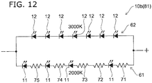
- FIG. 12 is a circuit diagram showing a light-emitting circuit according to the present embodiment.
- the light source portion 10b of a light-emitting device 50b includes the light-emitting circuit 81.
- the light-emitting circuit 81 includes one or more first light-emitting elements 11 disposed in a first region 51, and one or more second light-emitting elements 12 disposed in a second region 52.
- the second region 52 surrounds the first region 51.
- the color temperature of the light emitted from the second light-emitting element 12 is different from the color temperature of the light emitted from the first light-emitting element 11.
- a first circuit 61 that includes the one or more first light-emitting elements 11 and a second circuit 62 that includes the one or more second light-emitting elements 12 are connected in parallel to each other.
- the number of stages of the first light-emitting elements 11 connected in series in the first circuit 61 is less than the number of stages of the second light-emitting elements 12 connected in series in the second circuit 62.
- first light-emitting elements 11 are disposed in the first region 51 positioned at the central vicinity of the wiring substrate 15.
- the first region 51 includes the center of the wiring substrate 15.
- seven second light-emitting elements 12 are arranged in a circular configuration in the second region 52 so as to surround the first region 51.
- the first light-emitting elements 11 and the second light-emitting elements 12 are, for example, LEDs.
- the first light-emitting element 11 emits light having a color temperature of 2000 K (Kelvin).
- the first circuit 61 is configured by connecting the four first light-emitting elements 11 with, for example, five resistance elements 71 to 75 via wiring of the wiring substrate 15, in a series connection.
- the first circuit 61 is configured by connecting the resistance element 71, the first light-emitting element 11, the resistance element 72, the resistance element 73, the first light-emitting element 11, the resistance element 74, the first light-emitting element 11, the resistance element 75, and the first light-emitting element 11, in a series connection in order from the positive side toward the negative side.
- the total number of the first light-emitting elements 11 is 4, and the number of stages of the first light-emitting elements 11 connected in series also is 4.
- the anodes of the first light-emitting elements 11 are connected to the positive side, and the cathodes of the first light-emitting elements 11 are connected to the negative side.
- the second light-emitting element 12 emits light having a color temperature of 3000 K.
- the second circuit 62 is configured by connecting the second light-emitting elements 12 via wiring of the wiring substrate 15 in a series connection.
- the second circuit 62 in the example shown in FIG. 12 for example, seven second light-emitting elements 12 are connected in series from the positive side toward the negative side without being interposed by resistance elements.
- the total number of the second light-emitting elements 12 is 7, and the number of stages of the second light-emitting elements 12 connected in series also is 7.
- the anodes of the second light-emitting elements 12 is connected to the positive side, and the cathodes of the second light-emitting elements 12 is connected to the negative side.
- the positive-side terminal of the first circuit 61 and the positive-side terminal of the second circuit 62 are connected to each other, and the negative-side terminal of the first circuit 61 and the negative-side terminal of the second circuit 62 are connected to each other.
- the first circuit 61 and the second circuit 62 are connected in parallel between the positive-side terminal and the negative-side terminal.
- first light-emitting elements 11 it is sufficient for the first light-emitting elements 11 to be disposed in the first region 51, for the second light-emitting elements 12 to be disposed in the second region 52 surrounding the first region 51. It is also sufficient for the number of stages of the first light-emitting elements 11 connected in series in the first circuit 61 to be less than the number of stages of the second light-emitting elements 12 connected in series in the second circuit 62.
- FIG. 13A is a graph showing the behavior of the first light-emitting element and the second light-emitting element of the present embodiment, in which the horizontal axis represents the input current, and the vertical axis represents the luminous flux.
- FIG. 13B is a graph showing the behavior of the light-emitting device according to the present embodiment, in which the horizontal axis represents the input current, and the vertical axis represents the color temperature.
- the number of stages of the first light-emitting elements 11 connected in series in the first circuit 61 is less than the number of stages of the second light-emitting elements 12 connected in series in the second circuit 62. Therefore, when a direct current applied to the light-emitting circuit 81 is increased continuously from zero, initially, the first light-emitting elements 11 conduct firstly because the voltage applied between the anode-cathode of the first light-emitting elements 11 is higher than the voltage applied between the anode-cathode of the second light-emitting elements 12. Therefore, a current flows in only the first circuit 61, and a current substantially does not flow in the second circuit 62.
- the first light-emitting elements 11 emit light, and light that has a color temperature of 2000 K is emitted.
- the luminous flux of the first light-emitting elements 11 increases as the input current is increased until the input current value reaches a value I 1 at which the current flowing in the first light-emitting elements 11 substantially saturates.
- the direct current applied to the light-emitting circuit 81 is increased, a current starts to flow in the second light-emitting elements 12 as well.
- the second light-emitting elements 12 also emit light thereby.
- the current value at which the second light-emitting elements 12 start to emit light is taken as I 2 .
- the current value is in the range not less than 0 and not more than I 2 , the color temperature of the light is constant at 2000 K, and only the luminous flux changes according to the input current. It is preferable for the current value I 2 to be not more than the current value I 1 .
- the light emitted from the light source portion 10b becomes the mixed light of the light emitted from the first light-emitting elements 11 and the light emitted from the second light-emitting elements 12, and the color temperature has a value between 2000 K and 3000 K. Then, as the input current value is increased until the input current value reaches a value I 3 at which the current flowing in the second light-emitting elements 12 saturates, the luminous flux of the second light-emitting elements 12 increases while the luminous flux of the first light-emitting elements 11 is substantially constant.
- the color temperature of the light emitted from the light source portion 10b also changes because the proportion of the luminous flux of the first light-emitting elements 11 and the luminous flux of the second light-emitting elements 12 changes. Accordingly, when the current value is in the range not less than I 2 and not more than I 3 , as the input current is increased, the luminous flux increases, thus the color temperature of the light increases from 2000 K to converge to a prescribed value between 2000 K and 3000 K.
- the resistance values of the resistance elements 71 to 75 are adjusted so that the anode-cathode voltage of the first light-emitting elements 11 and the anode-cathode voltage of the second light-emitting elements 12 are substantially equal when the current value reaches I 3 .
- the light-emitting device 50b when the first light-emitting element 11 is switched ON, light is emitted from the first region 51, and the light L1 that is condensed by the first light condenser 22 and the light L2 that is condensed by the second light condenser 23 are emitted from the light-emitting device 50b. Light that has a small FWHM can be obtained thereby.
- the second light-emitting element 12 is switched ON, light is emitted from the second region 52, and the light L3 that is diffused by the first light guide portion 24 exits from the light-emitting device 50b. Light that has a large FWHM can be obtained thereby.
- adjusting the input current value can control the color temperature and the light distribution angle of the emitted light by changing the luminous flux of each light-emitting element.
- FIG. 14 is a plan view showing a light source portion of the present embodiment.
- FIG. 15 is a circuit diagram showing a light-emitting circuit according to the present embodiment.
- one or more first light-emitting elements 11 is provided in the first region 51, and one or more first light-emitting elements 11, one or more second light-emitting elements 12, one or more third light-emitting elements 13, and one or more fourth light-emitting elements 14 are provide in the second region 52.
- the first light-emitting elements 11 is provided in both the first region 51 and the second region 52, and the second light-emitting elements 12, the third light-emitting elements 13, and the fourth light-emitting elements 14 are provided in only the second region 52.
- the number of the illustrated light-emitting elements is less than the actual number to simplify the drawing.
- the total number of the first light-emitting elements 11, the total number of the second light-emitting elements 12, the total number of the third light-emitting elements 13, and the total number of the fourth light-emitting elements 14 each are 12.
- the color temperature of the light emitted from the first light-emitting element 11 is 2700 K
- the color temperature of the light emitted from the second light-emitting element 12 is 2000 K
- the color temperature of the light emitted from the third light-emitting element 13 is 3500 K
- the color temperature of the light emitted from the fourth light-emitting element 14 is 6500 K.
- the color temperature of the light emitted from the light-emitting elements is not required to be the example recited above, and it is sufficient for the color temperature of the light emitted from the first light-emitting element 11, the color temperature of the light emitted from the second light-emitting element 12, the color temperature of the light emitted from the third light-emitting element 13, and the color temperature of the light emitted from the fourth light-emitting element 14 to be different from each other.
- a light-emitting circuit 82 is provided in the light source portion 10c.
- the light-emitting circuit 82 includes the first to fourth light-emitting elements described above, multiple first resistance elements 76, and multiple second resistance elements 77.
- the first circuit 61, the second circuit 62, a third circuit 63, and a fourth circuit 64 are provided in the light-emitting circuit 82.
- the first circuit 61 and the second circuit 62 are connected in parallel to each other, and the third circuit 63 and the fourth circuit 64 are connected in parallel to each other.
- the first circuit 61 is, for example, a unit circuit configured by three first light-emitting elements 11 connected in parallel to each other, four unit circuits are provided, and the four unit circuits and the multiple first resistance elements 76 are connected in series. Accordingly, in the first circuit 61, the total number of the first light-emitting elements 11 is 12, and the number of stages of the first light-emitting elements 11 connected in series is 4. The resistance values may be the same or different between the multiple first resistance elements 76.
- the second circuit 62 for example, twelve second light-emitting elements 12 are connected in series without being interposed by resistance elements. Accordingly, in the second circuit 62, the total number of the second light-emitting elements 12 is 12, and the number of stages of the second light-emitting elements 12 connected in series also is 12.
- a unit circuit is configured by three third light-emitting elements 13 connected in parallel to each other, four unit circuits are provided, and the four unit circuits and the multiple second resistance elements 77 are connected in series. Accordingly, in the third circuit 63, the total number of the third light-emitting elements 13 is 12; and the number of stages of the third light-emitting elements 13 connected in series is 4.
- the resistance values may be the same or different between the multiple second resistance elements 77.
- the fourth circuit 64 for example, twelve fourth light-emitting elements 14 are connected in series without being interposed by resistance elements. Accordingly, in the fourth circuit 64, the total number of the fourth light-emitting elements 14 is 12, and the number of stages of the fourth light-emitting elements 14 connected in series is 12.
- the first light-emitting elements 11 are disposed in both the first region 51 and the second region 52, and thus the light that is emitted from the first light-emitting elements 11 exits from the first light condenser 22, the second light condenser 23, and the first light guide portion 24 of the optical member 20.
- the second light-emitting elements 12, the third light-emitting elements 13, and the fourth light-emitting elements 14 are disposed in only the second region 52, and thus the light that is emitted from the second light-emitting elements 12, the third light-emitting elements 13, and the fourth light-emitting elements 14 exits from the first light guide portion 24.
- the first circuit 61 and the second circuit 62 are connected to the same power supply, and have the same voltage applied. Thereby, as described in the first embodiment, when the input current value is increased gradually from zero, the first light-emitting elements 11 start to emit light firstly, and the second light-emitting elements 12 start to emit light about when the current flowing in the first light-emitting elements 11 saturates. As a result, as the input current value is changed, the color temperature, the luminous flux, and the light distribution angle of the entirety change according to a prescribed relationship.
- the third circuit 63 and the fourth circuit 64 are connected to the same power supply, and have the same voltage applied. Thereby, when the input current value is increased gradually from zero, the third light-emitting elements 13 start to emit light firstly; and the fourth light-emitting elements 14 start to emit light about when the current flowing in the third light-emitting elements 13 saturates. As a result, when the input current value is changed, the color temperature and the luminous flux of the entirety change according to a prescribed relationship.
- the ratio of the light emitted from the first light-emitting elements 11, the second light-emitting elements 12, the third light-emitting elements 13, and the fourth light-emitting elements 14 can be controlled by controlling the ratio of the current value flowing in the first circuit 61 and the second circuit 62 and the current value flowing in the third circuit 63 and the fourth circuit 64. By suitably adjusting this control, the color of the light emitted from the light-emitting device 50c can be changed to follow blackbody radiation.
- FIG. 16 is a chromaticity coordinates diagram showing the change of the color of the light emitted from the light-emitting device, in which the horizontal axis represents x, and the vertical axis represents y.
- the curve shown by the broken line is the theoretical curve of the color change of blackbody radiation
- the curve shown by the solid line represents the simulation results of the color change of the light emitted by the light-emitting device according to the present embodiment
- the straight line shown by the single dot-dash line represents the color change of the light emitted by a light-emitting device using only two types of light-emitting elements.
- the light that is emitted from the light-emitting device 2 can be changed to follow blackbody radiation.
- the first circuit 61 that includes the first light-emitting elements 11 and the second circuit 62 that includes the second light-emitting elements 12 are connected in parallel to each other.
- the number of stages of the first light-emitting elements 11 connected in series in the first circuit 61 is less than the number of stages of the second light-emitting elements 12 connected in series in the second circuit 62. Therefore, the state in which the first light-emitting elements 11 emit light solitarily can transition smoothly and continuously to the state in which both the first light-emitting elements 11 and the second light-emitting elements 12 emit light.
- the third circuit 63 that includes the third light-emitting elements 13 and the fourth circuit 64 that includes the fourth light-emitting elements 14 are connected in parallel to each other.
- the number of stages of the third light-emitting elements 13 connected in series in the third circuit 63 is less than the number of stages of the fourth light-emitting elements 14 connected in series in the fourth circuit 64. Therefore, the state in which the third light-emitting elements 13 emit light solitarily can transition smoothly and continuously to the state in which both the third light-emitting elements 13 and the fourth light-emitting elements 14 emit light.
- the state in which the first light-emitting elements 11 emit light solitarily can transition smoothly and continuously to the state in which all of the light-emitting elements emit light by appropriately controlling the current value flowing in the circuit in which the first circuit 61 and the second circuit 62 are connected in parallel and the current value flowing in the circuit in which the third circuit 63 and the fourth circuit 64 are connected in parallel.
- the color temperature, the luminous flux, and the light distribution angle can be changed continuously, so that the user is less likely to feel awkwardness when controlling the light.
- FIG. 17 is a plan view showing a light source portion of the present embodiment.
- the light-emitting circuit according to the present embodiment is similar to the light-emitting circuit 82 shown in FIG. 15.
- both the first light-emitting element 11 and the second light-emitting element 12 are provided in the first region 51.
- the first light-emitting element 11, the second light-emitting element 12, the third light-emitting element 13, and the fourth light-emitting element 14 are provided in the second region 52.
- the number of the illustrated light-emitting elements is less than the actual number to simplify the drawing. This is similar for FIG. 18 and FIG. 19 described below as well.
- the light exited from the first light condenser 22 and the second light condenser 23 to illuminate a narrow-angle region are also illuminate with the state in which the first light-emitting element 11 emits light solitarily can be changed continuously to the state in which both the first light-emitting element 11 and the second light-emitting element 12 emit light.
- the configuration, the operations, and the effects of the present embodiment are similar to those of the fourth embodiment.
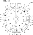
- FIG. 18 is a plan view showing a light source portion of the present embodiment.
- FIG. 19 is an end view showing an optical member of the present embodiment.
- the light source portion 10e is provided in a light-emitting device 50e according to the present embodiment.
- one or more first light-emitting elements 11 is provided in the first region 51.
- One or more first light-emitting elements 11, one or more second light-emitting elements 12, one or more third light-emitting elements 13, and one or more fourth light-emitting elements 14 are provided in the second region 52.
- One or more first light-emitting elements 11, one or more second light-emitting elements 12, one or more third light-emitting elements 13, and one or more fourth light-emitting elements 14 are provided in a third region 53 as well.
- the first region 51 is a region having a circular configuration including the center of the wiring substrate 15
- the second region is a region having a circular annular configuration disposed at the periphery of the first region 51
- the third region 53 is a region having a circular annular configuration disposed at the periphery of the second region 52.
- the color temperature of the light emitted from the first light-emitting element 11 is 2700 K
- the color temperature of the light emitted from the second light-emitting element 12 is 2000 K
- the color temperature of the light emitted from the third light-emitting element 13 is 3500 K
- the color temperature of the light emitted from the fourth light-emitting element 14 is 6500 K.
- this is not requirement, and it is sufficient for the color temperatures to be different from each other.
- the optical member 20a further includes the flat plate portion 27 and the second light guide portion 26 guiding the light incident from the third region 53 at the periphery of the second region 52.
- the FWHM of the light emitted from the second light guide portion 26 is larger than the FWHM of the light emitted from the first light guide portion 24.
- the second light guide portion 26 is provided at the outer side of the flat plate portion 25.
- the second light guide portion 26 is a transparent tubular member surrounding the periphery of the first light guide portion 24 in a ring configuration.
- the second light guide portion 26 is disposed at a position corresponding to the third region 53 of the light source portion 10c and is disposed at, for example, a position opposing the third region 53.
- the color temperature can be controlled in a wide range because four types of light-emitting elements having mutually-different color temperatures are provided.
- the state in which the first light-emitting elements 11 emit light solitarily can transition smoothly and continuously to the state in which all of the light-emitting elements emit light.
- the color temperature, the luminous flux, and the light distribution angle can be changed continuously. Also, it is possible to change the color of the light to follow blackbody radiation.
- Light-emitting elements are disposed in the third region 53 of the light source portion 10e, and the optical member 20a includes the second light guide portion 26 guiding the light incident from the third region 53, thus the light distribution angle can be changed in a wider range.
- the invention can be utilized in, for example, an indoor lighting device, etc.
Landscapes
- Engineering & Computer Science (AREA)
- General Engineering & Computer Science (AREA)
- Physics & Mathematics (AREA)
- Optics & Photonics (AREA)
- Microelectronics & Electronic Packaging (AREA)
- General Physics & Mathematics (AREA)
- Non-Portable Lighting Devices Or Systems Thereof (AREA)
- Planar Illumination Modules (AREA)
Abstract
Description
- Embodiments relate to a light-emitting device, a lighting device and an optical member.
- In recent years, a lighting device that can switch the light distribution angle is desirable. For example, it is desirable for one lighting device to illuminate an entire room by increasing the light distribution angle for one condition, and to illuminate a narrow area by reducing the light distribution angle for another condition. To realize such a lighting device, it may be considered to use mechanical means to change the positional relationship of a light source and an optical system. However, a lighting device in which such mechanical means is provided is undesirably large and expensive, needs time to switch, and has poor interior-stylishness.
- A light-emitting device according to certain embodiment, includes one or more first light-emitting elements, one or more second light-emitting elements, and an optical member including a first light condenser portion, a second light condenser portion, and a first light guide portion. The first light condenser portion is disposed at a position corresponding to the first light-emitting element. The first light condenser portion condenses a portion of light emitted from the first light-emitting element. The second light condenser portion surrounds the first light condenser portion. The second light condenser portion condenses a portion of the light that is not incident to the first light condenser portion among the light emitted from the first light-emitting element. The first light guide portion surrounds the second light condenser portion and at a position corresponding to the second light-emitting element. The first light guide portion guides light emitted from the second light-emitting element by causing total reflection in an interior of the first light guide portion. A full width at half maximum of light exiting from the first light guide portion is larger than a full width at half maximum of light exiting from the first light condenser portion.
- A light-emitting device according to certain embodiment, includes an optical member including a first light condenser portion, a second light condenser portion, a first light guide portion, one or more first light-emitting elements, and one or more second light-emitting elements. The first light condenser portion has a convex lens. The second light condenser portion surrounds the first light condenser portion. The second light condenser portion has an inner surface and an outer surface being curved outward as approaching a light exiting surface, while being disposed at a periphery of the first light condenser portion. The first light guide portion has a tubular configuration surrounding a periphery of the second light condenser portion in an annular configuration. The one or more first light-emitting elements are disposed at a position corresponding to the first light condenser portion. The one or more second light-emitting elements are disposed at a position corresponding to the first light guide portion.
- An optical member according to certain embodiment, includes a first light condenser portion condensing light incident on a first light incident region, a second light condenser portion surrounding the first light condenser portion, and a first light guide portion surrounding the second light condenser portion. The second light condenser portion condenses a portion of the light that is not incident to the first light condenser portion and outputs from a position facing the first light incident region The first light guide portion guides light emitted from the second light-emitting element by causing total reflection in an interior of the first light guide portion. A full width at half maximum of light exiting from the first light guide portion is larger than a full width at half maximum of light exiting from the first light condenser portion.
- An optical member according to certain embodiment, includes a first light condenser portion, a second light condenser portion having an inner surface and an outer surface being curved outward as approaching a light exiting surface, the second light condenser portion surrounding the first light condenser portion; and a first light guide portion having a tubular configuration surrounding a periphery of the second light condenser portion in an annular configuration.
- A light-emitting circuit according to certain embodiment, includes one or more first light-emitting elements disposed in a first region, and one or more second light-emitting elements surrounding the first region. A color temperature of light emitted from the second light-emitting element is different from a color temperature of light emitted from the first light-emitting element. A first circuit and a second circuit are connected in parallel to each other. The first circuit includes the one or more first light-emitting elements. The second circuit includes the one or more second light-emitting elements. A number of stages of the first light-emitting elements connected in series in the first circuit is less than a number of stages of the second light-emitting elements connected in series in the second circuit.
-
-
FIG. 1 is an exploded perspective end view showing a lighting device according to a first embodiment; -
FIG. 2A is an end view showing the lighting device according to the first embodiment; -
FIG. 2B is a perspective view showing the lighting device according to the first embodiment; -
FIG. 3 is a plan view showing a light source portion; -
FIG. 4A is a perspective end view showing an optical member according to the first embodiment; -
FIG. 4B is an end view showing the optical member according to the first embodiment; -
FIG. 5A is a plan view of the optical member according to the first embodiment when viewed from the light incident direction; -
FIG. 5B is a plan view of the optical member according to the first embodiment when viewed from the light exiting direction; -
FIG. 5C is a perspective view showing the optical member according to the first embodiment; -
FIG. 6 shows simulation results of the path of the light emitted from a first light-emitting element; -
FIG. 7 shows simulation results of the path of the light emitted from a second light-emitting element; -
FIG. 8 is an end view showing a positional relationship between a cover member and the path of the light emitted from a diffuser plate; -
FIG. 9 shows a light-emitting device according to a second embodiment; -
FIG. 10A shows dimensions of a first light guide portion and a second light guide portion of an example; -
FIG. 10B is a graph showing simulation results of the distribution of the light emitted from the first light guide portion of the example, in which the horizontal axis represents the angle from the center, and the vertical axis represents the luminous intensity; -
FIG. 10C is a graph showing simulation results of the distribution of the light emitted from the second light guide portion of the example, in which the horizontal axis represents the angle from the center, and the vertical axis represents the luminous intensity; -
FIG. 11 is a plan view showing a light source portion of a third embodiment; -
FIG. 12 is a circuit diagram showing a light-emitting circuit according to the third embodiment; -
FIG. 13A is a graph showing the behavior of a first light-emitting element and a second light-emitting element of the third embodiment, in which the horizontal axis represents the input current, and the vertical axis represents the luminous flux; -
FIG. 13B is a graph showing the behavior of a light-emitting device according to the third embodiment, in which the horizontal axis represents the input current, and the vertical axis represents the color temperature; -
FIG. 14 is a plan view showing a light source portion of a fourth embodiment; -
FIG. 15 is a circuit diagram showing a light-emitting circuit according to the fourth embodiment; -
FIG. 16 is a chromaticity coordinates diagram showing the change of the color of the light emitted from a light-emitting device, in which the horizontal axis represents x, and the vertical axis represents y; -
FIG. 17 is a plan view showing a light source portion of a fifth embodiment; -
FIG. 18 is a plan view showing a light source portion of a sixth embodiment; and -
FIG. 19 is an end view showing an optical member of the sixth embodiment. - First, a first embodiment will be described.
-
FIG. 1 is an exploded perspective end view showing a lighting device according to an embodiment. -
FIG. 2A is an end view showing the lighting device according to the present embodiment. -
FIG. 2B is a perspective view showing the lighting device according to the present embodiment. - First, the configuration of the
lighting device 1 according to the present embodiment will be summarily described. Thelighting device 1 includes alight source portion 10, anoptical member 20, adiffuser plate 30, and acover member 40. A light-emittingdevice 50 includes thelight source portion 10 and theoptical member 20. - The
light source portion 10 includes one or more first light-emittingelements 11 and one or more second light-emittingelements 12. Theoptical member 20 includes afirst light condenser 22, a secondlight condenser 23, and a firstlight guide portion 24. Thefirst light condenser 22 is disposed at a position corresponding to the first light-emittingelement 11, and condenses the light incident from the first light-emittingelement 11. The secondlight condenser 23 surrounds thefirst light condenser 22, and condenses light emitted from the first light-emittingelement 11 and not incident on thefirst light condenser 22. The firstlight guide portion 24 is disposed at a position corresponding to the second light-emittingelement 12 while surrounding the secondlight condenser 23, and guides the light incident from the second light-emittingelement 12 by causing total reflection in the interior of the firstlight guide portion 24. The full width at half maximum (hereinafter referred to as "FWHM") of the light emitted from the firstlight guide portion 24 is larger than the FWHM of the light emitted from thefirst light condenser 22. - The
diffuser plate 30 is positioned such that the light having been emitted from thelight source portion 10 and having passed through theoptical member 20 is incident. Thecover member 40 is disposed at a position covering the lateral surfaces of the light-emittingdevice 50 and thediffuser plate 30. Thecover member 40 has a substantially tubular configuration, and reflects a portion of the light having passed through thediffuser plate 30 at the inner surface of thecover member 40. - Details will now be described.
-
FIG. 3 is a plan view showing thelight source portion 10. - One
wiring substrate 15 is provided in thelight source portion 10. Although an example is illustrated in which thewiring substrate 15 has substantially a disk configuration, this is not requirement. In thewiring substrate 15, for example, wiring is provided inside a base material formed using a resin material. The first light-emittingelement 11 and the second light-emittingelement 12 are mounted on a mountingsurface 15a of thewiring substrate 15. - For example, four first light-emitting
elements 11 are disposed at the central vicinity of thewiring substrate 15. For example, thirteen second light-emittingelements 12 are arranged in a region surrounding the four first light-emittingelements 11 to have a circular configuration. In the present embodiment, although an example is shown in which the number of the first light-emittingelements 11 is 4 and the number of the second light-emittingelements 12 is 13, this is not requirement. There is no requirement for the numbers as long as the first light-emittingelements 11 are disposed at the central vicinity of thewiring substrate 15, and the second light-emittingelements 12 are arranged to surround the first light-emittingelements 11. The first light-emittingelement 11 and the second light-emittingelement 12 are, for example, Light-Emitting Diodes (LEDs). The first light-emittingelement 11 and the second light-emittingelement 12 can be switched ON independently from each other. -
FIG. 4A is a perspective end view showing theoptical member 20 according to the present embodiment. -
FIG. 4B is an end view showing theoptical member 20 according to the present embodiment. -
FIG. 5A is a plan view of theoptical member 20 according to the present embodiment when viewed from the light incident direction. -
FIG. 5B is a plan view of theoptical member 20 according to the present embodiment when viewed from the light exiting direction. -
FIG. 5C is a perspective view showing theoptical member 20 according to the present embodiment. - The
optical member 20 is a transparent member formed as one body of a transparent material. The configuration of theoptical member 20 is substantially a rotated body having a central axis C as a rotation axis, and has light incident surfaces 21 and a light-exitingsurface 29. The light incident surfaces 21 face thelight source portion 10. As described below, the light incident surfaces 21 of theoptical member 20 forms projections and depressions to configure uneven surface as the entire light incident surfaces. This surface unevenness can realize an optical function. The light-exitingsurface 29 is a plane substantially orthogonal to the central axis C. Hereinbelow, among the directions in which the central axis C of theoptical member 20 extends, the direction from the light-exitingsurface 29 toward the light incident surfaces 21 is called the "light incident direction"; and the direction from the light incident surfaces 21 toward the light-exitingsurface 29 is called the "light exiting direction". - The
first light condenser 22 that protrudes in the light incident direction is provided at the central portion of entire of the light incident surfaces 21. Thefirst light condenser 22 is disposed at a position corresponding to the first light-emittingelement 11 of thelight source portion 10, and is disposed at, for example, a position facing the first light-emittingelement 11. Thefirst light condenser 22 has a convex lens configuration and is, for example, a portion of a rotated ellipsoid. Anouter surface 22a of thefirst light condenser 22 is a convex curved surface. The minimum curvature radius of theouter surface 22a is not less than 0.3 mm and not more than 13 mm. For example, the minimum curvature radius of theouter surface 22a can be measured in a cross section including the central axis C. - The second
light condenser 23 is provided so as to surround thefirst light condenser 22. The secondlight condenser 23 has a substantially truncated circular conical configuration having a flattened peak. The secondlight condenser 23 faces a region of thelight source portion 10 between the first light-emittingelement 11 and the second light-emittingelement 12. The surface of the secondlight condenser 23 includes aninner surface 23a, anupper surface 23b, and anouter surface 23c. - The
inner surface 23a contacts theouter surface 22a of thefirst light condenser 22, and is inclined away from the central axis C as approaching in the light incident direction. Theupper surface 23b is positioned at the periphery of theinner surface 23a, and contacts theinner surface 23a. Theupper surface 23b is a plane having a circular annular configuration parallel to the light-exitingsurface 29. Theouter surface 23c is positioned at the periphery of theupper surface 23b, and contacts theupper surface 23b. Theouter surface 23c is inclined away from the central axis C as approaching in the light exiting direction. Theouter surface 23c is curved outward with respect to the light-exitingsurface 29, that is, convex toward the light incident direction. The minimum curvature radius of theouter surface 23c is not less than 0.6 mm and not more than 28 mm. The minimum curvature radius of theouter surface 23c also can be measured at, for example, a cross section including the central axis C. - The first
light guide portion 24 is provided to surround the secondlight condenser 23. The firstlight guide portion 24 has a tubular configuration surrounding the periphery of the secondlight condenser 23 in an annular configuration. The cross-sectional configuration of the firstlight guide portion 24 is a trapezoid in a plane perpendicular to the light-exitingsurface 29, for example, a plane elongated in the central axis C. The surface of the firstlight guide portion 24 includes aninner surface 24a, anupper surface 24b, and anouter surface 24c. - The
inner surface 24a contacts theouter surface 23c of the secondlight condenser 23, and is inclined away from the central axis C as approaching in the light incident direction. Aboundary line 28a between theouter surface 23c of the secondlight condenser 23 and theinner surface 24a of the firstlight guide portion 24 is positioned further in the light exiting direction than aboundary line 28b between theouter surface 22a of thefirst light condenser 22 and theinner surface 23a of the secondlight condenser 23. In other words, the distance between theboundary line 28a and the light-exitingsurface 29 is shorter than the distance between theboundary line 28b and the light-exitingsurface 29. - The
upper surface 24b is disposed at the periphery of theinner surface 24a and contacts theinner surface 24a. Theupper surface 24b is a plane having a circular ring configuration parallel to the light-exitingsurface 29. Theupper surface 24b is positioned so as to correspond to the second light-emittingelement 12 of thelight source portion 10, and, for example, so as to face the second light-emittingelement 12. Theupper surface 23b of the secondlight condenser 23 and theupper surface 24b of the firstlight guide portion 24 are positioned in the same plane. Theouter surface 24c may be perpendicular to the light-exitingsurface 29, or may be inclined away from the central axis C as approaching in the light exiting direction. - A
flat plate portion 25 is provided at the periphery of the firstlight guide portion 24. It is sufficient for the configuration of theflat plate portion 25 to surround the periphery of the firstlight guide portion 24. It is preferable for theflat plate portion 25 to have a circular annular plate configuration. Anupper surface 25a of theflat plate portion 25 is parallel to the light-exitingsurface 29 of theoptical member 20, and is a plane substantially orthogonal to the central axis C. - The light incident surfaces 21 is positioned and angled so as to be viewed directly from the light exiting direction. In other words, all of the
outer surface 22a of thefirst light condenser 22, theinner surface 23a, theupper surface 23b, theouter surface 23c of the secondlight condenser 23, theinner surface 24a, theupper surface 24b, theouter surface 24c of the firstlight guide portion 24, and theupper surface 25a of theflat plate portion 25 all face the light-exitingsurface 29. Therefore, theoptical member 20 can be made by injection molding, etc. For example, theoptical member 20 can be molded by pouring a transparent resin into a mold opening on the light-exitingsurface 29 side, curing the transparent resin, and withdrawing the transparent resin in the light exiting direction. - The
diffuser plate 30 is formed using a transparent material, for example, glass or a resin material, and diffuses and transmits the incident light. For example, a fine unevenness may be formed in one or both surfaces of thediffuser plate 30. Alternatively, in thediffuser plate 30, a material that has a different refractive index from the base material may be dispersed in the base material. It is sufficient for the configuration of thediffuser plate 30 to cover the light-exitingsurface 29. Thediffuser plate 30 preferably has a disk configuration. Thediffuser plate 30 is disposed at the light-exitingsurface 29 side of theoptical member 20, and contacts, for example, the light-exitingsurface 29. - The
cover member 40 includes aflange 41, ahousing 42, and acone 43. Thecover member 40 is formed of an opaque material, for example, a white resin material, a dark-colored resin material, or a metal material. The configuration of thecover member 40 is substantially a rotated body. The central axis of thecover member 40 substantially matches the central axis C of theoptical member 20. - For example, the
flange 41 has a circular annular plate configuration. Theflange 41 is a portion for fixing thelighting device 1 to a member subject to be fixed, for example, aceiling 100 of a room. Thehousing 42 has a cylindrical configuration in which the entire upper surface and the central portion of the bottom surface are open. The housing42 houses thelight source portion 10, theoptical member 20, and thediffuser plate 30 are placed in the interior of thehousing 42. The outer perimeter portion of thediffuser plate 30 is interposed and fixed between theflat plate portion 25 of theoptical member 20 and the bottom surface of thehousing 42 of thecover member 40. Thecone 43 has a truncated circular conical configuration having a diameter increasing as the distance from thehousing 42 increases. The upper surface and the bottom surface of thecone 43 are open. The interior of thecone 43 communicates with the interior of thehousing 42. When thecover member 40 is formed using a white material, the inner surface of thecone 43 diffusely reflects the light. When thecover member 40 is formed using a dark-colored material, the inner surface of thecone 43 absorbs the light. - Operations of the
lighting device 1 according to the present embodiment will now be described. -
FIG. 6 shows simulation results of the path of the light emitted from the first light-emitting element. -
FIG. 7 shows simulation results of the path of the light emitted from the second light-emitting element. -
FIG. 8 is an end view showing the positional relationship between the cover member and the path of the light exited from the diffuser plate. - When the first light-emitting
element 11 is switched ON, a portion of the light emitted from the first light-emittingelement 11 is incident on theouter surface 22a of thefirst light condenser 22 of theoptical member 20. Theouter surface 22a is a first light incident region where the light is incident on thefirst light condenser 22. Hereinbelow, the light that is incident on thefirst light condenser 22 is called "light L1". The light L1 is condensed by thefirst light condenser 22 having the convex lens configuration, and exits from the light-exitingsurface 29. A FWHM θHW1 of the light L1 exiting from thefirst light condenser 22 is, for example, 24°. - The remainder of the light emitted from the first light-emitting
element 11, that is, the light that is emitted from the first light-emittingelement 11 but is not incident on thefirst light condenser 22 is incident on theinner surface 23a of the secondlight condenser 23. Hereinbelow, the light that is incident on the secondlight condenser 23 is called "light L2." The light L2 passes through the secondlight condenser 23. At least a portion of the light L2 undergoes total reflection at theouter surface 23c, and exits from the light-exitingsurface 29. Theouter surface 23c is curved outward as approaching the light-exitingsurface 29, the light L2 is condensed by undergoing total reflection at theouter surface 23c. - When the second light-emitting
element 12 is switched ON, the greater part of the light emitted from the second light-emittingelement 12 is incident on theupper surface 24b of the firstlight guide portion 24 of theoptical member 20. Theupper surface 24b is a second light incident region where the light is incident on the firstlight guide portion 24. Hereinbelow, the light that is incident on the firstlight guide portion 24 is called "light L3." At least a portion of the light L3 repeats total reflection at theinner surface 24a and theouter surface 24c of the firstlight guide portion 24, is guided through the interior of the firstlight guide portion 24 while diffusing, and thereafter exits from the light-exitingsurface 29. A FWHM θHW2 of the light L3 exiting from the firstlight guide portion 24 is, for example, 68°. The FWHM θHW2 of the light L3 exiting from the firstlight guide portion 24 of theoptical member 20 is larger than the FWHM θHW1 of the light L1 exiting from thefirst light condenser 22. In other words, θ HW2 > θ HW1 . - Thus, when the first light-emitting
element 11 is switched ON in thelighting device 1, the light L1 that is condensed by thefirst light condenser 22 and the light L2 that is condensed by the secondlight condenser 23 exit from thelighting device 1. Light that has a small FWHM can be obtained thereby. On the other hand, when the second light-emittingelement 12 is switched ON, the light L3 that is diffused by the firstlight guide portion 24 exits from thelighting device 1. Light that has a large FWHM can be obtained thereby. Thus, thelighting device 1 can change the light distribution angle of the exiting light by switching between the light-emitting elements that are switched ON. Accordingly, thelighting device 1 can change the illumination area. - The light exiting from the light-exiting
surface 29 of theoptical member 20 is scattered when passing through thediffuser plate 30. Accordingly, the user is less likely to see the "grainy appearance" of the first light-emittingelement 11 or the second light-emitting element 12by seeing through thediffuser plate 30. Also, this can reduce the "uneven color" and the "glare" attributed to the angle of exiting light. Then, the light exiting from thediffuser plate 30 is incident on thecone 43 of thecover member 40. A portion of the light exiting from thediffuser plate 30 reaches the inner surface of thecone 43. In particular, the light traveling at an angle of 30° or less with respect to the mountingsurface 15a of thewiring substrate 15 always reaches the inner surface of thecone 43. Light L4 shows the path of the light exiting from the end of the portion of thediffuser plate 30 exposed inside thecone 43. The Light L4 extends at an angle of 30° with respect to the mountingsurface 15a, and passes through the central axis of thecone 43. Thecone 43 is designed so that the light L4 is incident on the inner surface of thecone 43. When the inner surface of thecone 43 is formed using a white material, the light that reaches the inner surface of thecone 43 is diffusely reflected by the inner surface of thecone 43 and exits outside thelighting device 1. When the inner surface of thecone 43 is formed using a dark-colored material, the light that reaches the inner surface of thecone 43 is absorbed by the inner surface of thecone 43. Another portion of the light exiting from thediffuser plate 30 does not reach the inner surface of thecone 43 and exits directly outside thelighting device 1. - Effects of the present embodiment will now be described.
- In the
lighting device 1, the light distribution angle can be switched by electrical means without providing mechanical means. This can achieve reducing the size and the cost of manufacturing thelighting device 1. Because there is no mechanical operation, it can be realized to obtain the lighting device with extremely short switching time, no noise generation, and high reliability. The external appearance of thelighting device 1 does not suggest that switching of the light distribution angle is possible. Therefore, when thelighting deice 1 is mounted to theceiling 100 of a room and used as a downlight, etc., the interior-stylishness can be improved. - The
lighting device 1 can realize even further cost reduction as a lighting device because both the narrow-angle illumination and the wide-angle illumination can be performed using oneoptical member 20. As described above, the cost can further be reduced by forming theoptical member 20 using injection molding technique, etc. Also, the use is less likely to notice discontinuity when switching the narrow-angle illumination from/to the wide-angle illumination because the position and the surface area of the light-emitting region substantially does not change between the narrow-angle illumination and the wide-angle illumination. - In the
lighting device 1, a portion of the light that exits from thediffuser plate 30 and travels at an angle of 30° or less with respect to the mountingsurface 15a of thewiring substrate 15 does not directly exit outside thelighting device 1 from thediffuser plate 30 because the light is diffusely reflected by the inner surface of thecone 43 when thecover member 40 is formed using a white material, or absorbed by the inner surface of thecone 43 when thecover member 40 is formed using a dark-colored material. Thereby, the light that is emitted from the first light-emittingelements 11 and the second light-emittingelements 12 at a shallow angle is less likely to directly enter the eyes of the user, and glare can be alleviated. Also, in thelighting device 1, the light exiting surface area can be reduced because the light L1 and L2 for narrow-angle illumination and the light L3 for wide-angle illumination can exit from oneoptical member 20. This can lower the height of thecone 43 while shielding the light at 30° or less, thus theentire lighting device 1 can be compact. - The first light-emitting
elements 11 and the second light-emittingelements 12 may be switched ON simultaneously. Thereby, for example, a work space such as a desk, etc., can be illuminated to be brighter by the first light-emittingelements 11 while illuminating the entire room by the second light-emittingelements 12. In such a case, the color temperature of the light emitted by the first light-emittingelements 11 and the color temperature of the light emitted by the second light-emittingelements 12 may be different from each other. For example, the desk may be illuminated using white light by setting at 6500 K (Kelvin) as the color temperature of the light emitted from the first light-emittingelements 11 while illuminating the entire room with warm white light by setting at 2700 K as the color temperature of the light emitted from the second light-emittingelements 12. - The narrow-angle illumination and the wide-angle illumination may be switched by using a human detecting sensor. For example, the entire room may be illuminated by switching ON only the second light-emitting
elements 12 when a human is not at the vicinity of a work space such as a desk, etc., or the work space may be illuminated by switching ON both the first light-emittingelements 11 and the second light-emittingelements 12 when the human is in the work space. Alternatively, for example, both the first light-emittingelements 11 and the second light-emittingelements 12 may be switched OFF when the room is vacant. Only the first light-emittingelements 11 may be switched ON to locally illuminate only the entrance vicinity when a human appears at the entrance of the room. When the human enters the room, the entire room may be brightly illuminated by switching ON both the first light-emittingelements 11 and the second light-emittingelements 12. - A second embodiment will now be described.
-
FIG. 9 shows a light-emitting device according to the present embodiment. - As a general rule in the following description, only the differences with the first present embodiment are described. Other than the following description, the present embodiment is similar to the first embodiment. This is similar for the other embodiments described below as well.
- In addition to the configuration of the light-emitting
device 50 according to the first embodiment, one or more third light-emittingelements 13 are provided in alight source portion 10a in the light-emittingdevice 50a according to the present embodiment, and a secondlight guide portion 26 and aflat plate portion 27 are provided in anoptical member 20a. - For example, multiple third light-emitting
elements 13 are arranged in a circular configuration in a region surrounding the region where the second light-emittingelements 12 are arranged on the mountingsurface 15a of thewiring substrate 15. The third light-emittingelement 13 is, for example, an LED. The third light-emittingelement 13 can be switched ON independently from the first light-emittingelement 11 and the second light-emittingelement 12. - The second
light guide portion 26 is provided at the outer side of theflat plate portion 25. The secondlight guide portion 26 is a transparent tubular member surrounding the periphery of the firstlight guide portion 24 in an annular configuration. The secondlight guide portion 26 is disposed at a position corresponding to the third light-emittingelement 13, and is disposed at a position facing, for example, the third light-emittingelement 13. - The surface of the second
light guide portion 26 includes aninner surface 26a, anupper surface 26b, and anouter surface 26c. Theinner surface 26a contacts theupper surface 25a of theflat plate portion 25. Theinner surface 26a is, for example, parallel to the central axis C. Theupper surface 26b is disposed at the periphery of theinner surface 26a, and contacts theinner surface 26a. Theupper surface 26b is a plane having a circular annular configuration parallel to the light-exitingsurface 29 and faces the third light-emittingelement 13. Theupper surface 26b is positioned in the same plane as theupper surface 23b of the secondlight condenser 23 and theupper surface 24b of the firstlight guide portion 24. Theouter surface 26c contacts theupper surface 26b. Theouter surface 26c is, for example, parallel to the central axis C. The cross-sectional configuration of the secondlight guide portion 26 is a rectangle in a plane perpendicular to the light-exitingsurface 29, for example, a plane including the central axis C. Other than a rectangle, the cross-sectional configuration of the secondlight guide portion 26 may be a trapezoid. - The taper angles, in other words, the angles with respect to the central axis C, of the
inner surface 26a and theouter surface 26c of the secondlight guide portion 26 are smaller than the taper angles of theinner surface 24a and theouter surface 24c of the firstlight guide portion 24. Accordingly, the taper ratio of the secondlight guide portion 26 is smaller than the taper ratio of the firstlight guide portion 24. The "taper ratio" of the light guide portion is the value defined as (Wout - Win)/H, wherein the width of the end surface of the light guide portion on the light incident surfaces 21 side is taken as Win, the width of the end surface of the light guide portion on the light-exitingsurface 29 side is taken as Wout, and the length along the central axis C of the light guide portion is taken as H. The end surface of the firstlight guide portion 24 on the light incident surfaces 21 side is theupper surface 24b. The end surface of the firstlight guide portion 24 on the light-exitingsurface 29 side is a plane connecting theboundary line 28a and theupper surface 25a of theflat plate portion 25. The end surface of the secondlight guide portion 26 on the light incident surfaces 21 side is theupper surface 26b. The end surface of the secondlight guide portion 26 on the light-exitingsurface 29 side is a plane connecting theupper surface 25a of theflat plate portion 25 and anupper surface 27a of theflat plate portion 27. The taper ratio of the firstlight guide portion 24 is, for example, greater than 0 and not more than 0.54. The taper ratio of the secondlight guide portion 26 is, for example, not less than 0 and not more than 0.1. Thereby, the FWHM of the light exiting from the secondlight guide portion 26 is larger than the FWHM of the light exiting from the firstlight guide portion 24. - The
flat plate portion 27 is provided at the outer side of the secondlight guide portion 26. Theupper surface 27a of theflat plate portion 27 is a plane having a circular annular configuration parallel to the light-exitingsurface 29. The thickness of theflat plate portion 27 is, for example, substantially the same as the thickness of theflat plate portion 25. Theoptical member 20a that includes the secondlight guide portion 26 and theflat plate portion 27 is formed as one body of a transparent material. - Operations of the lighting device according to the present embodiment will now be described.
- When the third light-emitting
element 13 is switched ON, the greater part of the light emitted from the third light-emittingelement 13 is incident on theupper surface 26b of the secondlight guide portion 26. Theupper surface 26b is a third light incident region where the light is incident on the secondlight guide portion 26. At least a portion of the light incident on the secondlight guide portion 26 at theupper surface 26b repeats total reflection at theinner surface 26a and theouter surface 26c, propagates through the secondlight guide portion 26, and exits from the light-exitingsurface 29. A FWHM θHW3 of the light exiting from the secondlight guide portion 26 is larger than the FWHM θHW2 of the light exiting from the firstlight guide portion 24. In other words, θ HW3 > θ HW2 > θ HW1. - Effects of the present embodiment will now be described.
- According to the present embodiment, light obtained by switching ON the third light-emitting
element 13 can have a larger FWHM than those when switching ON the first light-emittingelement 11 or the second light-emittingelement 12. Thereby, the light distribution angle can be switched in three levels. - A lighting device according to an example will now be described.
-
FIG. 10A shows dimensions of the firstlight guide portion 24 and the secondlight guide portion 26 of the example. -
FIG. 10B is a graph showing simulation results of the distribution of the light exiting from the firstlight guide portion 24 of the example, in which the horizontal axis is the angle from the center, and the vertical axis is the luminous intensity. -
FIG. 10C is a graph showing simulation results of the distribution of the light emitted from the secondlight guide portion 26 of the example, in which the horizontal axis represents the angle from the center, and the vertical axis represents the luminous intensity. - For example, the FWHM θHW2 is 68° when the width Win of the end portion of the first
light guide portion 24 on the side from which light is incident is set to 3 mm, the width Wout of the end portion of the firstlight guide portion 24 on the side from which light exits is set to 6 mm, and the length H extending in the light exiting direction of the firstlight guide portion 24 is set to 10.9 mm. On the other hand, the FWHM θHW3 is 112° when the width Win of the end portion of the secondlight guide portion 26 on the side from which the light is incident is set to 3 mm, the width Wout of the end portion of the secondlight guide portion 26 on the side from which light exits is set to 3 mm, and the length H extending in the light exiting direction of the secondlight guide portion 26 is set to 10.9 mm. As described above, the FWHM θHW1 of the light L1 exiting from thefirst light condenser 22 is, for example, 24°. These values are shown collectively in Table 1 recited below.[Table 1] light-emitting element first light-emitting element 11second light-emitting element 12third light-emitting element 13transmitting portion first light condenser 22first light guide portion 24second light guide portion 26FWHM [°] 24 68 112 - A third embodiment will now be described.
-
FIG. 11 is a plan view showing a light source portion of the present embodiment. -
FIG. 12 is a circuit diagram showing a light-emitting circuit according to the present embodiment. - The
light source portion 10b of a light-emittingdevice 50b according to the present embodiment includes the light-emittingcircuit 81. The light-emittingcircuit 81 includes one or more first light-emittingelements 11 disposed in afirst region 51, and one or more second light-emittingelements 12 disposed in asecond region 52. Thesecond region 52 surrounds thefirst region 51. The color temperature of the light emitted from the second light-emittingelement 12 is different from the color temperature of the light emitted from the first light-emittingelement 11. In the light-emittingcircuit 81, afirst circuit 61 that includes the one or more first light-emittingelements 11 and asecond circuit 62 that includes the one or more second light-emittingelements 12 are connected in parallel to each other. The number of stages of the first light-emittingelements 11 connected in series in thefirst circuit 61 is less than the number of stages of the second light-emittingelements 12 connected in series in thesecond circuit 62. - For example, four first light-emitting
elements 11 are disposed in thefirst region 51 positioned at the central vicinity of thewiring substrate 15. For example, thefirst region 51 includes the center of thewiring substrate 15. For example, seven second light-emittingelements 12 are arranged in a circular configuration in thesecond region 52 so as to surround thefirst region 51. The first light-emittingelements 11 and the second light-emittingelements 12 are, for example, LEDs. - For example, the first light-emitting
element 11 emits light having a color temperature of 2000 K (Kelvin). For example, thefirst circuit 61 is configured by connecting the four first light-emittingelements 11 with, for example, fiveresistance elements 71 to 75 via wiring of thewiring substrate 15, in a series connection. In the example shown inFIG. 12 , thefirst circuit 61 is configured by connecting theresistance element 71, the first light-emittingelement 11, theresistance element 72, theresistance element 73, the first light-emittingelement 11, theresistance element 74, the first light-emittingelement 11, theresistance element 75, and the first light-emittingelement 11, in a series connection in order from the positive side toward the negative side. In other words, in thefirst circuit 61, the total number of the first light-emittingelements 11 is 4, and the number of stages of the first light-emittingelements 11 connected in series also is 4. The anodes of the first light-emittingelements 11 are connected to the positive side, and the cathodes of the first light-emittingelements 11 are connected to the negative side. - For example, the second light-emitting
element 12 emits light having a color temperature of 3000 K. Thesecond circuit 62 is configured by connecting the second light-emittingelements 12 via wiring of thewiring substrate 15 in a series connection. In thesecond circuit 62 in the example shown inFIG. 12 , for example, seven second light-emittingelements 12 are connected in series from the positive side toward the negative side without being interposed by resistance elements. In other words, in thesecond circuit 62, the total number of the second light-emittingelements 12 is 7, and the number of stages of the second light-emittingelements 12 connected in series also is 7. The anodes of the second light-emittingelements 12 is connected to the positive side, and the cathodes of the second light-emittingelements 12 is connected to the negative side. - In the light-emitting
circuit 81, the positive-side terminal of thefirst circuit 61 and the positive-side terminal of thesecond circuit 62 are connected to each other, and the negative-side terminal of thefirst circuit 61 and the negative-side terminal of thesecond circuit 62 are connected to each other. Thereby, thefirst circuit 61 and thesecond circuit 62 are connected in parallel between the positive-side terminal and the negative-side terminal. Although an example is shown inFIG. 11 andFIG. 12 in which the number of the first light-emittingelements 11 is 4 and the number of the second light-emittingelements 12 is 7, this is not requirement. It is sufficient for the first light-emittingelements 11 to be disposed in thefirst region 51, for the second light-emittingelements 12 to be disposed in thesecond region 52 surrounding thefirst region 51. It is also sufficient for the number of stages of the first light-emittingelements 11 connected in series in thefirst circuit 61 to be less than the number of stages of the second light-emittingelements 12 connected in series in thesecond circuit 62. - Operations of the lighting device according to the present embodiment will now be described.
- First, the operation of the light-emitting
circuit 81 will be described. -
FIG. 13A is a graph showing the behavior of the first light-emitting element and the second light-emitting element of the present embodiment, in which the horizontal axis represents the input current, and the vertical axis represents the luminous flux. -
FIG. 13B is a graph showing the behavior of the light-emitting device according to the present embodiment, in which the horizontal axis represents the input current, and the vertical axis represents the color temperature. - In the light-emitting
circuit 81 as described above, the number of stages of the first light-emittingelements 11 connected in series in thefirst circuit 61 is less than the number of stages of the second light-emittingelements 12 connected in series in thesecond circuit 62. Therefore, when a direct current applied to the light-emittingcircuit 81 is increased continuously from zero, initially, the first light-emittingelements 11 conduct firstly because the voltage applied between the anode-cathode of the first light-emittingelements 11 is higher than the voltage applied between the anode-cathode of the second light-emittingelements 12. Therefore, a current flows in only thefirst circuit 61, and a current substantially does not flow in thesecond circuit 62. Accordingly, only the first light-emittingelements 11 emit light, and light that has a color temperature of 2000 K is emitted. The luminous flux of the first light-emittingelements 11 increases as the input current is increased until the input current value reaches a value I1 at which the current flowing in the first light-emittingelements 11 substantially saturates. - As the direct current applied to the light-emitting
circuit 81 is increased, a current starts to flow in the second light-emittingelements 12 as well. The second light-emittingelements 12 also emit light thereby. The current value at which the second light-emittingelements 12 start to emit light is taken as I2 . When the current value is in the range not less than 0 and not more than I2 , the color temperature of the light is constant at 2000 K, and only the luminous flux changes according to the input current. It is preferable for the current value I2 to be not more than the current value I1. When the current value reaches or exceeds I2, the light emitted from thelight source portion 10b becomes the mixed light of the light emitted from the first light-emittingelements 11 and the light emitted from the second light-emittingelements 12, and the color temperature has a value between 2000 K and 3000 K. Then, as the input current value is increased until the input current value reaches a value I3 at which the current flowing in the second light-emittingelements 12 saturates, the luminous flux of the second light-emittingelements 12 increases while the luminous flux of the first light-emittingelements 11 is substantially constant. The color temperature of the light emitted from thelight source portion 10b also changes because the proportion of the luminous flux of the first light-emittingelements 11 and the luminous flux of the second light-emittingelements 12 changes. Accordingly, when the current value is in the range not less than I2 and not more than I3 , as the input current is increased, the luminous flux increases, thus the color temperature of the light increases from 2000 K to converge to a prescribed value between 2000 K and 3000 K. The resistance values of theresistance elements 71 to 75 are adjusted so that the anode-cathode voltage of the first light-emittingelements 11 and the anode-cathode voltage of the second light-emittingelements 12 are substantially equal when the current value reaches I3 . - Thus, in the light-emitting
device 50b according to the present embodiment, when the first light-emittingelement 11 is switched ON, light is emitted from thefirst region 51, and the light L1 that is condensed by thefirst light condenser 22 and the light L2 that is condensed by the secondlight condenser 23 are emitted from the light-emittingdevice 50b. Light that has a small FWHM can be obtained thereby. On the other hand, when the second light-emittingelement 12 is switched ON, light is emitted from thesecond region 52, and the light L3 that is diffused by the firstlight guide portion 24 exits from the light-emittingdevice 50b. Light that has a large FWHM can be obtained thereby. Thus, in the light-emittingdevice 50b, adjusting the input current value can control the color temperature and the light distribution angle of the emitted light by changing the luminous flux of each light-emitting element. - A fourth embodiment will now be described.
-
FIG. 14 is a plan view showing a light source portion of the present embodiment. -
FIG. 15 is a circuit diagram showing a light-emitting circuit according to the present embodiment. - In the
light source portion 10c of a light-emittingdevice 50c according to the present embodiment, one or more first light-emittingelements 11 is provided in thefirst region 51, and one or more first light-emittingelements 11, one or more second light-emittingelements 12, one or more third light-emittingelements 13, and one or more fourth light-emittingelements 14 are provide in thesecond region 52. In other words, the first light-emittingelements 11 is provided in both thefirst region 51 and thesecond region 52, and the second light-emittingelements 12, the third light-emittingelements 13, and the fourth light-emittingelements 14 are provided in only thesecond region 52. InFIG. 14 , the number of the illustrated light-emitting elements is less than the actual number to simplify the drawing. In the example shown inFIG. 15 , the total number of the first light-emittingelements 11, the total number of the second light-emittingelements 12, the total number of the third light-emittingelements 13, and the total number of the fourth light-emittingelements 14 each are 12. - In the present embodiment, for example, the color temperature of the light emitted from the first light-emitting
element 11 is 2700 K, the color temperature of the light emitted from the second light-emittingelement 12 is 2000 K; the color temperature of the light emitted from the third light-emittingelement 13 is 3500 K; and the color temperature of the light emitted from the fourth light-emittingelement 14 is 6500 K. The color temperature of the light emitted from the light-emitting elements is not required to be the example recited above, and it is sufficient for the color temperature of the light emitted from the first light-emittingelement 11, the color temperature of the light emitted from the second light-emittingelement 12, the color temperature of the light emitted from the third light-emittingelement 13, and the color temperature of the light emitted from the fourth light-emittingelement 14 to be different from each other. - A light-emitting
circuit 82 is provided in thelight source portion 10c. The light-emittingcircuit 82 includes the first to fourth light-emitting elements described above, multiplefirst resistance elements 76, and multiplesecond resistance elements 77. Thefirst circuit 61, thesecond circuit 62, athird circuit 63, and afourth circuit 64 are provided in the light-emittingcircuit 82. In the light-emittingcircuit 82, thefirst circuit 61 and thesecond circuit 62 are connected in parallel to each other, and thethird circuit 63 and thefourth circuit 64 are connected in parallel to each other. - In the
first circuit 61 is, for example, a unit circuit configured by three first light-emittingelements 11 connected in parallel to each other, four unit circuits are provided, and the four unit circuits and the multiplefirst resistance elements 76 are connected in series. Accordingly, in thefirst circuit 61, the total number of the first light-emittingelements 11 is 12, and the number of stages of the first light-emittingelements 11 connected in series is 4. The resistance values may be the same or different between the multiplefirst resistance elements 76. - In the
second circuit 62, for example, twelve second light-emittingelements 12 are connected in series without being interposed by resistance elements. Accordingly, in thesecond circuit 62, the total number of the second light-emittingelements 12 is 12, and the number of stages of the second light-emittingelements 12 connected in series also is 12. - In the
third circuit 63, for example, a unit circuit is configured by three third light-emittingelements 13 connected in parallel to each other, four unit circuits are provided, and the four unit circuits and the multiplesecond resistance elements 77 are connected in series. Accordingly, in thethird circuit 63, the total number of the third light-emittingelements 13 is 12; and the number of stages of the third light-emittingelements 13 connected in series is 4. The resistance values may be the same or different between the multiplesecond resistance elements 77. - In the
fourth circuit 64, for example, twelve fourth light-emittingelements 14 are connected in series without being interposed by resistance elements. Accordingly, in thefourth circuit 64, the total number of the fourth light-emittingelements 14 is 12, and the number of stages of the fourth light-emittingelements 14 connected in series is 12. - Operations of the present embodiment will now be described.
- The first light-emitting
elements 11 are disposed in both thefirst region 51 and thesecond region 52, and thus the light that is emitted from the first light-emittingelements 11 exits from thefirst light condenser 22, the secondlight condenser 23, and the firstlight guide portion 24 of theoptical member 20. The second light-emittingelements 12, the third light-emittingelements 13, and the fourth light-emittingelements 14 are disposed in only thesecond region 52, and thus the light that is emitted from the second light-emittingelements 12, the third light-emittingelements 13, and the fourth light-emittingelements 14 exits from the firstlight guide portion 24. - The
first circuit 61 and thesecond circuit 62 are connected to the same power supply, and have the same voltage applied. Thereby, as described in the first embodiment, when the input current value is increased gradually from zero, the first light-emittingelements 11 start to emit light firstly, and the second light-emittingelements 12 start to emit light about when the current flowing in the first light-emittingelements 11 saturates. As a result, as the input current value is changed, the color temperature, the luminous flux, and the light distribution angle of the entirety change according to a prescribed relationship. - The
third circuit 63 and thefourth circuit 64 are connected to the same power supply, and have the same voltage applied. Thereby, when the input current value is increased gradually from zero, the third light-emittingelements 13 start to emit light firstly; and the fourth light-emittingelements 14 start to emit light about when the current flowing in the third light-emittingelements 13 saturates. As a result, when the input current value is changed, the color temperature and the luminous flux of the entirety change according to a prescribed relationship. - The ratio of the light emitted from the first light-emitting
elements 11, the second light-emittingelements 12, the third light-emittingelements 13, and the fourth light-emittingelements 14 can be controlled by controlling the ratio of the current value flowing in thefirst circuit 61 and thesecond circuit 62 and the current value flowing in thethird circuit 63 and thefourth circuit 64. By suitably adjusting this control, the color of the light emitted from the light-emittingdevice 50c can be changed to follow blackbody radiation. -
FIG. 16 is a chromaticity coordinates diagram showing the change of the color of the light emitted from the light-emitting device, in which the horizontal axis represents x, and the vertical axis represents y. - In
FIG. 16 , the curve shown by the broken line is the theoretical curve of the color change of blackbody radiation, the curve shown by the solid line represents the simulation results of the color change of the light emitted by the light-emitting device according to the present embodiment, and the straight line shown by the single dot-dash line represents the color change of the light emitted by a light-emitting device using only two types of light-emitting elements. - According to the present embodiment as shown in
FIG. 16 , the light that is emitted from the light-emittingdevice 2 can be changed to follow blackbody radiation. - Effects of the present embodiment will now be described.
- According to the present embodiment, four types of light-emitting elements having mutually-different color temperatures are provided, therefore, the adjustment range of the color temperature is wide compared to the third embodiment. The
first circuit 61 that includes the first light-emittingelements 11 and thesecond circuit 62 that includes the second light-emittingelements 12 are connected in parallel to each other. The number of stages of the first light-emittingelements 11 connected in series in thefirst circuit 61 is less than the number of stages of the second light-emittingelements 12 connected in series in thesecond circuit 62. Therefore, the state in which the first light-emittingelements 11 emit light solitarily can transition smoothly and continuously to the state in which both the first light-emittingelements 11 and the second light-emittingelements 12 emit light. Similarly, thethird circuit 63 that includes the third light-emittingelements 13 and thefourth circuit 64 that includes the fourth light-emittingelements 14 are connected in parallel to each other. The number of stages of the third light-emittingelements 13 connected in series in thethird circuit 63 is less than the number of stages of the fourth light-emittingelements 14 connected in series in thefourth circuit 64. Therefore, the state in which the third light-emittingelements 13 emit light solitarily can transition smoothly and continuously to the state in which both the third light-emittingelements 13 and the fourth light-emittingelements 14 emit light. - The state in which the first light-emitting
elements 11 emit light solitarily can transition smoothly and continuously to the state in which all of the light-emitting elements emit light by appropriately controlling the current value flowing in the circuit in which thefirst circuit 61 and thesecond circuit 62 are connected in parallel and the current value flowing in the circuit in which thethird circuit 63 and thefourth circuit 64 are connected in parallel. Thereby, the color temperature, the luminous flux, and the light distribution angle can be changed continuously, so that the user is less likely to feel awkwardness when controlling the light. Also, it is possible to change the color of the light to follow blackbody radiation. Thereby, more natural light control is possible; and a comforting feeling can be provided to the user. - A fifth embodiment will now be described.
- FIG. 17 is a plan view showing a light source portion of the present embodiment.
- The light-emitting circuit according to the present embodiment is similar to the light-emitting
circuit 82 shown in FIG. 15. - In the
light source portion 10d of a light-emittingdevice 50d according to the present embodiment, both the first light-emittingelement 11 and the second light-emittingelement 12 are provided in thefirst region 51. The first light-emittingelement 11, the second light-emittingelement 12, the third light-emittingelement 13, and the fourth light-emittingelement 14 are provided in thesecond region 52. In FIG. 17, the number of the illustrated light-emitting elements is less than the actual number to simplify the drawing. This is similar for FIG. 18 and FIG. 19 described below as well. - According to the present embodiment, compared to the second embodiment, the light exited from the
first light condenser 22 and the secondlight condenser 23 to illuminate a narrow-angle region are also illuminate with the state in which the first light-emittingelement 11 emits light solitarily can be changed continuously to the state in which both the first light-emittingelement 11 and the second light-emittingelement 12 emit light. Otherwise, the configuration, the operations, and the effects of the present embodiment are similar to those of the fourth embodiment. - A sixth embodiment will now be described.
-
FIG. 18 is a plan view showing a light source portion of the present embodiment. -
FIG. 19 is an end view showing an optical member of the present embodiment. - The
light source portion 10e is provided in a light-emittingdevice 50e according to the present embodiment. In thelight source portion 10e, one or more first light-emittingelements 11 is provided in thefirst region 51. One or more first light-emittingelements 11, one or more second light-emittingelements 12, one or more third light-emittingelements 13, and one or more fourth light-emittingelements 14 are provided in thesecond region 52. One or more first light-emittingelements 11, one or more second light-emittingelements 12, one or more third light-emittingelements 13, and one or more fourth light-emittingelements 14 are provided in athird region 53 as well. Accordingly, in the entirelight source portion 10e, three or more first light-emittingelements 1, two or more second light-emittingelement 12, two or more third light-emittingelement 13, and two or more fourth light-emittingelement 14 are provided. Thefirst region 51 is a region having a circular configuration including the center of thewiring substrate 15, the second region is a region having a circular annular configuration disposed at the periphery of thefirst region 51, and thethird region 53 is a region having a circular annular configuration disposed at the periphery of thesecond region 52. - In the present embodiment, similarly to the fourth embodiment, for example, the color temperature of the light emitted from the first light-emitting
element 11 is 2700 K, the color temperature of the light emitted from the second light-emittingelement 12 is 2000 K, the color temperature of the light emitted from the third light-emittingelement 13 is 3500 K, and the color temperature of the light emitted from the fourth light-emittingelement 14 is 6500 K. However, this is not requirement, and it is sufficient for the color temperatures to be different from each other. - In the light-emitting
device 50e, similarly to the second embodiment, theoptical member 20a further includes theflat plate portion 27 and the secondlight guide portion 26 guiding the light incident from thethird region 53 at the periphery of thesecond region 52. The FWHM of the light emitted from the secondlight guide portion 26 is larger than the FWHM of the light emitted from the firstlight guide portion 24. - The second
light guide portion 26 is provided at the outer side of theflat plate portion 25. The secondlight guide portion 26 is a transparent tubular member surrounding the periphery of the firstlight guide portion 24 in a ring configuration. The secondlight guide portion 26 is disposed at a position corresponding to thethird region 53 of thelight source portion 10c and is disposed at, for example, a position opposing thethird region 53. - Effects of the present embodiment will now be described.
- According to the present embodiment, similarly to the fourth embodiment, the color temperature can be controlled in a wide range because four types of light-emitting elements having mutually-different color temperatures are provided. The state in which the first light-emitting
elements 11 emit light solitarily can transition smoothly and continuously to the state in which all of the light-emitting elements emit light. Thereby, the color temperature, the luminous flux, and the light distribution angle can be changed continuously. Also, it is possible to change the color of the light to follow blackbody radiation. - Light-emitting elements are disposed in the
third region 53 of thelight source portion 10e, and theoptical member 20a includes the secondlight guide portion 26 guiding the light incident from thethird region 53, thus the light distribution angle can be changed in a wider range. - The invention can be utilized in, for example, an indoor lighting device, etc.
Claims (14)
- A light-emitting device (50), comprising:one or more first light-emitting elements (11);one or more second light-emitting elements (12); andan optical member (20) comprising:a first light condenser portion (22) disposed at a position corresponding to the one or more first light-emitting elements, the first light condenser portion condensing a portion of light emitted from the one or more first light-emitting elements;a second light condenser portion (23) surrounding the first light condenser portion, the second light condenser portion condensing a portion of the light that is not incident to the first light condenser portion among the light emitted from the one or more first light-emitting elements; anda first light guide portion (24) disposed at a periphery of the second light condenser portion and at a position corresponding to the one or more second light-emitting elements, the first light guide portion guiding light emitted from the one or more second light-emitting elements by causing total reflection in an interior of the first light guide portion,wherein a full width at half maximum of light exiting from the first light guide portion is larger than a full width at half maximum of light exiting from the first light condenser portion.
- The light-emitting device according to claim 1, wherein the first light guide portion (24) is a transparent member, and diffuses and outputs the light emitted from the one or more second light-emitting elements (12).
- The light-emitting device according to claim 1 or 2, wherein the second light condenser portion (23) is a transparent member having an inner surface (23a) and an outer surface (23c), the inner surface being a surface on which light is incident, the outer surface causing total reflection of at least a portion of the light entering from the inner surface.
- The light-emitting device according to any one of claims 1 to 3, further comprising:one or more third light-emitting elements (13); anda second light guide portion (26) surrounding the first light guide portion (24) and disposed at a position corresponding to the one or more third light-emitting elements, the second light guide portion guiding a portion of light incident on a third light incident region,wherein a full width at half maximum of light exiting from the second light guide portion is larger than the full width at half maximum of the light exiting from the first light guide portion.
- The light-emitting device according to claim 4, wherein
the first light guide portion (24) and the second light guide portion (26) are transparent members,
a cross-sectional configuration of the transparent member is a trapezoid in a plane perpendicular to a surface where light is emitted, and
a taper angle of the second light guide portion is smaller than a taper angle of the first light guide portion. - The light-emitting device according to any one of claims 1 to 5, wherein the first light condenser portion (22) is a convex lens.
- The light-emitting device according to any one of claims 1 to 6, wherein a color temperature of the light emitted from the one or more second light-emitting elements is different from a color temperature of the light emitted from the one or more first light-emitting elements.
- The light-emitting device according to any one of claims 1 to 6, wherein
the one or more first light-emitting elements are disposed in a first region (51),
the one or more second light-emitting elements are disposed in a second region (52) at a periphery of the first region,
a color temperature of the light emitted from the one or more second light-emitting elements are different from a color temperature of the light emitted from the one or more first light-emitting elements,
a first circuit (61) and a second circuit (62) are connected in parallel to each other, the first circuit including the one or more first light-emitting elements (11), the second circuit including the one or more second light-emitting elements (12), and
a number of stages of the first light-emitting elements connected in series in the first circuit is less than a number of stages of the second light-emitting elements connected in series in the second circuit. - The light-emitting device according to claim 8, wherein
two or more of the first light-emitting elements are provided, and
the first light-emitting elements are disposed also in the second region. - The light-emitting device according to claim 8 or 9, further comprising a first resistance element (76) connected in series to the first light-emitting elements in the first circuit.
- The light-emitting device according to any one of claims 8 to 10, further comprising:one or more third light-emitting elements (13) disposed in the second region; andone or more fourth light-emitting elements (14) disposed in the second region,a color temperature of the light emitted from the one or more first light-emitting elements, a color temperature of the light emitted from the one or more second light-emitting elements, a color temperature of light emitted from the one or more third light-emitting elements, and a color temperature of light emitted from the one or more fourth light-emitting elements being different from each other.
- The light-emitting device according to claim 11, wherein
a third circuit (63) and a fourth circuit (64) are connected in parallel to each other, the third circuit including the one or more third light-emitting elements, the fourth circuit including the one or more fourth light-emitting elements, and
a number of stages of the third light-emitting elements connected in series in the third circuit is less than a number of stages of the fourth light-emitting elements connected in series in the fourth circuit. - The light-emitting device according to claim 12, further comprising a second resistance element (77) connected in series to the third light-emitting element in the third circuit.
- The light-emitting device according to any one of claims 1 to 13, wherein a color of light emitted from the light-emitting device can be changed to follow blackbody radiation.
Applications Claiming Priority (2)
| Application Number | Priority Date | Filing Date | Title |
|---|---|---|---|
| JP2018205312A JP7214957B2 (en) | 2018-10-31 | 2018-10-31 | Light-emitting device, lighting device and optical member |
| JP2018238170A JP7186359B2 (en) | 2018-12-20 | 2018-12-20 | Light-emitting device and light-emitting circuit |
Publications (2)
| Publication Number | Publication Date |
|---|---|
| EP3650746A1 true EP3650746A1 (en) | 2020-05-13 |
| EP3650746B1 EP3650746B1 (en) | 2021-08-18 |
Family
ID=68387239
Family Applications (1)
| Application Number | Title | Priority Date | Filing Date |
|---|---|---|---|
| EP19205867.5A Active EP3650746B1 (en) | 2018-10-31 | 2019-10-29 | Light-emitting device, lighting device, and optical member |
Country Status (3)
| Country | Link |
|---|---|
| US (2) | US11047549B2 (en) |
| EP (1) | EP3650746B1 (en) |
| CN (2) | CN116006909B (en) |
Cited By (1)
| Publication number | Priority date | Publication date | Assignee | Title |
|---|---|---|---|---|
| WO2024231081A1 (en) | 2023-05-08 | 2024-11-14 | Signify Holding B.V. | Lighting arrangement comprising a light collimating optical element and array of light emitting diodes |
Families Citing this family (6)
| Publication number | Priority date | Publication date | Assignee | Title |
|---|---|---|---|---|
| JP7328557B2 (en) * | 2020-11-30 | 2023-08-17 | 日亜化学工業株式会社 | Light source, light source device, and light source manufacturing method |
| JP7641474B2 (en) * | 2021-04-15 | 2025-03-07 | 日亜化学工業株式会社 | Light Emitting Module |
| JP7641573B2 (en) * | 2021-06-29 | 2025-03-07 | パナソニックIpマネジメント株式会社 | Lighting equipment |
| US11906147B2 (en) * | 2022-02-22 | 2024-02-20 | Brightz, ltd. | Illumination devices |
| CN114375082B (en) * | 2022-03-21 | 2022-06-21 | 广州光联电子科技有限公司 | LED light source dimming method and dimming system |
| JP2024081279A (en) * | 2022-12-06 | 2024-06-18 | パナソニックIpマネジメント株式会社 | lighting equipment |
Citations (3)
| Publication number | Priority date | Publication date | Assignee | Title |
|---|---|---|---|---|
| WO2015006478A1 (en) * | 2013-07-09 | 2015-01-15 | Terralux, Inc. | Variable-beam light source and related methods |
| WO2015126573A1 (en) * | 2014-02-24 | 2015-08-27 | Quarkstar Llc | Luminaire module having a light guide with a redirecting end-face |
| US20180172242A1 (en) * | 2016-12-19 | 2018-06-21 | Whelen Engineering Company, Inc. | LED Illumination Module With Fixed Optic and Variable Emission Pattern |
Family Cites Families (31)
| Publication number | Priority date | Publication date | Assignee | Title |
|---|---|---|---|---|
| JP2002043629A (en) | 2000-07-24 | 2002-02-08 | Yamakawa Akira | LED light projector and lens body used for this. |
| JP2004103503A (en) | 2002-09-12 | 2004-04-02 | Ichikoh Ind Ltd | Light guide and vehicular lamp having this light guide |
| JP2006243603A (en) * | 2005-03-07 | 2006-09-14 | Sanyo Electric Co Ltd | Condensing element, lighting device, and projection image display device |
| JP2007335101A (en) | 2006-06-12 | 2007-12-27 | Koizumi Lighting Technology Corp | Light fixture |
| US8890419B2 (en) * | 2009-05-28 | 2014-11-18 | Q Technology, Inc. | System and method providing LED emulation of incandescent bulb brightness and color response to varying power input and dimmer circuit therefor |
| US8569974B2 (en) * | 2010-11-01 | 2013-10-29 | Cree, Inc. | Systems and methods for controlling solid state lighting devices and lighting apparatus incorporating such systems and/or methods |
| TWM416770U (en) * | 2011-05-20 | 2011-11-21 | Ledlink Optics Inc | Optical lens and its base for lighting appliances |
| JP2013008566A (en) | 2011-06-24 | 2013-01-10 | Idec Corp | Led lighting device |
| JP5832274B2 (en) * | 2011-12-22 | 2015-12-16 | 三菱電機株式会社 | Lighting device |
| JP5819182B2 (en) | 2011-12-26 | 2015-11-18 | シャープ株式会社 | Lighting device |
| KR20130097950A (en) * | 2012-02-27 | 2013-09-04 | 삼성전자주식회사 | Transparent lens and lighting apparatus using the same |
| EP2852858A1 (en) * | 2012-08-02 | 2015-04-01 | Fraen Corporation | Low profile multi-lens tir |
| CN103672664B (en) * | 2012-09-26 | 2017-03-01 | 中强光电股份有限公司 | Lighting device for vehicle |
| JP5977636B2 (en) * | 2012-09-28 | 2016-08-24 | 株式会社エンプラス | Luminous flux control member, light emitting device, and illumination device |
| JP2014115506A (en) | 2012-12-11 | 2014-06-26 | Mitsubishi Electric Corp | Lens body, and light source unit |
| JP2014146563A (en) | 2013-01-30 | 2014-08-14 | Panasonic Corp | Lighting device |
| JP2015162407A (en) | 2014-02-28 | 2015-09-07 | 三菱電機株式会社 | Lighting device and lighting control system |
| EP3122160B1 (en) * | 2014-03-20 | 2021-05-05 | Toshiba Materials Co., Ltd. | Light-emitting device and led light bulb |
| JP6425415B2 (en) * | 2014-05-02 | 2018-11-21 | 株式会社エンプラス | Light flux control member, light emitting device and lighting device |
| JP6340692B2 (en) * | 2014-06-12 | 2018-06-13 | パナソニックIpマネジメント株式会社 | Illumination device and automobile equipped with the same |
| JP2016018893A (en) * | 2014-07-08 | 2016-02-01 | 三菱電機株式会社 | Light emitting device |
| JP2016021303A (en) | 2014-07-14 | 2016-02-04 | 株式会社エンプラス | Luminous flux control member, light emitting device, and illumination device |
| JP6273375B2 (en) | 2014-09-26 | 2018-01-31 | シャープ株式会社 | Lighting device |
| JP2016170912A (en) | 2015-03-11 | 2016-09-23 | パナソニックIpマネジメント株式会社 | Luminaire |
| DE102015112848A1 (en) * | 2015-08-05 | 2017-02-09 | Luke Roberts Gmbh | Improved room light |
| EP3343099B1 (en) * | 2015-10-23 | 2022-03-02 | Opple Lighting Co., Ltd. | Lens set, and lighting device employing lens set |
| JP6761968B2 (en) * | 2016-05-17 | 2020-09-30 | パナソニックIpマネジメント株式会社 | Lighting device |
| JP6741474B2 (en) * | 2016-05-19 | 2020-08-19 | スタンレー電気株式会社 | Vehicle lighting |
| CN205991444U (en) | 2016-08-02 | 2017-03-01 | 飞利浦照明(中国)投资有限公司 | Optical lenses and luminaire |
| JP6788798B2 (en) * | 2017-01-25 | 2020-11-25 | パナソニックIpマネジメント株式会社 | Lighting device |
| US11582847B2 (en) * | 2017-02-15 | 2023-02-14 | Hynek MEDRICKY | LED exterior luminaire lamp with circadian adjustable modes |
-
2019
- 2019-10-29 EP EP19205867.5A patent/EP3650746B1/en active Active
- 2019-10-30 US US16/668,984 patent/US11047549B2/en active Active
- 2019-10-31 CN CN202211676907.0A patent/CN116006909B/en active Active
- 2019-10-31 CN CN201911050640.2A patent/CN111120893A/en active Pending
-
2021
- 2021-05-21 US US17/327,047 patent/US11924937B2/en active Active
Patent Citations (3)
| Publication number | Priority date | Publication date | Assignee | Title |
|---|---|---|---|---|
| WO2015006478A1 (en) * | 2013-07-09 | 2015-01-15 | Terralux, Inc. | Variable-beam light source and related methods |
| WO2015126573A1 (en) * | 2014-02-24 | 2015-08-27 | Quarkstar Llc | Luminaire module having a light guide with a redirecting end-face |
| US20180172242A1 (en) * | 2016-12-19 | 2018-06-21 | Whelen Engineering Company, Inc. | LED Illumination Module With Fixed Optic and Variable Emission Pattern |
Cited By (1)
| Publication number | Priority date | Publication date | Assignee | Title |
|---|---|---|---|---|
| WO2024231081A1 (en) | 2023-05-08 | 2024-11-14 | Signify Holding B.V. | Lighting arrangement comprising a light collimating optical element and array of light emitting diodes |
Also Published As
| Publication number | Publication date |
|---|---|
| CN111120893A (en) | 2020-05-08 |
| EP3650746B1 (en) | 2021-08-18 |
| US20210278060A1 (en) | 2021-09-09 |
| US20200132259A1 (en) | 2020-04-30 |
| US11047549B2 (en) | 2021-06-29 |
| CN116006909B (en) | 2026-03-24 |
| US11924937B2 (en) | 2024-03-05 |
| CN116006909A (en) | 2023-04-25 |
Similar Documents
| Publication | Publication Date | Title |
|---|---|---|
| EP3650746B1 (en) | Light-emitting device, lighting device, and optical member | |
| US8591060B2 (en) | Light emitting device and bulb-type LED lamp | |
| US10415799B1 (en) | Dual output downlight fixture | |
| US11454361B2 (en) | Automatically adjusting task light | |
| US20140133172A1 (en) | Light Output Device with Movable Lightguide System | |
| KR20080086501A (en) | Lamp assembly | |
| US10982835B2 (en) | Light-emitting device, lighting device, and optical member | |
| US20110286211A1 (en) | Luminaire | |
| CN106062465B (en) | Light supply apparatus and lighting device | |
| JP6446202B2 (en) | Wide-angle diffusion optical system and illumination device using the same | |
| CN114127473A (en) | Arc side-light type light guide | |
| JP7186359B2 (en) | Light-emitting device and light-emitting circuit | |
| JP7339581B2 (en) | Light-emitting device and light-emitting circuit | |
| JP2015057791A (en) | Lighting device | |
| JP2023052393A (en) | Light-emitting device, lighting device and optical member | |
| JP2020098731A (en) | Lighting equipment | |
| JP7261993B2 (en) | Wiring device | |
| WO2018003397A1 (en) | Wiring device for performing dimming of a luminaire or speed adjustment of an electric motor | |
| JP7680820B2 (en) | Lighting equipment | |
| US20250305667A1 (en) | Adjustable illumination range lighting apparatus | |
| JP6565255B2 (en) | Light alarm device and lens thereof | |
| KR101841187B1 (en) | LED lighting device | |
| JP2020161247A (en) | Lighting device | |
| JP6995730B2 (en) | LED lighting device | |
| JP2023152391A (en) | lighting equipment |
Legal Events
| Date | Code | Title | Description |
|---|---|---|---|
| PUAI | Public reference made under article 153(3) epc to a published international application that has entered the european phase |
Free format text: ORIGINAL CODE: 0009012 |
|
| STAA | Information on the status of an ep patent application or granted ep patent |
Free format text: STATUS: THE APPLICATION HAS BEEN PUBLISHED |
|
| AK | Designated contracting states |
Kind code of ref document: A1 Designated state(s): AL AT BE BG CH CY CZ DE DK EE ES FI FR GB GR HR HU IE IS IT LI LT LU LV MC MK MT NL NO PL PT RO RS SE SI SK SM TR |
|
| AX | Request for extension of the european patent |
Extension state: BA ME |
|
| STAA | Information on the status of an ep patent application or granted ep patent |
Free format text: STATUS: REQUEST FOR EXAMINATION WAS MADE |
|
| 17P | Request for examination filed |
Effective date: 20201113 |
|
| RBV | Designated contracting states (corrected) |
Designated state(s): AL AT BE BG CH CY CZ DE DK EE ES FI FR GB GR HR HU IE IS IT LI LT LU LV MC MK MT NL NO PL PT RO RS SE SI SK SM TR |
|
| GRAP | Despatch of communication of intention to grant a patent |
Free format text: ORIGINAL CODE: EPIDOSNIGR1 |
|
| STAA | Information on the status of an ep patent application or granted ep patent |
Free format text: STATUS: GRANT OF PATENT IS INTENDED |
|
| INTG | Intention to grant announced |
Effective date: 20210421 |
|
| GRAS | Grant fee paid |
Free format text: ORIGINAL CODE: EPIDOSNIGR3 |
|
| GRAA | (expected) grant |
Free format text: ORIGINAL CODE: 0009210 |
|
| STAA | Information on the status of an ep patent application or granted ep patent |
Free format text: STATUS: THE PATENT HAS BEEN GRANTED |
|
| AK | Designated contracting states |
Kind code of ref document: B1 Designated state(s): AL AT BE BG CH CY CZ DE DK EE ES FI FR GB GR HR HU IE IS IT LI LT LU LV MC MK MT NL NO PL PT RO RS SE SI SK SM TR |
|
| REG | Reference to a national code |
Ref country code: GB Ref legal event code: FG4D |
|
| REG | Reference to a national code |
Ref country code: CH Ref legal event code: EP |
|
| REG | Reference to a national code |
Ref country code: DE Ref legal event code: R096 Ref document number: 602019006962 Country of ref document: DE |
|
| REG | Reference to a national code |
Ref country code: IE Ref legal event code: FG4D Ref country code: AT Ref legal event code: REF Ref document number: 1421963 Country of ref document: AT Kind code of ref document: T Effective date: 20210915 |
|
| REG | Reference to a national code |
Ref country code: LT Ref legal event code: MG9D |
|
| REG | Reference to a national code |
Ref country code: NL Ref legal event code: MP Effective date: 20210818 |
|
| REG | Reference to a national code |
Ref country code: AT Ref legal event code: MK05 Ref document number: 1421963 Country of ref document: AT Kind code of ref document: T Effective date: 20210818 |
|
| PG25 | Lapsed in a contracting state [announced via postgrant information from national office to epo] |
Ref country code: SE Free format text: LAPSE BECAUSE OF FAILURE TO SUBMIT A TRANSLATION OF THE DESCRIPTION OR TO PAY THE FEE WITHIN THE PRESCRIBED TIME-LIMIT Effective date: 20210818 Ref country code: RS Free format text: LAPSE BECAUSE OF FAILURE TO SUBMIT A TRANSLATION OF THE DESCRIPTION OR TO PAY THE FEE WITHIN THE PRESCRIBED TIME-LIMIT Effective date: 20210818 Ref country code: ES Free format text: LAPSE BECAUSE OF FAILURE TO SUBMIT A TRANSLATION OF THE DESCRIPTION OR TO PAY THE FEE WITHIN THE PRESCRIBED TIME-LIMIT Effective date: 20210818 Ref country code: LT Free format text: LAPSE BECAUSE OF FAILURE TO SUBMIT A TRANSLATION OF THE DESCRIPTION OR TO PAY THE FEE WITHIN THE PRESCRIBED TIME-LIMIT Effective date: 20210818 Ref country code: BG Free format text: LAPSE BECAUSE OF FAILURE TO SUBMIT A TRANSLATION OF THE DESCRIPTION OR TO PAY THE FEE WITHIN THE PRESCRIBED TIME-LIMIT Effective date: 20211118 Ref country code: AT Free format text: LAPSE BECAUSE OF FAILURE TO SUBMIT A TRANSLATION OF THE DESCRIPTION OR TO PAY THE FEE WITHIN THE PRESCRIBED TIME-LIMIT Effective date: 20210818 Ref country code: NO Free format text: LAPSE BECAUSE OF FAILURE TO SUBMIT A TRANSLATION OF THE DESCRIPTION OR TO PAY THE FEE WITHIN THE PRESCRIBED TIME-LIMIT Effective date: 20211118 Ref country code: PT Free format text: LAPSE BECAUSE OF FAILURE TO SUBMIT A TRANSLATION OF THE DESCRIPTION OR TO PAY THE FEE WITHIN THE PRESCRIBED TIME-LIMIT Effective date: 20211220 Ref country code: FI Free format text: LAPSE BECAUSE OF FAILURE TO SUBMIT A TRANSLATION OF THE DESCRIPTION OR TO PAY THE FEE WITHIN THE PRESCRIBED TIME-LIMIT Effective date: 20210818 Ref country code: HR Free format text: LAPSE BECAUSE OF FAILURE TO SUBMIT A TRANSLATION OF THE DESCRIPTION OR TO PAY THE FEE WITHIN THE PRESCRIBED TIME-LIMIT Effective date: 20210818 |
|
| PG25 | Lapsed in a contracting state [announced via postgrant information from national office to epo] |
Ref country code: PL Free format text: LAPSE BECAUSE OF FAILURE TO SUBMIT A TRANSLATION OF THE DESCRIPTION OR TO PAY THE FEE WITHIN THE PRESCRIBED TIME-LIMIT Effective date: 20210818 Ref country code: LV Free format text: LAPSE BECAUSE OF FAILURE TO SUBMIT A TRANSLATION OF THE DESCRIPTION OR TO PAY THE FEE WITHIN THE PRESCRIBED TIME-LIMIT Effective date: 20210818 Ref country code: GR Free format text: LAPSE BECAUSE OF FAILURE TO SUBMIT A TRANSLATION OF THE DESCRIPTION OR TO PAY THE FEE WITHIN THE PRESCRIBED TIME-LIMIT Effective date: 20211119 |
|
| PG25 | Lapsed in a contracting state [announced via postgrant information from national office to epo] |
Ref country code: NL Free format text: LAPSE BECAUSE OF FAILURE TO SUBMIT A TRANSLATION OF THE DESCRIPTION OR TO PAY THE FEE WITHIN THE PRESCRIBED TIME-LIMIT Effective date: 20210818 |
|
| PG25 | Lapsed in a contracting state [announced via postgrant information from national office to epo] |
Ref country code: DK Free format text: LAPSE BECAUSE OF FAILURE TO SUBMIT A TRANSLATION OF THE DESCRIPTION OR TO PAY THE FEE WITHIN THE PRESCRIBED TIME-LIMIT Effective date: 20210818 |
|
| REG | Reference to a national code |
Ref country code: DE Ref legal event code: R097 Ref document number: 602019006962 Country of ref document: DE |
|
| PG25 | Lapsed in a contracting state [announced via postgrant information from national office to epo] |
Ref country code: SM Free format text: LAPSE BECAUSE OF FAILURE TO SUBMIT A TRANSLATION OF THE DESCRIPTION OR TO PAY THE FEE WITHIN THE PRESCRIBED TIME-LIMIT Effective date: 20210818 Ref country code: SK Free format text: LAPSE BECAUSE OF FAILURE TO SUBMIT A TRANSLATION OF THE DESCRIPTION OR TO PAY THE FEE WITHIN THE PRESCRIBED TIME-LIMIT Effective date: 20210818 Ref country code: RO Free format text: LAPSE BECAUSE OF FAILURE TO SUBMIT A TRANSLATION OF THE DESCRIPTION OR TO PAY THE FEE WITHIN THE PRESCRIBED TIME-LIMIT Effective date: 20210818 Ref country code: EE Free format text: LAPSE BECAUSE OF FAILURE TO SUBMIT A TRANSLATION OF THE DESCRIPTION OR TO PAY THE FEE WITHIN THE PRESCRIBED TIME-LIMIT Effective date: 20210818 Ref country code: CZ Free format text: LAPSE BECAUSE OF FAILURE TO SUBMIT A TRANSLATION OF THE DESCRIPTION OR TO PAY THE FEE WITHIN THE PRESCRIBED TIME-LIMIT Effective date: 20210818 Ref country code: AL Free format text: LAPSE BECAUSE OF FAILURE TO SUBMIT A TRANSLATION OF THE DESCRIPTION OR TO PAY THE FEE WITHIN THE PRESCRIBED TIME-LIMIT Effective date: 20210818 |
|
| REG | Reference to a national code |
Ref country code: BE Ref legal event code: MM Effective date: 20211031 |
|
| PLBE | No opposition filed within time limit |
Free format text: ORIGINAL CODE: 0009261 |
|
| STAA | Information on the status of an ep patent application or granted ep patent |
Free format text: STATUS: NO OPPOSITION FILED WITHIN TIME LIMIT |
|
| PG25 | Lapsed in a contracting state [announced via postgrant information from national office to epo] |
Ref country code: MC Free format text: LAPSE BECAUSE OF FAILURE TO SUBMIT A TRANSLATION OF THE DESCRIPTION OR TO PAY THE FEE WITHIN THE PRESCRIBED TIME-LIMIT Effective date: 20210818 |
|
| 26N | No opposition filed |
Effective date: 20220519 |
|
| PG25 | Lapsed in a contracting state [announced via postgrant information from national office to epo] |
Ref country code: LU Free format text: LAPSE BECAUSE OF NON-PAYMENT OF DUE FEES Effective date: 20211029 Ref country code: IT Free format text: LAPSE BECAUSE OF FAILURE TO SUBMIT A TRANSLATION OF THE DESCRIPTION OR TO PAY THE FEE WITHIN THE PRESCRIBED TIME-LIMIT Effective date: 20210818 Ref country code: BE Free format text: LAPSE BECAUSE OF NON-PAYMENT OF DUE FEES Effective date: 20211031 |
|
| PG25 | Lapsed in a contracting state [announced via postgrant information from national office to epo] |
Ref country code: SI Free format text: LAPSE BECAUSE OF FAILURE TO SUBMIT A TRANSLATION OF THE DESCRIPTION OR TO PAY THE FEE WITHIN THE PRESCRIBED TIME-LIMIT Effective date: 20210818 |
|
| PG25 | Lapsed in a contracting state [announced via postgrant information from national office to epo] |
Ref country code: IE Free format text: LAPSE BECAUSE OF NON-PAYMENT OF DUE FEES Effective date: 20211029 |
|
| REG | Reference to a national code |
Ref country code: CH Ref legal event code: PL |
|
| P01 | Opt-out of the competence of the unified patent court (upc) registered |
Effective date: 20230522 |
|
| PG25 | Lapsed in a contracting state [announced via postgrant information from national office to epo] |
Ref country code: CY Free format text: LAPSE BECAUSE OF FAILURE TO SUBMIT A TRANSLATION OF THE DESCRIPTION OR TO PAY THE FEE WITHIN THE PRESCRIBED TIME-LIMIT Effective date: 20210818 |
|
| PG25 | Lapsed in a contracting state [announced via postgrant information from national office to epo] |
Ref country code: LI Free format text: LAPSE BECAUSE OF NON-PAYMENT OF DUE FEES Effective date: 20221031 Ref country code: HU Free format text: LAPSE BECAUSE OF FAILURE TO SUBMIT A TRANSLATION OF THE DESCRIPTION OR TO PAY THE FEE WITHIN THE PRESCRIBED TIME-LIMIT; INVALID AB INITIO Effective date: 20191029 Ref country code: CH Free format text: LAPSE BECAUSE OF NON-PAYMENT OF DUE FEES Effective date: 20221031 |
|
| PG25 | Lapsed in a contracting state [announced via postgrant information from national office to epo] |
Ref country code: MK Free format text: LAPSE BECAUSE OF FAILURE TO SUBMIT A TRANSLATION OF THE DESCRIPTION OR TO PAY THE FEE WITHIN THE PRESCRIBED TIME-LIMIT Effective date: 20210818 |
|
| PG25 | Lapsed in a contracting state [announced via postgrant information from national office to epo] |
Ref country code: MT Free format text: LAPSE BECAUSE OF FAILURE TO SUBMIT A TRANSLATION OF THE DESCRIPTION OR TO PAY THE FEE WITHIN THE PRESCRIBED TIME-LIMIT Effective date: 20210818 |
|
| PGFP | Annual fee paid to national office [announced via postgrant information from national office to epo] |
Ref country code: GB Payment date: 20250904 Year of fee payment: 7 |
|
| PGFP | Annual fee paid to national office [announced via postgrant information from national office to epo] |
Ref country code: FR Payment date: 20250908 Year of fee payment: 7 |
|
| PG25 | Lapsed in a contracting state [announced via postgrant information from national office to epo] |
Ref country code: TR Free format text: LAPSE BECAUSE OF FAILURE TO SUBMIT A TRANSLATION OF THE DESCRIPTION OR TO PAY THE FEE WITHIN THE PRESCRIBED TIME-LIMIT Effective date: 20210818 |
|
| PGFP | Annual fee paid to national office [announced via postgrant information from national office to epo] |
Ref country code: DE Payment date: 20250902 Year of fee payment: 7 |