EP3650682B1 - Doppelankermagnetventil und ein saugseitiges kraftstofffiltersystem - Google Patents
Doppelankermagnetventil und ein saugseitiges kraftstofffiltersystem Download PDFInfo
- Publication number
- EP3650682B1 EP3650682B1 EP19205449.2A EP19205449A EP3650682B1 EP 3650682 B1 EP3650682 B1 EP 3650682B1 EP 19205449 A EP19205449 A EP 19205449A EP 3650682 B1 EP3650682 B1 EP 3650682B1
- Authority
- EP
- European Patent Office
- Prior art keywords
- water
- solenoid valve
- armature
- water inlet
- double
- Prior art date
- Legal status (The legal status is an assumption and is not a legal conclusion. Google has not performed a legal analysis and makes no representation as to the accuracy of the status listed.)
- Not-in-force
Links
Images

Classifications
-
- F—MECHANICAL ENGINEERING; LIGHTING; HEATING; WEAPONS; BLASTING
- F02—COMBUSTION ENGINES; HOT-GAS OR COMBUSTION-PRODUCT ENGINE PLANTS
- F02M—SUPPLYING COMBUSTION ENGINES IN GENERAL WITH COMBUSTIBLE MIXTURES OR CONSTITUENTS THEREOF
- F02M37/00—Apparatus or systems for feeding liquid fuel from storage containers to carburettors or fuel-injection apparatus; Arrangements for purifying liquid fuel specially adapted for, or arranged on, internal-combustion engines
- F02M37/22—Arrangements for purifying liquid fuel specially adapted for, or arranged on, internal-combustion engines, e.g. arrangements in the feeding system
- F02M37/24—Arrangements for purifying liquid fuel specially adapted for, or arranged on, internal-combustion engines, e.g. arrangements in the feeding system characterised by water separating means
- F02M37/26—Arrangements for purifying liquid fuel specially adapted for, or arranged on, internal-combustion engines, e.g. arrangements in the feeding system characterised by water separating means with water detection means
- F02M37/28—Arrangements for purifying liquid fuel specially adapted for, or arranged on, internal-combustion engines, e.g. arrangements in the feeding system characterised by water separating means with water detection means with means activated by the presence of water, e.g. alarms or means for automatic drainage
-
- F—MECHANICAL ENGINEERING; LIGHTING; HEATING; WEAPONS; BLASTING
- F02—COMBUSTION ENGINES; HOT-GAS OR COMBUSTION-PRODUCT ENGINE PLANTS
- F02M—SUPPLYING COMBUSTION ENGINES IN GENERAL WITH COMBUSTIBLE MIXTURES OR CONSTITUENTS THEREOF
- F02M37/00—Apparatus or systems for feeding liquid fuel from storage containers to carburettors or fuel-injection apparatus; Arrangements for purifying liquid fuel specially adapted for, or arranged on, internal-combustion engines
- F02M37/22—Arrangements for purifying liquid fuel specially adapted for, or arranged on, internal-combustion engines, e.g. arrangements in the feeding system
- F02M37/24—Arrangements for purifying liquid fuel specially adapted for, or arranged on, internal-combustion engines, e.g. arrangements in the feeding system characterised by water separating means
-
- F—MECHANICAL ENGINEERING; LIGHTING; HEATING; WEAPONS; BLASTING
- F16—ENGINEERING ELEMENTS AND UNITS; GENERAL MEASURES FOR PRODUCING AND MAINTAINING EFFECTIVE FUNCTIONING OF MACHINES OR INSTALLATIONS; THERMAL INSULATION IN GENERAL
- F16K—VALVES; TAPS; COCKS; ACTUATING-FLOATS; DEVICES FOR VENTING OR AERATING
- F16K11/00—Multiple-way valves, e.g. mixing valves; Pipe fittings incorporating such valves
- F16K11/10—Multiple-way valves, e.g. mixing valves; Pipe fittings incorporating such valves with two or more closure members not moving as a unit
- F16K11/14—Multiple-way valves, e.g. mixing valves; Pipe fittings incorporating such valves with two or more closure members not moving as a unit operated by one actuating member, e.g. a handle
-
- F—MECHANICAL ENGINEERING; LIGHTING; HEATING; WEAPONS; BLASTING
- F16—ENGINEERING ELEMENTS AND UNITS; GENERAL MEASURES FOR PRODUCING AND MAINTAINING EFFECTIVE FUNCTIONING OF MACHINES OR INSTALLATIONS; THERMAL INSULATION IN GENERAL
- F16K—VALVES; TAPS; COCKS; ACTUATING-FLOATS; DEVICES FOR VENTING OR AERATING
- F16K31/00—Actuating devices; Operating means; Releasing devices
- F16K31/02—Actuating devices; Operating means; Releasing devices electric; magnetic
- F16K31/06—Actuating devices; Operating means; Releasing devices electric; magnetic using a magnet, e.g. diaphragm valves, cutting off by means of a liquid
- F16K31/0603—Multiple-way valves
- F16K31/0624—Lift valves
- F16K31/0627—Lift valves with movable valve member positioned between seats
-
- F—MECHANICAL ENGINEERING; LIGHTING; HEATING; WEAPONS; BLASTING
- F16—ENGINEERING ELEMENTS AND UNITS; GENERAL MEASURES FOR PRODUCING AND MAINTAINING EFFECTIVE FUNCTIONING OF MACHINES OR INSTALLATIONS; THERMAL INSULATION IN GENERAL
- F16K—VALVES; TAPS; COCKS; ACTUATING-FLOATS; DEVICES FOR VENTING OR AERATING
- F16K31/00—Actuating devices; Operating means; Releasing devices
- F16K31/02—Actuating devices; Operating means; Releasing devices electric; magnetic
- F16K31/06—Actuating devices; Operating means; Releasing devices electric; magnetic using a magnet, e.g. diaphragm valves, cutting off by means of a liquid
- F16K31/0675—Electromagnet aspects, e.g. electric supply therefor
Definitions
- the invention relates to a double armature solenoid valve for draining water from an intake-side fuel filter system of a motor vehicle.
- the invention also relates to an intake-side fuel filter system of a motor vehicle.
- a fuel filter system in a motor vehicle for filtering the fuel and usually comprises a water collection system for collecting the separated water from the fuel. If it is not possible to manually discharge the water from the water collection system in terms of the installation space, an automatic or semi-automatic drainage system with a solenoid valve can be used. The solenoid valve then opens the water collection system automatically or semi-automatically and the collected water can be removed from the water collection system and disposed of in accordance with regulations.
- Such solenoid valves are made for example for pressure-side fuel filter systems DE 10 2016 110 899 A1 and DE 10 2014 216 409 A1 known. Either two solenoid valves are used in the pressure-side fuel filter system to increase the functional reliability or one solenoid valve is additionally monitored.
- a solenoid valve for the pressure-side fuel filter system cannot be used in a suction-side fuel filter system DE 11 2016 002 713 T5 a solenoid valve with an axially adjustable armature for draining water from a fuel filter system.
- a water inlet space is arranged around the armature and can be fluidically connected to a water collection area via a water inlet opening. In a closed position, the armature fluidically separates an air inlet channel and a water outlet channel from the water inlet space.
- the anchor In an open position, the anchor fluidly connects the air inlet channel and the water outlet channel with the water inlet space, so that air can compensate for a negative pressure in the water collection area, and thus water can flow away from the water collection area via the water inlet area and the water drainage channel.
- the manufacture of such a solenoid valve is particularly complex because the armature should close two channels (air inlet channel and water outlet channel) tightly at the same time or open them at the same time. A leak in either duct can cause the fuel filter system to malfunction.
- the object of the invention is therefore to provide an improved or at least alternative embodiment for a double armature solenoid valve and a fuel filter system with the double armature solenoid valve of the generic type, in which the disadvantages described are overcome.
- a double armature solenoid valve for draining water from an intake-side fuel filter system of a motor vehicle.
- the double armature solenoid valve has a first armature and a second armature, which are arranged opposite one another and can be adjusted axially towards one another into an open position and axially away from one another into a closed position along a common adjustment axis.
- the double armature solenoid valve also has at least one return spring and at least one coil arranged at least partially around the armature. The return spring pushes the two armatures out of the open position into the closed position.
- the at least one coil can generate a magnetic flux in the two armatures and move them from the closed position into the open position against the spring force of the return spring.
- the double armature solenoid valve also has a water inlet space, which is arranged at least in some areas around the second armature and can be fluidically connected to a water collection area of the fuel filter system via a water inlet opening.
- the first anchor is assigned to an air inlet duct for letting air into the water inlet space. In the closed position, the first anchor fluidically separates the air inlet duct from the water inlet space and in the open position the first anchor fluidly connects the air inlet duct to the water inlet space.
- the second anchor is assigned to a water drainage channel for draining water from the water inlet space.
- the second anchor In the closed position, the second anchor fluidically separates the water drainage channel from the water inlet space, and in the open position the second anchor fluidically connects the water drainage channel to the water inlet space.
- air can flow from the air inlet duct into the water inlet chamber and from the water inlet chamber via the water inlet opening the water collection area of the fuel filter system and can compensate for a negative pressure in the water collection area of the fuel filter system. This allows the water to flow out of the water collection area of the fuel filter system into the water inlet space and out of the water inlet space via the open water drainage channel.
- the term "operably oriented” refers to an orientation of the dual armature solenoid valve in which the dual armature solenoid valve can be operated as intended.
- the double-armature solenoid valve is oriented in an operationally suitable manner if the discharge of the water can take place under the action of gravity after the two armatures have been moved into the open position.
- the terms “above” and “below” relate to the orientation of the gravitational force in the double-armature solenoid valve, which is oriented for operation.
- the term “built-in” refers to the double armature solenoid valve that is fluidically connected to the water collection area of the fuel filter system via the water inlet opening. However, the water collecting area of the fuel filter system and the fuel filter system are not part of the double-armature solenoid valve and are only used to explain the function of the double-armature solenoid valve.
- the negative pressure in the water collection area of the fuel filter system can be advantageously compensated for.
- the two anchors are in the open position, so that the air inlet duct and the water outlet duct are open and fluidically connected to one another via the water inlet space.
- the water collected in the water collection area flows through the water inlet opening into the water inlet space and out of the water inlet space through the open water drainage channel from the fuel filter system and can be collected and disposed of in accordance with regulations.
- the air flows through the open air inlet channel into the water inlet space and from the water inlet space through the water inlet opening into the water collection area of the fuel filter system and can compensate for the negative pressure in the water collection area.
- the first anchor and, accordingly, the air inlet duct are not in its flow path when the water is discharged, so that no pressure loss is caused.
- the air inlet channel and the water outlet channel are closed.
- a negative pressure prevails in the water collection area of the suction-side fuel filter system, so that the water cannot drain from the water collection area via the double armature solenoid valve.
- the first armature also serves as a safety valve in the double armature solenoid valve.
- an opening of the air inlet duct and an opening of the water drainage duct in the water inlet space are axially opposite one another and each form a valve seat for the respective armature.
- the double armature solenoid valve is thereby advantageously insensitive to an inclined position with regard to the force of gravity and the discharge of water from the water collection area of the fuel filter system can also take place unhindered in an inclined position after the two armatures have been moved into the open position.
- the two armatures can also be actuated by the at least one common coil, but are physically separated from one another. This minimizes the risk of the double armature solenoid valve jamming in comparison to conventional solutions.
- the first armature and the second armature can be brought into the open position by the at least one coil or into the closed position by the return spring when generating a magnetic flux.
- the same opening force acts on the two armatures due to the magnetic flux of the at least one coil.
- the at least one return spring can exert the same spring force on the two armatures.
- the two anchors can, for example, be adjustable by the same adjustment path along the adjustment axis and also have the same mass.
- the two anchors can be formed from an identical material.
- the structure of the double armature solenoid valve can be significantly simplified in comparison to conventional solutions.
- the at least one return spring is a single helical spring which is arranged between the two anchors and is axially supported directly on the first anchor and on the second anchor.
- the helical spring presses the two armatures axially away from one another along the adjustment axis into the closed position.
- the construction of the double armature solenoid valve can be simplified by the single helical spring.
- the air inlet duct is arranged at least in some areas above the water inlet opening.
- air can flow unhindered into the water inlet space via the open air inlet duct and thereby compensate for the negative pressure in the water collection area of the suction-side fuel filter system with the built-in double armature solenoid valve.
- the first armature can be arranged above the second armature and thus the air inlet duct above the water drainage duct in the double-armature solenoid valve, which is designed for operation.
- the double armature solenoid valve has a first ball seat valve in the air inlet channel having. If the double armature solenoid valve is appropriately aligned and the first armature is in the open position, the air inlet duct is blocked by the first ball seat valve when there is overpressure in the water intake chamber and released by the first ball seat valve when there is negative pressure in the water intake chamber. In this advantageous way, the water can be prevented from being discharged via the air inlet duct if, in the case of the built-in double armature solenoid valve, there is an overpressure in the water inlet space in exceptional cases.
- the double armature solenoid valve can advantageously have a second ball seat valve at the water inlet opening. If the double armature solenoid valve is appropriately aligned and the first armature is in the open position, the water inlet opening is released when the water flows through the second ball seat valve and blocked when the fuel flows through the second ball seat valve. This prevents the fuel from escaping through the built-in double armature solenoid valve.
- the second ball seat valve has a floating ball with a density between the density of the water and the density of the fuel. In the built-in double armature solenoid valve, the floating ball then floats in the fuel and blocks the water inlet opening.
- the two anchors are arranged in a guide space such that they can be guided along the adjustment axis.
- At least one stop is formed in the guide space for the two anchors, against which the two anchors rest in the open position.
- the first armature can thus be guided within the guide space along the adjustment axis between an opening of the air inlet duct into the water inlet space that can be closed by it and the stop. If the first anchor is at the mouth of the air inlet duct, the anchor is in the closed position and the air inlet duct is closed. Lies the first anchor on the stop, the first anchor in the open position and the air inlet duct are open.
- the same also applies to the second anchor, which can be guided between an opening of the water drainage channel that can be closed by it into the water inlet space and the stop.
- the two anchors can, for example, be cylindrical and the guide space can be hollow-cylindrical. In principle, other shapes are also conceivable.
- a first sealing means can be fixed on the first anchor. In the closed position of the first armature, the first sealant seals the air inlet duct to the water inlet space. In the closed position, the first sealing means can lie sealingly around an opening of the air inlet channel in the water inlet space and can additionally be pressed with the opening by the spring force of the return spring.
- a second sealing means can be fixed to the second anchor, which in the closed position of the second anchor seals the water drainage channel from the water inlet space. In the closed position, the second sealing means can abut in a sealing manner around an opening of the water drainage channel in the water inlet space and be additionally pressed with the opening by the spring force of the return spring.
- the first sealant and the second sealant can be formed from a resilient material that is expediently water and fuel resistant.
- the invention also relates to a suction-side fuel filter system of a motor vehicle with a water collection area for collecting separated water from the fuel and with the double armature solenoid valve described above.
- the water collection area is fluidically connected to the double armature solenoid valve so that the water can flow away from the water collection area of the fuel filter system via the double armature solenoid valve.
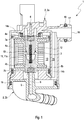
- Fig. 1 shows a sectional view of a double armature solenoid valve 1 according to the invention for draining water from an intake-side fuel filter system of a motor vehicle.
- the double armature solenoid valve 1 has a valve housing 2 which, in this exemplary embodiment, is formed in two parts from a cup-shaped housing part 2a and a cover 2b.
- the cover 2b is in the housing part 2a and sealed to this by an annular seal 19.
- a guide space 3 is formed, in which a first armature 4a and a second armature 4b are arranged opposite one another.
- the two anchors 4a and 4b are adjustable within the guide space 3 along a common adjustment axis 5 axially towards one another into an open position and axially away from one another into a closed position - as shown here.
- the first armature 4a is assigned to an air inlet channel 6 and, in the closed position - as shown here - lies in a sealing manner with a first sealing means 7a on an opening 8a of the air inlet channel 6.
- the mouth 8a of the air inlet channel 6 here forms a valve seat for the first armature 4a.
- the second anchor 4b is assigned to a water drainage channel 9 and, in the closed position - as shown here - lies in a sealing manner with a second sealing means 7b on an opening 8b of the water drainage channel 9.
- the mouth 8b of the water drainage channel 9 here forms a valve seat for the second armature 4b.
- the first sealant 7a and the second sealant 7b are appropriately formed from an elastic, water and fuel-resistant material.
- a stop 10 is formed between the two anchors 4a and 4b and projects radially into the guide space 3.
- the two armatures 4a and 4b can be guided between the stop 10 and the respective valve seat in the guide space 3 along the adjustment axis 5.
- the two armatures 4a and 4b are in contact with the stop 10 and in the closed position - as shown here - the two armatures 4a and 4b are in sealing contact with the respective mouths 8a and 8b.
- the closed position the air inlet channel 6 and the water outlet channel 9 are accordingly closed and in the open position the air inlet channel 6 and the water outlet channel 9 are open.
- the double armature solenoid valve 1 also has a return spring 11 - here a single helical spring 11a.
- the return spring 11 is arranged between the two armatures 4a and 4b and is axially supported directly on the two armatures 4a and 4b.
- the return spring 11 presses the two armatures 4a and 4b axially away from one another into the closed position.
- a coil 12 is also arranged around the guide space 3 and correspondingly around the two armatures 4a and 4b.
- the coil 12 can generate a magnetic flux in the two armatures 4a and 4b and adjust them against the spring force of the return spring 11 from the closed position into the open position.
- the two armatures 4a and 4b are appropriately formed from a material in which the magnetic flux can be generated.
- Fig. 1 the two armatures 4a and 4b are in the closed position and are pressed sealingly against the respective mouths 8a and 8b by the spring force of the return spring 11.
- the coil 12 is switched off and does not generate any magnetic flux in the two armatures 4a and 4b.
- the coil 12 To move the two armatures 4a and 4b into the open position, the coil 12 generates the magnetic flux in the two armatures 4a and 4b.
- the two anchors 4a and 4b move against the spring force of the return spring 11 towards each other up to the stop 10.
- the air inlet duct 6 and the water outlet duct 9 are open.
- the two armatures 4a and 4b are moved into the closed position by the return spring 11.
- the air inlet channel 6 and the water outlet channel 9 are closed.
- the coil 12 is protected from water in a coil space 13 within the valve housing 2 by annular seals 14a and 14b.
- the seals 14a and 14b are suitably formed from a resilient material and are water and fuel resistant.
- the double armature solenoid valve 1 also has a water inlet space 15, which is arranged within the valve housing 2.
- the water inlet space 15 is regional formed around the first armature 4a and around the second armature 4b and can be connected to a water collection area of the suction-side fuel filter system - see Fig. 4 - be fluidically connected.
- a contact stub 17 with a water inlet opening 16 is formed on the valve housing 2.
- the contact socket 17 can form a housing around the water collection area via an annular seal 18 - see also Fig. 4 - be sealed.
- the first anchor 4a fluidly separates the air inlet channel 6 from the water inlet space 15 and in the open position the first anchor 4a fluidically connects the air inlet channel 6 to the water inlet space 15.
- the second separates Anchor 4b fluidly connects the water drainage channel 9 from the water inlet space 15 and, in the open position, the second anchor 4b fluidically connects the water drainage channel 9 to the water inlet space 15.
- the air inlet duct 6, the water outlet duct 9, the water inlet chamber 15 and the water collection area of the suction-side fuel filter system are fluidically connected to one another.
- the water collected in the water collecting area then flows through the water inlet opening 16 into the water inlet space 15 and out of the water inlet space 15 through the open water drainage channel 9 out of the double armature solenoid valve 1.
- the air flows through the open air inlet duct 6 into the water inlet space 15 and out of the water inlet space 15 through the water inlet opening 16 into the water collection area of the fuel filter system and compensates for the negative pressure there.
- the first armature 4a and the air inlet duct 6 are not in the flow path, so that no pressure loss is caused in the suction-side fuel filter system.
- the air inlet duct 6 is arranged above the water inlet opening 16, so that the air can flow into the water inlet space 15 unhindered when the air inlet duct 6 is open. Furthermore, the first anchor 4a is arranged above the second anchor 4b and, as a result, the air inlet channel 6 is arranged above the water drainage channel 9. The discharge of the water from the water collection area of the fuel filter system consequently takes place under the action of the force of gravity. In the closed position - as shown here - the two armatures 4a and 4b and, accordingly, the air inlet duct 6 and the water drainage duct 9 are closed.
- a negative pressure prevails in the suction-side fuel filter system and in the water collection area, so that the water cannot drain from the water collection area via the built-in double armature solenoid valve 1.
- the first armature 4a also serves as a safety valve in the double armature solenoid valve 1.
- FIGS. 2 and 3 show views of the double-armature solenoid valve 1.
- fastening openings 20a and 20b through which the double-armature solenoid valve 1 can be fixed in the motor vehicle are visible here.
- Compression systems 21a and 21b are arranged within the fastening openings 20a and 20b.
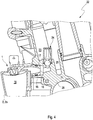
- Fig. 4 shows a sectional view of a suction-side fuel filter system 22 with the double armature solenoid valve 1 according to the invention and with a water collecting area 23.
- the water inlet space 15 of the double armature solenoid valve 1 - only partially shown here - is fluidically connected to the water collecting area 23 of the fuel filter system 22.
- the contact stub 17 is fixed to a housing 26 around the water collecting area 23 and is sealed off from it by the ring seal 18.
- a ball seat valve 24 with a floating ball 25 is also arranged at the water inlet opening 16.
- the floating ball 25 has a correspondingly adapted density, which lies between the density of the water and the fuel.
Landscapes
- Engineering & Computer Science (AREA)
- General Engineering & Computer Science (AREA)
- Mechanical Engineering (AREA)
- Chemical & Material Sciences (AREA)
- Combustion & Propulsion (AREA)
- Physics & Mathematics (AREA)
- Electromagnetism (AREA)
- Magnetically Actuated Valves (AREA)
Description
- Die Erfindung betrifft ein Doppelankermagnetventil zum Ablassen von Wasser aus einem saugseitigen Kraftstofffiltersystem eines Kraftfahrzeugs. Die Erfindung betrifft auch ein saugseitiges Kraftstofffiltersystem eines Kraftfahrzeugs.
- Ein Kraftstofffiltersystem in einem Kraftfahrzeug ist zum Filtern des Kraftstoffs vorgesehen und umfasst üblicherweise ein Wassersammelsystem zum Sammeln vom abgeschiedenen Wasser aus dem Kraftstoff. Besteht bauraumtechnisch keine Möglichkeit das Wasser händisch aus dem Wassersammelsystem auszutragen, so kann ein automatisches oder semi-automatisches Ablasssystem mit einem Magnetventil eingesetzt werden. Das Magnetventil öffnet dann das Wassersammelsystem automatisch oder semi-automatisch und das gesammelte Wasser kann aus dem Wassersammelsystem entfernt und vorschriftsgemäß entsorgt werden. Derartige Magnetventile sind für druckseitige Kraftstofffiltersysteme beispielweise aus
DE 10 2016 110 899 A1 undDE 10 2014 216 409 A1 bekannt. Dabei werden in dem druckseitigen Kraftstofffiltersystem zur Steigerung der Funktionssicherheit entweder zwei Magnetventile eingesetzt oder das eine Magnetventil zusätzlich überwacht. Da ein saugseitiges Kraftstofffiltersystem sich von einem druckseitigen Kraftstofffiltersystem grundsätzlich unterscheidet, kann nachteiligerweise ein Magnetventil für das druckseitige Kraftstofffiltersystem nicht in einem saugseitigen Kraftstofffiltersystem verwendet werden Außerdem beschreibt auchDE 11 2016 002 713 T5 ein Magnetventil mit einem axial verstellbaren Anker zum Ablassen von Wasser aus einem Kraftstofffiltersystem. Um den Anker ist ein Wasserzulaufraum angeordnet, der über eine Wasserzulauföffnung mit einem Wassersammelbereich fluidisch verbindbar ist. In einer Schließposition trennt der Anker einen Luftzulaufkanal und einen Wasserablaufkanal von dem Wasserzulaufraum fluidisch. In einer Öffnungsposition verbindet der Anker den Luftzulaufkanal und den Wasserablaufkanal mit dem Wasserzulaufraum fluidisch, so dass Luft einen Unterdruck im Wassersammelbereich ausgleichen kann, und somit Wasser aus dem Wassersammelbereich über den Wasserzulaufraum und den Wasserablaufkanal abfließen kann. Die Herstellung eines solchen Magnetventils ist besonders aufwendig, weil der Anker zwei Kanäle (Luftzulaufkanal und Wasserablaufkanal) gleichzeitig dicht schließen bzw. gleichzeitig öffnen soll. Eine Undichtheit in einem der beiden Kanäle kann Funktionsstörungen des Kraftstofffiltersystem verursachen. - Die Aufgabe der Erfindung ist es daher, für ein Doppelankermagnetventil und ein Kraftstofffiltersystem mit dem Doppelankermagnetventil der gattungsgemäßen Art eine verbesserte oder zumindest alternative Ausführungsform anzugeben, bei der die beschriebenen Nachteile überwunden werden.
- Diese Aufgabe wird erfindungsgemäß durch den Gegenstand der unabhängigen Ansprüche gelöst. Vorteilhafte Ausführungsformen sind Gegenstand der abhängigen Ansprüche.
- Ein erfindungsgemäßes Doppelankermagnetventil ist zum Ablassen von Wasser aus einem saugseitigen Kraftstofffiltersystem eines Kraftfahrzeugs vorgesehen. Das Doppelankermagnetventil weist dabei einen ersten Anker und einen zweiten Anker auf, die einander gegenüberliegend angeordnet sind und entlang einer gemeinsamen Verstellachse axial aufeinander zu in eine Öffnungsposition und axial voneinander weg in eine Schließposition verstellbar sind. Das Doppelankermagnetventil weist ferner wenigstens eine Rückstellfeder und wenigstens eine zumindest teilweise um die Anker angeordnete Spule auf. Dabei drückt die Rückstellfeder die beiden Anker aus der Öffnungsposition in die Schließposition. Die wenigstens eine Spule kann einen magnetischen Fluss in den beiden Ankern erzeugen und diese gegen die Federkraft der Rückstellfeder aus der Schließposition in die Öffnungsposition verstellen. Das Doppelankermagnetventil weist zudem einen Wasserzulaufraum auf, der zumindest bereichsweise um den zweiten Anker angeordnet ist und über eine Wasserzulauföffnung mit einem Wassersammelbereich des Kraftstofffiltersystems fluidisch verbindbar ist. Der erste Anker ist dabei einem Luftzulaufkanal zum Einlassen von Luft in den Wasserzulaufraum zugeordnet. In der Schließposition trennt der erste Anker den Luftzulaufkanal fluidisch von dem Wasserzulaufraum und in der Öffnungsposition verbindet der erste Anker den Luftzulaufkanal fluidisch mit dem Wasserzulaufraum. Der zweite Anker ist einem Wasserablaufkanal zum Ablaufen von Wasser aus dem Wasserzulaufraum zugeordnet. In der Schließposition trennt der zweite Anker den Wasserablaufkanal fluidisch von dem Wasserzulaufraum und in der Öffnungsposition verbindet der zweite Anker den Wasserablaufkanal fluidisch mit dem Wasserzulaufraum. In der Öffnungsposition kann Luft aus dem Luftzulaufkanal in den Wasserzulaufraum und aus dem Wasserzulaufraum über die Wasserzulauföffnung in den Wassersammelbereich des Kraftstofffiltersystems gelangen und kann einen Unterdruck in dem Wassersammelbereich des Kraftstofffiltersystems ausgleichen. Dadurch kann das Wasser aus dem Wassersammelbereich des Kraftstofffiltersystems in den Wasserzulaufraum und aus dem Wasserzulaufraum über den geöffneten Wasserablaufkanal abfließen.
- In der vorliegenden Erfindung bezieht sich der Begriff "betriebsgeeignet ausgerichtet" auf eine Ausrichtung des Doppelankermagnetventils, in der das Doppelankermagnetventil wie vorgesehen betrieben werden kann. In der vorliegenden Erfindung ist das Doppelankermagnetventil betriebsgeeignet ausgerichtet, wenn das Austragen des Wassers nach dem Verstellen der beiden Anker in die Öffnungsposition unter der Wirkung der Erdanziehungskraft erfolgen kann. Die Begriffe "oberhalb" und "unterhalb" sind dabei auf die Ausrichtung der Erdanziehungskraft in dem betriebsgeeignet ausgerichteten Doppelankermagnetventil bezogen. Der Begriff "eingebaut" bezieht sich dabei auf das Doppelankermagnetventil, das mit dem Wassersammelbereich des Kraftstofffiltersystems über die Wasserzulauföffnung fluidisch verbunden ist. Der Wassersammelbereich des Kraftstofffiltersystems und das Kraftstofffiltersystem sind jedoch kein Teil des Doppelankermagnetventils und werden lediglich zur Erläuterung der Funktion des Doppelankermagnetventils herangezogen.
- Durch das eingebaute Doppelankermagnetventil kann der Unterdruck in dem Wassersammelbereich des Kraftstofffiltersystems vorteilhaft ausgeglichen werden. Beim Austragen des Wassers aus dem Wassersammelbereich sind die beiden Anker in der Öffnungsposition, so dass der Luftzulaufkanal und der Wasserablaufkanal geöffnet und über den Wasserzulaufraum fluidisch miteinander verbunden sind. Das in dem Wassersammelbereich angesammelte Wasser strömt über die Wasserzulauföffnung in den Wasserzulaufraum und aus dem Wasserzulaufraum über den geöffneten Wasserablaufkanal aus dem Kraftstofffiltersystem und kann gesammelt und vorschriftsgemäß entsorgt werden. Gleichzeitig strömt die Luft über den geöffneten Luftzulaufkanal in den Wasserzulaufraum und aus dem Wasserzulaufraum über die Wasserzulauföffnung in den Wassersammelbereich des Kraftstofffiltersystems und kann den Unterdruck in dem Wassersammelbereich ausgleichen. Dabei liegen der erste Anker und entsprechend der Luftzulaufkanal beim Austragen des Wassers nicht in seinem Strömungsweg, so dass kein Druckverlust verursacht wird. In der Schließposition der beiden Anker sind der Luftzulaufkanal und der Wasserablaufkanal geschlossen. In dem Wassersammelbereich des saugseitigen Kraftstofffiltersystems herrscht dabei ein Unterdruck, so dass das Wasser aus dem Wassersammelbereich über das Doppelankermagnetventil nicht ablaufen kann. Der erste Anker dient zudem als ein Sicherheitsventil in dem Doppelankermagnetventil.
- Vorteilhafterweise kann vorgesehen sein, dass eine Mündung des Luftzulaufkanals und eine Mündung des Wasserablaufkanals in dem Wasserzulaufraum einander axial gegenüberliegen und jeweils einen Ventilsitzt für den jeweiligen Anker bilden. Vorteilhafterweise ist dadurch das Doppelankermagnetventil unempfindlich gegenüber einer Schräglage in Bezug auf die Erdanziehungskraft und das Austragen des Wassers aus dem Wassersammelbereich des Kraftstofffiltersystems kann nach dem Überführen der beiden Anker in die Öffnungsposition auch in einer Schräglage ungehindert erfolgen. Die beiden Anker sind ferner durch die wenigstens eine gemeinsame Spule betätigbar, jedoch physisch voneinander getrennt. Dadurch ist eine Gefahr des Verklemmens des Doppelankermagnetventils im Vergleich zu herkömmlichen Lösungen minimiert.
- Bei einer Weiterbildung des Doppelankermagnetventils ist vorgesehen, dass der erste Anker und der zweite Anker beim Erzeugen eines magnetischen Flusses durch die wenigstens eine Spule in die Öffnungsposition oder durch die Rückstellfeder in die Schließposition zueinander verzögerungsfrei bringbar sind. Dazu kann vorgesehen sein, dass auf die beiden Anker durch den magnetischen Fluss der wenigstens einen Spule gleiche Öffnungskraft wirkt. Ferner kann die wenigstens eine Rückstellfeder eine gleiche Federkraft auf die beiden Anker ausüben. Die beiden Anker können beispielweise um einen gleichen Verstellweg entlang der Verstellachse verstellbar sein und zudem eine gleiche Masse aufweisen. Ferner können die beiden Anker aus einem identischen Material geformt sein. Insbesondere kann dadurch der Aufbau des Doppelankermagnetventils im Vergleich zu herkömmlichen Lösungen deutlich vereinfacht sein.
- Vorteilhafterweise kann vorgesehen sein, dass die wenigstens eine Rückstellfeder eine einzelne Schraubenfeder ist, die zwischen den beiden Ankern angeordnet ist und sich axial unmittelbar auf den ersten Anker und auf den zweiten Anker abstützt. Die Schraubenfeder drückt die beiden Anker entlang der Verstellachse axial voneinander weg in die Schließposition. Durch die einzelne Schraubenfeder kann der Aufbau des Doppelankermagnetventils vereinfacht werden.
- Bei einer Weiterbildung des Doppelankermagnetventils ist vorgesehen, dass in dem betriebsgeeignet ausgerichteten Doppelankermagnetventil der Luftzulaufkanal zumindest bereichsweise oberhalb der Wasserzulauföffnung angeordnet ist. Dadurch kann Luft über den geöffneten Luftzulaufkanal in den Wasserzulaufraum ungehindert einströmen und dadurch bei dem eingebauten Doppelankermagnetventil den Unterdruck in dem Wassersammelbereich des saugseitigen Kraftstofffiltersystems ausgleichen. Vorteilhafterweise können in dem betriebsgeeignet ausgerichteten Doppelankermagnetventil der erste Anker oberhalb des zweiten Ankers und dadurch der Luftzulaufkanal oberhalb des Wasserablaufkanals angeordnet sein.
- Bei einer vorteilhaften Ausführungsform des Doppelankermagnetventils ist vorgesehen, dass das Doppelankermagnetventil in dem Luftzulaufkanal ein erstes Kugelsitzventil aufweist. Sind das Doppelankermagnetventil betriebsgeeignet ausgerichtet und der erste Anker in der Öffnungsposition, so ist der Luftzulaufkanal bei einem Überdruck in dem Wasserzulaufraum durch das erste Kugelsitzventil gesperrt und bei einem Unterdruck in dem Wasserzulaufraum durch das erste Kugelsitzventil freigegeben. Auf diese vorteilhafte Weise kann ein Austragen des Wassers über den Luftzulaufkanal verhindert werden, falls bei dem eingebauten Doppelankermagnetventil in dem Wasserzulaufraum ausnahmeweise ein Überdruck herrscht.
- Vorteilhafterweise kann das Doppelankermagnetventil ein zweites Kugelsitzventil an der Wasserzulauföffnung aufweisen. Sind das Doppelankermagnetventil betriebsgeeignet ausgerichtet und der erste Anker in der Öffnungsposition, ist die Wasserzulauföffnung beim Durchströmen des Wassers durch das zweite Kugelsitzventil freigegeben und beim Durchströmen des Kraftstoffs durch das zweite Kugelsitzventil gesperrt. Dadurch kann ein Austragen des Kraftstoffs durch das eingebaute Doppelankermagnetventil verhindert werden. Dabei kann vorgesehen sein, dass das zweite Kugelsitzventil eine Schwimmkugel mit einer Dichte zwischen der Dichte des Wasser und der Dichte des Kraftstoffs aufweist. In dem eingebauten Doppelankermagnetventil schwimmt dann die Schwimmkugel in dem Kraftstoff auf und sperrt die Wasserzulauföffnung.
- Vorteilhafterweise kann vorgesehen sein, dass die beiden Anker in einem Führungsraum entlang der Verstellachse führbar angeordnet sind. Dabei ist in dem Führungsraum für die beiden Anker wenigstens ein Anschlag ausgebildet, an dem die beiden Anker in der Öffnungsposition anliegen. Der erste Anker ist somit innerhalb des Führungsraums entlang der Verstellachse zwischen einer von ihm schließbaren Mündung des Luftzulaufkanals in den Wasserzulaufraum und dem Anschlag führbar. Liegt der erste Anker an der Mündung des Luftzulaufkanals, so sind der Anker in der Schließposition und der Luftzulaufkanal geschlossen. Liegt der erste Anker an dem Anschlag, so sind der erste Anker in der Öffnungsposition und der Luftzulaufkanal geöffnet. Entsprechendes gilt auch für den zweiten Anker, der zwischen einer von ihm schließbaren Mündung des Wasserablaufkanals in den Wasserzulaufraum und dem Anschlag führbar ist. Die beiden Anker können beispielweise zylinderförmig und der Führungsraum hohlzylindrisch ausgestaltet sein. Grundsätzlich sind auch andere Formen denkbar.
- Zum fluiddichten Schließen des Luftzulaufkanals kann an dem ersten Anker ein erstes Dichtmittel festgelegt sein. Das erste Dichtmittel dichtet dabei in der Schließposition des ersten Ankers den Luftzulaufkanal zu dem Wasserzulaufraum ab. Das erste Dichtmittel kann dabei in der Schließposition um eine Mündung des Luftzulaufkanals in den Wasserzulaufraum dichtend anliegen und durch die Federkraft der Rückstellfeder mit der Mündung zusätzlich verpresst sein. An dem zweiten Anker kann ein zweites Dichtmittel festgelegt sein, das in der Schließposition des zweiten Ankers den Wasserablaufkanal zu dem Wasserzulaufraum abdichtet. Das zweite Dichtmittel kann dabei in der Schließposition um eine Mündung des Wasserablaufkanals in den Wasserzulaufraum dichtend anliegen und durch die Federkraft der Rückstellfeder mit der Mündung zusätzlich verpresst sein. Das erste Dichtmittel und das zweite Dichtmittel können aus einem elastischen Material geformt sein, das zweckgemäß wasser- und kraftstoffbeständig ist.
- Die Erfindung betrifft auch ein saugseitiges Kraftstofffiltersystem eines Kraftfahrzeugs mit einem Wassersammelbereich zum Sammeln von abgeschiedenem Wasser aus dem Kraftstoff und mit dem oben beschriebenen Doppelankermagnetventil. Der Wassersammelbereich ist dabei mit dem Doppelankermagnetventil fluidisch verbunden, so dass das Wasser aus dem Wassersammelbereich des Kraftstofffiltersystems über das Doppelankermagnetventil abfließen kann.
- Weitere wichtige Merkmale und Vorteile der Erfindung ergeben sich aus den Unteransprüchen, aus den Zeichnungen und aus der zugehörigen Figurenbeschreibung anhand der Zeichnungen.
- Bevorzugte Ausführungsbeispiele der Erfindung sind in den Zeichnungen dargestellt und werden in der nachfolgenden Beschreibung näher erläutert, wobei sich gleiche Bezugszeichen auf gleiche oder ähnliche oder funktional gleiche Komponenten beziehen.
- Es zeigen, jeweils schematisch
- Fig. 1
- eine Schnittansicht eines erfindungsgemäßen Doppelankermagnetventils;
- Fig. 2 und 3
- Ansichten des erfindungsgemäßen Doppelankermagnetventils;
- Fig. 4
- eine Schnittansicht eines saugseitigen Kraftstofffiltersystems mit dem erfindungsgemäßen Doppelankermagnetventil.
-
Fig. 1 zeigt eine Schnittansicht eines erfindungsgemäßen Doppelankermagnetventils 1 zum Ablassen von Wasser aus einem saugseitigen Kraftstofffiltersystem eines Kraftfahrzeugs. Das Doppelankermagnetventil 1 weist ein Ventilgehäuse 2 auf, das in diesem Ausführungsbeispiel zweiteilig aus einem topfförmigen Gehäuseteil 2a und einem Deckel 2b gebildet ist. Der Deckel 2b ist in dem Gehäuseteil 2a festgelegt und zu diesem durch eine Ringdichtung 19 abgedichtet. In dem Gehäuseteil 2a des Ventilgehäuses 2 ist ein Führungsraum 3 ausgebildet, in dem ein erster Anker 4a und ein zweiter Anker 4b einander gegenüberliegend angeordnet sind. Die beiden Anker 4a und 4b sind innerhalb des Führungsraumes 3 entlang einer gemeinsamen Verstellachse 5 axial aufeinander zu in eine Öffnungsposition und axial voneinander weg in eine Schließposition - wie hier gezeigt - verstellbar. - Der erste Anker 4a ist dabei einem Luftzulaufkanal 6 zugeordnet und liegt in der Schließposition - wie hier gezeigt - mit einem ersten Dichtmittel 7a an einer Mündung 8a des Luftzulaufkanals 6 dichtend an. Die Mündung 8a des Luftzulaufkanals 6 bildet hier einen Ventilsitz für den ersten Anker 4a. Der zweite Anker 4b ist einem Wasserablaufkanal 9 zugeordnet und liegt in der Schließposition - wie hier gezeigt - mit einem zweiten Dichtmittel 7b an einer Mündung 8b des Wasserablaufkanals 9 dichtend an. Die Mündung 8b des Wasserablaufkanals 9 bildet hier einen Ventilsitz für den zweiten Anker 4b. Das erste Dichtmittel 7a und das zweite Dichtmittel 7b sind zweckgemäß aus einem elastischen, wasser- und kraftstoffbeständigen Material geformt.
- Zwischen den beiden Ankern 4a und 4b ist ein Anschlag 10 ausgeformt, der radial in den Führungsraum 3 hineinragt. Die beiden Anker 4a und 4b sind zwischen dem Anschlag 10 und dem jeweiligen Ventilsitz in dem Führungsraum 3 entlang der Verstellachse 5 führbar. In der Öffnungsposition liegen dabei die beiden Anker 4a und 4b an dem Anschlag 10 an und in der Schließposition - wie hier gezeigt - liegen die beiden Anker 4a und 4b an der jeweiligen Mündung 8a und 8b dichtend an. In der Schließposition sind demnach der Luftzulaufkanal 6 und der Wasserablaufkanal 9 geschlossen und in der Öffnungsposition sind der Luftzulaufkanal 6 und der Wasserablaufkanal 9 geöffnet.
- Das Doppelankermagnetventil 1 weist ferner eine Rückstellfeder 11 - hier eine einzige Schraubenfeder 11a - auf. Die Rückstellfeder 11 ist zwischen den beiden Ankern 4a und 4b angeordnet und stützt sich axial unmittelbar auf die beiden Anker 4a und 4b ab. Die Rückstellfeder 11 drückt die beiden Anker 4a und 4b axial voneinander weg in die Schließposition. Um den Führungsraum 3 und entsprechend um die beiden Anker 4a und 4b ist zudem eine Spule 12 angeordnet. Die Spule 12 kann einen magnetischen Fluss in den beiden Ankern 4a und 4b erzeugen und diese gegen die Federkraft der Rückstellfeder 11 aus der Schließposition in die Öffnungsposition verstellen. Die beiden Anker 4a und 4b sind zweckgemäß aus einem Material geformt, in dem der magnetische Fluss erzeugbar ist.
- In
Fig. 1 befinden sich die beiden Anker 4a und 4b in der Schließposition und sind durch die Federkraft der Rückstellfeder 11 an die jeweiligen Mündungen 8a und 8b dichtend angepresst. Die Spule 12 ist ausgeschaltet und erzeugt keinen magnetischen Fluss in den beiden Ankern 4a und 4b. Zum Verstellen der beiden Anker 4a und 4b in die Öffnungsposition wird durch die Spule 12 der magnetische Fluss in den beiden Ankern 4a und 4b erzeugt. Die beiden Anker 4a und 4b bewegen sich gegen die Federkraft der Rückstellfeder 11 aufeinander zu bis zu dem Anschlag 10. Der Luftzulaufkanal 6 und der Wasserablaufkanal 9 sind geöffnet. Sobald die Spule 12 ausgeschaltet ist und keinen magnetischen Fluss in den beiden Ankern 4a und 4b mehr erzeugt, sind die beiden Anker 4a und 4b durch die Rückstellfeder 11 in die Schließposition verstellt. Der Luftzulaufkanal 6 und der Wasserablaufkanal 9 sind geschlossen. Die Spule 12 ist in einem Spulenraum 13 innerhalb des Ventilgehäuses 2 durch ringförmige Dichtungen 14a und 14b vor Wasser geschützt. Die Dichtungen 14a und 14b sind zweckgemäß aus einem elastischen Material geformt und wasser- und kraftstoffbeständig. - Das Doppelankermagnetventil 1 weist ferner einen Wasserzulaufraum 15 auf, der innerhalb des Ventilgehäuses 2 angeordnet ist. Der Wasserzulaufraum 15 ist bereichsweise um den ersten Anker 4a und um den zweiten Anker 4b ausgebildet und kann mit einem Wassersammelbereich des saugseitigen Kraftstofffiltersystems - siehe dazu
Fig. 4 - fluidisch verbunden sein. Dazu ist an dem Ventilgehäuse 2 ein Kontaktstutzen 17 mit einer Wasserzulauföffnung 16 ausgebildet. Der Kontaktstutzen 17 kann zu einem Gehäuse um den Wassersammelbereich über eine Ringdichtung 18 - siehe auchFig. 4 - abgedichtet sein. In der Schließposition - wie hier gezeigt - trennt der erste Anker 4a den Luftzulaufkanal 6 fluidisch von dem Wasserzulaufraum 15 und in der Öffnungsposition verbindet der erste Anker 4a den Luftzulaufkanal 6 fluidisch mit dem Wasserzulaufraum 15. In der Schließposition - wie hier gezeigt - trennt der zweite Anker 4b den Wasserablaufkanal 9 fluidisch von dem Wasserzulaufraum 15 und in der Öffnungsposition verbindet der zweite Anker 4b den Wasserablaufkanal 9 fluidisch mit dem Wasserzulaufraum 15. - Bei dem eingebauten Doppelankermagnetventil 1 und in der Öffnungsposition der beiden Anker 4a und 4b sind folglich der Luftzulaufkanal 6, der Wasserablaufkanal 9, der Wasserzulaufraum 15 und der Wassersammelbereich des saugseitigen Kraftstofffiltersystems fluidisch miteinander verbunden. Das in dem Wassersammelbereich angesammelte Wasser strömt dann über die Wasserzulauföffnung 16 in den Wasserzulaufraum 15 und aus dem Wasserzulaufraum 15 über den geöffneten Wasserablaufkanal 9 aus dem Doppelankermagnetventil 1 raus. Gleichzeitig strömt die Luft über den geöffneten Luftzulaufkanal 6 in den Wasserzulaufraum 15 und aus dem Wasserzulaufraum 15 über die Wasserzulauföffnung 16 in den Wassersammelbereich des Kraftstofffiltersystems und gleicht dort den Unterdruck aus. Der erste Anker 4a und der Luftzulaufkanal 6 liegen dabei nicht im Strömungsweg, so dass kein Druckverlust in dem saugseitigen Kraftstofffiltersystem verursacht wird.
- In dem betriebsgeeignet ausgerichteten Doppelankermagnetventil 1 ist der Luftzulaufkanal 6 oberhalb der Wasserzulauföffnung 16 angeordnet, so dass die Luft bei dem geöffneten Luftzulaufkanal 6 in den Wasserzulaufraum 15 ungehindert einströmen kann. Ferner ist der erste Anker 4a oberhalb des zweiten Ankers 4b und dadurch der Luftzulaufkanal 6 oberhalb des Wasserablaufkanals 9 angeordnet. Das Austragen des Wassers aus dem Wassersammelbereich des Kraftstofffiltersystems erfolgt folglich unter der Wirkung der Erdanziehungskraft. In der Schließposition - wie hier gezeigt - sind die beiden Anker 4a und 4b und entsprechend der Luftzulaufkanal 6 und der Wasserablaufkanal 9 geschlossen. In dem saugseitigen Kraftstofffiltersystem und in dem Wassersammelbereich herrscht dabei ein Unterdruck, so dass das Wasser aus dem Wassersammelbereich über das eingebaute Doppelankermagnetventil 1 nicht ablaufen kann. Der erste Anker 4a dient zudem als ein Sicherheitsventil in dem Doppelankermagnetventil 1.
-
Fig. 2 und Fig. 3 zeigen Ansichten des Doppelankermagnetventils 1. Insbesondere sind hier Befestigungsöffnungen 20a und 20b sichtbar, durch die das Doppelankermagnetventil 1 in dem Kraftfahrzeug festlegbar ist. Innerhalb der Befestigungsöffnungen 20a und 20b sind Kompressionsanlagen 21a und 21b angeordnet. -
Fig. 4 zeigt eine Schnittansicht eines saugseitigen Kraftstofffiltersystems 22 mit dem erfindungsgemäßen Doppelankermagnetventil 1 und mit einem Wassersammelbereich 23. Der Wasserzulaufraum 15 des Doppelankermagnetventils 1 - hier nur teilweise gezeigt - ist mit dem Wassersammelbereich 23 des Kraftstofffiltersystems 22 fluidisch verbunden. Dazu ist der Kontaktstutzen 17 an einem Gehäuse 26 um den Wassersammelbereich 23 festgelegt und durch die Ringdichtung 18 zu diesem abgedichtet. In dem Kraftstofffiltersystem 22 ist zudem an der Wasserzulauföffnung 16 ein Kugelsitzventil 24 mit einer Schwimmkugel 25 angeordnet. Sind die beiden Anker 4a und 4b - hier nicht sichtbar - in der Öffnungsposition, so ist die Wasserzulauföffnung 16 beim Durchströmen des Wassers durch das Kugelsitzventil 24 freigegeben und beim Durchströmen des Kraftstoffs durch das Kugelsitzventil 24 gesperrt. Dadurch kann ein Austragen des Kraftstoffs durch das Doppelankermagnetventil 1 verhindert werden. Die Schwimmkugel 25 weist eine entsprechend angepasste Dichte auf, die zwischen der Dichte des Wassers und des Kraftstoffs liegt.
Claims (11)
- Doppelankermagnetventil (1) zum Ablassen von Wasser aus einem saugseitigen Kraftstofffiltersystem (22) eines Kraftfahrzeugs,- wobei das Doppelankermagnetventil (1) einen ersten Anker (4a) und einen zweiten Anker (4b) aufweist, die einander gegenüberliegend angeordnet sind und entlang einer gemeinsamen Verstellachse (5) axial aufeinander zu in eine Öffnungsposition und axial voneinander weg in eine Schließposition verstellbar sind,- wobei das Doppelankermagnetventil (1) wenigstens eine Rückstellfeder (11) und wenigstens eine zumindest teilweise um die die Anker (4a, 4b) angeordnete Spule (12) aufweist,- wobei die Rückstellfeder (11) die beiden Anker (4a, 4b) aus der Öffnungsposition in die Schließposition drückt und die wenigstens eine Spule (12) einen magnetischen Fluss in den beiden Ankern (4a, 4b) erzeugen und diese gegen die Federkraft der Rückstellfeder (11) aus der Schließposition in die Öffnungsposition verstellen kann,- wobei das Doppelankermagnetventil (1) einen Wasserzulaufraum (15) aufweist, der zumindest bereichsweise um den zweiten Anker (4b) angeordnet ist und über eine Wasserzulauföffnung (16) mit einem Wassersammelbereich (23) des Kraftstofffiltersystems (22) fluidisch verbindbar ist,- wobei der erste Anker (4a) einem Luftzulaufkanal (6) zum Einlassen von Luft in den Wasserzulaufraum (15) zugeordnet ist und in der Schließposition den Luftzulaufkanal (6) von dem Wasserzulaufraum (15) fluidisch trennt und in der Öffnungsposition den Luftzulaufkanal (6) mit dem Wasserzulaufraum (15) fluidisch verbindet,- wobei der zweite Anker (4b) einem Wasserablaufkanal (9) zum Ablaufen von Wasser aus dem Wasserzulaufraum (15) zugeordnet ist und in der Schließposition den Wasserablaufkanal (9) von dem Wasserzulaufraum (15) fluidisch trennt und in der Öffnungsposition den Wasserablaufkanal (9) mit dem Wasserzulaufraum (15) fluidisch verbindet,- wobei in der Öffnungsposition Luft aus dem Luftzulaufkanal (6) in den Wasserzulaufraum (15) und aus dem Wasserzulaufraum (15) über die Wasserzulauföffnung (16) in den Wassersammelbereich (23) des Kraftstofffiltersystems (22) gelangen und einen Unterdruck in dem Wassersammelbereich (23) des Kraftstofffiltersystems (22) ausgleichen kann, so dass das Wasser aus dem Wassersammelbereich (23) des Kraftstofffiltersystems (22) in den Wasserzulaufraum (15) und aus dem Wasserzulaufraum (15) über den geöffneten Wasserablaufkanal (9) abfließen kann.
- Doppelankermagnetventil nach Anspruch 1,
dadurch gekennzeichnet,
dass eine Mündung (8a) des Luftzulaufkanals (6) und eine Mündung (8b) des Wasserablaufkanals (9) in dem Wasserzulaufraum (15) einander axial gegenüberliegen und jeweils einen Ventilsitzt für den jeweiligen Anker (4a, 4b) bilden. - Doppelankermagnetventil nach Anspruch 1 oder 2,
dadurch gekennzeichnet,
dass der erste Anker (4a) und der zweite Anker (4b) beim Erzeugen eines magnetischen Flusses durch die wenigstens eine Spule (12) in die Öffnungsposition oder durch die Rückstellfeder (11) in die Schließposition zueinander verzögerungsfrei bringbar sind. - Doppelankermagnetventil nach einem der vorangehenden Ansprüche,
dadurch gekennzeichnet,
dass die wenigstens eine Rückstellfeder (11) eine einzelne Schraubenfeder (11a) ist, die zwischen den beiden Ankern (4a, 4b) angeordnet ist und sich axial unmittelbar auf den ersten Anker (4a) und auf den zweiten Anker (4b) abstützt. - Doppelankermagnetventil nach einem der vorangehenden Ansprüche,
dadurch gekennzeichnet,- dass in dem betriebsgeeignet ausgerichteten Doppelankermagnetventil (1) der Luftzulaufkanal (6) zumindest bereichsweise oberhalb der Wasserzulauföffnung (16) angeordnet ist, so dass Luft über den Luftzulaufkanal (6) in den Wasserzulaufraum (15) einströmen kann, und/oder- dass in dem betriebsgeeignet ausgerichteten Doppelankermagnetventil (1) der erste Anker (4a) oberhalb des zweiten Ankers (4b) und dadurch der Luftzulaufkanal (6) oberhalb des Wasserablaufkanals (9) in den Wasserzulaufraum (15) einmünden. - Doppelankermagnetventil nach einem der vorangehenden Ansprüche,
dadurch gekennzeichnet,
dass das Doppelankermagnetventil (1) in dem Luftzulaufkanal (6) ein erstes Kugelsitzventil aufweist, das in dem betriebsgeeignet ausgerichteten Doppelankermagnetventil (1) in der Öffnungsposition des ersten Ankers (4a) und bei einem Überdruck in dem Wasserzulaufraum (15) den Luftzulaufkanal (6) sperrt und in der Öffnungsposition des ersten Ankers (4a) und bei einem Unterdruck in dem Wasserzulaufraum (15) freigibt. - Doppelankermagnetventil nach einem der vorangehenden Ansprüche,
dadurch gekennzeichnet,
dass das Doppelankermagnetventil (1) an der Wasserzulauföffnung (16) ein zweites Kugelsitzventil (24) aufweist, das in dem betriebsgeeignet ausgerichteten Doppelankermagnetventil (1) beim Durchströmen des Wassers durch das zweite Kugelsitzventil (24) die Wasserzulauföffnung (16) freigibt und beim Durchströmen des Kraftstoffs durch das zweite Kugelsitzventil (24) die Wasserzulauföffnung (16) sperrt. - Doppelankermagnetventil nach Anspruch 7,
dadurch gekennzeichnet,
dass das zweite Kugelsitzventil (24) eine Schwimmkugel (25) mit einer Dichte zwischen der Dichte des Wasser und der Dichte des Kraftstoffs aufweist, so dass in dem betriebsgeeignet ausgerichteten Doppelankermagnetventil (1) die Schwimmkugel (25) in dem Kraftstoff aufschwimmt und das Durchströmen durch die Wasserzulauföffnung sperrt. - Doppelankermagnetventil nach einem der vorangehenden Ansprüche,
dadurch gekennzeichnet,- dass an dem ersten Anker (4a) ein erstes Dichtmittel (7a) festgelegt ist, das in der Schließposition des ersten Ankers (4a) den Luftzulaufkanal (6) zu dem Wasserzulaufraum (15) abdichtet, und/oder- dass an dem zweiten Anker (4b) ein zweites Dichtmittel (7b) festgelegt ist, das in der Schließposition des zweiten Ankers (4b) den Wasserablaufkanal (9) zu dem Wasserzulaufraum (15) abdichtet. - Doppelankermagnetventil nach einem der vorangehenden Ansprüche,
dadurch gekennzeichnet,- dass die beiden Anker (4a, 4b) in einem Führungsraum (3) entlang der Verstellachse (5) führbar angeordnet sind, und- dass in dem Führungsraum (3) für die beiden Anker (4a, 4b) wenigstens ein Anschlag (10) ausgebildet ist, an dem die beiden Anker (4a, 4b) in der Öffnungsposition anliegen. - Saugseitiges Kraftstofffiltersystem (22) eines Kraftfahrzeugs,- wobei das Kraftstofffiltersystem (22) einen Wassersammelbereich (23) zum Sammeln von abgeschiedenem Wasser aus dem Kraftstoff und ein Doppelankermagnetventil (1) nach einem der vorangehenden Ansprüche aufweist,- wobei der Wassersammelbereich (23) mit dem Doppelankermagnetventil (1) fluidisch verbunden ist, so dass das Wasser aus dem Wassersammelbereich (23) des Kraftstofffiltersystems über den Doppelankermagnetventil (1) abfließen kann.
Applications Claiming Priority (1)
| Application Number | Priority Date | Filing Date | Title |
|---|---|---|---|
| DE102018218970.6A DE102018218970A1 (de) | 2018-11-07 | 2018-11-07 | Doppelankermagnetventil und ein saugseitiges Kraftstofffiltersystem |
Publications (2)
| Publication Number | Publication Date |
|---|---|
| EP3650682A1 EP3650682A1 (de) | 2020-05-13 |
| EP3650682B1 true EP3650682B1 (de) | 2021-02-24 |
Family
ID=68382191
Family Applications (1)
| Application Number | Title | Priority Date | Filing Date |
|---|---|---|---|
| EP19205449.2A Not-in-force EP3650682B1 (de) | 2018-11-07 | 2019-10-25 | Doppelankermagnetventil und ein saugseitiges kraftstofffiltersystem |
Country Status (2)
| Country | Link |
|---|---|
| EP (1) | EP3650682B1 (de) |
| DE (1) | DE102018218970A1 (de) |
Families Citing this family (1)
| Publication number | Priority date | Publication date | Assignee | Title |
|---|---|---|---|---|
| US12601420B2 (en) * | 2022-12-08 | 2026-04-14 | Depatie Fluid Power Co. | 3/3 way solenoid valve |
Family Cites Families (4)
| Publication number | Priority date | Publication date | Assignee | Title |
|---|---|---|---|---|
| DE102007005916A1 (de) * | 2007-02-01 | 2008-08-14 | Kendrion Binder Magnete Gmbh | Doppelankermagnetventil mit zwei Ventilöffnungen und mindestens einem die Ventilöffnungen verbindenden Kanal |
| DE102014216409A1 (de) | 2014-08-19 | 2016-02-25 | Mahle International Gmbh | Ablasseinrichtung |
| CN111779604B (zh) * | 2015-08-17 | 2022-07-08 | 康明斯过滤Ip公司 | 用于真空侧和压力侧油水分离器的自动排放系统 |
| DE102016110899A1 (de) | 2016-06-14 | 2017-12-14 | Kendrion (Markdorf) Gmbh | Doppelankermagnetventil sowie Betriebsverfahren |
-
2018
- 2018-11-07 DE DE102018218970.6A patent/DE102018218970A1/de not_active Withdrawn
-
2019
- 2019-10-25 EP EP19205449.2A patent/EP3650682B1/de not_active Not-in-force
Non-Patent Citations (1)
| Title |
|---|
| None * |
Also Published As
| Publication number | Publication date |
|---|---|
| EP3650682A1 (de) | 2020-05-13 |
| DE102018218970A1 (de) | 2020-05-07 |
Similar Documents
| Publication | Publication Date | Title |
|---|---|---|
| DE112008000085B4 (de) | Filter mit Installationsintegrität | |
| DE19849742B4 (de) | Ventil des Membrantyps | |
| EP1382810B1 (de) | Ölabscheider für Kurbelgehäuseentlüftung | |
| DE112010000888T5 (de) | "Kein Filter, kein Betrieb" - Fluidfiltrationssysteme | |
| EP1216740A1 (de) | Filteranordnung für Flüssigkeiten | |
| DE20004431U1 (de) | Flüssigkeitsfilter mit Umgehungsventil | |
| DE112010004409B4 (de) | Kombinierter Mechanismus aus Entlastungsventil und Ablassmechanismus, der ein eingesetztes Element zum Gestatten von Ablass in einem Koaleszer-System erfordert | |
| WO2001017658A2 (de) | Filter mit ventil-kombinationsbauteil | |
| DE102008027374A1 (de) | Filter für Betriebsmittel einer Brennkraftmaschine, und Bestandteile eines solchen Filters | |
| DE202018104376U1 (de) | Filtersystem mit automatischem Verschlussstopfen | |
| EP2818653B1 (de) | Rückschlagventil für einen Ölrücklauf in der Kurbelgehäuseentlüftung eines Verbrennungsmotors | |
| DE102014013628B4 (de) | Wasserabscheider mit durch Schwimmerventil gesichertem Wasserüberlauf | |
| EP2558690A1 (de) | Ölnebelabscheider einer kurbelgehäuseentlüftungseinrichtung einer brennkraftmaschine | |
| DE202016104363U1 (de) | Ventil | |
| WO2005007267A1 (de) | Ölfikteranordnung und filterelement | |
| DE102014214877A1 (de) | Tankdrucksteuersolenoid mit passivem Tankunterdruckabbau | |
| EP3650682A1 (de) | Doppelankermagnetventil und ein saugseitiges kraftstofffiltersystem | |
| DE202018103711U1 (de) | Abscheider | |
| DE102016103549B3 (de) | Ventilvorrichtung für eine Verbrennungskraftmaschine | |
| DE102010004778B4 (de) | Ventil zur Steuerung eines Fluidstromes | |
| EP3558485A1 (de) | Fluidablaufsteuerung mittels dichtungsanordnung | |
| DE102004063015A1 (de) | Kraftstofffilter | |
| EP0195389B1 (de) | Rohrtrenner | |
| EP0773053A1 (de) | Filter für in einen geschlossenen Behälter zurückfliessende Flüssigkeit | |
| EP0634529B1 (de) | Systemtrenner |
Legal Events
| Date | Code | Title | Description |
|---|---|---|---|
| PUAI | Public reference made under article 153(3) epc to a published international application that has entered the european phase |
Free format text: ORIGINAL CODE: 0009012 |
|
| STAA | Information on the status of an ep patent application or granted ep patent |
Free format text: STATUS: THE APPLICATION HAS BEEN PUBLISHED |
|
| AK | Designated contracting states |
Kind code of ref document: A1 Designated state(s): AL AT BE BG CH CY CZ DE DK EE ES FI FR GB GR HR HU IE IS IT LI LT LU LV MC MK MT NL NO PL PT RO RS SE SI SK SM TR |
|
| AX | Request for extension of the european patent |
Extension state: BA ME |
|
| RIN1 | Information on inventor provided before grant (corrected) |
Inventor name: KIENE, MARCO Inventor name: VOPEL, DAVID Inventor name: GAENSWEIN, MATTHIAS Inventor name: HEGDE, AMIT Inventor name: WILHELM, DIETMAR Inventor name: HAEUSSERMANN, ULI Inventor name: KELLERMANN, STANISLAV |
|
| STAA | Information on the status of an ep patent application or granted ep patent |
Free format text: STATUS: REQUEST FOR EXAMINATION WAS MADE |
|
| 17P | Request for examination filed |
Effective date: 20200804 |
|
| RBV | Designated contracting states (corrected) |
Designated state(s): AL AT BE BG CH CY CZ DE DK EE ES FI FR GB GR HR HU IE IS IT LI LT LU LV MC MK MT NL NO PL PT RO RS SE SI SK SM TR |
|
| GRAP | Despatch of communication of intention to grant a patent |
Free format text: ORIGINAL CODE: EPIDOSNIGR1 |
|
| STAA | Information on the status of an ep patent application or granted ep patent |
Free format text: STATUS: GRANT OF PATENT IS INTENDED |
|
| RIC1 | Information provided on ipc code assigned before grant |
Ipc: F16K 11/14 20060101ALI20200918BHEP Ipc: F16K 31/06 20060101ALI20200918BHEP Ipc: F02M 37/24 20190101AFI20200918BHEP Ipc: F02M 37/28 20190101ALI20200918BHEP |
|
| INTG | Intention to grant announced |
Effective date: 20201019 |
|
| GRAS | Grant fee paid |
Free format text: ORIGINAL CODE: EPIDOSNIGR3 |
|
| GRAA | (expected) grant |
Free format text: ORIGINAL CODE: 0009210 |
|
| STAA | Information on the status of an ep patent application or granted ep patent |
Free format text: STATUS: THE PATENT HAS BEEN GRANTED |
|
| AK | Designated contracting states |
Kind code of ref document: B1 Designated state(s): AL AT BE BG CH CY CZ DE DK EE ES FI FR GB GR HR HU IE IS IT LI LT LU LV MC MK MT NL NO PL PT RO RS SE SI SK SM TR |
|
| REG | Reference to a national code |
Ref country code: CH Ref legal event code: EP |
|
| REG | Reference to a national code |
Ref country code: AT Ref legal event code: REF Ref document number: 1364739 Country of ref document: AT Kind code of ref document: T Effective date: 20210315 |
|
| REG | Reference to a national code |
Ref country code: IE Ref legal event code: FG4D Free format text: LANGUAGE OF EP DOCUMENT: GERMAN |
|
| REG | Reference to a national code |
Ref country code: DE Ref legal event code: R096 Ref document number: 502019000871 Country of ref document: DE |
|
| REG | Reference to a national code |
Ref country code: LT Ref legal event code: MG9D |
|
| REG | Reference to a national code |
Ref country code: NL Ref legal event code: MP Effective date: 20210224 |
|
| PG25 | Lapsed in a contracting state [announced via postgrant information from national office to epo] |
Ref country code: BG Free format text: LAPSE BECAUSE OF FAILURE TO SUBMIT A TRANSLATION OF THE DESCRIPTION OR TO PAY THE FEE WITHIN THE PRESCRIBED TIME-LIMIT Effective date: 20210524 Ref country code: HR Free format text: LAPSE BECAUSE OF FAILURE TO SUBMIT A TRANSLATION OF THE DESCRIPTION OR TO PAY THE FEE WITHIN THE PRESCRIBED TIME-LIMIT Effective date: 20210224 Ref country code: FI Free format text: LAPSE BECAUSE OF FAILURE TO SUBMIT A TRANSLATION OF THE DESCRIPTION OR TO PAY THE FEE WITHIN THE PRESCRIBED TIME-LIMIT Effective date: 20210224 Ref country code: GR Free format text: LAPSE BECAUSE OF FAILURE TO SUBMIT A TRANSLATION OF THE DESCRIPTION OR TO PAY THE FEE WITHIN THE PRESCRIBED TIME-LIMIT Effective date: 20210525 Ref country code: LT Free format text: LAPSE BECAUSE OF FAILURE TO SUBMIT A TRANSLATION OF THE DESCRIPTION OR TO PAY THE FEE WITHIN THE PRESCRIBED TIME-LIMIT Effective date: 20210224 Ref country code: PT Free format text: LAPSE BECAUSE OF FAILURE TO SUBMIT A TRANSLATION OF THE DESCRIPTION OR TO PAY THE FEE WITHIN THE PRESCRIBED TIME-LIMIT Effective date: 20210624 Ref country code: NO Free format text: LAPSE BECAUSE OF FAILURE TO SUBMIT A TRANSLATION OF THE DESCRIPTION OR TO PAY THE FEE WITHIN THE PRESCRIBED TIME-LIMIT Effective date: 20210524 |
|
| PG25 | Lapsed in a contracting state [announced via postgrant information from national office to epo] |
Ref country code: SE Free format text: LAPSE BECAUSE OF FAILURE TO SUBMIT A TRANSLATION OF THE DESCRIPTION OR TO PAY THE FEE WITHIN THE PRESCRIBED TIME-LIMIT Effective date: 20210224 Ref country code: RS Free format text: LAPSE BECAUSE OF FAILURE TO SUBMIT A TRANSLATION OF THE DESCRIPTION OR TO PAY THE FEE WITHIN THE PRESCRIBED TIME-LIMIT Effective date: 20210224 Ref country code: LV Free format text: LAPSE BECAUSE OF FAILURE TO SUBMIT A TRANSLATION OF THE DESCRIPTION OR TO PAY THE FEE WITHIN THE PRESCRIBED TIME-LIMIT Effective date: 20210224 Ref country code: NL Free format text: LAPSE BECAUSE OF FAILURE TO SUBMIT A TRANSLATION OF THE DESCRIPTION OR TO PAY THE FEE WITHIN THE PRESCRIBED TIME-LIMIT Effective date: 20210224 Ref country code: PL Free format text: LAPSE BECAUSE OF FAILURE TO SUBMIT A TRANSLATION OF THE DESCRIPTION OR TO PAY THE FEE WITHIN THE PRESCRIBED TIME-LIMIT Effective date: 20210224 |
|
| PG25 | Lapsed in a contracting state [announced via postgrant information from national office to epo] |
Ref country code: IS Free format text: LAPSE BECAUSE OF FAILURE TO SUBMIT A TRANSLATION OF THE DESCRIPTION OR TO PAY THE FEE WITHIN THE PRESCRIBED TIME-LIMIT Effective date: 20210624 |
|
| PG25 | Lapsed in a contracting state [announced via postgrant information from national office to epo] |
Ref country code: EE Free format text: LAPSE BECAUSE OF FAILURE TO SUBMIT A TRANSLATION OF THE DESCRIPTION OR TO PAY THE FEE WITHIN THE PRESCRIBED TIME-LIMIT Effective date: 20210224 Ref country code: CZ Free format text: LAPSE BECAUSE OF FAILURE TO SUBMIT A TRANSLATION OF THE DESCRIPTION OR TO PAY THE FEE WITHIN THE PRESCRIBED TIME-LIMIT Effective date: 20210224 Ref country code: SM Free format text: LAPSE BECAUSE OF FAILURE TO SUBMIT A TRANSLATION OF THE DESCRIPTION OR TO PAY THE FEE WITHIN THE PRESCRIBED TIME-LIMIT Effective date: 20210224 |
|
| REG | Reference to a national code |
Ref country code: DE Ref legal event code: R097 Ref document number: 502019000871 Country of ref document: DE |
|
| PG25 | Lapsed in a contracting state [announced via postgrant information from national office to epo] |
Ref country code: SK Free format text: LAPSE BECAUSE OF FAILURE TO SUBMIT A TRANSLATION OF THE DESCRIPTION OR TO PAY THE FEE WITHIN THE PRESCRIBED TIME-LIMIT Effective date: 20210224 Ref country code: RO Free format text: LAPSE BECAUSE OF FAILURE TO SUBMIT A TRANSLATION OF THE DESCRIPTION OR TO PAY THE FEE WITHIN THE PRESCRIBED TIME-LIMIT Effective date: 20210224 Ref country code: DK Free format text: LAPSE BECAUSE OF FAILURE TO SUBMIT A TRANSLATION OF THE DESCRIPTION OR TO PAY THE FEE WITHIN THE PRESCRIBED TIME-LIMIT Effective date: 20210224 |
|
| PLBE | No opposition filed within time limit |
Free format text: ORIGINAL CODE: 0009261 |
|
| STAA | Information on the status of an ep patent application or granted ep patent |
Free format text: STATUS: NO OPPOSITION FILED WITHIN TIME LIMIT |
|
| PG25 | Lapsed in a contracting state [announced via postgrant information from national office to epo] |
Ref country code: AL Free format text: LAPSE BECAUSE OF FAILURE TO SUBMIT A TRANSLATION OF THE DESCRIPTION OR TO PAY THE FEE WITHIN THE PRESCRIBED TIME-LIMIT Effective date: 20210224 Ref country code: ES Free format text: LAPSE BECAUSE OF FAILURE TO SUBMIT A TRANSLATION OF THE DESCRIPTION OR TO PAY THE FEE WITHIN THE PRESCRIBED TIME-LIMIT Effective date: 20210224 |
|
| 26N | No opposition filed |
Effective date: 20211125 |
|
| PG25 | Lapsed in a contracting state [announced via postgrant information from national office to epo] |
Ref country code: IT Free format text: LAPSE BECAUSE OF FAILURE TO SUBMIT A TRANSLATION OF THE DESCRIPTION OR TO PAY THE FEE WITHIN THE PRESCRIBED TIME-LIMIT Effective date: 20210224 |
|
| PG25 | Lapsed in a contracting state [announced via postgrant information from national office to epo] |
Ref country code: IS Free format text: LAPSE BECAUSE OF FAILURE TO SUBMIT A TRANSLATION OF THE DESCRIPTION OR TO PAY THE FEE WITHIN THE PRESCRIBED TIME-LIMIT Effective date: 20210624 |
|
| REG | Reference to a national code |
Ref country code: BE Ref legal event code: MM Effective date: 20211031 |
|
| PG25 | Lapsed in a contracting state [announced via postgrant information from national office to epo] |
Ref country code: MC Free format text: LAPSE BECAUSE OF FAILURE TO SUBMIT A TRANSLATION OF THE DESCRIPTION OR TO PAY THE FEE WITHIN THE PRESCRIBED TIME-LIMIT Effective date: 20210224 |
|
| PG25 | Lapsed in a contracting state [announced via postgrant information from national office to epo] |
Ref country code: LU Free format text: LAPSE BECAUSE OF NON-PAYMENT OF DUE FEES Effective date: 20211025 Ref country code: BE Free format text: LAPSE BECAUSE OF NON-PAYMENT OF DUE FEES Effective date: 20211031 |
|
| PG25 | Lapsed in a contracting state [announced via postgrant information from national office to epo] |
Ref country code: FR Free format text: LAPSE BECAUSE OF NON-PAYMENT OF DUE FEES Effective date: 20211031 |
|
| PG25 | Lapsed in a contracting state [announced via postgrant information from national office to epo] |
Ref country code: IE Free format text: LAPSE BECAUSE OF NON-PAYMENT OF DUE FEES Effective date: 20211025 |
|
| PGFP | Annual fee paid to national office [announced via postgrant information from national office to epo] |
Ref country code: DE Payment date: 20221028 Year of fee payment: 4 |
|
| REG | Reference to a national code |
Ref country code: CH Ref legal event code: PL |
|
| PG25 | Lapsed in a contracting state [announced via postgrant information from national office to epo] |
Ref country code: CY Free format text: LAPSE BECAUSE OF FAILURE TO SUBMIT A TRANSLATION OF THE DESCRIPTION OR TO PAY THE FEE WITHIN THE PRESCRIBED TIME-LIMIT Effective date: 20210224 |
|
| PG25 | Lapsed in a contracting state [announced via postgrant information from national office to epo] |
Ref country code: LI Free format text: LAPSE BECAUSE OF NON-PAYMENT OF DUE FEES Effective date: 20221031 Ref country code: HU Free format text: LAPSE BECAUSE OF FAILURE TO SUBMIT A TRANSLATION OF THE DESCRIPTION OR TO PAY THE FEE WITHIN THE PRESCRIBED TIME-LIMIT; INVALID AB INITIO Effective date: 20191025 Ref country code: CH Free format text: LAPSE BECAUSE OF NON-PAYMENT OF DUE FEES Effective date: 20221031 |
|
| PG25 | Lapsed in a contracting state [announced via postgrant information from national office to epo] |
Ref country code: SI Free format text: LAPSE BECAUSE OF FAILURE TO SUBMIT A TRANSLATION OF THE DESCRIPTION OR TO PAY THE FEE WITHIN THE PRESCRIBED TIME-LIMIT Effective date: 20210224 |
|
| PG25 | Lapsed in a contracting state [announced via postgrant information from national office to epo] |
Ref country code: MK Free format text: LAPSE BECAUSE OF FAILURE TO SUBMIT A TRANSLATION OF THE DESCRIPTION OR TO PAY THE FEE WITHIN THE PRESCRIBED TIME-LIMIT Effective date: 20210224 |
|
| REG | Reference to a national code |
Ref country code: DE Ref legal event code: R119 Ref document number: 502019000871 Country of ref document: DE |
|
| GBPC | Gb: european patent ceased through non-payment of renewal fee |
Effective date: 20231025 |
|
| PG25 | Lapsed in a contracting state [announced via postgrant information from national office to epo] |
Ref country code: GB Free format text: LAPSE BECAUSE OF NON-PAYMENT OF DUE FEES Effective date: 20231025 |
|
| PG25 | Lapsed in a contracting state [announced via postgrant information from national office to epo] |
Ref country code: GB Free format text: LAPSE BECAUSE OF NON-PAYMENT OF DUE FEES Effective date: 20231025 Ref country code: DE Free format text: LAPSE BECAUSE OF NON-PAYMENT OF DUE FEES Effective date: 20240501 |
|
| PG25 | Lapsed in a contracting state [announced via postgrant information from national office to epo] |
Ref country code: MT Free format text: LAPSE BECAUSE OF FAILURE TO SUBMIT A TRANSLATION OF THE DESCRIPTION OR TO PAY THE FEE WITHIN THE PRESCRIBED TIME-LIMIT Effective date: 20210224 |
|
| PG25 | Lapsed in a contracting state [announced via postgrant information from national office to epo] |
Ref country code: TR Free format text: LAPSE BECAUSE OF FAILURE TO SUBMIT A TRANSLATION OF THE DESCRIPTION OR TO PAY THE FEE WITHIN THE PRESCRIBED TIME-LIMIT Effective date: 20210224 |
|
| REG | Reference to a national code |
Ref country code: AT Ref legal event code: MM01 Ref document number: 1364739 Country of ref document: AT Kind code of ref document: T Effective date: 20241025 |
|
| PG25 | Lapsed in a contracting state [announced via postgrant information from national office to epo] |
Ref country code: AT Free format text: LAPSE BECAUSE OF NON-PAYMENT OF DUE FEES Effective date: 20241025 |
|
| PGFP | Annual fee paid to national office [announced via postgrant information from national office to epo] |
Ref country code: AT Payment date: 20260410 Year of fee payment: 5 |