EP3650407B1 - Wasserstoffsauerstoffreaktionsvorrichtung - Google Patents
Wasserstoffsauerstoffreaktionsvorrichtung Download PDFInfo
- Publication number
- EP3650407B1 EP3650407B1 EP18827994.7A EP18827994A EP3650407B1 EP 3650407 B1 EP3650407 B1 EP 3650407B1 EP 18827994 A EP18827994 A EP 18827994A EP 3650407 B1 EP3650407 B1 EP 3650407B1
- Authority
- EP
- European Patent Office
- Prior art keywords
- reaction
- hydrogen
- oxygen
- water vapor
- reaction vessel
- Prior art date
- Legal status (The legal status is an assumption and is not a legal conclusion. Google has not performed a legal analysis and makes no representation as to the accuracy of the status listed.)
- Active
Links
Images

Classifications
-
- C—CHEMISTRY; METALLURGY
- C25—ELECTROLYTIC OR ELECTROPHORETIC PROCESSES; APPARATUS THEREFOR
- C25B—ELECTROLYTIC OR ELECTROPHORETIC PROCESSES FOR THE PRODUCTION OF COMPOUNDS OR NON-METALS; APPARATUS THEREFOR
- C25B15/00—Operating or servicing cells
- C25B15/08—Supplying or removing reactants or electrolytes; Regeneration of electrolytes
- C25B15/085—Removing impurities
-
- C—CHEMISTRY; METALLURGY
- C01—INORGANIC CHEMISTRY
- C01B—NON-METALLIC ELEMENTS; COMPOUNDS THEREOF; METALLOIDS OR COMPOUNDS THEREOF NOT COVERED BY SUBCLASS C01C
- C01B13/00—Oxygen; Ozone; Oxides or hydroxides in general
- C01B13/02—Preparation of oxygen
- C01B13/0229—Purification or separation processes
- C01B13/0248—Physical processing only
- C01B13/0251—Physical processing only by making use of membranes
-
- C—CHEMISTRY; METALLURGY
- C01—INORGANIC CHEMISTRY
- C01B—NON-METALLIC ELEMENTS; COMPOUNDS THEREOF; METALLOIDS OR COMPOUNDS THEREOF NOT COVERED BY SUBCLASS C01C
- C01B3/00—Hydrogen; Gaseous mixtures containing hydrogen; Separation of hydrogen from mixtures containing it; Purification of hydrogen; Reversible storage of hydrogen
- C01B3/50—Separation of hydrogen or hydrogen-containing gases from gaseous mixtures, e.g. purification
- C01B3/501—Separation of hydrogen or hydrogen-containing gases from gaseous mixtures, e.g. purification by diffusion
-
- C—CHEMISTRY; METALLURGY
- C01—INORGANIC CHEMISTRY
- C01B—NON-METALLIC ELEMENTS; COMPOUNDS THEREOF; METALLOIDS OR COMPOUNDS THEREOF NOT COVERED BY SUBCLASS C01C
- C01B5/00—Water
-
- C—CHEMISTRY; METALLURGY
- C25—ELECTROLYTIC OR ELECTROPHORETIC PROCESSES; APPARATUS THEREFOR
- C25B—ELECTROLYTIC OR ELECTROPHORETIC PROCESSES FOR THE PRODUCTION OF COMPOUNDS OR NON-METALS; APPARATUS THEREFOR
- C25B1/00—Electrolytic production of inorganic compounds or non-metals
- C25B1/01—Products
- C25B1/02—Hydrogen or oxygen
- C25B1/04—Hydrogen or oxygen by electrolysis of water
-
- H—ELECTRICITY
- H01—ELECTRIC ELEMENTS
- H01M—PROCESSES OR MEANS, e.g. BATTERIES, FOR THE DIRECT CONVERSION OF CHEMICAL ENERGY INTO ELECTRICAL ENERGY
- H01M8/00—Fuel cells; Manufacture thereof
- H01M8/18—Regenerative fuel cells, e.g. redox flow batteries or secondary fuel cells
- H01M8/184—Regeneration by electrochemical means
- H01M8/186—Regeneration by electrochemical means by electrolytic decomposition of the electrolytic solution or the formed water product
-
- B—PERFORMING OPERATIONS; TRANSPORTING
- B01—PHYSICAL OR CHEMICAL PROCESSES OR APPARATUS IN GENERAL
- B01D—SEPARATION
- B01D2256/00—Main component in the product gas stream after treatment
- B01D2256/12—Oxygen
-
- B—PERFORMING OPERATIONS; TRANSPORTING
- B01—PHYSICAL OR CHEMICAL PROCESSES OR APPARATUS IN GENERAL
- B01D—SEPARATION
- B01D2256/00—Main component in the product gas stream after treatment
- B01D2256/16—Hydrogen
-
- B—PERFORMING OPERATIONS; TRANSPORTING
- B01—PHYSICAL OR CHEMICAL PROCESSES OR APPARATUS IN GENERAL
- B01D—SEPARATION
- B01D53/00—Separation of gases or vapours; Recovering vapours of volatile solvents from gases; Chemical or biological purification of waste gases, e.g. engine exhaust gases, smoke, fumes, flue gases, aerosols
- B01D53/26—Drying gases or vapours
- B01D53/268—Drying gases or vapours by diffusion
-
- H—ELECTRICITY
- H01—ELECTRIC ELEMENTS
- H01M—PROCESSES OR MEANS, e.g. BATTERIES, FOR THE DIRECT CONVERSION OF CHEMICAL ENERGY INTO ELECTRICAL ENERGY
- H01M8/00—Fuel cells; Manufacture thereof
- H01M8/10—Fuel cells with solid electrolytes
- H01M2008/1095—Fuel cells with polymeric electrolytes
-
- H—ELECTRICITY
- H01—ELECTRIC ELEMENTS
- H01M—PROCESSES OR MEANS, e.g. BATTERIES, FOR THE DIRECT CONVERSION OF CHEMICAL ENERGY INTO ELECTRICAL ENERGY
- H01M2250/00—Fuel cells for particular applications; Specific features of fuel cell system
- H01M2250/20—Fuel cells in motive systems, e.g. vehicle, ship, plane
-
- Y—GENERAL TAGGING OF NEW TECHNOLOGICAL DEVELOPMENTS; GENERAL TAGGING OF CROSS-SECTIONAL TECHNOLOGIES SPANNING OVER SEVERAL SECTIONS OF THE IPC; TECHNICAL SUBJECTS COVERED BY FORMER USPC CROSS-REFERENCE ART COLLECTIONS [XRACs] AND DIGESTS
- Y02—TECHNOLOGIES OR APPLICATIONS FOR MITIGATION OR ADAPTATION AGAINST CLIMATE CHANGE
- Y02E—REDUCTION OF GREENHOUSE GAS [GHG] EMISSIONS, RELATED TO ENERGY GENERATION, TRANSMISSION OR DISTRIBUTION
- Y02E60/00—Enabling technologies; Technologies with a potential or indirect contribution to GHG emissions mitigation
- Y02E60/30—Hydrogen technology
- Y02E60/36—Hydrogen production from non-carbon containing sources, e.g. by water electrolysis
-
- Y—GENERAL TAGGING OF NEW TECHNOLOGICAL DEVELOPMENTS; GENERAL TAGGING OF CROSS-SECTIONAL TECHNOLOGIES SPANNING OVER SEVERAL SECTIONS OF THE IPC; TECHNICAL SUBJECTS COVERED BY FORMER USPC CROSS-REFERENCE ART COLLECTIONS [XRACs] AND DIGESTS
- Y02—TECHNOLOGIES OR APPLICATIONS FOR MITIGATION OR ADAPTATION AGAINST CLIMATE CHANGE
- Y02E—REDUCTION OF GREENHOUSE GAS [GHG] EMISSIONS, RELATED TO ENERGY GENERATION, TRANSMISSION OR DISTRIBUTION
- Y02E60/00—Enabling technologies; Technologies with a potential or indirect contribution to GHG emissions mitigation
- Y02E60/30—Hydrogen technology
- Y02E60/50—Fuel cells
-
- Y—GENERAL TAGGING OF NEW TECHNOLOGICAL DEVELOPMENTS; GENERAL TAGGING OF CROSS-SECTIONAL TECHNOLOGIES SPANNING OVER SEVERAL SECTIONS OF THE IPC; TECHNICAL SUBJECTS COVERED BY FORMER USPC CROSS-REFERENCE ART COLLECTIONS [XRACs] AND DIGESTS
- Y02—TECHNOLOGIES OR APPLICATIONS FOR MITIGATION OR ADAPTATION AGAINST CLIMATE CHANGE
- Y02T—CLIMATE CHANGE MITIGATION TECHNOLOGIES RELATED TO TRANSPORTATION
- Y02T90/00—Enabling technologies or technologies with a potential or indirect contribution to GHG emissions mitigation
- Y02T90/40—Application of hydrogen technology to transportation, e.g. using fuel cells
Definitions
- the present disclosure relates to a hydrogen-oxygen reaction device.
- CH 90 085 A discloses a method for purifying a gas mixture containing hydrogen and oxygen in order to eliminate water from said gaseous mixture.
- US 2014 242 478 A1 discloses a redox device intended for carrying out at least one redox reaction with consumption and/or production of a first gas (i.e., hydrogen gas) and/or of a second gas (i.e., oxygen gas).
- a first gas i.e., hydrogen gas
- a second gas i.e., oxygen gas
- the present disclosure describes providing a hydrogen-oxygen reaction device which is able to suitably remove gases which are components different from a main component from a hydrogen-oxygen mixed gas having hydrogen or oxygen as the main component.
- the hydrogen-oxygen reaction device of the present disclosure it is possible to suitably remove gases which are components different from a main component from a hydrogen-oxygen mixed gas having hydrogen or oxygen as the main component.
- a hydrogen-oxygen reaction device includes a reaction vessel having a reaction region which is filled with a reaction catalyst that promotes a reaction between hydrogen and oxygen, an introduction portion which introduces an hydrogen-oxygen mixed gas having hydrogen or oxygen as a main component into the reaction vessel, a water vapor pipe of which one end portion is inserted into the reaction vessel and which includes a region that is in contact with the reaction region with at least a part of the region in contact with the reaction region being formed of a water vapor permeable membrane, a discharge portion through which a gas in the reaction vessel is discharged to the outside, and a cooling portion which cools the water vapor pipe outside the reaction vessel.
- a mixed gas of hydrogen and oxygen is introduced from an introduction portion, and water vapor is formed from hydrogen and oxygen by a reaction catalyst in the reaction region in the reaction vessel and then discharged from the discharge portion to the outside. Since a proportion of components different from the main component of hydrogen and oxygen contained in the mixed gas can be reduced by forming the water vapor in the reaction region, it is possible to remove gases which are components different from the main component from the gas in which hydrogen and oxygen are mixed. Further, in the hydrogen-oxygen reaction device, the water vapor generated in the reaction region can be discharged to the outside due to the water vapor pipe having the water vapor permeable membrane inserted into the reaction region and the cooling portion. Therefore, a reaction efficiency between hydrogen and oxygen using the reaction catalyst in the reaction region is improved. Thus, it is possible to appropriately remove gases which are components different from a main component from the hydrogen-oxygen mixed gas having hydrogen or oxygen as the main component.
- the introduction portion may be provided at one end portion of the reaction region, and the discharge portion may be provided at the other end portion on the side opposite to the one end portion of the reaction region.
- a gas which has passed through the reaction region can be appropriately discharged from the discharge portion by providing the introduction portion at one end portion of the reaction region and providing the discharge portion at the other end portion on the side opposite to the one end portion of the reaction region. Therefore, the gases from which the components different from the main component are appropriately removed can be discharged from the discharge portion.
- a plurality of the water vapor pipes may be inserted into the reaction vessel.
- the hydrogen-oxygen reaction device may include a second reaction vessel having a second reaction region which is filled with the reaction catalyst, a hydrogen selective permeable membrane provided at a boundary between the reaction vessel and the second reaction vessel, a second water vapor pipe of which one end portion is inserted into the second reaction vessel and which includes a region that is in contact with the second reaction region with at least a part of the region in contact with the second reaction region being formed of the water vapor permeable membrane, and a second discharge portion through which a gas in the second reaction vessel is discharged to the outside, and the cooling portion may cool the second water vapor pipe outside the second reaction vessel.
- the hydrogen selective permeable membrane is provided between the reaction vessel and the second reaction vessel, and a hydrogen component of the gas in the reaction vessel moves to the second reaction vessel, a proportion of an oxygen component is increased as compared with the introduced mixed gas in the reaction vessel. Therefore, when the hydrogen-oxygen mixed gas having oxygen as the main component is introduced into the reaction vessel, a proportion of the main component is increased.
- the water vapor is formed by a reaction between hydrogen and oxygen due to the reaction catalyst in the reaction region in a state in which the proportion of the oxygen component is increased as described above, the gas with a higher proportion of an oxygen component is discharged from the discharge portion. In this way, with such a configuration for the second reaction vessel, a purity of oxygen in the gas discharged from the lower discharge portion can be further increased when the hydrogen-oxygen mixed gas having oxygen as the main component is introduced into the reaction vessel.
- the above-described hydrogen-oxygen reaction device may be used in a regenerative fuel cell system. Moreover, the hydrogen-oxygen reaction device may be used in a regenerative fuel cell system mounted in an aircraft.
- the regenerative fuel cell system may be mounted in a moving body such as an aircraft.
- the regenerative fuel cell system is particularly suitable for an aircraft which has a limited loading capacity and requires reuse of hydrogen/oxygen.
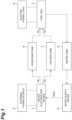
- the regenerative fuel cell system includes a water electrolysis device 1 and an external power source 2 connected to the water electrolysis device 1.
- the water electrolysis device 1 electrolyzes water supplied from a water supply device 5 due to energization from the external power source 2 and generates hydrogen and oxygen.
- the regenerative fuel cell system includes a fuel cell 3 and an electric power load 4 connected to the fuel cell 3.
- the fuel cell 3 generates electric power using hydrogen stored in a hydrogen tank 6 and oxygen stored in an oxygen tank 7 as raw materials.
- the fuel cell 3 is, for example, a polymer electrolyte fuel cell (PEFC).
- PEFC polymer electrolyte fuel cell
- the regenerative fuel cell system While the stored fuel is enabled, electric power is generated by the fuel cell 3, and water is generated and stored in a water tank 8. After the fuel is consumed, the water stored in the water tank 8 is electrolyzed into hydrogen and oxygen in the water electrolysis device 1 using the external power source 2. The generated hydrogen and oxygen are stored in the hydrogen tank 6 and the oxygen tank 7 at a predetermined pressure and are supplied again to the fuel cell 3 to generate electric power.
- the regenerative fuel cell system has a high energy density and has a weight which is one-half to one-third that of other secondary batteries such as lithium ion batteries. In this way, the regenerative fuel cell system is light in weight and thus is advantageous for mounting in a moving body.
- the hydrogen-oxygen reaction device according to the embodiment is provided in a subsequent stage of the water electrolysis device 1 in the regenerative fuel cell system.
- FIG. 2 respective devices provided between the water electrolysis device 1 and the hydrogen tank 6 and the oxygen tank 7 located at the subsequent stage thereof will be described.
- the water electrolysis device 1 hydrogen and oxygen are separated and collected, but a gas collected as a hydrogen gas from the water electrolysis device 1 is not a pure hydrogen gas but a mixed gas including water vapor derived from water included in the water electrolysis device 1 and some of oxygen generated in the water electrolysis device 1.
- a gas-liquid separation device 11 which removes a water vapor component from a mixed gas having hydrogen from the water electrolysis device 1 as a main component
- a hydrogen-oxygen reaction device 20 (20A) which removes the oxygen component by allowing the oxygen component to react with hydrogen and producing water are provided between the water electrolysis device 1 and the hydrogen tank 6.
- a gas collected as oxygen gas from the water electrolysis device 1 includes not only oxygen but also water vapor derived from water included in the water electrolysis device 1 and some of hydrogen generated in the water electrolysis device 1. Therefore, a gas-liquid separation device 12 which removes the water vapor component from a mixed gas having oxygen from the water electrolysis device 1 as a main component, and a hydrogen-oxygen reaction device 20 (20B) which removes the oxygen component by allowing the oxygen component to react with hydrogen and producing water are provided between the water electrolysis device 1 and the oxygen tank 7.
- the water vapor (water) removed in the gas-liquid separation devices 11 and 12 and the water removed in the hydrogen-oxygen reaction devices 20A and 20B are returned to the water electrolysis device 1 and used for generating hydrogen and oxygen.
- the hydrogen-oxygen reaction device 20 is a device which is provided in the subsequent stage of the water electrolysis device 1 and removes a gas that is not a main component from a hydrogen-oxygen mixed gas having hydrogen or oxygen as the main component.
- the gas having a component to be removed is oxygen in the case of a mixed gas having hydrogen as the main component and is hydrogen in the case of a mixed gas having oxygen as the main component.
- the hydrogen-oxygen reaction devices 20A and 20B have the same structure, the hydrogen-oxygen reaction device 20 will be described in the following embodiment.
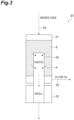
- the hydrogen-oxygen reaction device 20 includes a reaction vessel 21 including a reaction region S filled with a reaction catalyst for hydrogen and oxygen, a water vapor pipe 22 inserted into the reaction vessel 21, a cooling portion 23 which cools the water vapor pipe 22, an introduction portion 24 which introduces a hydrogen-oxygen mixed gas having one of hydrogen and oxygen as a main component into the reaction vessel 21, and a discharge portion 25 which discharges the gas that has passed through the reaction region S.
- the reaction region S in the reaction vessel 21 of the hydrogen-oxygen reaction device 20 is formed by a reaction catalyst which promotes a reaction between hydrogen and oxygen being filled thereinto.
- the reaction catalyst is not particularly limited as long as it is a catalyst related to the reaction between hydrogen and oxygen.
- platinum (Pt) can be used.
- the introduction portion 24 is mounted on an upper portion of the reaction vessel 21 and has a function of introducing the mixed gas (the hydrogen-oxygen mixed gas having one of hydrogen and oxygen as the main component) from the gas-liquid separation device (the gas-liquid separation device 11 or the gas-liquid separation device 12) into the reaction vessel 21.
- the discharge portion 25 is mounted on a lower portion of the reaction vessel 21 and has a function of discharging a gas in the reaction vessel 21 to the outside.
- the gas discharged from the discharge portion 25 is transported to a tank (the hydrogen tank 6 or the oxygen tank 7) located at a subsequent stage.
- the water vapor pipe 22 is a pipe which passes through the reaction vessel 21 from below the reaction vessel 21 and is partially inserted into the reaction region S in the reaction vessel 21. One end portion of the water vapor pipe 22 is provided in the reaction region S. At least a part of a region of the water vapor pipe 22 which is in contact with the reaction region S is formed by a water vapor permeable membrane.
- the water vapor permeable membrane is a membrane which (almost) does not allow permeation of hydrogen and oxygen that are components of the mixed gas and can selectively allow permeation of water vapor. Examples of such a membrane include a moisture control tube (manufactured by SMC) and a Nafion membrane but are not limited thereto.
- one water vapor pipe 22 is inserted into the reaction vessel 21, but a plurality of water vapor pipes 22 may be provided.
- the water vapor generated in the reaction region S can be discharged to the outside by the water vapor pipe 22 having the water vapor permeable membrane inserted into the reaction region S and the cooling portion 23. Therefore, the reaction efficiency between hydrogen and oxygen using the reaction catalyst in the reaction region S is improved.
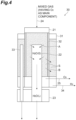
- the hydrogen-oxygen reaction device 30 shown in FIG. 4 is different from the hydrogen-oxygen reaction device 20 shown in FIG. 3 in the following points. That is, in the hydrogen-oxygen reaction device 30, a second reaction vessel 31 is provided to surround the periphery of the reaction vessel 21. Additionally, the reaction vessel 21 and the second reaction vessel 31 are partitioned by a hydrogen selective permeable membrane 32.
- the periphery of the reaction region S of the reaction vessel 21 is configured of the hydrogen selective permeable membrane 32.
- the hydrogen selective permeable membrane 32 has a function of selectively transmitting hydrogen of hydrogen and oxygen.
- the hydrogen selective permeable membrane 32 may have oxygen permeability. That is, the hydrogen selective permeable membrane 32 is a membrane having a higher hydrogen permeability than oxygen permeability.
- a membrane having a larger difference between the oxygen permeability and the hydrogen permeability can be appropriately used as the hydrogen selective permeable membrane 32.
- a reaction region S (a second reaction region) is formed by the reaction catalyst.
- a water vapor pipe 33 (a second water vapor pipe) having a water vapor permeable membrane is also inserted into the second reaction vessel 31.
- the water vapor pipe 22 at least a part of the region in contact with the reaction region S is formed by the water vapor permeable membrane.
- the number of the water vapor pipes 33 inserted into the second reaction vessel 31 can be changed as appropriate, as in the water vapor pipe 22.
- the cooling portion 23 of the hydrogen-oxygen reaction device 30 cools both the water vapor pipe 22 from the reaction vessel 21 and the water vapor pipe 33 from the second reaction vessel 31.
- a discharge portion 34 (a second discharge portion) is also mounted on a lower portion of the second reaction vessel 31.
- the discharge portion 34 has a function of discharging a gas in the second reaction vessel 31 to the outside. The gas discharged from the discharge portion 34 is transported to a tank located at a subsequent stage.
- the cooling portion 23 may be provided individually for each of the water vapor pipes 22 and 31.
- the hydrogen-oxygen reaction device 30 is appropriately used for removing hydrogen from the hydrogen-oxygen mixed gas having oxygen as the main component.
- the mixed gas having oxygen as the main component is introduced into the reaction vessel 21 from the introduction portion 24.
- the mixed gas introduced into the reaction vessel 21 moves downward through the reaction region S filled with the reaction catalyst.
- hydrogen and oxygen in the mixed gas react with each other due to the action of the reaction catalyst, and thus water vapor is formed.
- the water vapor generated in the reaction region S passes through the water vapor permeable membrane of the water vapor pipe 22 and moves into the water vapor pipe 22 as indicated by an arrow A in FIG. 4 .
- the gas here, oxygen
- the ratio of the main component is increased (the purity is increased) is discharged from the discharge portion 25 to the outside of the reaction vessel 21.
- the gas here, hydrogen
- the discharge portion 34 is discharged from the discharge portion 34 to the outside of the second reaction vessel 31 in a state in which the proportion of the main component is increased (the purity is increased).
- the water vapor introduced into the water vapor pipes 22 and 33 is cooled and liquefied by the cooling portion 23 and then discharged from the hydrogen-oxygen reaction device 30 to the outside. Since the liquefied water vapor is discharged to the outside and thus a proportion of the water vapor in the water vapor pipes 22 and 33 is reduced, the water vapor generated again in the reaction vessel 21 and the second reaction vessel 31 is introduced into the water vapor pipes 22 and 33 through the water vapor permeable membrane. As described above, since the water vapor pipes 22 and 33 are inserted into both the reaction vessel 21 and the second reaction vessel 31, the water vapor moves into the water vapor pipes 22 and 33 through the water vapor permeable membrane. Therefore, the retention of the water vapor in the reaction vessel 21 and the second reaction vessel 31 can be suppressed.
- the second reaction vessel 31 in which the gas in the reaction vessel 21 can move is provided, and the hydrogen selective permeable membrane 32 is provided between the reaction vessel 21 and the second reaction vessel 31. Therefore, the hydrogen component in the reaction vessel 21 moves to the second reaction vessel 31. Then in the reaction vessel 21, the proportion of the oxygen component is increased compared with the introduced mixed gas. When the hydrogen-oxygen mixed gas having oxygen as the main component is introduced into the reaction vessel 21, the proportion of the main component is increased. When the water vapor is formed by the reaction between hydrogen and oxygen due to the reaction catalyst in the reaction region S in a state in which the proportion of the oxygen component is increased in this way, hydrogen is effectively removed from the gas discharged from the discharge portion 25.
- the gas in which the proportion of the oxygen component is further increased is discharged from the discharge portion 25.
- the hydrogen-oxygen reaction device 30 when the hydrogen-oxygen mixed gas having oxygen as the main component is introduced into the reaction vessel 21, the purity of oxygen in the gas discharged from the lower discharge portion 25 is further increased as compared with the hydrogen-oxygen reaction device 20.
- a hydrogen selective permeable membrane 32 is provided at a boundary between the reaction vessel 21 and the second reaction vessel 31 to increase the purity of oxygen discharged from the discharge portion 25 when the hydrogen-oxygen mixed gas having oxygen as the main component is introduced. Additionally, a configuration in which hydrogen is preferentially moved with respect to the second reaction vessel 31 is adopted. However, when a permeable membrane which can selectively allow oxygen to permeate therethrough is mounted instead of the hydrogen selective permeable membrane 32, a configuration opposite to the above can be realized.
- the permeable membrane which can selectively allow oxygen to permeate therethrough is provided between the reaction vessel 21 and the second reaction vessel 31 to increase a purity of hydrogen discharged from the discharge portion 25 when the hydrogen-oxygen mixed gas having hydrogen as the main component is introduced.
- the permeable membrane which can selectively allow oxygen to permeate therethrough is provided between the reaction vessel 21 and the second reaction vessel 31 to increase a purity of hydrogen discharged from the discharge portion 25 when the hydrogen-oxygen mixed gas having hydrogen as the main component is introduced.
- the reaction vessel 21 and the second reaction vessel 31 may be connected to each other via the hydrogen selective permeable membrane 32, and a positional relationship between the reaction vessel 21 and the second reaction vessel 31 is not particularly limited.
- a configuration in which the reaction vessel 21 and the second reaction vessel 31 are disposed adjacent to each other may be adopted.
- shapes of the reaction vessel 21 and the second reaction vessel 31 may be appropriately changed.
- the hydrogen selective permeable membrane 32 does not need to be provided on the entire surface around the reaction region S in the reaction vessel 21.
- the hydrogen selective permeable membrane 32 has a function of selecting and separating hydrogen from the mixed gas introduced into the reaction vessel 21. Therefore, the hydrogen selective permeable membrane 32 can appropriately perform separation of hydrogen when it is provided closer to the introduction portion 24 than to the discharge portion 25 is, and thus the purity of oxygen discharged from the discharge portion 25 can be appropriately increased.
- the present disclosure is not limited to the above-described embodiments, and various changes can be made.
- the arrangement of the introduction portion 24 and the discharge portion 25 with respect to the reaction vessel 21 is not particularly limited.
- the introduction portion 24 is provided at one end portion of the reaction region S and the discharge portion 25 is provided at the other end portion on the side opposite to the one end portion of the reaction region S, the gas which has passed through the reaction region S can be discharged from the discharge portion 25, and thus the gas of which a purity is increased by the formation of the water vapor can be discharged from the discharge portion 25.
- the shapes of the water vapor pipes 22 and 33 can be changed as appropriate.
- the shape of the water vapor pipe may be changed to increase an area facing the reaction region in the water vapor permeable membrane provided in the water vapor pipe 22.
- the hydrogen-oxygen reaction devices 20 and 30 may be used for an application different from the separation of hydrogen and oxygen in the subsequent stage of the water electrolysis device in the above-described regenerative fuel cell system.
- gases which are components different from a main component can be appropriately removed from a hydrogen-oxygen mixed gas having hydrogen or oxygen as the main component.
Landscapes
- Chemical & Material Sciences (AREA)
- Organic Chemistry (AREA)
- Inorganic Chemistry (AREA)
- Engineering & Computer Science (AREA)
- Chemical Kinetics & Catalysis (AREA)
- Electrochemistry (AREA)
- Metallurgy (AREA)
- Materials Engineering (AREA)
- General Chemical & Material Sciences (AREA)
- Analytical Chemistry (AREA)
- Life Sciences & Earth Sciences (AREA)
- Sustainable Energy (AREA)
- Combustion & Propulsion (AREA)
- Sustainable Development (AREA)
- Manufacturing & Machinery (AREA)
- Fuel Cell (AREA)
- Oxygen, Ozone, And Oxides In General (AREA)
- Hydrogen, Water And Hydrids (AREA)
- Separation Using Semi-Permeable Membranes (AREA)
Claims (10)
- Wasserstoff Sauerstoff-Reaktionsvorrichtung (20), umfassend:ein Reaktionsgefäß (21), das einen Reaktionsbereich (S) enthält, der mit einem Reaktionskatalysator gefüllt ist, der konfiguriert ist, um eine Reaktion zwischen Wasserstoff und Sauerstoff zu fördern;einen Einleitungsabschnitt (24), der konfiguriert ist, um ein Wasserstoff Sauerstoff-Mischgas, das Wasserstoff oder Sauerstoff als eine Hauptkomponente aufweist, in das Reaktionsgefäß (21) einzuleiten;ein Wasserdampfrohr (22), von dem ein Endabschnitt in das Reaktionsgefäß (21) eingeführt ist und einen Bereich enthält, der mit dem Reaktionsbereich (S) in Kontakt steht, wobei mindestens ein Teil des Bereichs, der mit dem Reaktionsbereich (S) in Kontakt steht, aus einer wasserdampfdurchlässigen Membran gebildet ist;einen Abgabeabschnitt (25), der konfiguriert ist, um ein Gas in dem Reaktionsgefäß (21) durch den Abgabeabschnitt nach außen abzugeben; undeinen Kühlabschnitt (23), der konfiguriert ist, um das Wasserdampfrohr (22) außerhalb des Reaktionsgefäßes (21) zu kühlen.
- Wasserstoff-Sauerstoff-Reaktionsvorrichtung (20) nach Anspruch 1, wobei
der Einleitungsabschnitt (24) an einem Endabschnitt des Reaktionsbereichs (S) bereitgestellt ist und der Abgabeabschnitt (25) an dem anderen Endabschnitt auf einer Seite gegenüber dem einen Endabschnitt des Reaktionsbereichs (S) bereitgestellt ist. - Wasserstoff-Sauerstoff-Reaktionsvorrichtung (20) nach Anspruch 1, wobei
eine Vielzahl von Wasserdampfrohren (22) in das Reaktionsgefäß (21) eingeführt ist. - Wasserstoff-Sauerstoff-Reaktionsvorrichtung (20) nach Anspruch 2, wobei
eine Vielzahl von Wasserdampfrohren (22) in das Reaktionsgefäß (21) eingeführt ist. - Wasserstoff-Sauerstoff-Reaktionsvorrichtung (20) nach Anspruch 1, ferner umfassend:ein zweites Reaktionsgefäß (31), das einen zweiten Reaktionsbereich (S) aufweist, der mit dem Reaktionskatalysator gefüllt ist;eine wasserstoffselektive durchlässige Membran (32), die an einer Grenze zwischen dem Reaktionsgefäß (21) und dem zweiten Reaktionsgefäß (31) bereitgestellt ist;ein zweites Wasserdampfrohr (33), von dem ein Endabschnitt in das zweite Reaktionsgefäß (31) eingeführt ist und das einen Bereich enthält, der mit dem zweiten Reaktionsbereich (S) in Kontakt steht, wobei mindestens ein Teil des Bereichs, der mit dem zweiten Reaktionsbereich (S) in Kontakt steht, aus einer wasserdampfdurchlässigen Membran gebildet ist; undeinen zweiten Abgabeabschnitt (34), der konfiguriert ist, um ein Gas in dem zweiten Reaktionsgefäß (31) nach außen abzugeben,wobei der Kühlabschnitt (23) konfiguriert ist, um das zweite Wasserdampfrohr (33) außerhalb des zweiten Reaktionsgefäßes (31) zu kühlen.
- Wasserstoff-Sauerstoff-Reaktionsvorrichtung (20) nach Anspruch 2, ferner umfassend:ein zweites Reaktionsgefäß (31), das einen zweiten Reaktionsbereich (S) aufweist, der mit dem Reaktionskatalysator gefüllt ist;eine wasserstoffselektive durchlässige Membran (32), die an einer Grenze zwischen dem Reaktionsgefäß (21) und dem zweiten Reaktionsgefäß (31) bereitgestellt ist;ein zweites Wasserdampfrohr (33), von dem ein Endabschnitt in das zweite Reaktionsgefäß (31) eingeführt ist und das einen Bereich enthält, der mit dem zweiten Reaktionsbereich (S) in Kontakt steht, wobei mindestens ein Teil des Bereichs, der mit dem zweiten Reaktionsbereich (S) in Kontakt steht, aus einer wasserdampfdurchlässigen Membran gebildet ist; undeinen zweiten Abgabeabschnitt (34), der konfiguriert ist, um ein Gas in dem zweiten Reaktionsgefäß (31) nach außen abzugeben,wobei der Kühlabschnitt (23) konfiguriert ist, um das zweite Wasserdampfrohr (33) außerhalb des zweiten Reaktionsgefäßes (31) zu kühlen.
- Wasserstoff Sauerstoff-Reaktionsvorrichtung (20) nach Anspruch 3, ferner umfassend:ein zweites Reaktionsgefäß (31), das einen zweiten Reaktionsbereich (S) aufweist, der mit dem Reaktionskatalysator gefüllt ist;eine wasserstoffselektive durchlässige Membran (32), die an einer Grenze zwischen dem Reaktionsgefäß (21) und dem zweiten Reaktionsgefäß (31) bereitgestellt ist;ein zweites Wasserdampfrohr (33), von dem ein Endabschnitt in das zweite Reaktionsgefäß (31) eingeführt ist und das einen Bereich enthält, der mit dem zweiten Reaktionsbereich (S) in Kontakt steht, wobei mindestens ein Teil des Bereichs, der mit dem zweiten Reaktionsbereich (S) in Kontakt steht, aus einer
wasserdampfdurchlässigen Membran gebildet ist; undeinen zweiten Abgabeabschnitt (34), der konfiguriert ist, um ein Gas in dem zweiten Reaktionsgefäß (31) nach außen abzugeben,wobei der Kühlabschnitt (23) konfiguriert ist, um das zweite Wasserdampfrohr (33) außerhalb des zweiten Reaktionsgefäßes (31) zu kühlen. - Wasserstoff-Sauerstoff-Reaktionsvorrichtung (20) nach Anspruch 4, ferner umfassend:ein zweites Reaktionsgefäß (31), das einen zweiten Reaktionsbereich (S) aufweist, der mit dem Reaktionskatalysator gefüllt ist;eine wasserstoffselektive durchlässige Membran (32), die an einer Grenze zwischen dem Reaktionsgefäß (21) und dem zweiten Reaktionsgefäß (31) bereitgestellt ist;ein zweites Wasserdampfrohr (33), von dem ein Endabschnitt in das zweite Reaktionsgefäß (31) eingeführt ist und das einen Bereich enthält, der mit dem zweiten Reaktionsbereich (S) in Kontakt steht, wobei mindestens ein Teil des Bereichs, der mit dem zweiten Reaktionsbereich (S) in Kontakt steht, aus einer wasserdampfdurchlässigen Membran gebildet ist; undeinen zweiten Abgabeabschnitt (34), der konfiguriert ist, um ein Gas in dem zweiten Reaktionsgefäß (31) nach außen abzugeben,wobei der Kühlabschnitt (23) konfiguriert ist, um das zweite Wasserdampfrohr (33) außerhalb des zweiten Reaktionsgefäßes (31) zu kühlen.
- Regeneratives Brennstoffzellensystem, umfassend die Wasserstoff-Sauerstoff-Reaktionsvorrichtung (20) nach einem der Ansprüche 1 bis 8.
- Flugzeug, in dem das regenerative Brennstoffzellensystem nach Anspruch 9 montiert ist.
Applications Claiming Priority (2)
| Application Number | Priority Date | Filing Date | Title |
|---|---|---|---|
| JP2017131199 | 2017-07-04 | ||
| PCT/JP2018/000313 WO2019008799A1 (ja) | 2017-07-04 | 2018-01-10 | 水素酸素反応装置 |
Publications (3)
| Publication Number | Publication Date |
|---|---|
| EP3650407A1 EP3650407A1 (de) | 2020-05-13 |
| EP3650407A4 EP3650407A4 (de) | 2021-04-07 |
| EP3650407B1 true EP3650407B1 (de) | 2024-12-25 |
Family
ID=64949901
Family Applications (1)
| Application Number | Title | Priority Date | Filing Date |
|---|---|---|---|
| EP18827994.7A Active EP3650407B1 (de) | 2017-07-04 | 2018-01-10 | Wasserstoffsauerstoffreaktionsvorrichtung |
Country Status (4)
| Country | Link |
|---|---|
| US (1) | US10801116B2 (de) |
| EP (1) | EP3650407B1 (de) |
| JP (1) | JP6828819B2 (de) |
| WO (1) | WO2019008799A1 (de) |
Families Citing this family (2)
| Publication number | Priority date | Publication date | Assignee | Title |
|---|---|---|---|---|
| US11866182B2 (en) * | 2020-05-01 | 2024-01-09 | General Electric Company | Fuel delivery system having a fuel oxygen reduction unit |
| GB2608805A (en) * | 2021-07-09 | 2023-01-18 | Enapter S R L | Gas block |
Family Cites Families (16)
| Publication number | Priority date | Publication date | Assignee | Title |
|---|---|---|---|---|
| CH90085A (fr) * | 1920-02-12 | 1921-07-16 | Air Liquide | Procédé pour purifier un mélange gazeux contenant de l'hydrogène et de l'oxygène, et où l'un de ces gaz constitue une impureté par rapport à l'autre, et dispositif pour sa mise en oeuvre. |
| IE54140B1 (en) | 1982-03-19 | 1989-06-21 | Johnson Matthey Plc | Deoxygenation process |
| CA1198710A (en) * | 1983-10-24 | 1985-12-31 | Karl T. Chuang | Oxygen generator |
| JP2706320B2 (ja) | 1989-07-07 | 1998-01-28 | 三菱重工業株式会社 | 水電解装置 |
| JP3639440B2 (ja) * | 1998-09-02 | 2005-04-20 | 忠弘 大見 | 水分発生用反応炉 |
| JP2001146404A (ja) | 1999-11-16 | 2001-05-29 | Daikin Ind Ltd | 水素ガス生成装置 |
| JP3604620B2 (ja) * | 2000-08-03 | 2004-12-22 | 株式会社神鋼環境ソリューション | 水電解生成ガス純化システム及び純化方法 |
| JP4290454B2 (ja) | 2003-03-28 | 2009-07-08 | 三井化学株式会社 | ガス拡散電極の製造方法、電解槽及び電解方法 |
| JP2006004787A (ja) | 2004-06-18 | 2006-01-05 | Nitto Denko Corp | 固体高分子電解質型燃料電池用ガス拡散膜 |
| JP2007153670A (ja) | 2005-12-05 | 2007-06-21 | Mitsubishi Kakoki Kaisha Ltd | 還元ガス製造装置及び製造方法 |
| JP2009143732A (ja) | 2007-12-11 | 2009-07-02 | Dainippon Printing Co Ltd | 水素製造装置および燃料電池 |
| CN101407920B (zh) * | 2008-10-31 | 2010-12-08 | 西南化工研究设计院 | 一种由水电解连续生产高纯氢的工艺 |
| JP5301265B2 (ja) | 2008-12-25 | 2013-09-25 | 石油資源開発株式会社 | 酸素生成装置と水素生成装置とを備える燃料電池システム |
| WO2011077969A1 (ja) * | 2009-12-24 | 2011-06-30 | コニカミノルタホールディングス株式会社 | 反応容器及びそれを用いた燃料電池システム |
| EP2772976B1 (de) * | 2013-02-27 | 2017-11-15 | Airbus Defence and Space GmbH | Regeneratives Brennstoffzellensystem mit Gasreinigung |
| JP2015116545A (ja) * | 2013-12-19 | 2015-06-25 | 日立Geニュークリア・エナジー株式会社 | 水素ガス処理装置 |
-
2018
- 2018-01-10 JP JP2019528337A patent/JP6828819B2/ja active Active
- 2018-01-10 US US16/628,087 patent/US10801116B2/en active Active
- 2018-01-10 EP EP18827994.7A patent/EP3650407B1/de active Active
- 2018-01-10 WO PCT/JP2018/000313 patent/WO2019008799A1/ja not_active Ceased
Also Published As
| Publication number | Publication date |
|---|---|
| JP6828819B2 (ja) | 2021-02-10 |
| EP3650407A4 (de) | 2021-04-07 |
| WO2019008799A1 (ja) | 2019-01-10 |
| US10801116B2 (en) | 2020-10-13 |
| EP3650407A1 (de) | 2020-05-13 |
| US20200173035A1 (en) | 2020-06-04 |
| JPWO2019008799A1 (ja) | 2020-05-21 |
Similar Documents
| Publication | Publication Date | Title |
|---|---|---|
| US9631285B2 (en) | Electrochemical process for the production of synthesis gas using atmospheric air and water | |
| US11456472B2 (en) | Method and device for generating electric energy | |
| US9979040B2 (en) | Redox device | |
| CN114585773B (zh) | 用于还原二氧化碳的电解装置和方法 | |
| US9828681B2 (en) | Redox device | |
| CN111727273A (zh) | 一氧化碳和/或合成气的电化学制取 | |
| AU2018302325A1 (en) | CO2 electrolyser | |
| EP3650407B1 (de) | Wasserstoffsauerstoffreaktionsvorrichtung | |
| US7056610B2 (en) | Alkaline direct methanol fuel cell | |
| KR102895931B1 (ko) | 전해 셀 및 이를 포함하는 암모니아 전해 시스템 | |
| JP6804848B2 (ja) | アンモニア分解方法 | |
| KR102814003B1 (ko) | 연료전지 시스템 | |
| JP2023085880A (ja) | 二酸化炭素処理装置 | |
| KR20230065803A (ko) | 수소 공급 시스템 | |
| KR20220079511A (ko) | 일산화탄소-풍부 가스 생성물을 생성하기 위한 방법 및 플랜트 | |
| JP2011208182A (ja) | 二酸化硫黄ガスを燃料とする発電・水素製造装置 | |
| EP4410404A1 (de) | Ammoniakelektrolysesystem und steuerungsverfahren dafür | |
| CN116613359B (zh) | 发电装置及发电系统 | |
| KR20250077260A (ko) | 상온 상압에서 암모니아를 액화시키는 방법과 이를 이용하여 고순도 수소를 생산하기 위한 암모니아 전기분해 장치 | |
| KR20260015070A (ko) | 다-단 전기분해용 장치 및 방법 | |
| KR20250100495A (ko) | 미반응 암모니아 제거 장치가 구비된 수소 생산 시스템 | |
| IT201900009708A1 (it) | Dispositivo per la produzione di idrogeno e energia elettrica tramite reazioni di ossidoriduzione spontanee sia da comparto anodico che catodico con elettrolita acquoso. | |
| JP6191003B1 (ja) | 高純度窒素ガス生成システム | |
| GB2461390A (en) | Composite Electrochemical Cell | |
| JP2016004643A (ja) | 燃料電池システム |
Legal Events
| Date | Code | Title | Description |
|---|---|---|---|
| STAA | Information on the status of an ep patent application or granted ep patent |
Free format text: STATUS: THE INTERNATIONAL PUBLICATION HAS BEEN MADE |
|
| PUAI | Public reference made under article 153(3) epc to a published international application that has entered the european phase |
Free format text: ORIGINAL CODE: 0009012 |
|
| STAA | Information on the status of an ep patent application or granted ep patent |
Free format text: STATUS: REQUEST FOR EXAMINATION WAS MADE |
|
| 17P | Request for examination filed |
Effective date: 20200204 |
|
| AK | Designated contracting states |
Kind code of ref document: A1 Designated state(s): AL AT BE BG CH CY CZ DE DK EE ES FI FR GB GR HR HU IE IS IT LI LT LU LV MC MK MT NL NO PL PT RO RS SE SI SK SM TR |
|
| AX | Request for extension of the european patent |
Extension state: BA ME |
|
| DAV | Request for validation of the european patent (deleted) | ||
| DAX | Request for extension of the european patent (deleted) | ||
| A4 | Supplementary search report drawn up and despatched |
Effective date: 20210304 |
|
| RIC1 | Information provided on ipc code assigned before grant |
Ipc: H01M 8/00 20160101ALI20210226BHEP Ipc: C01B 3/00 20060101ALI20210226BHEP Ipc: C01B 13/02 20060101ALI20210226BHEP Ipc: C01B 5/00 20060101ALI20210226BHEP Ipc: H01M 8/10 20160101ALI20210226BHEP Ipc: C25B 15/08 20060101ALI20210226BHEP Ipc: C25B 1/04 20210101AFI20210226BHEP Ipc: H01M 8/0662 20160101ALI20210226BHEP Ipc: H01M 8/06 20160101ALI20210226BHEP Ipc: C01B 3/50 20060101ALI20210226BHEP |
|
| STAA | Information on the status of an ep patent application or granted ep patent |
Free format text: STATUS: EXAMINATION IS IN PROGRESS |
|
| 17Q | First examination report despatched |
Effective date: 20220207 |
|
| REG | Reference to a national code |
Ref country code: DE Ref legal event code: R079 Free format text: PREVIOUS MAIN CLASS: C01B0005000000 Ipc: C25B0001040000 Ref country code: DE Ref legal event code: R079 Ref document number: 602018077982 Country of ref document: DE Free format text: PREVIOUS MAIN CLASS: C01B0005000000 Ipc: C25B0001040000 |
|
| GRAP | Despatch of communication of intention to grant a patent |
Free format text: ORIGINAL CODE: EPIDOSNIGR1 |
|
| STAA | Information on the status of an ep patent application or granted ep patent |
Free format text: STATUS: GRANT OF PATENT IS INTENDED |
|
| RIC1 | Information provided on ipc code assigned before grant |
Ipc: B01D 53/00 20060101ALI20240725BHEP Ipc: H01M 8/18 20060101ALI20240725BHEP Ipc: C01B 13/02 20060101ALI20240725BHEP Ipc: C01B 5/00 20060101ALI20240725BHEP Ipc: C01B 3/50 20060101ALI20240725BHEP Ipc: C25B 15/08 20060101ALI20240725BHEP Ipc: C25B 1/04 20060101AFI20240725BHEP |
|
| INTG | Intention to grant announced |
Effective date: 20240809 |
|
| GRAS | Grant fee paid |
Free format text: ORIGINAL CODE: EPIDOSNIGR3 |
|
| GRAA | (expected) grant |
Free format text: ORIGINAL CODE: 0009210 |
|
| STAA | Information on the status of an ep patent application or granted ep patent |
Free format text: STATUS: THE PATENT HAS BEEN GRANTED |
|
| AK | Designated contracting states |
Kind code of ref document: B1 Designated state(s): AL AT BE BG CH CY CZ DE DK EE ES FI FR GB GR HR HU IE IS IT LI LT LU LV MC MK MT NL NO PL PT RO RS SE SI SK SM TR |
|
| REG | Reference to a national code |
Ref country code: GB Ref legal event code: FG4D |
|
| REG | Reference to a national code |
Ref country code: CH Ref legal event code: EP |
|
| REG | Reference to a national code |
Ref country code: DE Ref legal event code: R096 Ref document number: 602018077982 Country of ref document: DE |
|
| REG | Reference to a national code |
Ref country code: IE Ref legal event code: FG4D |
|
| REG | Reference to a national code |
Ref country code: LT Ref legal event code: MG9D |
|
| PG25 | Lapsed in a contracting state [announced via postgrant information from national office to epo] |
Ref country code: HR Free format text: LAPSE BECAUSE OF FAILURE TO SUBMIT A TRANSLATION OF THE DESCRIPTION OR TO PAY THE FEE WITHIN THE PRESCRIBED TIME-LIMIT Effective date: 20241225 |
|
| PGFP | Annual fee paid to national office [announced via postgrant information from national office to epo] |
Ref country code: DE Payment date: 20250131 Year of fee payment: 8 |
|
| PG25 | Lapsed in a contracting state [announced via postgrant information from national office to epo] |
Ref country code: FI Free format text: LAPSE BECAUSE OF FAILURE TO SUBMIT A TRANSLATION OF THE DESCRIPTION OR TO PAY THE FEE WITHIN THE PRESCRIBED TIME-LIMIT Effective date: 20241225 |
|
| PG25 | Lapsed in a contracting state [announced via postgrant information from national office to epo] |
Ref country code: BG Free format text: LAPSE BECAUSE OF FAILURE TO SUBMIT A TRANSLATION OF THE DESCRIPTION OR TO PAY THE FEE WITHIN THE PRESCRIBED TIME-LIMIT Effective date: 20241225 |
|
| PG25 | Lapsed in a contracting state [announced via postgrant information from national office to epo] |
Ref country code: NO Free format text: LAPSE BECAUSE OF FAILURE TO SUBMIT A TRANSLATION OF THE DESCRIPTION OR TO PAY THE FEE WITHIN THE PRESCRIBED TIME-LIMIT Effective date: 20250325 |
|
| PG25 | Lapsed in a contracting state [announced via postgrant information from national office to epo] |
Ref country code: LV Free format text: LAPSE BECAUSE OF FAILURE TO SUBMIT A TRANSLATION OF THE DESCRIPTION OR TO PAY THE FEE WITHIN THE PRESCRIBED TIME-LIMIT Effective date: 20241225 Ref country code: GR Free format text: LAPSE BECAUSE OF FAILURE TO SUBMIT A TRANSLATION OF THE DESCRIPTION OR TO PAY THE FEE WITHIN THE PRESCRIBED TIME-LIMIT Effective date: 20250326 |
|
| PG25 | Lapsed in a contracting state [announced via postgrant information from national office to epo] |
Ref country code: RS Free format text: LAPSE BECAUSE OF FAILURE TO SUBMIT A TRANSLATION OF THE DESCRIPTION OR TO PAY THE FEE WITHIN THE PRESCRIBED TIME-LIMIT Effective date: 20250325 |
|
| REG | Reference to a national code |
Ref country code: NL Ref legal event code: MP Effective date: 20241225 |
|
| PG25 | Lapsed in a contracting state [announced via postgrant information from national office to epo] |
Ref country code: NL Free format text: LAPSE BECAUSE OF FAILURE TO SUBMIT A TRANSLATION OF THE DESCRIPTION OR TO PAY THE FEE WITHIN THE PRESCRIBED TIME-LIMIT Effective date: 20241225 |
|
| REG | Reference to a national code |
Ref country code: AT Ref legal event code: MK05 Ref document number: 1754208 Country of ref document: AT Kind code of ref document: T Effective date: 20241225 |
|
| PG25 | Lapsed in a contracting state [announced via postgrant information from national office to epo] |
Ref country code: SM Free format text: LAPSE BECAUSE OF FAILURE TO SUBMIT A TRANSLATION OF THE DESCRIPTION OR TO PAY THE FEE WITHIN THE PRESCRIBED TIME-LIMIT Effective date: 20241225 |
|
| PG25 | Lapsed in a contracting state [announced via postgrant information from national office to epo] |
Ref country code: PL Free format text: LAPSE BECAUSE OF FAILURE TO SUBMIT A TRANSLATION OF THE DESCRIPTION OR TO PAY THE FEE WITHIN THE PRESCRIBED TIME-LIMIT Effective date: 20241225 |
|
| PG25 | Lapsed in a contracting state [announced via postgrant information from national office to epo] |
Ref country code: ES Free format text: LAPSE BECAUSE OF FAILURE TO SUBMIT A TRANSLATION OF THE DESCRIPTION OR TO PAY THE FEE WITHIN THE PRESCRIBED TIME-LIMIT Effective date: 20241225 |
|
| PG25 | Lapsed in a contracting state [announced via postgrant information from national office to epo] |
Ref country code: IS Free format text: LAPSE BECAUSE OF FAILURE TO SUBMIT A TRANSLATION OF THE DESCRIPTION OR TO PAY THE FEE WITHIN THE PRESCRIBED TIME-LIMIT Effective date: 20250425 |
|
| PG25 | Lapsed in a contracting state [announced via postgrant information from national office to epo] |
Ref country code: PT Free format text: LAPSE BECAUSE OF FAILURE TO SUBMIT A TRANSLATION OF THE DESCRIPTION OR TO PAY THE FEE WITHIN THE PRESCRIBED TIME-LIMIT Effective date: 20250428 |
|
| PG25 | Lapsed in a contracting state [announced via postgrant information from national office to epo] |
Ref country code: EE Free format text: LAPSE BECAUSE OF FAILURE TO SUBMIT A TRANSLATION OF THE DESCRIPTION OR TO PAY THE FEE WITHIN THE PRESCRIBED TIME-LIMIT Effective date: 20241225 |
|
| PG25 | Lapsed in a contracting state [announced via postgrant information from national office to epo] |
Ref country code: RO Free format text: LAPSE BECAUSE OF FAILURE TO SUBMIT A TRANSLATION OF THE DESCRIPTION OR TO PAY THE FEE WITHIN THE PRESCRIBED TIME-LIMIT Effective date: 20241225 Ref country code: AT Free format text: LAPSE BECAUSE OF FAILURE TO SUBMIT A TRANSLATION OF THE DESCRIPTION OR TO PAY THE FEE WITHIN THE PRESCRIBED TIME-LIMIT Effective date: 20241225 |
|
| PG25 | Lapsed in a contracting state [announced via postgrant information from national office to epo] |
Ref country code: SK Free format text: LAPSE BECAUSE OF FAILURE TO SUBMIT A TRANSLATION OF THE DESCRIPTION OR TO PAY THE FEE WITHIN THE PRESCRIBED TIME-LIMIT Effective date: 20241225 |
|
| PG25 | Lapsed in a contracting state [announced via postgrant information from national office to epo] |
Ref country code: CZ Free format text: LAPSE BECAUSE OF FAILURE TO SUBMIT A TRANSLATION OF THE DESCRIPTION OR TO PAY THE FEE WITHIN THE PRESCRIBED TIME-LIMIT Effective date: 20241225 |
|
| PG25 | Lapsed in a contracting state [announced via postgrant information from national office to epo] |
Ref country code: IT Free format text: LAPSE BECAUSE OF FAILURE TO SUBMIT A TRANSLATION OF THE DESCRIPTION OR TO PAY THE FEE WITHIN THE PRESCRIBED TIME-LIMIT Effective date: 20241225 |
|
| REG | Reference to a national code |
Ref country code: CH Ref legal event code: PL |
|
| PG25 | Lapsed in a contracting state [announced via postgrant information from national office to epo] |
Ref country code: SE Free format text: LAPSE BECAUSE OF FAILURE TO SUBMIT A TRANSLATION OF THE DESCRIPTION OR TO PAY THE FEE WITHIN THE PRESCRIBED TIME-LIMIT Effective date: 20241225 |
|
| PG25 | Lapsed in a contracting state [announced via postgrant information from national office to epo] |
Ref country code: MC Free format text: LAPSE BECAUSE OF FAILURE TO SUBMIT A TRANSLATION OF THE DESCRIPTION OR TO PAY THE FEE WITHIN THE PRESCRIBED TIME-LIMIT Effective date: 20241225 Ref country code: LU Free format text: LAPSE BECAUSE OF NON-PAYMENT OF DUE FEES Effective date: 20250110 |
|
| REG | Reference to a national code |
Ref country code: DE Ref legal event code: R097 Ref document number: 602018077982 Country of ref document: DE |
|
| PG25 | Lapsed in a contracting state [announced via postgrant information from national office to epo] |
Ref country code: DK Free format text: LAPSE BECAUSE OF FAILURE TO SUBMIT A TRANSLATION OF THE DESCRIPTION OR TO PAY THE FEE WITHIN THE PRESCRIBED TIME-LIMIT Effective date: 20241225 |
|
| PG25 | Lapsed in a contracting state [announced via postgrant information from national office to epo] |
Ref country code: BE Free format text: LAPSE BECAUSE OF NON-PAYMENT OF DUE FEES Effective date: 20250131 |
|
| PG25 | Lapsed in a contracting state [announced via postgrant information from national office to epo] |
Ref country code: CH Free format text: LAPSE BECAUSE OF NON-PAYMENT OF DUE FEES Effective date: 20250131 |
|
| REG | Reference to a national code |
Ref country code: BE Ref legal event code: MM Effective date: 20250131 |
|
| PLBE | No opposition filed within time limit |
Free format text: ORIGINAL CODE: 0009261 |
|
| STAA | Information on the status of an ep patent application or granted ep patent |
Free format text: STATUS: NO OPPOSITION FILED WITHIN TIME LIMIT |
|
| GBPC | Gb: european patent ceased through non-payment of renewal fee |
Effective date: 20250325 |
|
| 26N | No opposition filed |
Effective date: 20250926 |
|
| PG25 | Lapsed in a contracting state [announced via postgrant information from national office to epo] |
Ref country code: GB Free format text: LAPSE BECAUSE OF NON-PAYMENT OF DUE FEES Effective date: 20250325 |
|
| PGFP | Annual fee paid to national office [announced via postgrant information from national office to epo] |
Ref country code: FR Payment date: 20251217 Year of fee payment: 9 |
|
| PG25 | Lapsed in a contracting state [announced via postgrant information from national office to epo] |
Ref country code: IE Free format text: LAPSE BECAUSE OF NON-PAYMENT OF DUE FEES Effective date: 20250110 |