EP3650084A1 - Atemtherapiegerät - Google Patents
Atemtherapiegerät Download PDFInfo
- Publication number
- EP3650084A1 EP3650084A1 EP19206614.0A EP19206614A EP3650084A1 EP 3650084 A1 EP3650084 A1 EP 3650084A1 EP 19206614 A EP19206614 A EP 19206614A EP 3650084 A1 EP3650084 A1 EP 3650084A1
- Authority
- EP
- European Patent Office
- Prior art keywords
- chamber
- air
- opening
- outflow
- communication
- Prior art date
- Legal status (The legal status is an assumption and is not a legal conclusion. Google has not performed a legal analysis and makes no representation as to the accuracy of the status listed.)
- Granted
Links
Images





Classifications
-
- A—HUMAN NECESSITIES
- A63—SPORTS; GAMES; AMUSEMENTS
- A63B—APPARATUS FOR PHYSICAL TRAINING, GYMNASTICS, SWIMMING, CLIMBING, OR FENCING; BALL GAMES; TRAINING EQUIPMENT
- A63B23/00—Exercising apparatus specially adapted for particular parts of the body
- A63B23/18—Exercising apparatus specially adapted for particular parts of the body for improving respiratory function
-
- A—HUMAN NECESSITIES
- A63—SPORTS; GAMES; AMUSEMENTS
- A63B—APPARATUS FOR PHYSICAL TRAINING, GYMNASTICS, SWIMMING, CLIMBING, OR FENCING; BALL GAMES; TRAINING EQUIPMENT
- A63B21/00—Exercising apparatus for developing or strengthening the muscles or joints of the body by working against a counterforce, with or without measuring devices
- A63B21/06—User-manipulated weights
- A63B21/062—User-manipulated weights including guide for vertical or non-vertical weights or array of weights to move against gravity forces
- A63B21/0626—User-manipulated weights including guide for vertical or non-vertical weights or array of weights to move against gravity forces with substantially vertical guiding means
-
- A—HUMAN NECESSITIES
- A63—SPORTS; GAMES; AMUSEMENTS
- A63B—APPARATUS FOR PHYSICAL TRAINING, GYMNASTICS, SWIMMING, CLIMBING, OR FENCING; BALL GAMES; TRAINING EQUIPMENT
- A63B71/00—Games or sports accessories not covered in groups A63B1/00 - A63B69/00
- A63B71/06—Indicating or scoring devices for games or players, or for other sports activities
- A63B2071/0694—Visual indication, e.g. Indicia
Definitions
- a respiratory physiotherapy device is disclosed herein.
- a passive respiratory device i.e. of the type having no mechanical ventilation devices.
- the device as described hereinafter is particularly suitable for breathing exercise, aimed at exercising the muscles of respiration (i.e. the muscles of inhalation and exhalation), namely the accessory muscles of respiration.
- the "accessory muscles of respiration” are intended as the muscles (of inhalation and exhalation) involved in forced respiration.
- the device as described hereinafter can also increase oxygen saturation in blood.
- the use of the device as described hereinafter can also add volume and elasticity to bronchi, bronchioles and alveoli.
- the device as described hereinafter is suitable to provide indications about certain lung parameters, such as instantaneous inhalation and exhalation flow rates.
- the device as described herein may be also useful to obtain an indication of lung capacity and resistance to exhalation.
- US 4 171 804 , US 2014/150801 and US 9 561 399 B2 disclose devices for exercising exhalation muscles, namely the accessory muscles of exhalation.
- US 3 898 987 discloses a device for measuring the volume of air inhaled by a patient.
- US 3 898 987 can be used both in natural breathing conditions and when supplementing the activity of the muscles of respiration with a positive-pressure mechanical ventilation device.
- the object of the invention is to provide a respiratory physiotherapy device that at least partially obviates the drawbacks of the prior art.
- one object of the invention is to provide a respiratory physiotherapy device that can exercise both inhalation and exhalation muscles, in their natural physiological sequence.
- one object of the inventor is to provide a device that can exercise both the accessory muscles of inhalation and the accessory muscles of exhalation, in their natural physiological sequence.
- numeral 1 generally designates a respiratory physiotherapy device for exercising inhalation and exhalation in their natural physiological sequence.
- the device 1 allows the user to complete entire respiratory cycles without acting on the device, i.e. in seamless manner.
- the device can particularly exercise the accessory muscles of respiration, namely the muscles of respiration involved in forced respiration.
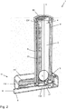
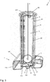
- the device 1 comprises a chamber 2 which extends along a substantially vertical.axis X.
- the chamber 2 has a lower end 3 and an upper end 4.
- the chamber 2 has rigid walls and hence maintains a constant volume during the operation of the device 1.
- the lower end 3 of the chamber 2 communicates with a first air inflow opening 31, for the inflow of exhaled air and with a second air inflow opening 32 for the inflow of inhaled air.
- the upper end 4 of the chamber 2 communicates with a first air outflow opening 41 for the outflow of exhaled air, and with a second air outflow opening 42 for the outflow of inhaled air.
- the air inhaled and exhaled by the patient during use of the device 1 always flows through the chamber 2 upwards, i.e. from the lower end 3 to the upper end 4.
- a body is provided in the chamber 2, between the lower end 3 and the upper end 4, and is vertically movable upwards when impinged upon by the inhaled or exhaled air that rises through the chamber 2, against its own weight force.
- the flow of air inhaled and exhaled by the patient directly contacts the moving body 5 which impedes the flow of air in the chamber 2 and forces the user to exercise the accessory muscles of inhalation and exhalation, namely the muscles of forced respiration.
- the position reached by the moving body 5 may be indicative of the performance of the respiratory system of the patient, e.g. of the inhalation and exhalation flow rates.
- the device 1 is equipped with a duct 6 (connected to the mouth of the patient) which is used to inhale and exhale the air that flows through the chamber 2 and impinges upon the moving body 5.
- the duct 6 is in communication with the first inflow opening 31 (for the inflow of exhaled air into the chamber 2) and with the second outflow opening 42 (to allow the outflow of inhaled air from the chamber 2).
- the inhalation and exhalation duct 6 may be connected to a flexible hose 63 which terminates with a mouthpiece, to allow inhalation and exhalation.
- the device 1 comprises an inlet hole 632, in communication with the second air inflow opening 32, for the inhaled chamber to flow into the chamber 2 from the outside.
- the device 1 comprises an outlet hole 641, in communication with the first air outflow opening 41, for the exhaled air to be exhausted to the outside after flowing out of the chamber 2.
- the first inflow opening 31 for the inflow of air into the chamber 2 is connected to the duct 6 via a first non-return valve 731 which only opens when air is exhaled.
- the first outflow opening 41 for the outflow of air from the chamber 2 is in communication with the outlet hole 641 via a second non-return valve 741 which only opens when air is exhaled.
- the second inflow opening 32 for the inflow of air into the chamber 2 is in communication with the inlet hole 632 via a third non-return valve 732 which only opens when air is inhaled.
- the second outflow opening 42 for the outflow of air from the chamber 2 is in communication with the duct 6 via a fourth non-return valve 742 which only opens when air is inhaled.
- the first non-return valve 731 and the second non-return valve 741 open and the third non-return valve 732 and the fourth non-return valve 742 close.
- the first non-return valve 731 and the second non-return valve 741 are closed and the third non-return valve 732 and the fourth non-return valve 742 are open.
- the air flow generated in the chamber 2 is directed upwards during both inhalation and exhalation.
- the chamber 2 has a frustoconical profile and the height reached by the moving body 5 in the chamber 2 is related to the flow rate of the air that flows through the chamber 2.
- the moving body 5 takes a position of equilibrium when its weight is balanced by the thrust of the air flow.
- the chamber 2 is formed inside a hollow body 23 (e.g. a body having a cylindrical outer shape) which is made of a transparent material, to show the position of the moving body 5 in the chamber 2.
- a hollow body 23 e.g. a body having a cylindrical outer shape
- the chamber 2 has an upwardly increasing tapered cross section, e.g. a frustoconical section, and the moving body 4 has a generally spherical form.
- the moving body 5 in the chamber 2 acts as a variable-area flowmeter or rotameter.
- the moving body 5 opposes resistance to the air that flows in chamber 2 and forces the user to use the muscles of inhalation and exhalation.
- the maximum height that can be reached by the moving body 5 provides an indication of the maximum lung capacity of the user in the inhalation phase and in the exhalation phase.
- the moving body 5 remains in the lifted position for a time that is proportional to the maximum capacity of the lungs of the user.
- the hollow body 23 is encircled by a second hollow body 8, also made of transparent material, thereby defining an annular chamber 81 that surrounds the chamber 2.
- the hollow body 23 and the hollow body 8 are two coaxial tubular elements closed at the top by a cap 85.
- the cap 85 may be joined to the upper end of the hollow body 8 by means of seals (not shown) to ensure air-tightness.
- the hollow body 8 is closed at its top.
- the annular chamber 81 communicates at its top with the upper end 4 of the chamber 2 via at least one opening 231 formed in the upper part of the hollow body 23.
- the chamber 81 communicates with the first air outflow opening 41 for the outflow of exhaled air, and with the second air outflow opening 42 for the outflow of inhaled air.
- the exhaled air that flows out of the first outflow opening 41 flows through the second non-return valve 741, whereas the inhaled air that flows out of the second outflow opening 42 flows through the fourth non-return valve 742.
- the device 1 may comprise a graded scale 18 to determine the vertical position of the moving body 5.
- graded scale 18 is formed on the wall of the hollow body 8.
- the pneumatic resistance between the duct 6 and the outlet opening 641 (for the exhalation phase) and the pneumatic resistance between the duct 6 and the inlet opening 632 (for the inhalation phase) may be adjusted.
- the pneumatic resistance is adjusted by adjusting the passage section between the upper end 4 of the chamber 2 and the annular chamber 81.
- the cap 85 may be designed to be rotated about the axis X and to have a closure member for varying the passage section of the opening 231 formed on the upper part of the hollow body 23.
- the lower end of the hollow body 23 and the hollow body 8 are fixed to a base 11.
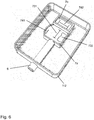
- the base 11 ha a hollow interior and comprises an upper half-shell 111 and a lower half-shell 112 which are joined, for example, by means of quick snap connectors.
- the two half shells 111, 112 are formed with a substantially and/or generally rigid material, for example a thermoplastic material.
- the upper half shell 111 of the base 11 has a seat 12 for receiving of the lower ends of the hollow body 23 and the hollow body 8.
- the duct 6 is rigidly joined to the lower half-shell 112.
- the seat 12 is specially shaped to ensure form-fit with the lower ends of the hollow body 23 and the hollow body 8.
- the seat 12 has the first inflow opening 31 for the inflow of exhaled air into the chamber 2, and the second inflow opening 32 for the inflow in inhaled air into the chamber 2 formed therein.
- the seat 12 also has the first outflow opening 41 for the outflow of exhaled air and the second outflow opening 42 for the outflow of inhaled air formed therein
- the inflow openings 31, 32 are situated within the section of the chamber 2, whereas the outflow openings 41, 42 are situated within the section of the annular chamber 81.
- the inlet hole 632 for the air inhaled from the outside into the chamber 2 to flow into the chamber, and the outlet hole 641, for the exhaled air to be exhausted to the outside after flowing out of the chamber 2, are formed in the wall of the lower half-shell 112.
- the non-return valves 731, 732, 741, 742 are valves that allow air to flow in one direction only.
- non-return valves 731, 732, 741, 742 are all located inside the base 11.
- the non-return valves 731, 732, 741, 742 may be formed with flexible diaphragms having cuts formed throughout their thickness.
- the full-thickness cuts defines edges that are normally closed and tend to move apart from each other and create a passage lumen, when a pressure difference is generated between the two opposite faces of the membrane.
- a perforated or grated support surface is created on one side of the diaphragm, to prevent the edges of the cut to be lifted in one direction.
- the lumen only opens if the side of the diaphragm that faces the perforated or grated surface is at a pressure above the pressure on the opposite side of the diaphragm.
- first, second and third non-return valves 731, 732, 741 are formed with a first diaphragm 7a having three distinct full-thickness cuts.
- the fourth non-return valve 742 is formed with a second diaphragm7b with a full-thickness cut.
- the first diaphragm 7a is placed in a first seat 1121, formed in the lower half-shell 112, which is in communication with the duct 6 (via an opening 61), with the outlet opening 641 and with the inlet opening 632.
- a frame 91 projects out of the first or upper half-shell 111 toward the first seat 1121, to thereby the outer edges of the first diaphragm 7a and ensure air-tightness.
- the first seat 1121 has a perforated portion therein, to prevent the second non-return valve 641 from opening when the user is in the inhalation phase.
- the frame 91 has therein a first grated portion to prevent the first non-return valve 731 from opening during the inhalation phase, and a second grated portion to prevent the third non-return valve 732 from opening during the inhalation phase.
- the second diaphragm 7b is placed in a second seat 1122 formed in the lower half-shell 112, which is in communication with the duct 6 (via an opening 62).
- the edges of the second diaphragm7b are compressed by a frame 92 that projects out of the first half-shell 111 and faces the second seat 7b.
- the frame 92 has a perforated surface therein, which prevents the fourth non-return valve 742 from opening during the exhalation phase.
- the diaphragms 7a, 7b can be made, for example, of medical grade silicone or medical grade silicone-based materials, polyurethane or other flexible polymeric materials and may have an average thickness ranging, for example, from 0.5 mm to 4 mm.
- the four non-return valves 731, 732, 741, 742 are all formed with a single diaphragm made of a flexible material.
- the half shells 111, 112 of the base 11 are made of a transparent material and the diaphragms 7a, 7b of the non-return valves 731, 732, 741, 742 are made of a colored material.
Landscapes
- Health & Medical Sciences (AREA)
- General Health & Medical Sciences (AREA)
- Physical Education & Sports Medicine (AREA)
- Life Sciences & Earth Sciences (AREA)
- Biophysics (AREA)
- Orthopedic Medicine & Surgery (AREA)
- Pulmonology (AREA)
- Respiratory Apparatuses And Protective Means (AREA)
- Measurement Of The Respiration, Hearing Ability, Form, And Blood Characteristics Of Living Organisms (AREA)
- Pharmaceuticals Containing Other Organic And Inorganic Compounds (AREA)
Applications Claiming Priority (1)
| Application Number | Priority Date | Filing Date | Title |
|---|---|---|---|
| IT102018000010124A IT201800010124A1 (it) | 2018-11-07 | 2018-11-07 | Dispositivo di fisioterapia respiratoria |
Publications (3)
| Publication Number | Publication Date |
|---|---|
| EP3650084A1 true EP3650084A1 (de) | 2020-05-13 |
| EP3650084B1 EP3650084B1 (de) | 2025-07-23 |
| EP3650084C0 EP3650084C0 (de) | 2025-07-23 |
Family
ID=65409323
Family Applications (1)
| Application Number | Title | Priority Date | Filing Date |
|---|---|---|---|
| EP19206614.0A Active EP3650084B1 (de) | 2018-11-07 | 2019-10-31 | Atemtherapiegerät |
Country Status (2)
| Country | Link |
|---|---|
| EP (1) | EP3650084B1 (de) |
| IT (1) | IT201800010124A1 (de) |
Citations (9)
| Publication number | Priority date | Publication date | Assignee | Title |
|---|---|---|---|---|
| US3695608A (en) | 1970-08-17 | 1972-10-03 | Lourie Visual Etudes Inc | Device for practicing breath control |
| US3898987A (en) | 1973-10-09 | 1975-08-12 | James O Elam | Breathing responsive device and method |
| US4025070A (en) | 1976-04-19 | 1977-05-24 | Cutter Laboratories, Inc. | Respiratory exerciser |
| US4114607A (en) | 1976-02-11 | 1978-09-19 | Chesebrough-Pond's Inc. | Inhalation device |
| US4138105A (en) | 1977-02-28 | 1979-02-06 | Cutter Laboratories, Inc. | Respiratory exerciser |
| US4171804A (en) | 1977-09-02 | 1979-10-23 | Thead William H Jr | Respiratory exerciser and the like |
| US4183361A (en) | 1978-02-27 | 1980-01-15 | Russo Ronald D | Respiratory exercising device |
| US20140150801A1 (en) | 2011-04-28 | 2014-06-05 | MichaelJ. Rusher | Airway pressure control devices with flutter valve |
| US9561399B2 (en) | 2015-04-28 | 2017-02-07 | Lung Trainers, LLC | Lung instrument training device and method |
-
2018
- 2018-11-07 IT IT102018000010124A patent/IT201800010124A1/it unknown
-
2019
- 2019-10-31 EP EP19206614.0A patent/EP3650084B1/de active Active
Patent Citations (9)
| Publication number | Priority date | Publication date | Assignee | Title |
|---|---|---|---|---|
| US3695608A (en) | 1970-08-17 | 1972-10-03 | Lourie Visual Etudes Inc | Device for practicing breath control |
| US3898987A (en) | 1973-10-09 | 1975-08-12 | James O Elam | Breathing responsive device and method |
| US4114607A (en) | 1976-02-11 | 1978-09-19 | Chesebrough-Pond's Inc. | Inhalation device |
| US4025070A (en) | 1976-04-19 | 1977-05-24 | Cutter Laboratories, Inc. | Respiratory exerciser |
| US4138105A (en) | 1977-02-28 | 1979-02-06 | Cutter Laboratories, Inc. | Respiratory exerciser |
| US4171804A (en) | 1977-09-02 | 1979-10-23 | Thead William H Jr | Respiratory exerciser and the like |
| US4183361A (en) | 1978-02-27 | 1980-01-15 | Russo Ronald D | Respiratory exercising device |
| US20140150801A1 (en) | 2011-04-28 | 2014-06-05 | MichaelJ. Rusher | Airway pressure control devices with flutter valve |
| US9561399B2 (en) | 2015-04-28 | 2017-02-07 | Lung Trainers, LLC | Lung instrument training device and method |
Also Published As
| Publication number | Publication date |
|---|---|
| EP3650084B1 (de) | 2025-07-23 |
| IT201800010124A1 (it) | 2020-05-07 |
| EP3650084C0 (de) | 2025-07-23 |
Similar Documents
| Publication | Publication Date | Title |
|---|---|---|
| US8118713B2 (en) | Respiratory muscle endurance training device and method for the use thereof | |
| EP0678306B1 (de) | Vorrichtung zum Aufrechterhalten eines positiven Ausatemdruckes | |
| JP5307715B2 (ja) | 呼吸筋耐久力訓練器具 | |
| US4210155A (en) | Inspirational inhalation spirometer apparatus | |
| US20040146842A1 (en) | Training device for the respiratory system | |
| CA2826724C (en) | Aerosol delivery apparatus with positive expiratory pressure capacity | |
| US4298023A (en) | Spring loaded exhalation valve | |
| USRE46210E1 (en) | Patient interface member for use in an aerosol inhalation system | |
| US7841341B2 (en) | Interface accessory for use with an aerosol inhalation system | |
| US20120094806A1 (en) | Adjustable Inhalation Resistence Exercise Device | |
| JPH06205832A (ja) | 弁機構およびそれを備えたエアゾール吸入装置 | |
| WO2004110857A2 (en) | Underwater breathing devices and methods | |
| EP2777734B1 (de) | Einwegbare Auslaufeinheit für eine Medizinische Atmungsvorrichtung | |
| KR20220043269A (ko) | 산소공급수단을 구비한 투명마스크 | |
| EP3650084B1 (de) | Atemtherapiegerät | |
| EP3202449A1 (de) | Winkelverbinder mit anti-asphyxie-ventilanordnung für atemmaske | |
| CN114797027A (zh) | 一种医院呼吸科用呼吸训练装置 | |
| KR20230016165A (ko) | 호기 포트가 있는 흡기 저항 밸브 시스템 | |
| JP4781748B2 (ja) | 声門下狭窄患者用会話可能な気管切開チューブ | |
| ES1306247U (es) | Dispositivo de fijación bucal para entrenamiento físico. | |
| PL249340B1 (pl) | Urządzenie do terapii oddechowej |
Legal Events
| Date | Code | Title | Description |
|---|---|---|---|
| PUAI | Public reference made under article 153(3) epc to a published international application that has entered the european phase |
Free format text: ORIGINAL CODE: 0009012 |
|
| STAA | Information on the status of an ep patent application or granted ep patent |
Free format text: STATUS: THE APPLICATION HAS BEEN PUBLISHED |
|
| AK | Designated contracting states |
Kind code of ref document: A1 Designated state(s): AL AT BE BG CH CY CZ DE DK EE ES FI FR GB GR HR HU IE IS IT LI LT LU LV MC MK MT NL NO PL PT RO RS SE SI SK SM TR |
|
| AX | Request for extension of the european patent |
Extension state: BA ME |
|
| STAA | Information on the status of an ep patent application or granted ep patent |
Free format text: STATUS: REQUEST FOR EXAMINATION WAS MADE |
|
| 17P | Request for examination filed |
Effective date: 20201102 |
|
| RBV | Designated contracting states (corrected) |
Designated state(s): AL AT BE BG CH CY CZ DE DK EE ES FI FR GB GR HR HU IE IS IT LI LT LU LV MC MK MT NL NO PL PT RO RS SE SI SK SM TR |
|
| STAA | Information on the status of an ep patent application or granted ep patent |
Free format text: STATUS: EXAMINATION IS IN PROGRESS |
|
| 17Q | First examination report despatched |
Effective date: 20230209 |
|
| GRAP | Despatch of communication of intention to grant a patent |
Free format text: ORIGINAL CODE: EPIDOSNIGR1 |
|
| STAA | Information on the status of an ep patent application or granted ep patent |
Free format text: STATUS: GRANT OF PATENT IS INTENDED |
|
| INTG | Intention to grant announced |
Effective date: 20250204 |
|
| RIN1 | Information on inventor provided before grant (corrected) |
Inventor name: BERNUCCI, STEFANO Inventor name: APOLET, JOSEK BEREK |
|
| GRAJ | Information related to disapproval of communication of intention to grant by the applicant or resumption of examination proceedings by the epo deleted |
Free format text: ORIGINAL CODE: EPIDOSDIGR1 |
|
| STAA | Information on the status of an ep patent application or granted ep patent |
Free format text: STATUS: EXAMINATION IS IN PROGRESS |
|
| INTC | Intention to grant announced (deleted) | ||
| GRAP | Despatch of communication of intention to grant a patent |
Free format text: ORIGINAL CODE: EPIDOSNIGR1 |
|
| STAA | Information on the status of an ep patent application or granted ep patent |
Free format text: STATUS: GRANT OF PATENT IS INTENDED |
|
| GRAS | Grant fee paid |
Free format text: ORIGINAL CODE: EPIDOSNIGR3 |
|
| GRAA | (expected) grant |
Free format text: ORIGINAL CODE: 0009210 |
|
| STAA | Information on the status of an ep patent application or granted ep patent |
Free format text: STATUS: THE PATENT HAS BEEN GRANTED |
|
| INTG | Intention to grant announced |
Effective date: 20250527 |
|
| REG | Reference to a national code |
Ref country code: DE Ref legal event code: R081 Ref document number: 602019072834 Country of ref document: DE Owner name: MEDINET S.R.L., IT Free format text: FORMER OWNER: MEDINET S.R.L., MAILAND/MILAN, IT |
|
| AK | Designated contracting states |
Kind code of ref document: B1 Designated state(s): AL AT BE BG CH CY CZ DE DK EE ES FI FR GB GR HR HU IE IS IT LI LT LU LV MC MK MT NL NO PL PT RO RS SE SI SK SM TR |
|
| REG | Reference to a national code |
Ref country code: GB Ref legal event code: FG4D |
|
| REG | Reference to a national code |
Ref country code: CH Ref legal event code: EP |
|
| REG | Reference to a national code |
Ref country code: IE Ref legal event code: FG4D |
|
| REG | Reference to a national code |
Ref country code: DE Ref legal event code: R096 Ref document number: 602019072834 Country of ref document: DE |
|
| U01 | Request for unitary effect filed |
Effective date: 20250728 |
|
| U07 | Unitary effect registered |
Designated state(s): AT BE BG DE DK EE FI FR IT LT LU LV MT NL PT RO SE SI Effective date: 20250807 |
|
| U20 | Renewal fee for the european patent with unitary effect paid |
Year of fee payment: 7 Effective date: 20251022 |
|
| PG25 | Lapsed in a contracting state [announced via postgrant information from national office to epo] |
Ref country code: IS Free format text: LAPSE BECAUSE OF FAILURE TO SUBMIT A TRANSLATION OF THE DESCRIPTION OR TO PAY THE FEE WITHIN THE PRESCRIBED TIME-LIMIT Effective date: 20251123 |
|
| PG25 | Lapsed in a contracting state [announced via postgrant information from national office to epo] |
Ref country code: NO Free format text: LAPSE BECAUSE OF FAILURE TO SUBMIT A TRANSLATION OF THE DESCRIPTION OR TO PAY THE FEE WITHIN THE PRESCRIBED TIME-LIMIT Effective date: 20251023 |
|
| PG25 | Lapsed in a contracting state [announced via postgrant information from national office to epo] |
Ref country code: HR Free format text: LAPSE BECAUSE OF FAILURE TO SUBMIT A TRANSLATION OF THE DESCRIPTION OR TO PAY THE FEE WITHIN THE PRESCRIBED TIME-LIMIT Effective date: 20250723 |
|
| PG25 | Lapsed in a contracting state [announced via postgrant information from national office to epo] |
Ref country code: GR Free format text: LAPSE BECAUSE OF FAILURE TO SUBMIT A TRANSLATION OF THE DESCRIPTION OR TO PAY THE FEE WITHIN THE PRESCRIBED TIME-LIMIT Effective date: 20251024 |
|
| PG25 | Lapsed in a contracting state [announced via postgrant information from national office to epo] |
Ref country code: PL Free format text: LAPSE BECAUSE OF FAILURE TO SUBMIT A TRANSLATION OF THE DESCRIPTION OR TO PAY THE FEE WITHIN THE PRESCRIBED TIME-LIMIT Effective date: 20250723 |
|
| PG25 | Lapsed in a contracting state [announced via postgrant information from national office to epo] |
Ref country code: RS Free format text: LAPSE BECAUSE OF FAILURE TO SUBMIT A TRANSLATION OF THE DESCRIPTION OR TO PAY THE FEE WITHIN THE PRESCRIBED TIME-LIMIT Effective date: 20251023 |
|
| PG25 | Lapsed in a contracting state [announced via postgrant information from national office to epo] |
Ref country code: ES Free format text: LAPSE BECAUSE OF FAILURE TO SUBMIT A TRANSLATION OF THE DESCRIPTION OR TO PAY THE FEE WITHIN THE PRESCRIBED TIME-LIMIT Effective date: 20250723 |
|
| PG25 | Lapsed in a contracting state [announced via postgrant information from national office to epo] |
Ref country code: SM Free format text: LAPSE BECAUSE OF FAILURE TO SUBMIT A TRANSLATION OF THE DESCRIPTION OR TO PAY THE FEE WITHIN THE PRESCRIBED TIME-LIMIT Effective date: 20250723 |
|
| PG25 | Lapsed in a contracting state [announced via postgrant information from national office to epo] |
Ref country code: CZ Free format text: LAPSE BECAUSE OF FAILURE TO SUBMIT A TRANSLATION OF THE DESCRIPTION OR TO PAY THE FEE WITHIN THE PRESCRIBED TIME-LIMIT Effective date: 20250723 |
|
| PG25 | Lapsed in a contracting state [announced via postgrant information from national office to epo] |
Ref country code: SK Free format text: LAPSE BECAUSE OF FAILURE TO SUBMIT A TRANSLATION OF THE DESCRIPTION OR TO PAY THE FEE WITHIN THE PRESCRIBED TIME-LIMIT Effective date: 20250723 |