EP3649879A1 - Dispositif de protection individuelle et vêtement comprenant ce dispositif de protection - Google Patents
Dispositif de protection individuelle et vêtement comprenant ce dispositif de protection Download PDFInfo
- Publication number
- EP3649879A1 EP3649879A1 EP19208045.5A EP19208045A EP3649879A1 EP 3649879 A1 EP3649879 A1 EP 3649879A1 EP 19208045 A EP19208045 A EP 19208045A EP 3649879 A1 EP3649879 A1 EP 3649879A1
- Authority
- EP
- European Patent Office
- Prior art keywords
- inflatable member
- protective device
- user
- garment
- zone
- Prior art date
- Legal status (The legal status is an assumption and is not a legal conclusion. Google has not performed a legal analysis and makes no representation as to the accuracy of the status listed.)
- Granted
Links
Images

Classifications
-
- A—HUMAN NECESSITIES
- A41—WEARING APPAREL
- A41D—OUTERWEAR; PROTECTIVE GARMENTS; ACCESSORIES
- A41D13/00—Professional, industrial or sporting protective garments, e.g. surgeons' gowns or garments protecting against blows or punches
- A41D13/015—Professional, industrial or sporting protective garments, e.g. surgeons' gowns or garments protecting against blows or punches with shock-absorbing means
- A41D13/018—Professional, industrial or sporting protective garments, e.g. surgeons' gowns or garments protecting against blows or punches with shock-absorbing means inflatable automatically
-
- A—HUMAN NECESSITIES
- A41—WEARING APPAREL
- A41D—OUTERWEAR; PROTECTIVE GARMENTS; ACCESSORIES
- A41D2300/00—Details of garments
- A41D2300/30—Closures
- A41D2300/322—Closures using slide fasteners
Definitions
- the present disclosure relates to a protective device for personal protection, preferably of the type which can be worn and including an inflatable member designed to protect from impacts and/or falls a user, for example a passenger or a rider of motorcycle or a horse rider during a horse race, or a similar user, during a sporting and/or working activity.
- the inflatable member creates, around the part of the user's body, an air cushion which allows the user's body to be protected against impacts.
- the inflatable member normally has a shape or form which is similar to that of a vest or waistcoat so that it may be easily worn by a user or so that it may be associated with a garment.
- the inflatable member may be curved so as to favour adaptation to a user's body. Consequently, the inflatable member has, like a normal jacket or article which can be worn, folded or curved zones so as to adapt to the anatomy of the human body.
- the inflatable member has, like a normal jacket, superficial discontinuities or interruptions, for example in a central zone of the chest.
- the inflatable member may be closed by means of a zip associated directly with the inflatable member, or may be kept closed by the zip, or other closing device, of the jacket.
- Other zones where there are surfaces discontinuities or interruptions are, for example, those situated underneath the armpits along the sides.
- the similarity in terms of form and shape of the inflatable member with a vest or waistcoat, or in any case the curved shape if on the one hand it makes the inflatable member easier to wear, on the other hand it may negatively affect the protective capacity of the inflatable member, in particular in the region of superficial interruptions or discontinuities.
- the inventor of the present disclosure has recognized that, in some bags, in order to prevent superficial interruptions on the chest a personal protective device has been developed where the inflatable member includes at least two portions of the inflatable member which are superimposed so as to define a corresponding overmounting or overlapping zone and where a zip is associated with the two inflatable member portions in the overlapping zone. In this way, when the inflatable member is inflated, the two portions of the inflatable member may be superimposed or at least arranged side-by-side.
- WO2014199308A1 in the name of the Applicant.
- a technical problem encountered by the inventor of the present disclosure lies in the fact that the solution proposed in WO2014199308A1 , although advantageous from many points of view, is not entirely satisfactory for cases where the inflatable member has particular forms or forms which are adapted to the anatomy of the human body.
- the zip does not match the curvature of the human body.
- the inflatable member has a curvature in the zone of the zip, when inflation is performed, the zip is subject to excessive tension or must be designed with dimensions such as to withstand a significant movement away from each other of the inflatable member portions owing to the curvature of the two inflatable member portions.
- a protective device according to the independent claim 1 is provided. Further aspects of the present disclosure are defined in the dependent claims and by a garment as defined in the respective claims.
- the protective device includes an inflatable member intended to protect at least partially a zone of a user's body, the inflatable member comprising at least two inflatable member portions.
- the personal protective device includes at least one connecting device or structure associated with the first portion of the inflatable member and the second portion of the inflatable member and arranged on an inner side of the inflatable member, or side directed towards the user, of the first portion of the inflatable member and the second portion of the inflatable member, namely user side.
- the inflatable member has a curved shape or curved profile at least in an inflated condition
- the connecting device or structure is arranged on an inner side or concave side of said curved shape or curved profile.
- the device when the device is a wearable device and the inflatable member has preferably the form of a waistcoat, or life jacket, or similar form, it defines a housing zone or an internal zone intended to house the body of a user.
- the connecting structure such as a zip, Velcro fastener, or similar connecting structure, is arranged on a side of the inflatable member directed towards said housing zone, i.e. a zone which, when the device is worn, is directed towards the user.
- the inflatable member portions may be portions of a single inflatable member or portions of two different inflatable members. These inflatable member portions may be terminal or end portions facing each other, or are adjacent, when the inflatable member is worn.
- the connecting structure is arranged on the side of the inflatable member directed towards the internal zone or towards said zone for housing a user's body.
- the connecting structure is fixed onto an inner side of the inflatable member and is hidden from view.
- the inflatable member has preferably, when worn, a side hidden from view on the outside and the connecting structure is arranged on this side which is hidden from view.
- the inflatable member portions in fact cover the connecting structure.
- the connecting structure is accessible from an outer side of the protective device.
- the connecting structure is accessible by displacing from the outside the two inflatable member portions which face each other.
- each inflatable member portion is associated with the connecting and closing structure on the inner side towards the user's body, so as to ensure stable closing of the two terminal or end portions of the inflatable member and without any tension or minimal tension of the connecting structure.
- the two portions of a same inflatable member or of two inflatable members are also superimposed. Therefore, a first portion of the inflatable member and a second portion of the inflatable member are superimposed in a corresponding overmounting or overlapping area and the connecting structure connects on the inner side the two portions in the overmounting area.
- the connecting structure is therefore accessible by displacing the two areas of the inflatable member portions relative to each other in an overmounting condition.
- one or both the inflatable member portions are structured or configured so as to have a different expansion between an inner side directed towards the user and an outer side opposite to the inner side.
- each inflatable member portion may be made using the technology described in the international patent application WO2017163196A1 in the name of the Applicant. Consequently, in the inflated condition one or both of the two inflatable member portions may have an inner side which is more rigid or less stretched (i.e. a side which yields less to inflation) and an outer side which is more inflated and therefore more stretched (i.e. a side which yields more to inflation).
- the connecting structure is fixed on the inner side, namely where the two inflatable member portions are more rigid and therefore flat and may be connected more easily.
- the connecting structure may be arranged centred with respect to the zone to be protected, for example on the chest, in the centre of the chest so as to allow easy central opening/closing of the protective device.
- the two inflatable member portions may be superimposed, for example, also on the sides of a user, or in another part of the body.
- the connecting and closing structure comprises two panels, preferably made of soft material, such as fabric.
- Each of the two panels is fixed, for example sewn or glued, on one side to one of the two inflatable member portions, even more preferably, if overmounting is present, in a zone adjacent to the overlapping or overmounting area.
- the other side of the panel is free or movable, is directed towards the overmounting area and is provided with one of the two components of the zip or any other connecting structure.
- the two inflatable member portions superimposed the two panels are situated close together and may be connected, for example by means of a zip.
- Each of the two panels may be fixed in an intermediate zone between the overmounting area and a non-overmounting area of the inflatable member.
- the two panels may be pieces or panels of cloth or fabric which extend along the inflatable member portions. These panels may be provided with a zip portion or other connecting device of the type able to be opened or reversed.
- a zip portion associated with a panel is connected in a reversible or temporary manner to a complementary zip portion associated with the other panel.
- a Velcro portion associated with a panel and a complementary portion of Velcro associated with the other panel may be connected together.
- the two superimposed portions of the inflatable member move away momentarily from each other with a reduction or elimination of an mutual overmounting area.
- the connecting structure is located on the inner side, and preferably the side which is flatter and yields less to expansion or inflation, the connecting structure is tensioned to a small degree or minimally.
- the inflatable member described above may be easily incorporated inside a garment, for example inside respective pockets of a garment.
- the garment may be structured so as to have pockets, or a single pocket, designed to receive the inflatable member.
- the connecting structure may be fixed not directly to the inflatable member, but on an inner side of the garment or on a lining, or for example be fixed directly or indirectly to the respective pocket or pocket portion which houses each inflatable member portion.
- the connecting structure described above may be fixed to the garment so as to be indirectly connected to the inflatable member of the personal protection device, on the inner side, for example the inner lining of the garment.
- the inflatable member may be fitted externally, or lined, with a fabric suitable for clothing, and assume the appearance of a garment which may be worn on its own.
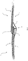
- the reference number 10 indicates a personal protective device according to the present disclosure in accordance with an embodiment of the present disclosure.
- the personal protection device 10 comprises an inflatable member 12 which is designed to assume substantially a first rest condition or deflated condition and a second active condition or inflated condition.
- the modes of inflating the inflatable member 12 will be described in the description below.
- the active inflated condition may be assumed in the event of an impact, or a general danger, or may be assumed permanently so as to provide continuous protection.
- the inflatable member 12 is formed as a vest and is designed to surround an upper zone or the bust of a user's body.
- the inflatable element 12 which may be made using the technology described in the patent application PCT/IB2009/055512 and in the patent application PCT/IT2009/000547 , which are cited herein as a reference source in their entirety in the present disclosure, or may be made more preferably using the technology described in the patent application WO2016178143A1 , or even more preferably in the patent application WO2017163196A1 PCT .
- it consists preferably of an inflatable member with threads, formed by meshes and walls as described in these patent applications, and even more preferably with a curved configuration due to a varied expansion capacity between an inner side directed towards the user I and an outer side E.
- the inflatable member 12 includes a first inflatable member portion 20 and a second inflatable member portion 21.
- This first inflatable member portion 20 and second inflatable member portion 21 are terminal or end portions of the inflatable member 12 and are preferably partially superimposed.
- the first inflatable member portion 20 and second inflatable member portion 21 are portions arranged at the free ends of the inflatable member 12.
- An overlapping area A corresponds to a central zone of the chest.
- the first portion 20 and the second portion 21 of the inflatable member 12 are end portions situated in the chest region of a user. It should also be pointed out that, taking into account the overmounting or overlapping area A, the first portion 20 and the second portion 21 have in fact free ends in the overmounting area and may be easily displaced.
- the personal protective device 10 includes one or more connecting and closing devices or structures 50 associated with the first portion 20 of the inflatable member and second portion 21 of the inflatable member on an inner side I directed towards the user, preferably in the overlapping area A.
- the connecting device or structure 50 is a zip-type structure, for example in the overlapping area A.
- first portion 20 of the inflatable member and second portion 21 of the inflatable member are each associated with a part of the connecting structure 50 which is connected to the complementary part of the connecting structure 50 so as to ensure stable closing of the first portion 20, inflatable member and second portion 21 of the inflatable member, on an inner side I directed towards the user.
- the inner side directed towards the user although it is more awkward to reach for the user, is however that side where the inflatable member extends has a smaller radius of curvature so as to surround the body of the user.
- the connecting structure 50 is configured so as to be accessible from the outer side E, preferably by displacing the two superimposed ends of the respective portions 20, 21 of the inflatable member 12.
- the connecting structure 50 such as that which is situated on the user's chest, comprises two flaps or panels made of soft material 51, 52 such as fabric.
- Each of the two flaps 51, 52 is fixed, for example stitched or glued to one of the two portions 20, 21 of the inflatable member 12 in a zone adjacent to the overlapping or overmounting area A.
- These panels may also extend over the whole of the inflatable member 12, lining it on the inner side I.
- the two panels 51, 52 are situated close and may be connected together.
- the two panels 51, 52 may be pieces or panels of fabric or cloth which extend over an entire length of the portions 20, 21 of the inflatable member 12, such as to allow a continuous connection between the two portions 20, 21.
- These panels 51, 52 may be provided at respective ends with a zip portion 53, 54 or other connecting device of the type which can be opened or reversed.
- a zip portion associated with a panel 51 is connected in a reversible or temporary manner to a complementary zip portion associated with the other panel 52 so as to form the connecting structure 50.
- the assembly consisting of the connecting structure 50 and the panels 50, 52 may be understood as being a single zip structure.
- the two inflatable member portions 20, 21 may be superimposed, for example, on the chest of a user, on the inner side I of the inflatable member, and the connecting structure 50 may be arranged in the centre of the chest on the user side so as to allow central opening/closing of the protective device 10.
- the inflatable member 12 described above may be easily incorporated inside a garment, such as a jacket 100 ( Figure 2 and Figure 5 ), for example inside respective pockets 80, 81 of a garment, wherein each pocket is intended to receive a respective inflatable member portion 20, 21.
- the pockets 80, 81 may also be understood as being portions of a single pocket which is present on the inner side, or user side, of the garment.
- the pockets may also be understood as being a lining which lines only internally the inflatable member.
- the garment 100 may be designed with a structure having pockets 80, 81 which each contain a respective portion 20, 21 of the inflatable member 12 and are superimposed in the same way as the inflatable member. More particularly, each pocket 80, 81 has an inner wall which acts as an inner lining and an outer wall which acts as a visible surface of the garment.
- the connecting structure 50 is connected to the pockets 80, 81 as in the preceding embodiment, by means of fabric panels or similar connecting means 51, 52.
- the connecting structure 50 is therefore connected to the internal lining of the respective pocket which houses the inflatable member.
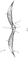
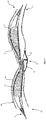
- the inflatable member is made using the technology described in the aforementioned patent application WO2017163196A1 . Consequently, one or each of the two portions 20, 21 of the inflatable member has in the inflated condition one side which is more inflated, expanded and/or curved, directed towards the outside E, and a more rigid, flat or less inflated side on the inner side I.
- the connecting structure 50 is arranged on the inner side I directed towards the user, the two portions which form the connecting structure 50, for example the two zip portions, may be connected to the flatter sides of the two portions 20, 21.
- the connecting structure 50 may therefore be subject to less tensioning during inflation.
- the inflatable element in the inflated condition has, on the outer side E, two humps or two curved profiles arranged side-by-side or slightly superimposed and, on the inner side, two substantially flat profiles arranged side-by-side or slightly superimposed and connected together. Consequently, when the inflatable element 12 is inflated, the two portions 20, 21 move away from each other with a greater degree of expansion on the outer side E. In fact, the overall extension of the protective device increases on the outer side E more than on the inner side I and, owing to the special feature of the present invention, with a minimum effect in terms of tension on the connecting structure 50.
- the protective device 10 is designed to cooperate with special activation means (not shown) which are operationally connected to the cylinder (not shown) containing compressed cold gas, such as helium.
- the cylinder may be provided with a respective shut-off valve (not shown).
- the inflation fluid source may comprise gas generators preferably of the pyrotechnical or other hybrid type or other types known according to the state of the art.
- Opening of the shut-off valve of each inflation cylinder is preferably controlled by a control unit depending on detection of the state of the vehicle/rider system; for example said control unit may implement a system for predicting the fall which allows early identification of the fall event and a reliable prediction of this by means of accelerometer sensors fixed to the vehicle (or rider) and a unit for processing the signals produced by said sensors.
- the device according to the present disclosure may also be applied using an activation cable connected to a vehicle ridden by a user, which cable activates inflation of the inflatable member following the movement of the user away from the vehicle, following a fall or a sudden impact.
- an activation cable connected to a vehicle ridden by a user, which cable activates inflation of the inflatable member following the movement of the user away from the vehicle, following a fall or a sudden impact.
- Use of a cable is employed in particular in the horse-riding sector.
- activation and inflation means may be integrated in the protection device according to the present invention or located on the outside thereof.
Landscapes
- Health & Medical Sciences (AREA)
- General Health & Medical Sciences (AREA)
- Physical Education & Sports Medicine (AREA)
- Engineering & Computer Science (AREA)
- Textile Engineering (AREA)
- Professional, Industrial, Or Sporting Protective Garments (AREA)
Applications Claiming Priority (1)
| Application Number | Priority Date | Filing Date | Title |
|---|---|---|---|
| IT102018000010217A IT201800010217A1 (it) | 2018-11-09 | 2018-11-09 | Dispositivo di protezione personale e indumento includente detto dispositivo di protezione |
Publications (2)
| Publication Number | Publication Date |
|---|---|
| EP3649879A1 true EP3649879A1 (fr) | 2020-05-13 |
| EP3649879B1 EP3649879B1 (fr) | 2022-09-07 |
Family
ID=65409363
Family Applications (1)
| Application Number | Title | Priority Date | Filing Date |
|---|---|---|---|
| EP19208045.5A Active EP3649879B1 (fr) | 2018-11-09 | 2019-11-08 | Dispositif de protection individuelle et vêtement comprenant ce dispositif de protection |
Country Status (2)
| Country | Link |
|---|---|
| EP (1) | EP3649879B1 (fr) |
| IT (1) | IT201800010217A1 (fr) |
Citations (8)
| Publication number | Priority date | Publication date | Assignee | Title |
|---|---|---|---|---|
| WO2009047733A2 (fr) * | 2007-10-10 | 2009-04-16 | Dainese S.P.A. | Dispositif de protection personnel avec sac gonflable et vêtement comprenant un tel dispositif |
| WO2009055512A2 (fr) | 2007-10-22 | 2009-04-30 | The Scripps Research Institute | Procédés et compositions pour obtenir des cristaux haute résolution de protéines membranaires |
| JP2010125992A (ja) * | 2008-11-27 | 2010-06-10 | Honda Motor Co Ltd | エアバッグ付きジャケット |
| WO2011148353A1 (fr) * | 2010-05-28 | 2011-12-01 | Freni Brembo S.P.A. | Vêtement de protection équipé d'un airbag |
| WO2014199308A1 (fr) | 2013-06-12 | 2014-12-18 | Dainese S.P.A. | Dispositif de protection personnelle |
| EP2956026A2 (fr) * | 2013-02-15 | 2015-12-23 | Helite | Équipement de protection individuelle destiné à protéger un utilisateur |
| WO2016178143A1 (fr) | 2015-05-06 | 2016-11-10 | Dainese S.P.A. | Dispositif de protection et procédé de fabrication d'un tel dispositif de protection |
| WO2017163196A1 (fr) | 2016-03-24 | 2017-09-28 | Dainese S.P.A. | Dispositif de protection |
-
2018
- 2018-11-09 IT IT102018000010217A patent/IT201800010217A1/it unknown
-
2019
- 2019-11-08 EP EP19208045.5A patent/EP3649879B1/fr active Active
Patent Citations (8)
| Publication number | Priority date | Publication date | Assignee | Title |
|---|---|---|---|---|
| WO2009047733A2 (fr) * | 2007-10-10 | 2009-04-16 | Dainese S.P.A. | Dispositif de protection personnel avec sac gonflable et vêtement comprenant un tel dispositif |
| WO2009055512A2 (fr) | 2007-10-22 | 2009-04-30 | The Scripps Research Institute | Procédés et compositions pour obtenir des cristaux haute résolution de protéines membranaires |
| JP2010125992A (ja) * | 2008-11-27 | 2010-06-10 | Honda Motor Co Ltd | エアバッグ付きジャケット |
| WO2011148353A1 (fr) * | 2010-05-28 | 2011-12-01 | Freni Brembo S.P.A. | Vêtement de protection équipé d'un airbag |
| EP2956026A2 (fr) * | 2013-02-15 | 2015-12-23 | Helite | Équipement de protection individuelle destiné à protéger un utilisateur |
| WO2014199308A1 (fr) | 2013-06-12 | 2014-12-18 | Dainese S.P.A. | Dispositif de protection personnelle |
| WO2016178143A1 (fr) | 2015-05-06 | 2016-11-10 | Dainese S.P.A. | Dispositif de protection et procédé de fabrication d'un tel dispositif de protection |
| WO2017163196A1 (fr) | 2016-03-24 | 2017-09-28 | Dainese S.P.A. | Dispositif de protection |
Also Published As
| Publication number | Publication date |
|---|---|
| IT201800010217A1 (it) | 2020-05-09 |
| EP3649879B1 (fr) | 2022-09-07 |
Similar Documents
| Publication | Publication Date | Title |
|---|---|---|
| US12121083B2 (en) | Standalone wearable protector and protective clothing assembly | |
| EP3007573B1 (fr) | Dispositif de protection personnelle | |
| EP3498117B1 (fr) | Vêtement de protection d'un utilisateur comprenant un élément gonflable | |
| CN113271800B (zh) | 包括可充气保护装置的服装 | |
| EP2994002B1 (fr) | Dispositif de protection individuelle | |
| WO2000051454A8 (fr) | Vetement de protection | |
| EP3007572B1 (fr) | Dispositif de protection personnelle | |
| EP3649879B1 (fr) | Dispositif de protection individuelle et vêtement comprenant ce dispositif de protection | |
| EP4483734A1 (fr) | Vêtement de protection | |
| KR102790182B1 (ko) | 인체보호장치 | |
| EP2740376B1 (fr) | Vêtement adapté pour une association avec un dispositif de protection gonflable | |
| EP4327685A1 (fr) | Dispositif de protection portable |
Legal Events
| Date | Code | Title | Description |
|---|---|---|---|
| PUAI | Public reference made under article 153(3) epc to a published international application that has entered the european phase |
Free format text: ORIGINAL CODE: 0009012 |
|
| STAA | Information on the status of an ep patent application or granted ep patent |
Free format text: STATUS: THE APPLICATION HAS BEEN PUBLISHED |
|
| AK | Designated contracting states |
Kind code of ref document: A1 Designated state(s): AL AT BE BG CH CY CZ DE DK EE ES FI FR GB GR HR HU IE IS IT LI LT LU LV MC MK MT NL NO PL PT RO RS SE SI SK SM TR |
|
| AX | Request for extension of the european patent |
Extension state: BA ME |
|
| STAA | Information on the status of an ep patent application or granted ep patent |
Free format text: STATUS: REQUEST FOR EXAMINATION WAS MADE |
|
| 17P | Request for examination filed |
Effective date: 20201111 |
|
| RBV | Designated contracting states (corrected) |
Designated state(s): AL AT BE BG CH CY CZ DE DK EE ES FI FR GB GR HR HU IE IS IT LI LT LU LV MC MK MT NL NO PL PT RO RS SE SI SK SM TR |
|
| GRAP | Despatch of communication of intention to grant a patent |
Free format text: ORIGINAL CODE: EPIDOSNIGR1 |
|
| STAA | Information on the status of an ep patent application or granted ep patent |
Free format text: STATUS: GRANT OF PATENT IS INTENDED |
|
| INTG | Intention to grant announced |
Effective date: 20220325 |
|
| GRAS | Grant fee paid |
Free format text: ORIGINAL CODE: EPIDOSNIGR3 |
|
| GRAA | (expected) grant |
Free format text: ORIGINAL CODE: 0009210 |
|
| STAA | Information on the status of an ep patent application or granted ep patent |
Free format text: STATUS: THE PATENT HAS BEEN GRANTED |
|
| AK | Designated contracting states |
Kind code of ref document: B1 Designated state(s): AL AT BE BG CH CY CZ DE DK EE ES FI FR GB GR HR HU IE IS IT LI LT LU LV MC MK MT NL NO PL PT RO RS SE SI SK SM TR |
|
| REG | Reference to a national code |
Ref country code: GB Ref legal event code: FG4D |
|
| REG | Reference to a national code |
Ref country code: CH Ref legal event code: EP Ref country code: AT Ref legal event code: REF Ref document number: 1516332 Country of ref document: AT Kind code of ref document: T Effective date: 20220915 |
|
| REG | Reference to a national code |
Ref country code: DE Ref legal event code: R096 Ref document number: 602019019203 Country of ref document: DE |
|
| REG | Reference to a national code |
Ref country code: IE Ref legal event code: FG4D |
|
| REG | Reference to a national code |
Ref country code: LT Ref legal event code: MG9D |
|
| REG | Reference to a national code |
Ref country code: NL Ref legal event code: MP Effective date: 20220907 |
|
| PG25 | Lapsed in a contracting state [announced via postgrant information from national office to epo] |
Ref country code: SE Free format text: LAPSE BECAUSE OF FAILURE TO SUBMIT A TRANSLATION OF THE DESCRIPTION OR TO PAY THE FEE WITHIN THE PRESCRIBED TIME-LIMIT Effective date: 20220907 Ref country code: RS Free format text: LAPSE BECAUSE OF FAILURE TO SUBMIT A TRANSLATION OF THE DESCRIPTION OR TO PAY THE FEE WITHIN THE PRESCRIBED TIME-LIMIT Effective date: 20220907 Ref country code: NO Free format text: LAPSE BECAUSE OF FAILURE TO SUBMIT A TRANSLATION OF THE DESCRIPTION OR TO PAY THE FEE WITHIN THE PRESCRIBED TIME-LIMIT Effective date: 20221207 Ref country code: LV Free format text: LAPSE BECAUSE OF FAILURE TO SUBMIT A TRANSLATION OF THE DESCRIPTION OR TO PAY THE FEE WITHIN THE PRESCRIBED TIME-LIMIT Effective date: 20220907 Ref country code: LT Free format text: LAPSE BECAUSE OF FAILURE TO SUBMIT A TRANSLATION OF THE DESCRIPTION OR TO PAY THE FEE WITHIN THE PRESCRIBED TIME-LIMIT Effective date: 20220907 Ref country code: FI Free format text: LAPSE BECAUSE OF FAILURE TO SUBMIT A TRANSLATION OF THE DESCRIPTION OR TO PAY THE FEE WITHIN THE PRESCRIBED TIME-LIMIT Effective date: 20220907 |
|
| REG | Reference to a national code |
Ref country code: AT Ref legal event code: MK05 Ref document number: 1516332 Country of ref document: AT Kind code of ref document: T Effective date: 20220907 |
|
| PG25 | Lapsed in a contracting state [announced via postgrant information from national office to epo] |
Ref country code: HR Free format text: LAPSE BECAUSE OF FAILURE TO SUBMIT A TRANSLATION OF THE DESCRIPTION OR TO PAY THE FEE WITHIN THE PRESCRIBED TIME-LIMIT Effective date: 20220907 Ref country code: GR Free format text: LAPSE BECAUSE OF FAILURE TO SUBMIT A TRANSLATION OF THE DESCRIPTION OR TO PAY THE FEE WITHIN THE PRESCRIBED TIME-LIMIT Effective date: 20221208 |
|
| PG25 | Lapsed in a contracting state [announced via postgrant information from national office to epo] |
Ref country code: SM Free format text: LAPSE BECAUSE OF FAILURE TO SUBMIT A TRANSLATION OF THE DESCRIPTION OR TO PAY THE FEE WITHIN THE PRESCRIBED TIME-LIMIT Effective date: 20220907 Ref country code: RO Free format text: LAPSE BECAUSE OF FAILURE TO SUBMIT A TRANSLATION OF THE DESCRIPTION OR TO PAY THE FEE WITHIN THE PRESCRIBED TIME-LIMIT Effective date: 20220907 Ref country code: PT Free format text: LAPSE BECAUSE OF FAILURE TO SUBMIT A TRANSLATION OF THE DESCRIPTION OR TO PAY THE FEE WITHIN THE PRESCRIBED TIME-LIMIT Effective date: 20230109 Ref country code: ES Free format text: LAPSE BECAUSE OF FAILURE TO SUBMIT A TRANSLATION OF THE DESCRIPTION OR TO PAY THE FEE WITHIN THE PRESCRIBED TIME-LIMIT Effective date: 20220907 Ref country code: CZ Free format text: LAPSE BECAUSE OF FAILURE TO SUBMIT A TRANSLATION OF THE DESCRIPTION OR TO PAY THE FEE WITHIN THE PRESCRIBED TIME-LIMIT Effective date: 20220907 Ref country code: AT Free format text: LAPSE BECAUSE OF FAILURE TO SUBMIT A TRANSLATION OF THE DESCRIPTION OR TO PAY THE FEE WITHIN THE PRESCRIBED TIME-LIMIT Effective date: 20220907 |
|
| PG25 | Lapsed in a contracting state [announced via postgrant information from national office to epo] |
Ref country code: SK Free format text: LAPSE BECAUSE OF FAILURE TO SUBMIT A TRANSLATION OF THE DESCRIPTION OR TO PAY THE FEE WITHIN THE PRESCRIBED TIME-LIMIT Effective date: 20220907 Ref country code: PL Free format text: LAPSE BECAUSE OF FAILURE TO SUBMIT A TRANSLATION OF THE DESCRIPTION OR TO PAY THE FEE WITHIN THE PRESCRIBED TIME-LIMIT Effective date: 20220907 Ref country code: IS Free format text: LAPSE BECAUSE OF FAILURE TO SUBMIT A TRANSLATION OF THE DESCRIPTION OR TO PAY THE FEE WITHIN THE PRESCRIBED TIME-LIMIT Effective date: 20230107 Ref country code: EE Free format text: LAPSE BECAUSE OF FAILURE TO SUBMIT A TRANSLATION OF THE DESCRIPTION OR TO PAY THE FEE WITHIN THE PRESCRIBED TIME-LIMIT Effective date: 20220907 |
|
| REG | Reference to a national code |
Ref country code: DE Ref legal event code: R097 Ref document number: 602019019203 Country of ref document: DE |
|
| PG25 | Lapsed in a contracting state [announced via postgrant information from national office to epo] |
Ref country code: NL Free format text: LAPSE BECAUSE OF FAILURE TO SUBMIT A TRANSLATION OF THE DESCRIPTION OR TO PAY THE FEE WITHIN THE PRESCRIBED TIME-LIMIT Effective date: 20220907 Ref country code: MC Free format text: LAPSE BECAUSE OF FAILURE TO SUBMIT A TRANSLATION OF THE DESCRIPTION OR TO PAY THE FEE WITHIN THE PRESCRIBED TIME-LIMIT Effective date: 20220907 Ref country code: AL Free format text: LAPSE BECAUSE OF FAILURE TO SUBMIT A TRANSLATION OF THE DESCRIPTION OR TO PAY THE FEE WITHIN THE PRESCRIBED TIME-LIMIT Effective date: 20220907 |
|
| REG | Reference to a national code |
Ref country code: CH Ref legal event code: PL |
|
| PLBE | No opposition filed within time limit |
Free format text: ORIGINAL CODE: 0009261 |
|
| STAA | Information on the status of an ep patent application or granted ep patent |
Free format text: STATUS: NO OPPOSITION FILED WITHIN TIME LIMIT |
|
| REG | Reference to a national code |
Ref country code: BE Ref legal event code: MM Effective date: 20221130 |
|
| PG25 | Lapsed in a contracting state [announced via postgrant information from national office to epo] |
Ref country code: LI Free format text: LAPSE BECAUSE OF NON-PAYMENT OF DUE FEES Effective date: 20221130 Ref country code: DK Free format text: LAPSE BECAUSE OF FAILURE TO SUBMIT A TRANSLATION OF THE DESCRIPTION OR TO PAY THE FEE WITHIN THE PRESCRIBED TIME-LIMIT Effective date: 20220907 Ref country code: CH Free format text: LAPSE BECAUSE OF NON-PAYMENT OF DUE FEES Effective date: 20221130 |
|
| 26N | No opposition filed |
Effective date: 20230608 |
|
| PG25 | Lapsed in a contracting state [announced via postgrant information from national office to epo] |
Ref country code: SI Free format text: LAPSE BECAUSE OF FAILURE TO SUBMIT A TRANSLATION OF THE DESCRIPTION OR TO PAY THE FEE WITHIN THE PRESCRIBED TIME-LIMIT Effective date: 20220907 Ref country code: LU Free format text: LAPSE BECAUSE OF NON-PAYMENT OF DUE FEES Effective date: 20221108 |
|
| PG25 | Lapsed in a contracting state [announced via postgrant information from national office to epo] |
Ref country code: IE Free format text: LAPSE BECAUSE OF NON-PAYMENT OF DUE FEES Effective date: 20221108 |
|
| PG25 | Lapsed in a contracting state [announced via postgrant information from national office to epo] |
Ref country code: BE Free format text: LAPSE BECAUSE OF NON-PAYMENT OF DUE FEES Effective date: 20221130 |
|
| PGFP | Annual fee paid to national office [announced via postgrant information from national office to epo] |
Ref country code: GB Payment date: 20231123 Year of fee payment: 5 |
|
| PG25 | Lapsed in a contracting state [announced via postgrant information from national office to epo] |
Ref country code: HU Free format text: LAPSE BECAUSE OF FAILURE TO SUBMIT A TRANSLATION OF THE DESCRIPTION OR TO PAY THE FEE WITHIN THE PRESCRIBED TIME-LIMIT; INVALID AB INITIO Effective date: 20191108 |
|
| PG25 | Lapsed in a contracting state [announced via postgrant information from national office to epo] |
Ref country code: CY Free format text: LAPSE BECAUSE OF FAILURE TO SUBMIT A TRANSLATION OF THE DESCRIPTION OR TO PAY THE FEE WITHIN THE PRESCRIBED TIME-LIMIT Effective date: 20220907 |
|
| PG25 | Lapsed in a contracting state [announced via postgrant information from national office to epo] |
Ref country code: MK Free format text: LAPSE BECAUSE OF FAILURE TO SUBMIT A TRANSLATION OF THE DESCRIPTION OR TO PAY THE FEE WITHIN THE PRESCRIBED TIME-LIMIT Effective date: 20220907 |
|
| PG25 | Lapsed in a contracting state [announced via postgrant information from national office to epo] |
Ref country code: TR Free format text: LAPSE BECAUSE OF FAILURE TO SUBMIT A TRANSLATION OF THE DESCRIPTION OR TO PAY THE FEE WITHIN THE PRESCRIBED TIME-LIMIT Effective date: 20220907 |
|
| PG25 | Lapsed in a contracting state [announced via postgrant information from national office to epo] |
Ref country code: BG Free format text: LAPSE BECAUSE OF FAILURE TO SUBMIT A TRANSLATION OF THE DESCRIPTION OR TO PAY THE FEE WITHIN THE PRESCRIBED TIME-LIMIT Effective date: 20220907 |
|
| PG25 | Lapsed in a contracting state [announced via postgrant information from national office to epo] |
Ref country code: MT Free format text: LAPSE BECAUSE OF FAILURE TO SUBMIT A TRANSLATION OF THE DESCRIPTION OR TO PAY THE FEE WITHIN THE PRESCRIBED TIME-LIMIT Effective date: 20220907 |
|
| GBPC | Gb: european patent ceased through non-payment of renewal fee |
Effective date: 20241108 |
|
| PG25 | Lapsed in a contracting state [announced via postgrant information from national office to epo] |
Ref country code: GB Free format text: LAPSE BECAUSE OF NON-PAYMENT OF DUE FEES Effective date: 20241108 |
|
| PGFP | Annual fee paid to national office [announced via postgrant information from national office to epo] |
Ref country code: DE Payment date: 20251119 Year of fee payment: 7 |
|
| PGFP | Annual fee paid to national office [announced via postgrant information from national office to epo] |
Ref country code: IT Payment date: 20251023 Year of fee payment: 7 |
|
| PGFP | Annual fee paid to national office [announced via postgrant information from national office to epo] |
Ref country code: FR Payment date: 20251126 Year of fee payment: 7 |