EP3649835B1 - Electronic module and combination of an electronic module and a hydraulic plate - Google Patents
Electronic module and combination of an electronic module and a hydraulic plate Download PDFInfo
- Publication number
- EP3649835B1 EP3649835B1 EP18726094.8A EP18726094A EP3649835B1 EP 3649835 B1 EP3649835 B1 EP 3649835B1 EP 18726094 A EP18726094 A EP 18726094A EP 3649835 B1 EP3649835 B1 EP 3649835B1
- Authority
- EP
- European Patent Office
- Prior art keywords
- circuit board
- sensor element
- printed circuit
- electronics module
- potting compound
- Prior art date
- Legal status (The legal status is an assumption and is not a legal conclusion. Google has not performed a legal analysis and makes no representation as to the accuracy of the status listed.)
- Active
Links
Images
Classifications
-
- H—ELECTRICITY
- H05—ELECTRIC TECHNIQUES NOT OTHERWISE PROVIDED FOR
- H05K—PRINTED CIRCUITS; CASINGS OR CONSTRUCTIONAL DETAILS OF ELECTRIC APPARATUS; MANUFACTURE OF ASSEMBLAGES OF ELECTRICAL COMPONENTS
- H05K5/00—Casings, cabinets or drawers for electric apparatus
- H05K5/0026—Casings, cabinets or drawers for electric apparatus provided with connectors and printed circuit boards [PCB], e.g. automotive electronic control units
- H05K5/0082—Casings, cabinets or drawers for electric apparatus provided with connectors and printed circuit boards [PCB], e.g. automotive electronic control units specially adapted for transmission control units, e.g. gearbox controllers
-
- G—PHYSICS
- G01—MEASURING; TESTING
- G01D—MEASURING NOT SPECIALLY ADAPTED FOR A SPECIFIC VARIABLE; ARRANGEMENTS FOR MEASURING TWO OR MORE VARIABLES NOT COVERED IN A SINGLE OTHER SUBCLASS; TARIFF METERING APPARATUS; MEASURING OR TESTING NOT OTHERWISE PROVIDED FOR
- G01D11/00—Component parts of measuring arrangements not specially adapted for a specific variable
- G01D11/24—Housings ; Casings for instruments
- G01D11/245—Housings for sensors
-
- G—PHYSICS
- G01—MEASURING; TESTING
- G01L—MEASURING FORCE, STRESS, TORQUE, WORK, MECHANICAL POWER, MECHANICAL EFFICIENCY, OR FLUID PRESSURE
- G01L19/00—Details of, or accessories for, apparatus for measuring steady or quasi-steady pressure of a fluent medium insofar as such details or accessories are not special to particular types of pressure gauges
- G01L19/14—Housings
- G01L19/147—Details about the mounting of the sensor to support or covering means
-
- H—ELECTRICITY
- H05—ELECTRIC TECHNIQUES NOT OTHERWISE PROVIDED FOR
- H05K—PRINTED CIRCUITS; CASINGS OR CONSTRUCTIONAL DETAILS OF ELECTRIC APPARATUS; MANUFACTURE OF ASSEMBLAGES OF ELECTRICAL COMPONENTS
- H05K3/00—Apparatus or processes for manufacturing printed circuits
- H05K3/22—Secondary treatment of printed circuits
- H05K3/28—Applying non-metallic protective coatings
- H05K3/284—Applying non-metallic protective coatings for encapsulating mounted components
-
- H—ELECTRICITY
- H05—ELECTRIC TECHNIQUES NOT OTHERWISE PROVIDED FOR
- H05K—PRINTED CIRCUITS; CASINGS OR CONSTRUCTIONAL DETAILS OF ELECTRIC APPARATUS; MANUFACTURE OF ASSEMBLAGES OF ELECTRICAL COMPONENTS
- H05K5/00—Casings, cabinets or drawers for electric apparatus
- H05K5/02—Details
- H05K5/0204—Mounting supporting structures on the outside of casings
-
- H—ELECTRICITY
- H05—ELECTRIC TECHNIQUES NOT OTHERWISE PROVIDED FOR
- H05K—PRINTED CIRCUITS; CASINGS OR CONSTRUCTIONAL DETAILS OF ELECTRIC APPARATUS; MANUFACTURE OF ASSEMBLAGES OF ELECTRICAL COMPONENTS
- H05K5/00—Casings, cabinets or drawers for electric apparatus
- H05K5/06—Hermetically-sealed casings
- H05K5/064—Hermetically-sealed casings sealed by potting, e.g. waterproof resin poured in a rigid casing
-
- H—ELECTRICITY
- H05—ELECTRIC TECHNIQUES NOT OTHERWISE PROVIDED FOR
- H05K—PRINTED CIRCUITS; CASINGS OR CONSTRUCTIONAL DETAILS OF ELECTRIC APPARATUS; MANUFACTURE OF ASSEMBLAGES OF ELECTRICAL COMPONENTS
- H05K2201/00—Indexing scheme relating to printed circuits covered by H05K1/00
- H05K2201/10—Details of components or other objects attached to or integrated in a printed circuit board
- H05K2201/10227—Other objects, e.g. metallic pieces
- H05K2201/10409—Screws
Definitions
- electronic modules are installed on or in the transmission to control a transmission.
- the electronic modules can be designed, for example, as transmission control modules and, in addition to a control circuit arranged on a circuit board, can also have plug parts, sensors and contact interfaces to actuators.
- the electronic control circuit must be protected from the aggressive transmission fluid.
- potting compounds are also used, which are applied to the circuit board to protect the electronic control circuit.
- an electronic transmission control module which has a metallic cup housing and has a circuit carrier arranged in the cup housing and equipped with electronic components.
- the circuit carrier is cast with a casting compound in the cup housing to protect it from the aggressive transmission fluid and metal chips contained therein.
- the connection elements protrude from the casting compound and are partly used to connect to the power supply, an EC motor, sensors and/or a LIN or CAN bus.
- the cup housing can be attached to a housing part of the transmission or the transmission hydraulics via screwable fasteners, via which the control unit can also be cooled.
- a transmission control unit with a central module which comprises a carrier plate and electronic components arranged on the carrier plate and a casting compound as a cover for the electronic components, the central module having a socket with an opening for receiving a screwable fastener in order to attach the central module to the transmission attach.
- a control device which has a control circuit and a pressure sensor, which are housed in a common housing.
- the housing has a metal base plate that is connected in a pressure-tight manner to a hydraulic unit of a transmission and is provided with a hole through which the pressure sensor is pressurized.
- the invention relates to an electronic module, in particular a control module or a sensor module for a transmission, with a circuit board which has a first side and a second side facing away from it, with circuit boards arranged on the first side electronic components and with a potting compound arranged on the first side, which covers the electronic components, the circuit board having an opening connecting the first side to the second side and a sensor element covering the opening being arranged on the first side of the circuit board.
- a socket for receiving a screwable connecting means is arranged on the circuit board, the socket being flanked all around by the potting compound applied to the first side of the circuit board and having an end face not covered with the potting compound, from which a receiving opening extends extends to the second side of the circuit board.
- the invention relates to a combination of such an electronic module with a hydraulic plate, wherein the electronic module lies flat with the second side of the circuit board on a surface of the hydraulic plate and the hydraulic plate has a medium channel opening on the surface, the medium channel being in fluid connection with the sensor element .
- the position of a sensor element in the electronic module can be changed without great effort and adapted to the respective requirement profile. If design changes to the position of the sensor element on the electronic module are necessary, this change can therefore be implemented in a very short time. If the design is changed, advantageously only the circuit board layout needs to be adjusted with regard to the position of the opening and the electrical connections of the sensor element.
- no separate plastic carrier is required for arranging the sensor element and the costs for such a plastic carrier are eliminated. The difficulties associated with the different thermal expansion of the plastic carrier and the circuit board are also eliminated.
- the sensor element for example a pressure sensor element, is arranged in a simple manner on the first side of the circuit board in such a way that it covers an opening provided for supplying the measuring medium.
- the printed circuit board is not subjected to mechanical stress due to the installation of the sensor element and when the sensor element is loaded with hydraulic pressure, thereby avoiding the risk of damage.
- the sensor element can be installed before or after the assembly and soldering of electronic components onto the circuit board.
- a soldering oven which are necessary, for example, for soldering lead-free solders, it can advantageously be achieved that the oven temperature does not lead to the solder connections in the sensor element itself melting.
- At least one socket for receiving a screwable connecting means is arranged on the circuit board, the socket being flanked all around by the casting compound applied to the first side of the circuit board and having an end face not covered with the casting compound, from which a receiving opening extends to the second side of the circuit board.
- the sensor element Since the sensor element is permanently installed on the electronic module, this force is advantageously absorbed by the screwed-on sockets.
- the circuit board advantageously does not experience any unacceptably high pressing or tensile forces.
- several sockets can also be provided on the electronic module.
- the sensor element can completely cover the breakthrough and be covered with the casting compound on the first side of the circuit board, whereby the sensor element is arranged in a mechanically stable manner on the electronic module and is adequately protected from the aggressive transmission fluid and metal chips contained therein.
- no fastening screws or rivets are required to secure the sensor element to the circuit board, which would require areas and free space on the circuit board.
- Electrical connecting means which electrically connect the sensor element to the circuit board, can advantageously be embedded in the casting compound.
- FPC Flexible Printed Circuit
- the sensor element can advantageously be inserted into the opening, which results in a relaxation-free installation that does not require springs and minimizes pressure and tensile loads on the circuit board.
- the sensor element can advantageously have a circumferential collar which rests on the edge of the opening on the first side of the circuit board.
- the sensor element can be mounted on the circuit board by simply inserting it in one of the last manufacturing steps of the electronic module and can be electrically contacted at the same time.
- a frame part surrounding the sensor element can advantageously be arranged there, within which the potting compound is applied to the first side of the circuit board with a greater filling height than in an area outside the frame part .
- filling height is understood to mean the material thickness or thickness of the potting compound in a direction perpendicular to the first side of the circuit board.
- a combination of the electronic module described with a hydraulic plate is also advantageous, wherein the electronic module lies flat with the second side of the circuit board on a surface of the hydraulic plate and the hydraulic plate has a medium channel opening on the surface of the hydraulic plate, the medium channel being in fluid connection with the sensor element stands.
- the medium can be a gas or a liquid and in particular transmission fluid.
- the medium channel has, for example, a shoulder on which a sealing ring is arranged, which is pressed between a section of the sensor element projecting into the opening and the shoulder.
- the electronic module can be, for example, a control module for controlling a unit or a sensor module with several sensors.
- a control module for controlling a unit or a sensor module with several sensors.
- it is a transmission control module or a sensor module for a transmission.
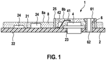
- a circuit board 2 which has a first side 21 and a second side 22 facing away from it, is equipped with electronic components 24 and a contact assembly 42.
- the electronic components 24 can, for example, form an electronic control circuit and can be applied to the circuit board 2 and contacted in standard processes. This includes, for example, gluing and bonding of bare-die components as well as the assembly and reflow soldering of housed electronic components.
- the circuit board 2 can be a conventional FR4 circuit board made of glass fiber reinforced epoxy resin with in copper conductor tracks arranged in one or more layers.
- the circuit board 2 is provided with an opening 23 which extends from the first side 21 to the second side 22.
- the breakthrough 23 can be introduced into the circuit board 2, for example by milling or drilling.
- the circuit board has, for example, a further recess 29 designed as a bore.
- Electrical connecting means 41 can be arranged on the contact assembly 42, which can be designed, for example, as a stamped grid part, flexible circuit board or cable.
- the electronic components 24 and the contact assembly 42 with the electrical connecting means 41 can be soldered, for example, in a soldering oven with contact surfaces on the first side 21 of the circuit board 2.
- a frame part 25 can be arranged on the first side 21 of the circuit board, which surrounds the opening 23 and the contact assembly 41.
- the frame part can be made from metal or plastic or using a viscous and fast-hardening adhesive application.
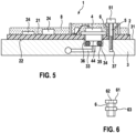
- a metallic bushing 6 is pressed into the recess 29.
- the socket 6 has an end face 61 which faces away from the first side 21 of the circuit board 2 and from which a receiving opening 62 extends to the second side 22 of the circuit board 2.
- the socket 6 can also be soldered to a contact surface on the first side of the circuit board 2.
- the socket 6 can have a circumferential collar 63 for contact with the first side 21 of the circuit board 2.
- the circuit board 2 can be in the in Fig. 2 or Fig. 3 shown state can be soldered in the soldering oven.
- a sensor element 4 for example a pressure sensor element 4a
- the sensor element 4 can have a circumferential collar 43, which comes into contact with the edge of the opening 23 on the first side 21 of the circuit board 2.
- the sensor element 4 is pushed under the flexible connecting means 41, which can be raised for this purpose.
- the sensor element 4 preferably completely covers the breakthrough 23 in order to avoid the sealing compound running through the breakthrough 23 when applying the casting compound.
- the electrical contact between the sensor element 4 and the connecting means 4 can be made after inserting the sensor element 4, for example by laser welding or with a soldering tip or another selective soldering process. In the same way, at least one or more sensor elements 4 can be mounted on the circuit board 2.
- a potting compound 8 is applied to the first side 21 of the circuit board.
- the casting compound 8 can be filled in a first filling area 8a outside the frame part 25 and at the same time in a second filling area 8b with a larger filling height within the frame part 25.
- the potting compound 8 can be applied with a dispensing head. Drainage of the casting compound 8 from the first filling area 8a can be prevented with a circumferential dam, not shown, arranged on the first side.
- the potting compound 8 completely covers the electronic components 24, the contact assembly with the connecting means 41 and the sensor element 4 on the first side 21 of the circuit board 2.
- the casting compound 8 can then be hardened.
- no injection molding or molding tools are required.
- thermoset in particular an epoxy resin
- CTE Coefficient of Thermal Expansion
- the circuit board with a CTE of 18 ppm/K
- the sensor element with a steel housing and a CTE of 20 ppm/K
- the electronic components 24 and the frame part 25 and the thermoset contact assembly 42 with a CTE between 10 and 40 ppm/K
- the bushing 6 made of steel with a CTE of 20 ppm/K.
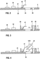
- the electronic module 1 can, for example, as in Fig. 5 shown, with the second side 22 of the circuit board 2 being placed flat on a flat surface 31 of a hydraulic plate 3 of a motor vehicle transmission.
- the hydraulic plate 3 can have a medium channel 33, for example a hydraulic channel, opening on the surface 31 of the hydraulic plate 3.
- the electronic module 1 is mounted on the hydraulic plate in such a way that the medium channel 33 is in fluid communication with the sensor element 4.
- the medium channel 33 can have a section designed as a depression 36, the bottom of which has a horizontal shoulder 34, on which a sealing ring 35 is arranged, which is pressed between a section 44 of the sensor element 4 projecting into the opening 23 and the shoulder 34.
- the electronic module 1 can be screwed into threaded holes 37 in the hydraulic plate 3 by means of screwable connecting means 5, the screw heads 51 of which are supported on the end face 61 of the socket 6.
- the screwable ones Connecting means 5 press the entire electronic module 1 against the hydraulic plate 3.
- a fluid pressure prevailing in the medium channel 33 acts on the sensor element 4 designed as a pressure sensor element 4a. Since the sensor element 4 is firmly installed on the electronic module 1 via the casting compound 8, the force transmitted to the electronic module 1 is advantageously absorbed by the screwed-on sockets 6 .
Landscapes
- Engineering & Computer Science (AREA)
- Microelectronics & Electronic Packaging (AREA)
- Physics & Mathematics (AREA)
- General Physics & Mathematics (AREA)
- Chemical & Material Sciences (AREA)
- Analytical Chemistry (AREA)
- Manufacturing & Machinery (AREA)
- Measuring Fluid Pressure (AREA)
Description
In der Kraftfahrzeugtechnik werden Elektronikmodule zur Ansteuerung eines Getriebes am oder im Getriebe verbaut. Die Elektronikmodule können beispielsweise als Getriebesteuermodule ausgelegt sein und außer einer auf einer Leiterplatte angeordneten Steuerschaltung beispielsweise zusätzlich noch Steckerteile, Sensoren und Kontaktierungsschnittstellen zu Aktuatoren aufweisen. Die elektronische Steuerschaltung und muss vor dem aggressiven Getriebefluid geschützt werden. Zu diesem Zweck werden auch Vergussmassen eingesetzt, die auf die Leiterplatte zum Schutz der elektronischen Steuerschaltung aufgebracht wird.In automotive technology, electronic modules are installed on or in the transmission to control a transmission. The electronic modules can be designed, for example, as transmission control modules and, in addition to a control circuit arranged on a circuit board, can also have plug parts, sensors and contact interfaces to actuators. The electronic control circuit must be protected from the aggressive transmission fluid. For this purpose, potting compounds are also used, which are applied to the circuit board to protect the electronic control circuit.
So ist beispielsweise aus der der
Weiterhin ist beispielsweise aus der
Ferner ist aus der
Aus der
Aus der
Weitere Elektronikmodule, die Leiterplatten mit darauf angeordneten und von einer Vergussmasse abgedeckten elektronischen Bauelementen aufweisen, sind aus der
Die Erfindung betrifft ein Elektronikmodul, insbesondere ein Steuermodul oder ein Sensormodul für ein Getriebe, mit einer Leiterplatte, welche eine erste Seite und eine davon abgewandte zweite Seite aufweist, mit auf der ersten Seite angeordneten elektronischen Bauelementen und mit einer auf der ersten Seite angeordneten Vergussmasse, welche die elektronischen Bauelemente abdeckt, wobei die Leiterplatte einen die erste Seite mit der zweiten Seite verbindenden Durchbruch aufweist und ein den Durchbruch abdeckendes Sensorelement an der ersten Seite der Leiterplatte angeordnet ist. Erfindungsgemäß wird vorgeschlagen, dass eine Buchse zur Aufnahme eines schraubbaren Verbindungsmittels an der Leiterplatte angeordnet ist, wobei die Buchse von der auf die ersten Seite der Leiterplatte aufgetragenen Vergussmasse umlaufend flankiert ist und eine nicht mit der Vergussmasse abgedeckte Stirnseite aufweist, von der sich eine Aufnahmeöffnung bis zu der zweiten Seite der Leiterplatte erstreckt.The invention relates to an electronic module, in particular a control module or a sensor module for a transmission, with a circuit board which has a first side and a second side facing away from it, with circuit boards arranged on the first side electronic components and with a potting compound arranged on the first side, which covers the electronic components, the circuit board having an opening connecting the first side to the second side and a sensor element covering the opening being arranged on the first side of the circuit board. According to the invention, it is proposed that a socket for receiving a screwable connecting means is arranged on the circuit board, the socket being flanked all around by the potting compound applied to the first side of the circuit board and having an end face not covered with the potting compound, from which a receiving opening extends extends to the second side of the circuit board.
Weiterhin betrifft die Erfindung eine Kombination eines derartigen Elektronikmoduls mit einer Hydraulikplatte, wobei das Elektronikmodul mit der zweiten Seite der Leiterplatte an einer Oberfläche der Hydraulikplatte flach anliegt und die Hydraulikplatte einen an der Oberfläche mündenden Mediumkanal aufweist, wobei der Mediumkanal mit dem Sensorelement in einer Fluidverbindung steht.Furthermore, the invention relates to a combination of such an electronic module with a hydraulic plate, wherein the electronic module lies flat with the second side of the circuit board on a surface of the hydraulic plate and the hydraulic plate has a medium channel opening on the surface, the medium channel being in fluid connection with the sensor element .
Vorteilhaft kann bei dem erfindungsgemäßen Elektronikmodul die Lage eines Sensorelementes in dem Elektronikmodul ohne großen Aufwand geändert und an das jeweilige Anforderungsprofil angepasst werden. Bei notwendigen Designänderungen der Position des Sensorelementes an dem Elektronikmodul kann diese Änderung daher in sehr kurzer Zeit umgesetzt werden. Bei einer Änderung des Designs muss vorteilhaft nur das Leiterplatten-Layout in Hinblick auf die Lage des Durchbruchs und der elektrischen Anschlüsse des Sensorelementes angepasst werden. Vorteilhaft ist kein separater Kunststoffträger zur Anordnung des Sensorelements erforderlich und die Kosten für einen derartigen Kunststoffträger entfallen. Ebenso entfallen die mit der unterschiedlichen Wärmeausdehnung von Kunststoffträger und Leiterplatte verbundenen Schwierigkeiten. Das Sensorelement, beispielsweise ein Drucksensorelement, wird in einfacher Weise an der ersten Seite der Leiterplatte derart angeordnet, dass es dort einen zur Zuführung des Messmediums vorgesehenen Durchbruch abdeckt. Die Leiterplatte wird durch den Einbau des Sensorelementes und bei einer Belastung des Sensorelementes mit hydraulischem Druck mechanisch nicht belastet, wodurch die Gefahr einer Beschädigung vermieden wird.Advantageously, in the electronic module according to the invention, the position of a sensor element in the electronic module can be changed without great effort and adapted to the respective requirement profile. If design changes to the position of the sensor element on the electronic module are necessary, this change can therefore be implemented in a very short time. If the design is changed, advantageously only the circuit board layout needs to be adjusted with regard to the position of the opening and the electrical connections of the sensor element. Advantageously, no separate plastic carrier is required for arranging the sensor element and the costs for such a plastic carrier are eliminated. The difficulties associated with the different thermal expansion of the plastic carrier and the circuit board are also eliminated. The sensor element, for example a pressure sensor element, is arranged in a simple manner on the first side of the circuit board in such a way that it covers an opening provided for supplying the measuring medium. The printed circuit board is not subjected to mechanical stress due to the installation of the sensor element and when the sensor element is loaded with hydraulic pressure, thereby avoiding the risk of damage.
Der Einbau des Sensorelements kann vor oder nach dem Bestücken und Auflöten von elektronischen Bauelementen auf die Leiterplatte erfolgen. Im letzteren Fall kann bei hohen Löttemperaturen eines Lötofens, die beispielsweise zur Verlötung von bleifreien Loten notwendig sind, vorteilhaft erreicht werden, dass die Ofentemperatur nicht zum Aufschmelzen der Lötverbindungen im Sensorelement selbst führt.The sensor element can be installed before or after the assembly and soldering of electronic components onto the circuit board. In the latter case, at high soldering temperatures in a soldering oven, which are necessary, for example, for soldering lead-free solders, it can advantageously be achieved that the oven temperature does not lead to the solder connections in the sensor element itself melting.
Zur mechanischen Festlegung des elektronischen Elektronikmoduls an einem Getriebebauteil ist erfindungsgemäß wenigstens eine Buchse zur Aufnahme eines schraubbaren Verbindungsmittels an der Leiterplatte angeordnet, wobei die Buchse von der auf der ersten Seite der Leiterplatte aufgetragenen Vergussmasse umlaufend flankiert ist und eine nicht mit der Vergussmasse abgedeckte Stirnseite aufweist, von der sich eine Aufnahmeöffnung bis zu der zweiten Seite der Leiterplatte erstreckt. Dadurch wird vorteilhaft erreicht, dass ein in die Aufnahmeöffnung eingeführte schraubbares Verbindungsmittel beim Festziehen die Spannkraft auf die Stirnseite der Buchse überträgt. Die Buchse wiederum kann sich auf der zweiten Seite der Leiterplatte direkt am Getriebebauteil abstützen, so dass eine Krafteinleitung auf die Leiterplatte beim Festziehen der Schraube vermieden wird. Beim Anliegen eines Hydraulikdrucks erfährt das Sensorelement eine Druckkraft. Da das Sensorelement fest an dem elektronischen Elektronikmodul verbaut ist, wird diese Kraft vorteilhaft von den angeschraubten Buchsen aufgenommen. Die Leiterplatte erfährt hierbei vorteilhaft keine unzulässig hohen Press- oder Zugkräfte. Natürlich können auch mehrere Buchsen an dem Elektronikmodul vorgesehen sein.In order to mechanically fix the electronic module to a transmission component, according to the invention at least one socket for receiving a screwable connecting means is arranged on the circuit board, the socket being flanked all around by the casting compound applied to the first side of the circuit board and having an end face not covered with the casting compound, from which a receiving opening extends to the second side of the circuit board. This advantageously ensures that a screwable connecting means inserted into the receiving opening transfers the clamping force to the end face of the socket when tightened. The socket, in turn, can be supported directly on the gear component on the second side of the circuit board, so that the introduction of force to the circuit board when tightening the screw is avoided. When hydraulic pressure is applied, the sensor element experiences a pressure force. Since the sensor element is permanently installed on the electronic module, this force is advantageously absorbed by the screwed-on sockets. The circuit board advantageously does not experience any unacceptably high pressing or tensile forces. Of course, several sockets can also be provided on the electronic module.
Vorteilhafte Ausgestaltungen und Weiterbildungen der Erfindung werden durch die in den abhängigen Ansprüchen enthaltenen Merkmale ermöglicht.Advantageous refinements and further developments of the invention are made possible by the features contained in the dependent claims.
Vorteilhaft kann das Sensorelement den Durchbruch vollständig abdecken und auf der ersten Seite der Leiterplatte mit der Vergussmasse abgedeckt sein, wodurch das Sensorelement mechanisch stabil an dem Elektronikmodul angeordnet und vor dem aggressiven Getriebefluid und darin enthaltenen Metallspänen ausreichend geschützt ist. Vorteilhaft sind zur Festlegung des Sensorelementes an der Leiterplatte keine Befestigungsschrauben oder Nieten erforderlich, die Flächen und Freiraum auf der Leiterplatte benötigen würden. Durch die Verwendung einer Vergussmasse, beispielsweise einen duroplastischen Werkstoffs, zur mechanischen Festlegung des Sensorelements tritt bei Temperaturschwankungen und Alterung des Elektronikmoduls keine Relaxation auf, so dass sich die Lage des Sensorelementes an dem Elektronikmodul bei Druckbelastung und Alterung des Elektronikmoduls vorteilhaft nicht verändert.Advantageously, the sensor element can completely cover the breakthrough and be covered with the casting compound on the first side of the circuit board, whereby the sensor element is arranged in a mechanically stable manner on the electronic module and is adequately protected from the aggressive transmission fluid and metal chips contained therein. Advantageously, no fastening screws or rivets are required to secure the sensor element to the circuit board, which would require areas and free space on the circuit board. By using a casting compound, for example a thermoset material, to mechanically fix the sensor element, temperature fluctuations and aging of the electronic module occur no relaxation occurs, so that the position of the sensor element on the electronic module advantageously does not change under pressure load and aging of the electronic module.
Vorteilhaft können elektrische Verbindungsmittel, welche das Sensorelement mit der Leiterplatte elektrisch verbinden, in die Vergussmasse eingebettet sein. Die elektrischen Verbindungsmittel zwischen dem Sensorelement und der Leiterplatte können beispielsweise mittels Kabelverbindungen, Stanzgittern oder flexiblen Leiterplatten (FPC = Flexible Printed Circuit) aus Polyimid oder FR4-Material erfolgen. Durch die Einbettung in die Vergussmasse sind die elektrischen Verbindungsmittel gegen Kurzschlüsse, welche durch Metallspäne im Getriebefluid entstehen können, und gegen chemische Belastungen geschützt.Electrical connecting means, which electrically connect the sensor element to the circuit board, can advantageously be embedded in the casting compound. The electrical connection means between the sensor element and the circuit board can be made, for example, by means of cable connections, stamped grids or flexible printed circuit boards (FPC = Flexible Printed Circuit) made of polyimide or FR4 material. By embedding in the casting compound, the electrical connecting means are protected against short circuits, which can be caused by metal chips in the transmission fluid, and against chemical stress.
Vorteilhaft kann das Sensorelement in den Durchbruch eingesetzt sein, wodurch ein relaxationsfreier Einbau gelingt, der ohne Federn auskommt und Druck- sowie Zugbelastungen der Leiterplatte minimiert. Das Sensorelement kann zu diesem Zweck vorteilhaft einen umlaufenden Kragen aufweisen, der am Rand des Durchbruchs auf der ersten Seite der Leiterplatte aufliegt. Vorteilhaft kann das Sensorelement bei einem der letzten Herstellungsschritte des Elektronikmoduls an der Leiterplatte durch einfaches Einsetzen montiert und gleichzeitig elektrisch kontaktiert werden.The sensor element can advantageously be inserted into the opening, which results in a relaxation-free installation that does not require springs and minimizes pressure and tensile loads on the circuit board. For this purpose, the sensor element can advantageously have a circumferential collar which rests on the edge of the opening on the first side of the circuit board. Advantageously, the sensor element can be mounted on the circuit board by simply inserting it in one of the last manufacturing steps of the electronic module and can be electrically contacted at the same time.
Falls das an der ersten Seite der Leiterplatte angeordnete Sensorelement eine relativ große Bauhöhe aufweist, kann dort vorteilhaft ein das Sensorelement umgebendes Rahmenteil angeordnet sein, innerhalb dessen die Vergussmasse mit einer größeren Füllhöhe als in einem Bereich außerhalb des Rahmenteils auf die ersten Seite der Leiterplatte aufgetragen ist. Unter Füllhöhe wird in diesem Zusammenhang die Materialstärke beziehungsweise Dicke der Vergussmasse in einer Richtung senkrecht zur ersten Seite der Leiterplatte verstanden.If the sensor element arranged on the first side of the circuit board has a relatively large overall height, a frame part surrounding the sensor element can advantageously be arranged there, within which the potting compound is applied to the first side of the circuit board with a greater filling height than in an area outside the frame part . In this context, filling height is understood to mean the material thickness or thickness of the potting compound in a direction perpendicular to the first side of the circuit board.
Weiterhin vorteilhaft ist eine Kombination des beschriebenen Elektronikmoduls mit einer Hydraulikplatte, wobei das Elektronikmodul mit der zweiten Seite der Leiterplatte an einer Oberfläche der Hydraulikplatte flach anliegt und die Hydraulikplatte einen an der Oberfläche der Hydraulikplatte mündenden Mediumkanal aufweist, wobei der Mediumkanal mit dem Sensorelement in einer Fluidverbindung steht. Das Medium kann ein Gas oder eine Flüssigkeit und insbesondere Getriebefluid sein.A combination of the electronic module described with a hydraulic plate is also advantageous, wherein the electronic module lies flat with the second side of the circuit board on a surface of the hydraulic plate and the hydraulic plate has a medium channel opening on the surface of the hydraulic plate, the medium channel being in fluid connection with the sensor element stands. The medium can be a gas or a liquid and in particular transmission fluid.
Zur Abdichtung des Mediumkanals kann in einfacher Weise vorteilhaft vorgesehen sein, dass der Mediumkanal beispielsweise einen Absatz aufweist, an dem ein Dichtungsring angeordnet ist, der zwischen einem in den Durchbruch hineinragenden Abschnitt des Sensorelements und dem Absatz eingepresst ist.To seal the medium channel, it can be advantageously provided in a simple manner that the medium channel has, for example, a shoulder on which a sealing ring is arranged, which is pressed between a section of the sensor element projecting into the opening and the shoulder.
Es zeigen:
-
Fig. 1 einen Querschnitt durch ein Ausführungsbeispiel eines erfindungsgemäßen Elektronikmoduls, -
Fig. 2 bis Fig. 4 einzelne Fertigungsschritte bei der Herstellung des Elektronikmoduls, -
Fig. 5 einen Querschnitt durch eine Ausführungsbeispiel einer Kombination eines Elektronikmoduls mit einer Hydraulikplatte -
Fig. 6 eine Ausführungsform einer an dem Elektronikmodul verbauten Schraubenbuchse.
-
Fig. 1 a cross section through an exemplary embodiment of an electronic module according to the invention, -
Fig. 2 to Fig. 4 individual manufacturing steps in the manufacture of the electronic module, -
Fig. 5 a cross section through an exemplary embodiment of a combination of an electronic module with a hydraulic plate -
Fig. 6 an embodiment of a screw socket installed on the electronic module.
Bei dem Elektronikmodul kann es sich beispielsweise um ein Steuermodul zur Ansteuerung eines Aggregats oder um ein Sensormodul mit mehreren Sensoren handeln. Insbesondere handelt es ich um ein Getriebesteuermodul oder eine Sensormodul für ein Getriebe.The electronic module can be, for example, a control module for controlling a unit or a sensor module with several sensors. In particular, it is a transmission control module or a sensor module for a transmission.
Der Aufbau eines in
Zunächst wird, wie in
Wie in
Wie in
Schließlich wird, wie in
Das Elektronikmodul 1 kann beispielsweise, wie in
Ein in dem Mediumkanal 33 herrschender Fluiddruck wirkt im Betrieb auf das als Drucksensorelement 4a ausgebildete Sensorelement 4. Da das Sensorelement 4 über die Vergussmasse 8 fest an dem Elektronikmodul 1 verbaut ist, wird die auf das Elektronikmodul 1 übertragene Kraft vorteilhaft von den angeschraubten Buchsen 6 aufgenommen.During operation, a fluid pressure prevailing in the
Claims (9)
- Electronics module (1), in particular control module or sensor module for a motor vehicle transmission, comprising a printed circuit board (2) which has a first side (21) and a second side (22) which is averted from said first side, comprising electronic components (24) which are arranged on the first side (21) and comprising a potting compound (8) which is arranged on the first side (21) and covers the electronic components (24), wherein the printed circuit board (2) has an aperture (23) which connects the first side (21) to the second side (22), and a sensor element (4), which covers the aperture (23), is arranged on the first side (21) of the printed circuit board (2), characterized in that a bush (6) for receiving a screwable connecting means (5) is arranged on the printed circuit board (2), wherein the bush (6) is flanked in a circumferential manner by the potting compound (8), which is applied to the first side (21) of the printed circuit board (2), and has an end side (61) which is not covered by the potting compound (8) and from which a receiving opening (62) extends as far as the second side (22) of the printed circuit board (2) .
- Electronics module according to Claim 1, characterized in that the sensor element (4) completely covers the aperture (23), and in that the sensor element (4) is covered by the potting compound (8) on the first side (21) of the printed circuit board (2).
- Electronics module according to Claim 1 or 2, characterized in that electrical connecting means (41), which electrically connect the sensor element (4) to the printed circuit board (2), are embedded into the potting compound (8).
- Electronics module according to one of the preceding claims, characterized in that the sensor element (4) is inserted into the aperture (23).
- Electronics module according to one of the preceding claims, characterized in that the sensor element (4) has a circumferential collar (43) which rests on the first side (21) of the printed circuit board (2) at the edge of the aperture (23).
- Electronics module according to one of the preceding claims, characterized in that the sensor element (4) is a pressure sensor element (4a).
- Electronics module according to one of the preceding claims, characterized in that a frame part (25), which surrounds the sensor element (4) and within which the potting compound (8) is applied to the first side (21) of the printed circuit board (2) with a greater filling level than in a region outside the frame part (25), is arranged on the first side (21) of the printed circuit board.
- Combination of an electronics module (1) according to one of the preceding Claims 1 to 7 with a hydraulic plate (3), wherein the electronics module (1), by way of the second side (22) of the printed circuit board (2), bears flat against a surface (31) of the hydraulic plate (3) and the hydraulic plate (3) has a medium channel (33) which issues at the surface (31) of the hydraulic plate (3), wherein the medium channel (33) is fluidically connected to the sensor element (4).
- Combination of an electronics module according to Claim 8, characterized in that the medium channel (33) has a projection (34) on which a sealing ring (35) is arranged, said sealing ring being pressed in between a section of the sensor element (4) which protrudes into the aperture (23) and the projection (34).
Applications Claiming Priority (2)
| Application Number | Priority Date | Filing Date | Title |
|---|---|---|---|
| DE102017211513.0A DE102017211513A1 (en) | 2017-07-06 | 2017-07-06 | Electronic module and combination of an electronic module with a hydraulic plate |
| PCT/EP2018/062389 WO2019007573A1 (en) | 2017-07-06 | 2018-05-14 | ELECTRONIC MODULE AND COMBINATION OF AN ELECTRONIC MODULE WITH A HYDRAULIC PLATE |
Publications (2)
| Publication Number | Publication Date |
|---|---|
| EP3649835A1 EP3649835A1 (en) | 2020-05-13 |
| EP3649835B1 true EP3649835B1 (en) | 2023-12-20 |
Family
ID=62217955
Family Applications (1)
| Application Number | Title | Priority Date | Filing Date |
|---|---|---|---|
| EP18726094.8A Active EP3649835B1 (en) | 2017-07-06 | 2018-05-14 | Electronic module and combination of an electronic module and a hydraulic plate |
Country Status (6)
| Country | Link |
|---|---|
| US (1) | US11166391B2 (en) |
| EP (1) | EP3649835B1 (en) |
| KR (1) | KR20200024208A (en) |
| CN (1) | CN110809911B (en) |
| DE (1) | DE102017211513A1 (en) |
| WO (1) | WO2019007573A1 (en) |
Families Citing this family (7)
| Publication number | Priority date | Publication date | Assignee | Title |
|---|---|---|---|---|
| JP6565867B2 (en) * | 2016-10-28 | 2019-08-28 | 株式会社デンソー | Air physical quantity sensor |
| DE102019132570A1 (en) * | 2019-12-01 | 2021-06-02 | Danfoss Silicon Power Gmbh | Power module with a pressure sensor |
| DE102020212585A1 (en) * | 2020-10-06 | 2022-04-07 | Robert Bosch Gesellschaft mit beschränkter Haftung | electronics module |
| DE102021212582A1 (en) | 2021-11-09 | 2023-05-11 | Robert Bosch Gesellschaft mit beschränkter Haftung | Sensor arrangement, fuel cell system with a sensor arrangement and method for producing a sensor arrangement |
| DE102022101839A1 (en) * | 2022-01-27 | 2023-07-27 | Schaeffler Technologies AG & Co. KG | Electrical and dirt-tight connection between two installation spaces |
| DE102022120682A1 (en) * | 2022-08-16 | 2024-02-22 | Kyocera Avx Components (Werne) Gmbh | Embedding a circuit board in potting compound |
| DE102022212420A1 (en) | 2022-11-22 | 2024-05-23 | Robert Bosch Gesellschaft mit beschränkter Haftung | Electronic module |
Citations (3)
| Publication number | Priority date | Publication date | Assignee | Title |
|---|---|---|---|---|
| DE102005002813A1 (en) * | 2005-01-20 | 2006-08-10 | Robert Bosch Gmbh | control module |
| WO2014146614A1 (en) * | 2013-03-22 | 2014-09-25 | Dow Corning (China) Holding Co., Ltd. | Sectioned potting in power converters |
| EP2906024A1 (en) * | 2014-01-15 | 2015-08-12 | Hitachi Ltd. | Communication device and production method therefor |
Family Cites Families (15)
| Publication number | Priority date | Publication date | Assignee | Title |
|---|---|---|---|---|
| DE19834212A1 (en) * | 1998-07-29 | 2000-02-10 | Siemens Ag | Control device in a motor vehicle and pressure sensor used by this |
| EP1108163B1 (en) * | 1998-08-24 | 2002-03-06 | Siemens Aktiengesellschaft | Control device in a motor vehicle |
| DE10101091A1 (en) * | 2001-01-11 | 2002-07-25 | Siemens Ag | Hydraulic motor vehicle transmission control device with plastic hydraulic distributor plate and integrated conductors and method for its production |
| JP4585828B2 (en) * | 2004-10-06 | 2010-11-24 | 日立オートモティブシステムズ株式会社 | Control device and manufacturing method thereof |
| EP1950806A1 (en) | 2006-11-30 | 2008-07-30 | Matsushita Electric Industrial Co., Ltd. | Interposer with built-in passive part |
| US7550828B2 (en) | 2007-01-03 | 2009-06-23 | Stats Chippac, Inc. | Leadframe package for MEMS microphone assembly |
| US8898690B2 (en) * | 2007-10-30 | 2014-11-25 | BBS Media | Apparatus and method for managing media content |
| JP4941509B2 (en) * | 2008-10-20 | 2012-05-30 | 株式会社デンソー | Electronic control device |
| DE102011085629A1 (en) | 2011-11-02 | 2013-05-02 | Robert Bosch Gmbh | Electronic module for operation in the gearbox |
| DE102012222180B4 (en) * | 2012-12-04 | 2024-07-18 | Robert Bosch Gmbh | Super-flat transmission control module |
| DE102013205155B4 (en) | 2013-03-22 | 2023-05-04 | Robert Bosch Gmbh | Device for fastening a pressure sensor to a carrier plate provided with a pressure channel |
| DE102013227003A1 (en) * | 2013-12-20 | 2015-06-25 | Robert Bosch Gmbh | Electronic control module and method for manufacturing an electronic control module |
| DE102015209191A1 (en) * | 2015-02-10 | 2016-08-11 | Conti Temic Microelectronic Gmbh | Mechatronic component and method for its production |
| DE102015205445A1 (en) | 2015-03-25 | 2016-09-29 | Robert Bosch Gmbh | Transmission control unit for a transmission of a vehicle |
| DE102015221149A1 (en) * | 2015-10-29 | 2017-05-04 | Robert Bosch Gmbh | Control device for a transmission control of a motor vehicle |
-
2017
- 2017-07-06 DE DE102017211513.0A patent/DE102017211513A1/en not_active Withdrawn
-
2018
- 2018-05-14 EP EP18726094.8A patent/EP3649835B1/en active Active
- 2018-05-14 CN CN201880044788.2A patent/CN110809911B/en active Active
- 2018-05-14 US US16/627,975 patent/US11166391B2/en not_active Expired - Fee Related
- 2018-05-14 WO PCT/EP2018/062389 patent/WO2019007573A1/en not_active Ceased
- 2018-05-14 KR KR1020207000194A patent/KR20200024208A/en not_active Withdrawn
Patent Citations (3)
| Publication number | Priority date | Publication date | Assignee | Title |
|---|---|---|---|---|
| DE102005002813A1 (en) * | 2005-01-20 | 2006-08-10 | Robert Bosch Gmbh | control module |
| WO2014146614A1 (en) * | 2013-03-22 | 2014-09-25 | Dow Corning (China) Holding Co., Ltd. | Sectioned potting in power converters |
| EP2906024A1 (en) * | 2014-01-15 | 2015-08-12 | Hitachi Ltd. | Communication device and production method therefor |
Also Published As
| Publication number | Publication date |
|---|---|
| CN110809911B (en) | 2022-09-30 |
| CN110809911A (en) | 2020-02-18 |
| US20200221591A1 (en) | 2020-07-09 |
| KR20200024208A (en) | 2020-03-06 |
| DE102017211513A1 (en) | 2019-01-10 |
| US11166391B2 (en) | 2021-11-02 |
| WO2019007573A1 (en) | 2019-01-10 |
| EP3649835A1 (en) | 2020-05-13 |
Similar Documents
| Publication | Publication Date | Title |
|---|---|---|
| EP3649835B1 (en) | Electronic module and combination of an electronic module and a hydraulic plate | |
| EP1831055B1 (en) | Control module | |
| EP3085211B1 (en) | Electronic control module and method for producing an electronic control module | |
| EP1842407B1 (en) | Control module | |
| EP2225125B1 (en) | Controller housing | |
| EP3381246B1 (en) | Electronic module and method for producing an electronic module having a fluid-tight housing | |
| WO2013068146A1 (en) | Electronic module for a control unit | |
| DE10051945C1 (en) | Sealed chamber for accommodating motor vehicle electronic components has recess sealed against oil and/or fuel by adhesive completely enclosing it, sticking circuit board to base part | |
| EP3292593B1 (en) | Electrical connection arrangement | |
| EP3225085B1 (en) | Electronics module, in particular for a motor vehicle transmission control unit, comprising press contact sandwich module technology | |
| WO2017060034A1 (en) | Electronic arrangement, combination, and method for installation of an electronic arrangement | |
| EP3574723B1 (en) | Method for mechanically connecting electronic components and corresponding arrangement of these electronic components | |
| WO2020043341A1 (en) | Electronic module and method for the production thereof | |
| DE102019201404A1 (en) | Electronics module | |
| EP3643147B1 (en) | Electronic module | |
| EP2609795B1 (en) | Method for populating a circuit board with a plurality of components and electrical circuit having a circuit board and a plurality of components mounted thereon | |
| WO2019162077A1 (en) | Press-fit connection | |
| EP3520585B1 (en) | Method for producing an electronic assembly, and electronic assembly, in particular for a transmission control module | |
| EP2288246B1 (en) | High-performance semiconductor and method for installing same | |
| EP3250010A1 (en) | Electronic control module and method for producing an electronic control module | |
| EP3284327B1 (en) | Electronics module for a transmission controller | |
| DE102020212585A1 (en) | electronics module | |
| EP3659410B1 (en) | Electrical assembly | |
| DE102015218171B4 (en) | Method of manufacturing an electronic component and electronic component | |
| DE102019217741A1 (en) | v Electronics module and method of making an electronics module |
Legal Events
| Date | Code | Title | Description |
|---|---|---|---|
| STAA | Information on the status of an ep patent application or granted ep patent |
Free format text: STATUS: UNKNOWN |
|
| STAA | Information on the status of an ep patent application or granted ep patent |
Free format text: STATUS: THE INTERNATIONAL PUBLICATION HAS BEEN MADE |
|
| PUAI | Public reference made under article 153(3) epc to a published international application that has entered the european phase |
Free format text: ORIGINAL CODE: 0009012 |
|
| STAA | Information on the status of an ep patent application or granted ep patent |
Free format text: STATUS: REQUEST FOR EXAMINATION WAS MADE |
|
| 17P | Request for examination filed |
Effective date: 20200206 |
|
| AK | Designated contracting states |
Kind code of ref document: A1 Designated state(s): AL AT BE BG CH CY CZ DE DK EE ES FI FR GB GR HR HU IE IS IT LI LT LU LV MC MK MT NL NO PL PT RO RS SE SI SK SM TR |
|
| AX | Request for extension of the european patent |
Extension state: BA ME |
|
| DAV | Request for validation of the european patent (deleted) | ||
| DAX | Request for extension of the european patent (deleted) | ||
| STAA | Information on the status of an ep patent application or granted ep patent |
Free format text: STATUS: EXAMINATION IS IN PROGRESS |
|
| 17Q | First examination report despatched |
Effective date: 20220202 |
|
| GRAJ | Information related to disapproval of communication of intention to grant by the applicant or resumption of examination proceedings by the epo deleted |
Free format text: ORIGINAL CODE: EPIDOSDIGR1 |
|
| GRAP | Despatch of communication of intention to grant a patent |
Free format text: ORIGINAL CODE: EPIDOSNIGR1 |
|
| GRAP | Despatch of communication of intention to grant a patent |
Free format text: ORIGINAL CODE: EPIDOSNIGR1 |
|
| STAA | Information on the status of an ep patent application or granted ep patent |
Free format text: STATUS: GRANT OF PATENT IS INTENDED |
|
| INTG | Intention to grant announced |
Effective date: 20231005 |
|
| GRAS | Grant fee paid |
Free format text: ORIGINAL CODE: EPIDOSNIGR3 |
|
| GRAA | (expected) grant |
Free format text: ORIGINAL CODE: 0009210 |
|
| STAA | Information on the status of an ep patent application or granted ep patent |
Free format text: STATUS: THE PATENT HAS BEEN GRANTED |
|
| AK | Designated contracting states |
Kind code of ref document: B1 Designated state(s): AL AT BE BG CH CY CZ DE DK EE ES FI FR GB GR HR HU IE IS IT LI LT LU LV MC MK MT NL NO PL PT RO RS SE SI SK SM TR |
|
| REG | Reference to a national code |
Ref country code: GB Ref legal event code: FG4D Free format text: NOT ENGLISH |
|
| REG | Reference to a national code |
Ref country code: DE Ref legal event code: R096 Ref document number: 502018013842 Country of ref document: DE |
|
| REG | Reference to a national code |
Ref country code: CH Ref legal event code: EP |
|
| REG | Reference to a national code |
Ref country code: IE Ref legal event code: FG4D Free format text: LANGUAGE OF EP DOCUMENT: GERMAN |
|
| PG25 | Lapsed in a contracting state [announced via postgrant information from national office to epo] |
Ref country code: GR Free format text: LAPSE BECAUSE OF FAILURE TO SUBMIT A TRANSLATION OF THE DESCRIPTION OR TO PAY THE FEE WITHIN THE PRESCRIBED TIME-LIMIT Effective date: 20240321 |
|
| REG | Reference to a national code |
Ref country code: LT Ref legal event code: MG9D |
|
| PG25 | Lapsed in a contracting state [announced via postgrant information from national office to epo] |
Ref country code: LT Free format text: LAPSE BECAUSE OF FAILURE TO SUBMIT A TRANSLATION OF THE DESCRIPTION OR TO PAY THE FEE WITHIN THE PRESCRIBED TIME-LIMIT Effective date: 20231220 |
|
| REG | Reference to a national code |
Ref country code: NL Ref legal event code: MP Effective date: 20231220 |
|
| PG25 | Lapsed in a contracting state [announced via postgrant information from national office to epo] |
Ref country code: ES Free format text: LAPSE BECAUSE OF FAILURE TO SUBMIT A TRANSLATION OF THE DESCRIPTION OR TO PAY THE FEE WITHIN THE PRESCRIBED TIME-LIMIT Effective date: 20231220 |
|
| PG25 | Lapsed in a contracting state [announced via postgrant information from national office to epo] |
Ref country code: LT Free format text: LAPSE BECAUSE OF FAILURE TO SUBMIT A TRANSLATION OF THE DESCRIPTION OR TO PAY THE FEE WITHIN THE PRESCRIBED TIME-LIMIT Effective date: 20231220 Ref country code: GR Free format text: LAPSE BECAUSE OF FAILURE TO SUBMIT A TRANSLATION OF THE DESCRIPTION OR TO PAY THE FEE WITHIN THE PRESCRIBED TIME-LIMIT Effective date: 20240321 Ref country code: FI Free format text: LAPSE BECAUSE OF FAILURE TO SUBMIT A TRANSLATION OF THE DESCRIPTION OR TO PAY THE FEE WITHIN THE PRESCRIBED TIME-LIMIT Effective date: 20231220 Ref country code: ES Free format text: LAPSE BECAUSE OF FAILURE TO SUBMIT A TRANSLATION OF THE DESCRIPTION OR TO PAY THE FEE WITHIN THE PRESCRIBED TIME-LIMIT Effective date: 20231220 Ref country code: BG Free format text: LAPSE BECAUSE OF FAILURE TO SUBMIT A TRANSLATION OF THE DESCRIPTION OR TO PAY THE FEE WITHIN THE PRESCRIBED TIME-LIMIT Effective date: 20240320 |
|
| PG25 | Lapsed in a contracting state [announced via postgrant information from national office to epo] |
Ref country code: NL Free format text: LAPSE BECAUSE OF FAILURE TO SUBMIT A TRANSLATION OF THE DESCRIPTION OR TO PAY THE FEE WITHIN THE PRESCRIBED TIME-LIMIT Effective date: 20231220 |
|
| PG25 | Lapsed in a contracting state [announced via postgrant information from national office to epo] |
Ref country code: SE Free format text: LAPSE BECAUSE OF FAILURE TO SUBMIT A TRANSLATION OF THE DESCRIPTION OR TO PAY THE FEE WITHIN THE PRESCRIBED TIME-LIMIT Effective date: 20231220 Ref country code: RS Free format text: LAPSE BECAUSE OF FAILURE TO SUBMIT A TRANSLATION OF THE DESCRIPTION OR TO PAY THE FEE WITHIN THE PRESCRIBED TIME-LIMIT Effective date: 20231220 Ref country code: NO Free format text: LAPSE BECAUSE OF FAILURE TO SUBMIT A TRANSLATION OF THE DESCRIPTION OR TO PAY THE FEE WITHIN THE PRESCRIBED TIME-LIMIT Effective date: 20240320 Ref country code: NL Free format text: LAPSE BECAUSE OF FAILURE TO SUBMIT A TRANSLATION OF THE DESCRIPTION OR TO PAY THE FEE WITHIN THE PRESCRIBED TIME-LIMIT Effective date: 20231220 Ref country code: LV Free format text: LAPSE BECAUSE OF FAILURE TO SUBMIT A TRANSLATION OF THE DESCRIPTION OR TO PAY THE FEE WITHIN THE PRESCRIBED TIME-LIMIT Effective date: 20231220 Ref country code: HR Free format text: LAPSE BECAUSE OF FAILURE TO SUBMIT A TRANSLATION OF THE DESCRIPTION OR TO PAY THE FEE WITHIN THE PRESCRIBED TIME-LIMIT Effective date: 20231220 |
|
| PG25 | Lapsed in a contracting state [announced via postgrant information from national office to epo] |
Ref country code: IS Free format text: LAPSE BECAUSE OF FAILURE TO SUBMIT A TRANSLATION OF THE DESCRIPTION OR TO PAY THE FEE WITHIN THE PRESCRIBED TIME-LIMIT Effective date: 20240420 |
|
| PG25 | Lapsed in a contracting state [announced via postgrant information from national office to epo] |
Ref country code: CZ Free format text: LAPSE BECAUSE OF FAILURE TO SUBMIT A TRANSLATION OF THE DESCRIPTION OR TO PAY THE FEE WITHIN THE PRESCRIBED TIME-LIMIT Effective date: 20231220 |
|
| PG25 | Lapsed in a contracting state [announced via postgrant information from national office to epo] |
Ref country code: SK Free format text: LAPSE BECAUSE OF FAILURE TO SUBMIT A TRANSLATION OF THE DESCRIPTION OR TO PAY THE FEE WITHIN THE PRESCRIBED TIME-LIMIT Effective date: 20231220 |
|
| PG25 | Lapsed in a contracting state [announced via postgrant information from national office to epo] |
Ref country code: SM Free format text: LAPSE BECAUSE OF FAILURE TO SUBMIT A TRANSLATION OF THE DESCRIPTION OR TO PAY THE FEE WITHIN THE PRESCRIBED TIME-LIMIT Effective date: 20231220 Ref country code: SK Free format text: LAPSE BECAUSE OF FAILURE TO SUBMIT A TRANSLATION OF THE DESCRIPTION OR TO PAY THE FEE WITHIN THE PRESCRIBED TIME-LIMIT Effective date: 20231220 Ref country code: RO Free format text: LAPSE BECAUSE OF FAILURE TO SUBMIT A TRANSLATION OF THE DESCRIPTION OR TO PAY THE FEE WITHIN THE PRESCRIBED TIME-LIMIT Effective date: 20231220 Ref country code: IT Free format text: LAPSE BECAUSE OF FAILURE TO SUBMIT A TRANSLATION OF THE DESCRIPTION OR TO PAY THE FEE WITHIN THE PRESCRIBED TIME-LIMIT Effective date: 20231220 Ref country code: IS Free format text: LAPSE BECAUSE OF FAILURE TO SUBMIT A TRANSLATION OF THE DESCRIPTION OR TO PAY THE FEE WITHIN THE PRESCRIBED TIME-LIMIT Effective date: 20240420 Ref country code: EE Free format text: LAPSE BECAUSE OF FAILURE TO SUBMIT A TRANSLATION OF THE DESCRIPTION OR TO PAY THE FEE WITHIN THE PRESCRIBED TIME-LIMIT Effective date: 20231220 Ref country code: CZ Free format text: LAPSE BECAUSE OF FAILURE TO SUBMIT A TRANSLATION OF THE DESCRIPTION OR TO PAY THE FEE WITHIN THE PRESCRIBED TIME-LIMIT Effective date: 20231220 |
|
| PGFP | Annual fee paid to national office [announced via postgrant information from national office to epo] |
Ref country code: FR Payment date: 20240522 Year of fee payment: 7 |
|
| PG25 | Lapsed in a contracting state [announced via postgrant information from national office to epo] |
Ref country code: PL Free format text: LAPSE BECAUSE OF FAILURE TO SUBMIT A TRANSLATION OF THE DESCRIPTION OR TO PAY THE FEE WITHIN THE PRESCRIBED TIME-LIMIT Effective date: 20231220 Ref country code: PT Free format text: LAPSE BECAUSE OF FAILURE TO SUBMIT A TRANSLATION OF THE DESCRIPTION OR TO PAY THE FEE WITHIN THE PRESCRIBED TIME-LIMIT Effective date: 20240422 |
|
| PG25 | Lapsed in a contracting state [announced via postgrant information from national office to epo] |
Ref country code: PT Free format text: LAPSE BECAUSE OF FAILURE TO SUBMIT A TRANSLATION OF THE DESCRIPTION OR TO PAY THE FEE WITHIN THE PRESCRIBED TIME-LIMIT Effective date: 20240422 Ref country code: PL Free format text: LAPSE BECAUSE OF FAILURE TO SUBMIT A TRANSLATION OF THE DESCRIPTION OR TO PAY THE FEE WITHIN THE PRESCRIBED TIME-LIMIT Effective date: 20231220 |
|
| REG | Reference to a national code |
Ref country code: DE Ref legal event code: R097 Ref document number: 502018013842 Country of ref document: DE |
|
| PGFP | Annual fee paid to national office [announced via postgrant information from national office to epo] |
Ref country code: DE Payment date: 20240726 Year of fee payment: 7 |
|
| PG25 | Lapsed in a contracting state [announced via postgrant information from national office to epo] |
Ref country code: DK Free format text: LAPSE BECAUSE OF FAILURE TO SUBMIT A TRANSLATION OF THE DESCRIPTION OR TO PAY THE FEE WITHIN THE PRESCRIBED TIME-LIMIT Effective date: 20231220 |
|
| PLBE | No opposition filed within time limit |
Free format text: ORIGINAL CODE: 0009261 |
|
| STAA | Information on the status of an ep patent application or granted ep patent |
Free format text: STATUS: NO OPPOSITION FILED WITHIN TIME LIMIT |
|
| PG25 | Lapsed in a contracting state [announced via postgrant information from national office to epo] |
Ref country code: SI Free format text: LAPSE BECAUSE OF FAILURE TO SUBMIT A TRANSLATION OF THE DESCRIPTION OR TO PAY THE FEE WITHIN THE PRESCRIBED TIME-LIMIT Effective date: 20231220 |
|
| PG25 | Lapsed in a contracting state [announced via postgrant information from national office to epo] |
Ref country code: SI Free format text: LAPSE BECAUSE OF FAILURE TO SUBMIT A TRANSLATION OF THE DESCRIPTION OR TO PAY THE FEE WITHIN THE PRESCRIBED TIME-LIMIT Effective date: 20231220 Ref country code: DK Free format text: LAPSE BECAUSE OF FAILURE TO SUBMIT A TRANSLATION OF THE DESCRIPTION OR TO PAY THE FEE WITHIN THE PRESCRIBED TIME-LIMIT Effective date: 20231220 |
|
| 26N | No opposition filed |
Effective date: 20240923 |
|
| REG | Reference to a national code |
Ref country code: CH Ref legal event code: PL |
|
| PG25 | Lapsed in a contracting state [announced via postgrant information from national office to epo] |
Ref country code: MC Free format text: LAPSE BECAUSE OF FAILURE TO SUBMIT A TRANSLATION OF THE DESCRIPTION OR TO PAY THE FEE WITHIN THE PRESCRIBED TIME-LIMIT Effective date: 20231220 |
|
| PG25 | Lapsed in a contracting state [announced via postgrant information from national office to epo] |
Ref country code: LU Free format text: LAPSE BECAUSE OF NON-PAYMENT OF DUE FEES Effective date: 20240514 |
|
| GBPC | Gb: european patent ceased through non-payment of renewal fee |
Effective date: 20240514 |
|
| PG25 | Lapsed in a contracting state [announced via postgrant information from national office to epo] |
Ref country code: MC Free format text: LAPSE BECAUSE OF FAILURE TO SUBMIT A TRANSLATION OF THE DESCRIPTION OR TO PAY THE FEE WITHIN THE PRESCRIBED TIME-LIMIT Effective date: 20231220 Ref country code: LU Free format text: LAPSE BECAUSE OF NON-PAYMENT OF DUE FEES Effective date: 20240514 Ref country code: CH Free format text: LAPSE BECAUSE OF NON-PAYMENT OF DUE FEES Effective date: 20240531 |
|
| REG | Reference to a national code |
Ref country code: BE Ref legal event code: MM Effective date: 20240531 |
|
| PG25 | Lapsed in a contracting state [announced via postgrant information from national office to epo] |
Ref country code: IE Free format text: LAPSE BECAUSE OF NON-PAYMENT OF DUE FEES Effective date: 20240514 |
|
| PG25 | Lapsed in a contracting state [announced via postgrant information from national office to epo] |
Ref country code: BE Free format text: LAPSE BECAUSE OF NON-PAYMENT OF DUE FEES Effective date: 20240531 |
|
| PG25 | Lapsed in a contracting state [announced via postgrant information from national office to epo] |
Ref country code: GB Free format text: LAPSE BECAUSE OF NON-PAYMENT OF DUE FEES Effective date: 20240514 |
|
| REG | Reference to a national code |
Ref country code: AT Ref legal event code: MM01 Ref document number: 1643594 Country of ref document: AT Kind code of ref document: T Effective date: 20240514 |
|
| PG25 | Lapsed in a contracting state [announced via postgrant information from national office to epo] |
Ref country code: AT Free format text: LAPSE BECAUSE OF NON-PAYMENT OF DUE FEES Effective date: 20240514 |
|
| PG25 | Lapsed in a contracting state [announced via postgrant information from national office to epo] |
Ref country code: CY Free format text: LAPSE BECAUSE OF FAILURE TO SUBMIT A TRANSLATION OF THE DESCRIPTION OR TO PAY THE FEE WITHIN THE PRESCRIBED TIME-LIMIT; INVALID AB INITIO Effective date: 20180514 |
|
| PG25 | Lapsed in a contracting state [announced via postgrant information from national office to epo] |
Ref country code: HU Free format text: LAPSE BECAUSE OF FAILURE TO SUBMIT A TRANSLATION OF THE DESCRIPTION OR TO PAY THE FEE WITHIN THE PRESCRIBED TIME-LIMIT; INVALID AB INITIO Effective date: 20180514 |
|
| REG | Reference to a national code |
Ref country code: DE Ref legal event code: R119 Ref document number: 502018013842 Country of ref document: DE |
|
| PG25 | Lapsed in a contracting state [announced via postgrant information from national office to epo] |
Ref country code: DE Free format text: LAPSE BECAUSE OF NON-PAYMENT OF DUE FEES Effective date: 20251202 |
|
| PG25 | Lapsed in a contracting state [announced via postgrant information from national office to epo] |
Ref country code: FR Free format text: LAPSE BECAUSE OF NON-PAYMENT OF DUE FEES Effective date: 20250531 |