EP3649732B1 - Dispositif de test d'un generateur solaire de satellite - Google Patents
Dispositif de test d'un generateur solaire de satellite Download PDFInfo
- Publication number
- EP3649732B1 EP3649732B1 EP19737855.7A EP19737855A EP3649732B1 EP 3649732 B1 EP3649732 B1 EP 3649732B1 EP 19737855 A EP19737855 A EP 19737855A EP 3649732 B1 EP3649732 B1 EP 3649732B1
- Authority
- EP
- European Patent Office
- Prior art keywords
- solar
- light
- matrix
- solar cells
- junction
- Prior art date
- Legal status (The legal status is an assumption and is not a legal conclusion. Google has not performed a legal analysis and makes no representation as to the accuracy of the status listed.)
- Active
Links
- 238000012360 testing method Methods 0.000 title claims description 111
- 239000011159 matrix material Substances 0.000 claims description 76
- 230000004044 response Effects 0.000 claims description 21
- 238000006243 chemical reaction Methods 0.000 claims description 19
- 238000000034 method Methods 0.000 claims description 19
- 238000005286 illumination Methods 0.000 claims description 17
- 230000002950 deficient Effects 0.000 claims description 16
- 230000008033 biological extinction Effects 0.000 claims description 7
- 230000001681 protective effect Effects 0.000 claims description 2
- 230000003287 optical effect Effects 0.000 claims 1
- 238000010521 absorption reaction Methods 0.000 description 6
- 238000000295 emission spectrum Methods 0.000 description 5
- 230000006870 function Effects 0.000 description 5
- 230000007257 malfunction Effects 0.000 description 5
- 230000000903 blocking effect Effects 0.000 description 4
- 230000015556 catabolic process Effects 0.000 description 4
- 238000006731 degradation reaction Methods 0.000 description 4
- 230000036449 good health Effects 0.000 description 4
- 238000004458 analytical method Methods 0.000 description 3
- 230000007423 decrease Effects 0.000 description 3
- 230000003595 spectral effect Effects 0.000 description 3
- 238000011144 upstream manufacturing Methods 0.000 description 3
- 238000005401 electroluminescence Methods 0.000 description 2
- 230000010354 integration Effects 0.000 description 2
- 238000005259 measurement Methods 0.000 description 2
- 238000012544 monitoring process Methods 0.000 description 2
- 238000012545 processing Methods 0.000 description 2
- 238000010998 test method Methods 0.000 description 2
- 238000012795 verification Methods 0.000 description 2
- 241000447437 Gerreidae Species 0.000 description 1
- 229920000297 Rayon Polymers 0.000 description 1
- 238000003491 array Methods 0.000 description 1
- 230000001186 cumulative effect Effects 0.000 description 1
- 238000001514 detection method Methods 0.000 description 1
- 238000010586 diagram Methods 0.000 description 1
- 230000000694 effects Effects 0.000 description 1
- 230000036541 health Effects 0.000 description 1
- 238000010438 heat treatment Methods 0.000 description 1
- 238000004519 manufacturing process Methods 0.000 description 1
- 230000008520 organization Effects 0.000 description 1
- 230000000750 progressive effect Effects 0.000 description 1
- 239000002964 rayon Substances 0.000 description 1
- 230000009467 reduction Effects 0.000 description 1
- 230000008439 repair process Effects 0.000 description 1
- 238000012546 transfer Methods 0.000 description 1
Images


Classifications
-
- H—ELECTRICITY
- H02—GENERATION; CONVERSION OR DISTRIBUTION OF ELECTRIC POWER
- H02S—GENERATION OF ELECTRIC POWER BY CONVERSION OF INFRARED RADIATION, VISIBLE LIGHT OR ULTRAVIOLET LIGHT, e.g. USING PHOTOVOLTAIC [PV] MODULES
- H02S50/00—Monitoring or testing of PV systems, e.g. load balancing or fault identification
- H02S50/10—Testing of PV devices, e.g. of PV modules or single PV cells
- H02S50/15—Testing of PV devices, e.g. of PV modules or single PV cells using optical means, e.g. using electroluminescence
-
- F—MECHANICAL ENGINEERING; LIGHTING; HEATING; WEAPONS; BLASTING
- F21—LIGHTING
- F21S—NON-PORTABLE LIGHTING DEVICES; SYSTEMS THEREOF; VEHICLE LIGHTING DEVICES SPECIALLY ADAPTED FOR VEHICLE EXTERIORS
- F21S8/00—Lighting devices intended for fixed installation
- F21S8/006—Solar simulators, e.g. for testing photovoltaic panels
-
- G—PHYSICS
- G01—MEASURING; TESTING
- G01R—MEASURING ELECTRIC VARIABLES; MEASURING MAGNETIC VARIABLES
- G01R31/00—Arrangements for testing electric properties; Arrangements for locating electric faults; Arrangements for electrical testing characterised by what is being tested not provided for elsewhere
- G01R31/26—Testing of individual semiconductor devices
- G01R31/2607—Circuits therefor
- G01R31/2632—Circuits therefor for testing diodes
-
- H—ELECTRICITY
- H01—ELECTRIC ELEMENTS
- H01L—SEMICONDUCTOR DEVICES NOT COVERED BY CLASS H10
- H01L31/00—Semiconductor devices sensitive to infrared radiation, light, electromagnetic radiation of shorter wavelength or corpuscular radiation and specially adapted either for the conversion of the energy of such radiation into electrical energy or for the control of electrical energy by such radiation; Processes or apparatus specially adapted for the manufacture or treatment thereof or of parts thereof; Details thereof
- H01L31/04—Semiconductor devices sensitive to infrared radiation, light, electromagnetic radiation of shorter wavelength or corpuscular radiation and specially adapted either for the conversion of the energy of such radiation into electrical energy or for the control of electrical energy by such radiation; Processes or apparatus specially adapted for the manufacture or treatment thereof or of parts thereof; Details thereof adapted as photovoltaic [PV] conversion devices
- H01L31/042—PV modules or arrays of single PV cells
- H01L31/044—PV modules or arrays of single PV cells including bypass diodes
- H01L31/0443—PV modules or arrays of single PV cells including bypass diodes comprising bypass diodes integrated or directly associated with the devices, e.g. bypass diodes integrated or formed in or on the same substrate as the photovoltaic cells
-
- H—ELECTRICITY
- H01—ELECTRIC ELEMENTS
- H01L—SEMICONDUCTOR DEVICES NOT COVERED BY CLASS H10
- H01L31/00—Semiconductor devices sensitive to infrared radiation, light, electromagnetic radiation of shorter wavelength or corpuscular radiation and specially adapted either for the conversion of the energy of such radiation into electrical energy or for the control of electrical energy by such radiation; Processes or apparatus specially adapted for the manufacture or treatment thereof or of parts thereof; Details thereof
- H01L31/04—Semiconductor devices sensitive to infrared radiation, light, electromagnetic radiation of shorter wavelength or corpuscular radiation and specially adapted either for the conversion of the energy of such radiation into electrical energy or for the control of electrical energy by such radiation; Processes or apparatus specially adapted for the manufacture or treatment thereof or of parts thereof; Details thereof adapted as photovoltaic [PV] conversion devices
- H01L31/042—PV modules or arrays of single PV cells
- H01L31/05—Electrical interconnection means between PV cells inside the PV module, e.g. series connection of PV cells
- H01L31/0504—Electrical interconnection means between PV cells inside the PV module, e.g. series connection of PV cells specially adapted for series or parallel connection of solar cells in a module
-
- Y—GENERAL TAGGING OF NEW TECHNOLOGICAL DEVELOPMENTS; GENERAL TAGGING OF CROSS-SECTIONAL TECHNOLOGIES SPANNING OVER SEVERAL SECTIONS OF THE IPC; TECHNICAL SUBJECTS COVERED BY FORMER USPC CROSS-REFERENCE ART COLLECTIONS [XRACs] AND DIGESTS
- Y02—TECHNOLOGIES OR APPLICATIONS FOR MITIGATION OR ADAPTATION AGAINST CLIMATE CHANGE
- Y02E—REDUCTION OF GREENHOUSE GAS [GHG] EMISSIONS, RELATED TO ENERGY GENERATION, TRANSMISSION OR DISTRIBUTION
- Y02E10/00—Energy generation through renewable energy sources
- Y02E10/50—Photovoltaic [PV] energy
Definitions
- the invention relates to a device for testing a solar generator of a satellite or a solar drone.
- the device according to the invention can in particular be used for testing the good health of solar cells making up a solar generator, but also for testing the correct operation of the connections of the solar cells and of their protection elements.
- the power supply to a satellite is provided by one or more solar generators, each generator comprising a matrix of solar cells comprising several pn junctions, and typically three pn junctions.
- Triple junction solar cells having a higher electrical conversion efficiency than double junction cells, although they are more expensive.
- US2016 / 359454A describes devices for testing a solar generator.
- solar generators are the subject of several operational tests, the aim of which is to demonstrate that the performance of the generators will be ensured once the satellite is launched, and if necessary, to replace defective components before launch.
- the test of good health of solar cells can be carried out by an electroluminescence test, which consists of supplying current to the solar generator, and acquiring and processing electroluminescence images generated in response to this current, to detect possible faults. . It can also be carried out by a test called “flash test", which consists in lighting the solar generator and measuring the electrical power and / or the characteristic I (V) generated in response.
- the wiring continuity test can be carried out manually by individually polarizing the different strings of solar cells making up the generator.
- the allocation test can be performed by illuminating different areas of the solar generator and measuring the response at the satellite level. This test is therefore carried out in a second step, once the solar generator has been assembled again to the satellite.
- the aim of the invention is to at least partially overcome the drawbacks of the prior art.
- an aim of the invention is to provide a contactless test device for a solar generator, which can be used to carry out different types of test.
- Another aim of the invention is to provide a test device for performing tests of good health of solar cells, and also tests of continuity of the wiring, and of good connection of the electrical sections to the satellite or to the solar drone.
- each solar cell is of the multi-junction type
- each light source of the matrix comprises a plurality of light emitting diodes, each light emitting diode being adapted to emit light in a band of conversion wavelengths. electrical connection of a respective junction of the solar cells.
- N being the number of junction of the solar cells of the solar generator
- each light source of the matrix can comprise a number N of light-emitting diodes, each diode of a light source being adapted to emit light in a band of lengths of waves absorbed by a respective junction of the solar cells.
- control unit is also suitable for individually controlling the switching on, switching off and power of each light-emitting diode of a light source of the matrix.
- the distance between two adjacent light sources of the matrix is less than or equal to the distance between the centers of two adjacent solar cells.
- the test device further comprises optics suitable for monitoring the opening angle of a light beam emitted by each light source.
- this optic can be integrated into each LED.
- the solar generator is assembled with a satellite or a solar drone, and the measured response current is a current for supplying the satellite or the solar drone by the solar generator.
- the solar generator is assembled to a satellite, and the test device is configured so as to be able to simultaneously illuminate all the solar cells of the solar generator, the method comprising a step of testing the ignition of the satellite by illumination. simultaneous of all solar cells of the solar generator.
- Each solar cell of the solar generator can be associated with a bypass diode, the test of a chain of solar cells can then include the determination, according to the response current measured for each group of illuminated solar cells, of a healthy state. or defective bypass diodes associated with solar cells in the chain.
- the method can comprise the selective illumination of one or more chains of solar cells.
- solar cells, and the determination as a function of the measured response current, of a healthy or defective state of the regulator and of the connections between the chains and the regulator.
- the test device makes it possible to carry out a test of good health of solar cells of a solar generator without contact and without a specific test interface.
- the device is configured so as to be able to illuminate each cell with a received power greater than 130W / m 2 , which corresponds to one tenth of the power received from the sun in space, and which allows to have the solar cells generate a current high enough to be measurable at the satellite or drone level.
- the configuration of the array of light sources of the test device makes it possible to individually illuminate one or more solar cells of the solar generator. This not only makes it possible to determine a healthy or defective state of the solar cells, but also, by an appropriate sequence of illumination of groups of solar cells, to test the integrity of the wiring, the correct operation of the bypass diodes, and the allocation, i.e. the correct connection of the solar generator to the satellite or drone.
- the solar generator is advantageously intended to be on board a satellite S or a solar drone, to ensure the electrical supply thereof.
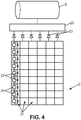
- FIG. 4 An example of a solar generator 2 is shown schematically on the figure 4 . It comprises a matrix of solar cells 20 comprising at least one junction, and preferably at least two-junctions - one then speaks of multi-junction cells - each junction of a solar cell being suitable for converting photons of a band of respective wavelengths in electric current by photovoltaic effect.
- the solar cells 20 of the solar generator can typically be triple junction cells, such as for example cells according to models 3G28 or 3G30 marketed by the company Azurspace, the spectral response of the latter being represented on the figure 5 , whose abscissa represents the wavelengths, and the left ordinate represents the rate of photoelectric conversion of the cell (also called External Quantum Efficiency EQE).
- triple junction cells such as for example cells according to models 3G28 or 3G30 marketed by the company Azurspace, the spectral response of the latter being represented on the figure 5 , whose abscissa represents the wavelengths, and the left ordinate represents the rate of photoelectric conversion of the cell (also called External Quantum Efficiency EQE).
- matrix of solar cells is meant that the solar cells are arranged in a regular arrangement, with a constant distance between two neighboring solar cells (which may include a first distance in a first direction and a second distance in a second direction orthogonal to the first one).
- solar cells are divided into rows all comprising the same number of cells.
- the solar cells 20 of the solar generator 2 are distributed by chains 21, each chain comprising a plurality of solar cells 20 connected in series with one another.
- chains 21 each chain comprising a plurality of solar cells 20 connected in series with one another.
- six chains of solar cells have been shown by way of example.
- the solar generator 2 can comprise one or more bypass diodes 22, also called bypass diodes, a bypass diode being connected in parallel with one or more solar cells 20 and making it possible to short-circuit the solar cell (s). to which it is connected if it is shaded.
- solar generator 2 may include a bypass diode 22 for each solar cell, as shown schematically in Figure. figure 4 , only one of the six solar cell chains being detailed there.
- the solar generator 2 can also include, for each chain 21, a chain blocking diode 23, making it possible to prevent the current from flowing in the opposite direction in a chain in the event of shading.
- the solar generator is connected to a power regulator 25 of the direct energy transfer type (also called DET in English) or of monitoring the maximum power point (also called MPPT of the acronym in English "Maximum Power Point. Tracking ”) according to the needs of the satellite.
- the current converted by the regulator 25 can then be used to power the satellite S or the drone to which the solar generator is mounted.
- the test device 1 of a solar generator comprises a lighting device 19 comprising a matrix 10 of light sources 11, where again the term matrix is interpreted as a set of several light sources distributed in a regular arrangement, for example example with a constant distance between two adjacent light sources (possibly comprising a first distance along a first direction and a second distance along a second direction orthogonal to the first).
- the light sources 11 of the matrix are distributed in rows all comprising the same number of light sources.
- the light sources are arranged on a flat support, thus forming a panel of a size and geometry that can be configured according to the solar generator to be tested.
- each light source 11 of the matrix 10 is adapted to emit light in at least one of the electrical conversion wavelength bands of the junctions of the solar cells.
- each light source 11 of the array 10 is adapted to emit light in each of the electrical conversion wavelength bands of the junctions of the solar cells.
- each light source 11 can comprise at least one light-emitting diode (called LED hereinafter) for each junction of the solar cell, each light-emitting diode being adapted to generate light in a band of wavelengths absorbed by a respective junction of the solar cell.
- LED light-emitting diode
- the nature of the light source can vary depending on the nature of the solar cells, and more precisely the emission ranges of the LEDs can vary depending on the junctions of the solar cells.
- each light source 11 can also include several LEDs for each junction of a solar cell, for example two or three LEDs making it possible to illuminate in the wavelength band of each junction.
- the light sources 11 of the array are adapted to emit light in a single band of electrical conversion wavelengths of the solar cells.
- the lighting device 19 can also comprise, in order to illuminate solar cells with multiple junctions, at least one secondary light source 18 adapted to emit light in the other wavelength band or bands of electrical conversion of the solar cells. More generally, this case could also apply if the light sources 11 are capable of illuminating in more than one band of wavelengths, at maximum N-1 bands of electrical conversion lengths of solar cells corresponding to N-1 junctions, N being the number of junctions of a cell.
- the test device 1 further comprises a power supply 14 of the matrix 10 of light sources and, where appropriate, of the secondary source (s) 18.
- This supply converts the mains voltage (220V single or three-phase for example) into voltage suitable for matrices.
- the choice of voltage is determined to minimize the supply current to the dies and can typically be selected between 10 and 40V.
- the lighting device is therefore adapted to be able to illuminate each solar cell of the solar generator in each band of wavelengths corresponding to a junction of the cell, and it is adapted to allow individually switchable lighting for each solar cell for at least one of the junctions, in order to be able to selectively switch each cell between a state where it does not deliver current (at least one junction is not illuminated) and a state where, in normal operation, it delivers current (all the junctions are illuminated).
- the switching of each light source makes it possible to switch from one state to another for each cell.
- the lighting device 19 further comprises one or more secondary light sources 18 for the others junctions, it suffices to illuminate the solar generator with the secondary source (s) 18 and to switch the light sources of the matrix 10 to activate the missing junction and thus switch from one state to another for each cell.
- the lighting device is suitable for lighting the solar cells with a surface light power received by the solar cell greater than or equal to at least 130W / m 2 , which corresponds to the cumulative power in all the bands of lengths of waves corresponding to all junctions
- solar cell of a measurable electric current thus making it possible to evaluate, by analyzing the response current, whether the illuminated solar cell is functional or not.
- This light power is also about a tenth of the light power received from the sun by the solar cells of a satellite solar generator in use in space.
- the matrix 10 of light sources preferably comprises at least as many light sources as the solar generator comprises solar cells, so that at least one light source corresponds to a given solar cell, and that the ignition of the source causes the illumination of the corresponding cell.
- the distance between two light sources is less than or equal to the distance between the centers of two solar cells of the solar generator.
- the matrix 10 of light sources may comprise light sources in number multiple of the number of solar cells of the generator.
- the solar generators conventionally used for satellites have a density of solar cells such that the distance between the centers of two adjacent solar cells is typically between 4 and 14 cm.
- the matrix of light sources of the test device can have a density of light sources greater than the density of solar cells, corresponding to a distance between two adjacent light sources of less than 5 cm, preferably less than 1 cm, for example. example of 5mm.
- the lighting device 19 also comprises one or more secondary light sources 18, that the requirements in terms of individual lighting of each solar cell only apply to the matrix 10 of light sources 11. since it is this matrix 10 which allows individual switching of the cells, and the secondary light source (s) can be coarser for more diffused lighting. Thus each secondary light source could cover several cells, or even the entire generator.
- each LED has integrated optics to reduce the angular opening of the emitted beam to 10 ° or less.
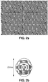
- FIG 2a An example of a light source suitable for cells with four junctions, comprising four LEDs whose emission bands are respectively centered on four different wavelengths, the four LEDs being mounted on a common card and each LED comprising an optic integrated to reduce the angular opening of the beam to 10 °.
- the beam generated by the example shown has a diameter of 23 mm and therefore makes it possible to significantly illuminate a single cell of the generator.
- FIG. 2b there is shown in figure 2b an example of a high density matrix comprising rows of LEDs adapted to four junctions of solar cells, the rows of LEDs being arranged in a compact manner.
- the pitch between two adjacent LEDs is 4 mm in the horizontal direction and in the direction defined by a row.
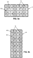
- the array 10 of light sources comprises a plurality of sub-arrays 15 which can be assembled together, each sub-array 15 may be individually powered and connected to the computer 13.
- each sub-matrix then comprises a microcontroller 120 making it possible to control all of the light sources of the sub-matrix.
- Each sub-matrix 15 comprises at least one, and preferably several light sources 11.
- a sub-matrix 15 comprises at least one row of light sources 11.
- the test device 1 further comprises a frame 16, shown schematically on the figure 1b , and allowing the assembly of the sub-matrices to form a matrix of desired geometry.
- the frame can for example comprise a set of locations 160, each location being suitable for receiving a sub-matrix, for example by screwing or bolting or snapping.
- a sub-matrix comprises 4 rows of 4 light sources 11.
- a sub-matrix has 2 rows of 9 light sources 11.
- the test device advantageously comprises an optic (not shown) making it possible to control, and advantageously reduce, the opening angle of the light beam emitted by each source 11.
- This optic can for example comprise one or more lens (s), and / or one or more diaphragm (s).
- the optics can also be integrated directly on the LEDs to allow the increase in the density of the LEDs.
- the value of the maximum opening angle not to be exceeded depends on other parameters including in particular the distance between the solar cells and the light sources. Typically, this distance is preferably greater than 5 cm, because below there is a risk of contact, and therefore of degradation, of the solar generator by the test device. This distance is preferably less than 15 to 20 cm, because beyond that there is a risk of dazzling operators working near the test device.
- the distance between solar cells and light sources can be 10cm
- the aperture angle control optics can be adapted to reduce the aperture angle of the light beam to an angle less than 15 °, for example equal to 10 °.
- the power received by the solar cells also depends on the density of the light sources, the power emitted by the light sources, the distance and opening angle of the light beam.
- each source being adapted to generate light in each band of wavelengths corresponding to a junction of a cell, and each source 11 being, in test, placed at a distance of between 5 and 15 cm from the solar generator and having an opening degree of less than 15 °
- the light source is advantageously configured to generate a power of 1 to 2 Watts per 10 cm 2 .
- the test device 1 advantageously comprises a device 18 for protecting the solar generator.
- This protection device 18 advantageously comprises a transparent screen 180 extending between the light sources 11 of the matrix and the solar cells, adapted to provide both mechanical protection, in the event of failure of the light sources (protection, confinement of the light source). pollution generated), and thermal.
- the transparent screen 180 is advantageously suitable for blocking infrared rays of wavelength greater than 1.8 ⁇ m in order to limit the heating of the solar generator.
- this transparent screen 180 can be mounted on the frame 16, at a distance from the latter making it possible to position the matrix 10 of light sources while maintaining a space between the light sources and the screen allowing the circulation of air.
- the protection device 18 can also include a fan 181 adapted to renew the air in the space between the light sources and the screen 180.
- the protection device 18 can also include a radiator 182 on the face. rear of the array of light sources, that is to say the face of the array oriented away from the solar generator, the radiator 182 being adapted to remove the heat produced by the sources, and thus contributing to thermal protection of the solar generator.
- each light source 11 of the matrix 10 can also be orientable, in order to be able to be adapted to several geometries of solar generator and to allow the most precise possible illumination of individual solar cells.
- a method of testing a solar generator using the test device described above comprises the positioning 100 of the array of light sources opposite the array of solar cells of the solar generator.
- the test device has been configured beforehand as a function of the solar generator to be tested, both by the number and arrangement of the light sources, and by the nature and the emission spectra of the light sources.
- the test device has been configured by selecting the number and the arrangement of the sub-matrices allowing to test the whole of the solar generator, and by them. assembling according to this configuration.
- the matrix 10 of light sources and preferably the frame 16 on which the matrix is mounted, are advantageously fixed to a mobile carriage (not shown), advantageously comprising means for adjusting the position and orientation of the matrix 10 of light sources mounted thereon. It is therefore possible to mount the matrix 10 of light sources on the trolley, then bring the trolley to the solar generator and make the adjustments to position the light sources opposite the solar cells.
- the array of light sources is positioned so that at least one light source is located opposite each solar cell, at a distance of less than 20 cm, and preferably less than 15 cm, but greater than 5 cm.
- the method comprises the illumination 200 of at least one solar cell of the solar generator on all of the wavelength bands corresponding to the junction (s) of the solar cell, by the ignition of at least one source. light 11 from the matrix, and where appropriate from the secondary source.
- this step will be described below. In the case where the lighting device comprises only the matrix 10 of light sources 11, this step is implemented by switching on one or more light sources to correspond to the cell or cells for which it is desired to activate the generation of current.
- this step comprises the ignition of the secondary source to illuminate at least the cell or cells for which it is desired to activate the generation of current, and the ignition of a or several light sources 11 of the matrix corresponding to the cell (s), the ignition of the sources 11 to allow switching of the cells.
- the method then comprises measuring 300 of a response current of the illuminated solar cell (s).
- the measured response current is preferably the supply current of the satellite or the drone, since it is possible to access this current without accessing the internal electrical connections of the solar generator (for example the connections between two cells or two strings) , and therefore this minimizes the risks of degradation by handling the solar generator.
- the measured response current is then analyzed during a step 400, by an operator or by an algorithm implemented by a processor, to deduce therefrom a healthy or defective state of the solar generator.
- the analysis carried out depends on the type of illumination used and on the nature of the test which is carried out. It can for example, but without limitation, comprise the comparison of a current value measured with a threshold determined as a function of the number of illuminated cells, and the detection of a malfunction if the measured current is lower than said threshold.
- Satellites are sometimes equipped with an automatic start feature if the supply current generated by the solar generators exceeds a predetermined threshold (corresponding to at least partial sunlight of the solar generators).
- a predetermined threshold corresponding to at least partial sunlight of the solar generators.
- this functionality can be tested, as well as the correct connection of the solar generator to the satellite, by simultaneously turning on all of the light sources to illuminate the entire solar generator.
- the method comprises the selective illumination 200 of a chain of cells, by simultaneous illumination of all the cells of the chain, and the analysis of the output current makes it possible to verify the correct connection of the chain to the satellite or to the satellite. drone, the integrity of the wiring, the correct allocation of the channel to a channel of the regulator 25 which must correspond to it, the correct operation of the regulator, as well as the correct operation of the corresponding chain blocking diode.
- the method can comprise an illumination 200 simulating a shading of a part of the solar generator, in order to verify the correct operation of the MPPT regulator. It is then verified that the power of the satellite supply current is the maximum power taking into account the shaded cells.
- the method can also comprise the successive illumination 200 of groups of solar cells in a chain, the groups comprising a constant number of solar cells and the successively illuminated groups being offset from one another by a single solar cell, this illumination forming a progressive scan of the channel.
- the evolution of the current during this scan makes it possible to detect a malfunction of a cell or of the corresponding bypass diode, or even a defective electrical contact between the cells of the chain. For example, if the current is constant during the scanning but undergoes a localized decrease, then one can deduce from this a malfunction of the cell or of the bypass diode added last at the level of the group corresponding to the decrease in current.
- this test comprises the first illumination of the cell arranged upstream of that where the malfunction is located, then of this one. , and current analysis for each illuminated cell. If when lighting the cell placed upstream, no current is measurable, and when lighting the next cell a current is detected, then it can be deduced that the bypass diode is defective and is in open circuit. On the other hand, if when we light the cell placed upstream, we detect a current, and this current decreases when we light the next cell, then we can deduce that the cell is defective or that the bypass diode is short-circuited.
- the test device presented above makes it possible to carry out a set of tests on a solar generator without handling or contacting the solar generator, which reduces the risk of damage.
- the individual solicitation of solar cells makes it possible to test the operation of cells or identified chains, which makes it possible to accurately detect the location of a fault.
Landscapes
- Physics & Mathematics (AREA)
- General Physics & Mathematics (AREA)
- Engineering & Computer Science (AREA)
- Microelectronics & Electronic Packaging (AREA)
- Condensed Matter Physics & Semiconductors (AREA)
- Electromagnetism (AREA)
- Computer Hardware Design (AREA)
- Power Engineering (AREA)
- Sustainable Development (AREA)
- Life Sciences & Earth Sciences (AREA)
- General Engineering & Computer Science (AREA)
- Photovoltaic Devices (AREA)
- Testing Of Individual Semiconductor Devices (AREA)
- Testing Of Optical Devices Or Fibers (AREA)
Applications Claiming Priority (2)
| Application Number | Priority Date | Filing Date | Title |
|---|---|---|---|
| FR1855824A FR3083405B1 (fr) | 2018-06-28 | 2018-06-28 | Dispositif de test d'un generateur solaire de satellite |
| PCT/FR2019/051420 WO2020002791A1 (fr) | 2018-06-28 | 2019-06-12 | Dispositif de test d'un generateur solaire de satellite |
Publications (2)
| Publication Number | Publication Date |
|---|---|
| EP3649732A1 EP3649732A1 (fr) | 2020-05-13 |
| EP3649732B1 true EP3649732B1 (fr) | 2020-10-28 |
Family
ID=63896306
Family Applications (1)
| Application Number | Title | Priority Date | Filing Date |
|---|---|---|---|
| EP19737855.7A Active EP3649732B1 (fr) | 2018-06-28 | 2019-06-12 | Dispositif de test d'un generateur solaire de satellite |
Country Status (6)
| Country | Link |
|---|---|
| US (1) | US11183970B2 (ja) |
| EP (1) | EP3649732B1 (ja) |
| JP (1) | JP7090752B2 (ja) |
| CN (1) | CN112425068B (ja) |
| FR (1) | FR3083405B1 (ja) |
| WO (1) | WO2020002791A1 (ja) |
Families Citing this family (2)
| Publication number | Priority date | Publication date | Assignee | Title |
|---|---|---|---|---|
| DE102020210999A1 (de) * | 2020-09-01 | 2022-03-03 | Forschungszentrum Jülich GmbH | Verfahren und System zur Bewertung von Solarzellen |
| CN114537638A (zh) * | 2021-12-21 | 2022-05-27 | 中国航天空气动力技术研究院 | 一种太阳能飞行器口盖、飞行器及其使用方法 |
Family Cites Families (17)
| Publication number | Priority date | Publication date | Assignee | Title |
|---|---|---|---|---|
| JP3270303B2 (ja) * | 1995-07-26 | 2002-04-02 | キヤノン株式会社 | 電池電源装置特性測定装置および測定方法 |
| JP5013637B2 (ja) * | 2000-07-04 | 2012-08-29 | キヤノン株式会社 | 光電変換特性の測定方法およびその装置 |
| JP2002111030A (ja) | 2000-07-05 | 2002-04-12 | Canon Inc | 光電変換デバイスの、光電変換特性の測定または予測方法、および、スペクトル依存性の定量化方法、並びに、それらの装置 |
| CN1260576C (zh) * | 2000-10-17 | 2006-06-21 | 施密德技术系统有限公司 | 用于检测太阳能电池的设备 |
| JP2007078404A (ja) | 2005-09-12 | 2007-03-29 | Mitsubishi Electric Corp | 太陽電池パネル検査装置 |
| JP2011049474A (ja) | 2009-08-28 | 2011-03-10 | Sharp Corp | 太陽電池評価装置 |
| CN101696942B (zh) * | 2009-10-16 | 2011-03-30 | 厦门大学 | 多结太阳能电池及各子电池交流电致发光测试方法和装置 |
| TWI440794B (zh) | 2010-09-27 | 2014-06-11 | Ind Tech Res Inst | 太陽光模擬器 |
| US9423448B1 (en) * | 2011-03-06 | 2016-08-23 | Sunpower Corporation | Testing of module integrated electronics using power reversal |
| US10170652B2 (en) | 2011-03-22 | 2019-01-01 | The Boeing Company | Metamorphic solar cell having improved current generation |
| ITUD20110115A1 (it) | 2011-07-19 | 2013-01-20 | Applied Materials Italia Srl | Dispositivo per la simulazione della radiazione solare e procedimento di test che utilizza tale dispositivo |
| JP2015043395A (ja) | 2013-08-26 | 2015-03-05 | 国立大学法人 奈良先端科学技術大学院大学 | 太陽電池装置及びその利用 |
| US20170084771A1 (en) | 2015-09-21 | 2017-03-23 | The Boeing Company | Antimonide-based high bandgap tunnel junction for semiconductor devices |
| JP3203781U (ja) | 2016-02-05 | 2016-04-14 | 日清紡メカトロニクス株式会社 | ソーラシミュレータ |
| JP6520771B2 (ja) | 2016-03-11 | 2019-05-29 | オムロン株式会社 | 太陽電池の故障検出装置および太陽光発電システム |
| CN106230379B (zh) * | 2016-07-27 | 2018-06-26 | 天津三安光电有限公司 | 一种多结太阳电池芯片的检测装置及检测方法 |
| CN106877818B (zh) * | 2017-03-14 | 2019-03-01 | 华东师范大学 | 一种多结太阳能电池子结之间发光耦合效率的检测装置及方法 |
-
2018
- 2018-06-28 FR FR1855824A patent/FR3083405B1/fr not_active Expired - Fee Related
-
2019
- 2019-06-12 WO PCT/FR2019/051420 patent/WO2020002791A1/fr unknown
- 2019-06-12 CN CN201980047664.4A patent/CN112425068B/zh active Active
- 2019-06-12 US US17/256,379 patent/US11183970B2/en active Active
- 2019-06-12 JP JP2020571780A patent/JP7090752B2/ja active Active
- 2019-06-12 EP EP19737855.7A patent/EP3649732B1/fr active Active
Non-Patent Citations (1)
| Title |
|---|
| None * |
Also Published As
| Publication number | Publication date |
|---|---|
| US11183970B2 (en) | 2021-11-23 |
| FR3083405B1 (fr) | 2020-07-31 |
| CN112425068A (zh) | 2021-02-26 |
| CN112425068B (zh) | 2021-09-14 |
| EP3649732A1 (fr) | 2020-05-13 |
| JP7090752B2 (ja) | 2022-06-24 |
| FR3083405A1 (fr) | 2020-01-03 |
| US20210249993A1 (en) | 2021-08-12 |
| JP2021524225A (ja) | 2021-09-09 |
| WO2020002791A1 (fr) | 2020-01-02 |
Similar Documents
| Publication | Publication Date | Title |
|---|---|---|
| EP3649732B1 (fr) | Dispositif de test d'un generateur solaire de satellite | |
| EP2380069B1 (fr) | Système de gestion électronique de cellules photovoltaiques | |
| EP1679469A1 (fr) | Dispositif de signalisation lumineux | |
| FR2984011A1 (fr) | Appareil pour le cablage industriel et les tests finaux de modules concentrateurs photovoltaiques | |
| WO2011070548A1 (fr) | Systeme de gestion electronique de cellules photovoltaiques fonction de la meteorologie | |
| WO2014044603A1 (fr) | Procede de caracterisation d'un element photovoltaique, dispositif de caracterisation de l'element photovoltaique, programme et support d'enregistrement associes | |
| Dubey et al. | On-site electroluminescence study of field-aged PV modules | |
| EP3069156B1 (fr) | Dispositif et procede de test d'un module photovoltaique a concentration | |
| FR3070560B1 (fr) | Procede d'analyse quantitative d'une installation comprenant un module electroluminescent | |
| EP3987655B1 (fr) | Procede de caracterisation electrique d'une cellule photovoltaique decoupee | |
| Chicca et al. | Nondestructive techniques to determine degradation modes: Experimentation with 18 years old photovoltaic modules | |
| FR3139959A1 (fr) | Procédé de test d’au moins une diode de dérivation sur une installation comportant au moins un module photovoltaïque en fonctionnement | |
| KR20170118384A (ko) | 컨버터 일체형 태양전지모듈 정션박스 | |
| FR2982373A1 (fr) | Dispositif d'aide a la maintenance d'une installation photovoltaique. | |
| US11876484B2 (en) | Protecting solar panels from damage due to overheating | |
| FR3118363A1 (fr) | Procédé et système d'estimation de la puissance électrique fournie par un module photovoltaïque | |
| FR2944143A1 (fr) | Detection de salissure | |
| Malefafana et al. | Electroluminescence imaging of photovoltaic modules | |
| EP0495698A1 (fr) | Procédé et dispositif de test de diodes à jonction apparente assemblées en parallèle | |
| FR3108445A1 (fr) | Module solaire amélioré | |
| WO2022128446A1 (fr) | Dispositif photovoltaïque bifacial de reference | |
| AU2022295557A1 (en) | Outdoor photoluminescence imaging of photovoltaic arrays via optical string modulation | |
| FR3129627A1 (fr) | Installation et procédé de désassemblage d'un module photovoltaïque | |
| FR3124578A1 (fr) | Procédé de fonctionnement d'un dispositif d'éclairage automobile et dispositif d'éclairage automobile | |
| FR2963987A1 (fr) | Installation photovoltaique et procede permettant de delivrer une puissance electrique egale a une valeur predeterminee. |
Legal Events
| Date | Code | Title | Description |
|---|---|---|---|
| STAA | Information on the status of an ep patent application or granted ep patent |
Free format text: STATUS: UNKNOWN |
|
| STAA | Information on the status of an ep patent application or granted ep patent |
Free format text: STATUS: THE INTERNATIONAL PUBLICATION HAS BEEN MADE |
|
| PUAI | Public reference made under article 153(3) epc to a published international application that has entered the european phase |
Free format text: ORIGINAL CODE: 0009012 |
|
| STAA | Information on the status of an ep patent application or granted ep patent |
Free format text: STATUS: REQUEST FOR EXAMINATION WAS MADE |
|
| 17P | Request for examination filed |
Effective date: 20200203 |
|
| AK | Designated contracting states |
Kind code of ref document: A1 Designated state(s): AL AT BE BG CH CY CZ DE DK EE ES FI FR GB GR HR HU IE IS IT LI LT LU LV MC MK MT NL NO PL PT RO RS SE SI SK SM TR |
|
| AX | Request for extension of the european patent |
Extension state: BA ME |
|
| GRAP | Despatch of communication of intention to grant a patent |
Free format text: ORIGINAL CODE: EPIDOSNIGR1 |
|
| STAA | Information on the status of an ep patent application or granted ep patent |
Free format text: STATUS: GRANT OF PATENT IS INTENDED |
|
| DAV | Request for validation of the european patent (deleted) | ||
| DAX | Request for extension of the european patent (deleted) | ||
| INTG | Intention to grant announced |
Effective date: 20200519 |
|
| GRAS | Grant fee paid |
Free format text: ORIGINAL CODE: EPIDOSNIGR3 |
|
| GRAA | (expected) grant |
Free format text: ORIGINAL CODE: 0009210 |
|
| STAA | Information on the status of an ep patent application or granted ep patent |
Free format text: STATUS: THE PATENT HAS BEEN GRANTED |
|
| AK | Designated contracting states |
Kind code of ref document: B1 Designated state(s): AL AT BE BG CH CY CZ DE DK EE ES FI FR GB GR HR HU IE IS IT LI LT LU LV MC MK MT NL NO PL PT RO RS SE SI SK SM TR |
|
| REG | Reference to a national code |
Ref country code: GB Ref legal event code: FG4D Free format text: NOT ENGLISH |
|
| REG | Reference to a national code |
Ref country code: CH Ref legal event code: EP |
|
| REG | Reference to a national code |
Ref country code: AT Ref legal event code: REF Ref document number: 1329255 Country of ref document: AT Kind code of ref document: T Effective date: 20201115 |
|
| REG | Reference to a national code |
Ref country code: DE Ref legal event code: R096 Ref document number: 602019001110 Country of ref document: DE |
|
| REG | Reference to a national code |
Ref country code: IE Ref legal event code: FG4D Free format text: LANGUAGE OF EP DOCUMENT: FRENCH |
|
| REG | Reference to a national code |
Ref country code: AT Ref legal event code: MK05 Ref document number: 1329255 Country of ref document: AT Kind code of ref document: T Effective date: 20201028 |
|
| REG | Reference to a national code |
Ref country code: NL Ref legal event code: MP Effective date: 20201028 |
|
| PG25 | Lapsed in a contracting state [announced via postgrant information from national office to epo] |
Ref country code: FI Free format text: LAPSE BECAUSE OF FAILURE TO SUBMIT A TRANSLATION OF THE DESCRIPTION OR TO PAY THE FEE WITHIN THE PRESCRIBED TIME-LIMIT Effective date: 20201028 Ref country code: PT Free format text: LAPSE BECAUSE OF FAILURE TO SUBMIT A TRANSLATION OF THE DESCRIPTION OR TO PAY THE FEE WITHIN THE PRESCRIBED TIME-LIMIT Effective date: 20210301 Ref country code: RS Free format text: LAPSE BECAUSE OF FAILURE TO SUBMIT A TRANSLATION OF THE DESCRIPTION OR TO PAY THE FEE WITHIN THE PRESCRIBED TIME-LIMIT Effective date: 20201028 Ref country code: GR Free format text: LAPSE BECAUSE OF FAILURE TO SUBMIT A TRANSLATION OF THE DESCRIPTION OR TO PAY THE FEE WITHIN THE PRESCRIBED TIME-LIMIT Effective date: 20210129 Ref country code: NO Free format text: LAPSE BECAUSE OF FAILURE TO SUBMIT A TRANSLATION OF THE DESCRIPTION OR TO PAY THE FEE WITHIN THE PRESCRIBED TIME-LIMIT Effective date: 20210128 |
|
| REG | Reference to a national code |
Ref country code: LT Ref legal event code: MG4D |
|
| PG25 | Lapsed in a contracting state [announced via postgrant information from national office to epo] |
Ref country code: SE Free format text: LAPSE BECAUSE OF FAILURE TO SUBMIT A TRANSLATION OF THE DESCRIPTION OR TO PAY THE FEE WITHIN THE PRESCRIBED TIME-LIMIT Effective date: 20201028 Ref country code: PL Free format text: LAPSE BECAUSE OF FAILURE TO SUBMIT A TRANSLATION OF THE DESCRIPTION OR TO PAY THE FEE WITHIN THE PRESCRIBED TIME-LIMIT Effective date: 20201028 Ref country code: LV Free format text: LAPSE BECAUSE OF FAILURE TO SUBMIT A TRANSLATION OF THE DESCRIPTION OR TO PAY THE FEE WITHIN THE PRESCRIBED TIME-LIMIT Effective date: 20201028 Ref country code: IS Free format text: LAPSE BECAUSE OF FAILURE TO SUBMIT A TRANSLATION OF THE DESCRIPTION OR TO PAY THE FEE WITHIN THE PRESCRIBED TIME-LIMIT Effective date: 20210228 Ref country code: BG Free format text: LAPSE BECAUSE OF FAILURE TO SUBMIT A TRANSLATION OF THE DESCRIPTION OR TO PAY THE FEE WITHIN THE PRESCRIBED TIME-LIMIT Effective date: 20210128 Ref country code: AT Free format text: LAPSE BECAUSE OF FAILURE TO SUBMIT A TRANSLATION OF THE DESCRIPTION OR TO PAY THE FEE WITHIN THE PRESCRIBED TIME-LIMIT Effective date: 20201028 Ref country code: ES Free format text: LAPSE BECAUSE OF FAILURE TO SUBMIT A TRANSLATION OF THE DESCRIPTION OR TO PAY THE FEE WITHIN THE PRESCRIBED TIME-LIMIT Effective date: 20201028 |
|
| PG25 | Lapsed in a contracting state [announced via postgrant information from national office to epo] |
Ref country code: HR Free format text: LAPSE BECAUSE OF FAILURE TO SUBMIT A TRANSLATION OF THE DESCRIPTION OR TO PAY THE FEE WITHIN THE PRESCRIBED TIME-LIMIT Effective date: 20201028 Ref country code: NL Free format text: LAPSE BECAUSE OF FAILURE TO SUBMIT A TRANSLATION OF THE DESCRIPTION OR TO PAY THE FEE WITHIN THE PRESCRIBED TIME-LIMIT Effective date: 20201028 |
|
| REG | Reference to a national code |
Ref country code: DE Ref legal event code: R097 Ref document number: 602019001110 Country of ref document: DE |
|
| PG25 | Lapsed in a contracting state [announced via postgrant information from national office to epo] |
Ref country code: LT Free format text: LAPSE BECAUSE OF FAILURE TO SUBMIT A TRANSLATION OF THE DESCRIPTION OR TO PAY THE FEE WITHIN THE PRESCRIBED TIME-LIMIT Effective date: 20201028 Ref country code: RO Free format text: LAPSE BECAUSE OF FAILURE TO SUBMIT A TRANSLATION OF THE DESCRIPTION OR TO PAY THE FEE WITHIN THE PRESCRIBED TIME-LIMIT Effective date: 20201028 Ref country code: CZ Free format text: LAPSE BECAUSE OF FAILURE TO SUBMIT A TRANSLATION OF THE DESCRIPTION OR TO PAY THE FEE WITHIN THE PRESCRIBED TIME-LIMIT Effective date: 20201028 Ref country code: EE Free format text: LAPSE BECAUSE OF FAILURE TO SUBMIT A TRANSLATION OF THE DESCRIPTION OR TO PAY THE FEE WITHIN THE PRESCRIBED TIME-LIMIT Effective date: 20201028 Ref country code: SM Free format text: LAPSE BECAUSE OF FAILURE TO SUBMIT A TRANSLATION OF THE DESCRIPTION OR TO PAY THE FEE WITHIN THE PRESCRIBED TIME-LIMIT Effective date: 20201028 Ref country code: SK Free format text: LAPSE BECAUSE OF FAILURE TO SUBMIT A TRANSLATION OF THE DESCRIPTION OR TO PAY THE FEE WITHIN THE PRESCRIBED TIME-LIMIT Effective date: 20201028 |
|
| PG25 | Lapsed in a contracting state [announced via postgrant information from national office to epo] |
Ref country code: DK Free format text: LAPSE BECAUSE OF FAILURE TO SUBMIT A TRANSLATION OF THE DESCRIPTION OR TO PAY THE FEE WITHIN THE PRESCRIBED TIME-LIMIT Effective date: 20201028 |
|
| PLBE | No opposition filed within time limit |
Free format text: ORIGINAL CODE: 0009261 |
|
| STAA | Information on the status of an ep patent application or granted ep patent |
Free format text: STATUS: NO OPPOSITION FILED WITHIN TIME LIMIT |
|
| 26N | No opposition filed |
Effective date: 20210729 |
|
| PG25 | Lapsed in a contracting state [announced via postgrant information from national office to epo] |
Ref country code: AL Free format text: LAPSE BECAUSE OF FAILURE TO SUBMIT A TRANSLATION OF THE DESCRIPTION OR TO PAY THE FEE WITHIN THE PRESCRIBED TIME-LIMIT Effective date: 20201028 |
|
| PG25 | Lapsed in a contracting state [announced via postgrant information from national office to epo] |
Ref country code: SI Free format text: LAPSE BECAUSE OF FAILURE TO SUBMIT A TRANSLATION OF THE DESCRIPTION OR TO PAY THE FEE WITHIN THE PRESCRIBED TIME-LIMIT Effective date: 20201028 |
|
| PG25 | Lapsed in a contracting state [announced via postgrant information from national office to epo] |
Ref country code: MC Free format text: LAPSE BECAUSE OF FAILURE TO SUBMIT A TRANSLATION OF THE DESCRIPTION OR TO PAY THE FEE WITHIN THE PRESCRIBED TIME-LIMIT Effective date: 20201028 |
|
| PG25 | Lapsed in a contracting state [announced via postgrant information from national office to epo] |
Ref country code: LU Free format text: LAPSE BECAUSE OF NON-PAYMENT OF DUE FEES Effective date: 20210612 |
|
| PG25 | Lapsed in a contracting state [announced via postgrant information from national office to epo] |
Ref country code: IE Free format text: LAPSE BECAUSE OF NON-PAYMENT OF DUE FEES Effective date: 20210612 |
|
| PG25 | Lapsed in a contracting state [announced via postgrant information from national office to epo] |
Ref country code: IS Free format text: LAPSE BECAUSE OF FAILURE TO SUBMIT A TRANSLATION OF THE DESCRIPTION OR TO PAY THE FEE WITHIN THE PRESCRIBED TIME-LIMIT Effective date: 20210228 |
|
| REG | Reference to a national code |
Ref country code: CH Ref legal event code: PL |
|
| PG25 | Lapsed in a contracting state [announced via postgrant information from national office to epo] |
Ref country code: LI Free format text: LAPSE BECAUSE OF NON-PAYMENT OF DUE FEES Effective date: 20220630 Ref country code: CH Free format text: LAPSE BECAUSE OF NON-PAYMENT OF DUE FEES Effective date: 20220630 |
|
| PG25 | Lapsed in a contracting state [announced via postgrant information from national office to epo] |
Ref country code: CY Free format text: LAPSE BECAUSE OF FAILURE TO SUBMIT A TRANSLATION OF THE DESCRIPTION OR TO PAY THE FEE WITHIN THE PRESCRIBED TIME-LIMIT Effective date: 20201028 |
|
| PG25 | Lapsed in a contracting state [announced via postgrant information from national office to epo] |
Ref country code: HU Free format text: LAPSE BECAUSE OF FAILURE TO SUBMIT A TRANSLATION OF THE DESCRIPTION OR TO PAY THE FEE WITHIN THE PRESCRIBED TIME-LIMIT; INVALID AB INITIO Effective date: 20190612 |
|
| PGFP | Annual fee paid to national office [announced via postgrant information from national office to epo] |
Ref country code: FR Payment date: 20230628 Year of fee payment: 5 Ref country code: DE Payment date: 20230620 Year of fee payment: 5 |
|
| PGFP | Annual fee paid to national office [announced via postgrant information from national office to epo] |
Ref country code: BE Payment date: 20230619 Year of fee payment: 5 |
|
| PGFP | Annual fee paid to national office [announced via postgrant information from national office to epo] |
Ref country code: IT Payment date: 20230623 Year of fee payment: 5 Ref country code: GB Payment date: 20230622 Year of fee payment: 5 |