EP3648192A1 - Method for manufacturing cylindrical battery case having improved surface roughness - Google Patents
Method for manufacturing cylindrical battery case having improved surface roughness Download PDFInfo
- Publication number
- EP3648192A1 EP3648192A1 EP18870614.7A EP18870614A EP3648192A1 EP 3648192 A1 EP3648192 A1 EP 3648192A1 EP 18870614 A EP18870614 A EP 18870614A EP 3648192 A1 EP3648192 A1 EP 3648192A1
- Authority
- EP
- European Patent Office
- Prior art keywords
- battery case
- cylindrical
- surface roughness
- cylindrical battery
- ironing process
- Prior art date
- Legal status (The legal status is an assumption and is not a legal conclusion. Google has not performed a legal analysis and makes no representation as to the accuracy of the status listed.)
- Granted
Links
Images

Classifications
-
- H—ELECTRICITY
- H01—ELECTRIC ELEMENTS
- H01M—PROCESSES OR MEANS, e.g. BATTERIES, FOR THE DIRECT CONVERSION OF CHEMICAL ENERGY INTO ELECTRICAL ENERGY
- H01M50/00—Constructional details or processes of manufacture of the non-active parts of electrochemical cells other than fuel cells, e.g. hybrid cells
- H01M50/10—Primary casings; Jackets or wrappings
- H01M50/102—Primary casings; Jackets or wrappings characterised by their shape or physical structure
- H01M50/107—Primary casings; Jackets or wrappings characterised by their shape or physical structure having curved cross-section, e.g. round or elliptic
-
- C—CHEMISTRY; METALLURGY
- C21—METALLURGY OF IRON
- C21D—MODIFYING THE PHYSICAL STRUCTURE OF FERROUS METALS; GENERAL DEVICES FOR HEAT TREATMENT OF FERROUS OR NON-FERROUS METALS OR ALLOYS; MAKING METAL MALLEABLE, e.g. BY DECARBURISATION OR TEMPERING
- C21D9/00—Heat treatment, e.g. annealing, hardening, quenching or tempering, adapted for particular articles; Furnaces therefor
- C21D9/46—Heat treatment, e.g. annealing, hardening, quenching or tempering, adapted for particular articles; Furnaces therefor for sheet metals
- C21D9/48—Heat treatment, e.g. annealing, hardening, quenching or tempering, adapted for particular articles; Furnaces therefor for sheet metals deep-drawing sheets
-
- B—PERFORMING OPERATIONS; TRANSPORTING
- B21—MECHANICAL METAL-WORKING WITHOUT ESSENTIALLY REMOVING MATERIAL; PUNCHING METAL
- B21D—WORKING OR PROCESSING OF SHEET METAL OR METAL TUBES, RODS OR PROFILES WITHOUT ESSENTIALLY REMOVING MATERIAL; PUNCHING METAL
- B21D22/00—Shaping without cutting, by stamping, spinning, or deep-drawing
- B21D22/20—Deep-drawing
- B21D22/201—Work-pieces; preparation of the work-pieces, e.g. lubricating, coating
-
- B—PERFORMING OPERATIONS; TRANSPORTING
- B21—MECHANICAL METAL-WORKING WITHOUT ESSENTIALLY REMOVING MATERIAL; PUNCHING METAL
- B21D—WORKING OR PROCESSING OF SHEET METAL OR METAL TUBES, RODS OR PROFILES WITHOUT ESSENTIALLY REMOVING MATERIAL; PUNCHING METAL
- B21D22/00—Shaping without cutting, by stamping, spinning, or deep-drawing
- B21D22/20—Deep-drawing
- B21D22/28—Deep-drawing of cylindrical articles using consecutive dies
-
- B—PERFORMING OPERATIONS; TRANSPORTING
- B21—MECHANICAL METAL-WORKING WITHOUT ESSENTIALLY REMOVING MATERIAL; PUNCHING METAL
- B21D—WORKING OR PROCESSING OF SHEET METAL OR METAL TUBES, RODS OR PROFILES WITHOUT ESSENTIALLY REMOVING MATERIAL; PUNCHING METAL
- B21D22/00—Shaping without cutting, by stamping, spinning, or deep-drawing
- B21D22/20—Deep-drawing
- B21D22/30—Deep-drawing to finish articles formed by deep-drawing
-
- B—PERFORMING OPERATIONS; TRANSPORTING
- B21—MECHANICAL METAL-WORKING WITHOUT ESSENTIALLY REMOVING MATERIAL; PUNCHING METAL
- B21D—WORKING OR PROCESSING OF SHEET METAL OR METAL TUBES, RODS OR PROFILES WITHOUT ESSENTIALLY REMOVING MATERIAL; PUNCHING METAL
- B21D51/00—Making hollow objects
- B21D51/16—Making hollow objects characterised by the use of the objects
-
- C—CHEMISTRY; METALLURGY
- C23—COATING METALLIC MATERIAL; COATING MATERIAL WITH METALLIC MATERIAL; CHEMICAL SURFACE TREATMENT; DIFFUSION TREATMENT OF METALLIC MATERIAL; COATING BY VACUUM EVAPORATION, BY SPUTTERING, BY ION IMPLANTATION OR BY CHEMICAL VAPOUR DEPOSITION, IN GENERAL; INHIBITING CORROSION OF METALLIC MATERIAL OR INCRUSTATION IN GENERAL
- C23C—COATING METALLIC MATERIAL; COATING MATERIAL WITH METALLIC MATERIAL; SURFACE TREATMENT OF METALLIC MATERIAL BY DIFFUSION INTO THE SURFACE, BY CHEMICAL CONVERSION OR SUBSTITUTION; COATING BY VACUUM EVAPORATION, BY SPUTTERING, BY ION IMPLANTATION OR BY CHEMICAL VAPOUR DEPOSITION, IN GENERAL
- C23C30/00—Coating with metallic material characterised only by the composition of the metallic material, i.e. not characterised by the coating process
- C23C30/005—Coating with metallic material characterised only by the composition of the metallic material, i.e. not characterised by the coating process on hard metal substrates
-
- H—ELECTRICITY
- H01—ELECTRIC ELEMENTS
- H01M—PROCESSES OR MEANS, e.g. BATTERIES, FOR THE DIRECT CONVERSION OF CHEMICAL ENERGY INTO ELECTRICAL ENERGY
- H01M10/00—Secondary cells; Manufacture thereof
- H01M10/04—Construction or manufacture in general
- H01M10/0422—Cells or battery with cylindrical casing
-
- H—ELECTRICITY
- H01—ELECTRIC ELEMENTS
- H01M—PROCESSES OR MEANS, e.g. BATTERIES, FOR THE DIRECT CONVERSION OF CHEMICAL ENERGY INTO ELECTRICAL ENERGY
- H01M50/00—Constructional details or processes of manufacture of the non-active parts of electrochemical cells other than fuel cells, e.g. hybrid cells
- H01M50/10—Primary casings; Jackets or wrappings
- H01M50/116—Primary casings; Jackets or wrappings characterised by the material
- H01M50/117—Inorganic material
- H01M50/119—Metals
-
- H—ELECTRICITY
- H01—ELECTRIC ELEMENTS
- H01M—PROCESSES OR MEANS, e.g. BATTERIES, FOR THE DIRECT CONVERSION OF CHEMICAL ENERGY INTO ELECTRICAL ENERGY
- H01M50/00—Constructional details or processes of manufacture of the non-active parts of electrochemical cells other than fuel cells, e.g. hybrid cells
- H01M50/10—Primary casings; Jackets or wrappings
- H01M50/116—Primary casings; Jackets or wrappings characterised by the material
- H01M50/124—Primary casings; Jackets or wrappings characterised by the material having a layered structure
-
- H—ELECTRICITY
- H01—ELECTRIC ELEMENTS
- H01M—PROCESSES OR MEANS, e.g. BATTERIES, FOR THE DIRECT CONVERSION OF CHEMICAL ENERGY INTO ELECTRICAL ENERGY
- H01M50/00—Constructional details or processes of manufacture of the non-active parts of electrochemical cells other than fuel cells, e.g. hybrid cells
- H01M50/10—Primary casings; Jackets or wrappings
- H01M50/131—Primary casings; Jackets or wrappings characterised by physical properties, e.g. gas permeability, size or heat resistance
-
- H—ELECTRICITY
- H01—ELECTRIC ELEMENTS
- H01M—PROCESSES OR MEANS, e.g. BATTERIES, FOR THE DIRECT CONVERSION OF CHEMICAL ENERGY INTO ELECTRICAL ENERGY
- H01M50/00—Constructional details or processes of manufacture of the non-active parts of electrochemical cells other than fuel cells, e.g. hybrid cells
- H01M50/10—Primary casings; Jackets or wrappings
- H01M50/131—Primary casings; Jackets or wrappings characterised by physical properties, e.g. gas permeability, size or heat resistance
- H01M50/133—Thickness
-
- H—ELECTRICITY
- H01—ELECTRIC ELEMENTS
- H01M—PROCESSES OR MEANS, e.g. BATTERIES, FOR THE DIRECT CONVERSION OF CHEMICAL ENERGY INTO ELECTRICAL ENERGY
- H01M50/00—Constructional details or processes of manufacture of the non-active parts of electrochemical cells other than fuel cells, e.g. hybrid cells
- H01M50/10—Primary casings; Jackets or wrappings
- H01M50/14—Primary casings; Jackets or wrappings for protecting against damage caused by external factors
- H01M50/145—Primary casings; Jackets or wrappings for protecting against damage caused by external factors for protecting against corrosion
-
- B—PERFORMING OPERATIONS; TRANSPORTING
- B21—MECHANICAL METAL-WORKING WITHOUT ESSENTIALLY REMOVING MATERIAL; PUNCHING METAL
- B21D—WORKING OR PROCESSING OF SHEET METAL OR METAL TUBES, RODS OR PROFILES WITHOUT ESSENTIALLY REMOVING MATERIAL; PUNCHING METAL
- B21D35/00—Combined processes according to or processes combined with methods covered by groups B21D1/00 - B21D31/00
- B21D35/002—Processes combined with methods covered by groups B21D1/00 - B21D31/00
-
- H—ELECTRICITY
- H01—ELECTRIC ELEMENTS
- H01M—PROCESSES OR MEANS, e.g. BATTERIES, FOR THE DIRECT CONVERSION OF CHEMICAL ENERGY INTO ELECTRICAL ENERGY
- H01M2220/00—Batteries for particular applications
- H01M2220/10—Batteries in stationary systems, e.g. emergency power source in plant
-
- H—ELECTRICITY
- H01—ELECTRIC ELEMENTS
- H01M—PROCESSES OR MEANS, e.g. BATTERIES, FOR THE DIRECT CONVERSION OF CHEMICAL ENERGY INTO ELECTRICAL ENERGY
- H01M2220/00—Batteries for particular applications
- H01M2220/20—Batteries in motive systems, e.g. vehicle, ship, plane
-
- Y—GENERAL TAGGING OF NEW TECHNOLOGICAL DEVELOPMENTS; GENERAL TAGGING OF CROSS-SECTIONAL TECHNOLOGIES SPANNING OVER SEVERAL SECTIONS OF THE IPC; TECHNICAL SUBJECTS COVERED BY FORMER USPC CROSS-REFERENCE ART COLLECTIONS [XRACs] AND DIGESTS
- Y02—TECHNOLOGIES OR APPLICATIONS FOR MITIGATION OR ADAPTATION AGAINST CLIMATE CHANGE
- Y02E—REDUCTION OF GREENHOUSE GAS [GHG] EMISSIONS, RELATED TO ENERGY GENERATION, TRANSMISSION OR DISTRIBUTION
- Y02E60/00—Enabling technologies; Technologies with a potential or indirect contribution to GHG emissions mitigation
- Y02E60/10—Energy storage using batteries
-
- Y—GENERAL TAGGING OF NEW TECHNOLOGICAL DEVELOPMENTS; GENERAL TAGGING OF CROSS-SECTIONAL TECHNOLOGIES SPANNING OVER SEVERAL SECTIONS OF THE IPC; TECHNICAL SUBJECTS COVERED BY FORMER USPC CROSS-REFERENCE ART COLLECTIONS [XRACs] AND DIGESTS
- Y02—TECHNOLOGIES OR APPLICATIONS FOR MITIGATION OR ADAPTATION AGAINST CLIMATE CHANGE
- Y02P—CLIMATE CHANGE MITIGATION TECHNOLOGIES IN THE PRODUCTION OR PROCESSING OF GOODS
- Y02P70/00—Climate change mitigation technologies in the production process for final industrial or consumer products
- Y02P70/50—Manufacturing or production processes characterised by the final manufactured product
-
- Y—GENERAL TAGGING OF NEW TECHNOLOGICAL DEVELOPMENTS; GENERAL TAGGING OF CROSS-SECTIONAL TECHNOLOGIES SPANNING OVER SEVERAL SECTIONS OF THE IPC; TECHNICAL SUBJECTS COVERED BY FORMER USPC CROSS-REFERENCE ART COLLECTIONS [XRACs] AND DIGESTS
- Y10—TECHNICAL SUBJECTS COVERED BY FORMER USPC
- Y10T—TECHNICAL SUBJECTS COVERED BY FORMER US CLASSIFICATION
- Y10T29/00—Metal working
- Y10T29/49—Method of mechanical manufacture
- Y10T29/49002—Electrical device making
- Y10T29/49108—Electric battery cell making
Definitions
- the present invention relates to a method of manufacturing a cylindrical battery case, and more particularly to a method of manufacturing a cylindrical battery case that is capable of performing an ironing process, which is one of the processes of manufacturing the battery case, a plurality of times in order to decrease the surface roughness of the battery case, thereby improving the corrosion characteristics of the battery case.
- втори ⁇ ное ⁇ лектро ⁇ ное ⁇ лектро ⁇ ество there are various kinds of secondary batteries, such as a nickel cadmium battery, a nickel hydride battery, a lithium ion battery, and a lithium ion polymer battery.
- Such secondary batteries have come to be used in large-sized products that require high output, such as an electric vehicle and a hybrid vehicle, a power storage apparatus for storing surplus power or new and renewable energy, and a backup power storage apparatus, as well as small-sized products, such as a digital camera, a portable digital versatile disc (DVD) player, an MP3 player, a cellular phone, a personal digital assistant (PDA), a portable game device, a power tool, and an electric bicycle (E-bike).
- a digital camera a portable digital versatile disc (DVD) player, an MP3 player, a cellular phone, a personal digital assistant (PDA), a portable game device, a power tool, and an electric bicycle (E-bike).
- a lithium secondary battery generally includes a positive electrode (cathode), a separator, and a negative electrode (anode), the materials for which are selected in consideration of the lifespan, the charging and discharging capacities, the temperature characteristics, and the stability of the battery.
- secondary batteries are classified into a cylindrical battery, configured to include a cylindrical case, a prismatic battery, configured to include a prismatic case, and a pouch-shaped battery, configured to include a case made of a thin laminate sheet.
- an electrode assembly which is a power-generating element configured to have a structure in which a positive electrode, a separator, and a negative electrode are stacked and configured so as to be capable of being charged and discharged, is mounted in the battery case.
- the electrode assembly is classified as a jelly-roll type electrode assembly, which is configured to have a structure in which a long sheet type positive electrode and a long sheet type negative electrode, to which active materials are applied, are wound in the state in which a separator is interposed between the positive electrode and the negative electrode, or a stacked type electrode assembly, which is configured to have a structure in which a plurality of positive electrodes having a predetermined size and a plurality of negative electrodes having a predetermined size are sequentially stacked in the state in which separators are interposed respectively between the positive electrodes and the negative electrodes.
- the jelly-roll type electrode assembly is widely manufactured, since the jelly-roll type electrode assembly is easy to manufacture, has high energy density per unit weight, and can be easily received in a cylindrical battery case.
- Such a cylindrical battery case is generally manufactured as follows. First, a band-type metal battery case material made of a nickel-plated steel sheet is punched in order to form a disk-shaped board corresponding to a desired cylindrical battery case, and a deep-drawing process is performed with respect to the board in order to form a dish-shaped first intermediate cup body. An additional deep-drawing process is performed with respect to the first intermediate cup body in order to form a second intermediate cup body resembling the desired cylindrical battery case. Finally, drawing and ironing processes are performed with respect to the second intermediate cup body in order to form the desired cylindrical battery case.
- a conventional cylindrical battery case is made of a steel sheet manufactured by plating low-carbon steel with Ni.
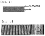
- the Ni layer serves as a protective layer for protecting the Fe layer. This structure is shown in FIG. 1 .
- the outer circumferential surface of a cylindrical body of the battery case is formed through a drawing process.
- the surface roughness of the surface of the battery case is increased to a specific level or higher due to drawing tensile force, whereby the surface of the cylindrical battery case is poor in glossiness.
- this publication does not disclose technology that is capable of improving the corrosion resistance of the battery case by reducing the surface roughness of the battery case.
- Japanese Patent Application Publication No. 2003-263974 discloses a method of manufacturing a cylindrical metal can having a circular cross-sectional shape including a board punching process for punching a metal can material made of a band-type metal sheet in order to form a hexagonal board, a first cup forming process for forming the board into a first intermediate cup body having the cross-sectional shape of a hexagon, a process for drawing the first intermediate cup body, and an ironing process, wherein the drawing process and the ironing process are successively performed (DI processes).
- DI processes drawing process and the ironing process are successively performed
- Japanese Registered Patent No. 4119612 discloses a prismatic battery can configured to receive a power-generating element, configured to constitute a prismatic battery, and configured to have the cross-sectional shape of an appropriate rectangle, wherein the thickness of the short side of the rectangular battery case is greater than the thickness of the long side of the rectangular battery case.
- this patent does not disclose technology that is capable of improving the corrosion resistance of the battery case by reducing the surface roughness of the battery case.
- Japanese Patent Application Publication No. 2009-037980 discloses a method of successively performing a one-stage drawing process and a three-stage ironing process with respect to the intermediate cup body using a drawing and ironing machine.
- this publication does not disclose technology that is capable of improving the corrosion resistance of the battery case by reducing the surface roughness of the battery case.
- a method of manufacturing a cylindrical battery case that is capable of performing an ironing process, which is one of the processes of manufacturing the battery case, a plurality of times in order to decrease the surface roughness of the battery case, thereby improving the corrosion characteristics of the battery case, has not yet been suggested.
- the present invention has been made in view of the above problems and other technical problems that have yet to be resolved.
- the above and other objects can be accomplished by the provision of a method of manufacturing a cylindrical battery case, wherein an ironing process is performed a plurality of times at the time of performing a deep-drawing process for forming the outer circumferential surface of a body of the battery case.
- a primary ironing process may be performed at the time of performing a deep-drawing process for forming the body of the battery case, and a secondary ironing process may be performed at the time of performing a deep-drawing process for forming a step portion at the battery case.
- the surface roughness (Ra) of the battery case after the ironing process may be 0.1 ⁇ m or less.
- the reduction in the thickness of the battery case may be uniform after the ironing process is performed the plurality of times.
- a method of manufacturing a cylindrical battery case including a first step of forming a nickel coating layer on at least one surface of a steel sheet, a second step of thermally treating the steel sheet subjected to the first step in a reducing atmosphere, a third step of blanking and drawing the steel sheet subjected to the second step, a fourth step of performing a primary deep-drawing process and a primary ironing process with respect to the steel sheet subjected to the third step in order to form a body of a battery case, a fifth step of performing a secondary deep-drawing process with respect to the steel sheet subjected to the fourth step in order to form the body of the battery case, a sixth step of performing a tertiary deep-drawing process and a secondary ironing process with respect to the body of the battery case subjected to the fifth step in order to form a step portion at the body of the battery case, and a seventh step of forming a taper and a f
- the surface roughness (Ra) of the battery case after the primary ironing process may be 0.2 ⁇ m or less.
- the surface roughness (Ra) of the battery case after the secondary ironing process may be 0.1 ⁇ m or less.
- a secondary battery including a battery case manufactured using the method of manufacturing the cylindrical battery case.
- a device including the secondary battery.
- the device may be selected from the group consisting of an electronic device, an electric vehicle, a hybrid electric vehicle, and a power storage system.
- FIG. 1 is a conceptual view showing a nickel coating layer of a conventional cylindrical secondary battery.
- a cylindrical secondary battery case is made of a steel sheet having a nickel coating layer formed thereon, i.e. a nickel-plated steel sheet.
- the nickel-plated steel sheet is mainly used as the material for a battery case in which potassium hydroxide, which is strong alkaline, is used as an electrolytic solution, as in an alkaline dry cell or a nickel cadmium storage cell.
- the nickel coating layer exhibits high resistance to alkaline materials, exhibits stable contact resistance when a battery is connected to an external terminal, and exhibits high spot weldability at the time of assembling the battery.
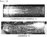
- FIG. 2 is a view showing the results of experiments on the corrosion resistance of the conventional cylindrical secondary battery.
- Tests on the corrosion resistance of a cylindrical secondary battery case are performed under high-temperature and high-humidity conditions.
- the cylindrical secondary battery case was maintained for seven days at a temperature of 60°C and a humidity of 95%RH in order to observe spot corrosion on the surface of the cylindrical secondary battery case.
- spot corrosion was observed on the surface of the cylindrical secondary battery case. Spot corrosion was observed at one or more positions on the surfaces of samples equivalent to 50 to 100% of the total number of samples of the cylindrical secondary battery case.
- a conventional process for manufacturing a battery case of a cylindrical secondary battery may include a step of blanking and drawing a nickel-plated base material (#1) and a step of idling the base material.
- the conventional process for manufacturing the battery case of the cylindrical secondary battery may further include a step of drawing the base material in order to form the battery case (wherein a drawing process is performed four times) (#4 to #7), a step of drawing and body-ironing the base material (#8), a step of drawing the base material (#9), a step of step-drawing the base material (#10), a step of forming a taper and a flange at the base material (#11), a step of forming a vent in the base material (#12), and a step of trimming the base material (#13).
- a non-tubing model of a secondary battery for electric vehicles (EVs) may have relatively low resistance to corrosion.
- electric vehicle manufacturers who use secondary batteries, such as Tesla requires only secondary batteries that satisfy corrosion conditions within the limit after being put in a high-temperature and high-humidity environment (60°C, 95%RH, and 7 days).
- an ironing process which is a method that is capable of highly glossing the surface of a battery case, is performed.
- the surface roughness of a battery case of a cylindrical secondary battery causes a potential difference in metal, whereby an environment in which local corrosion readily occurs is formed.
- the surface area of the battery case may be reduced, whereby the corrosion resistance of the battery case may be improved.
- the ironing process is performed two times. At this time, the final ironing process is performed after the drawing process in order to increase the glossiness.
- the roughness of the battery case is increased and the gloss disappears from the battery case due to the tensile force generated at the side surface of the battery case.
- the thickness of the battery case is decreased and becomes uniform, since the ironing process is performed while pushing the battery case upwards. Consequently, the roughness of the battery case may be decreased and the battery case may have gloss due to compressive friction with a die. That is, the surface roughness of the battery case may be decreased as the extent of ironing of the battery case is increased.
- the present invention provides a method of manufacturing a cylindrical battery case characterized in that an ironing process is performed a plurality of times at the time of performing a deep-drawing process for forming the outer circumferential surface of a body of the battery case.
- a primary ironing process may be performed at the time of performing a deep-drawing process for forming the body of the battery case, and a secondary ironing process may be performed at the time of performing a deep-drawing process for forming a step portion at the battery case.
- the surface roughness Ra of the battery case after the ironing process may be 0.1 ⁇ m or less.
- a reduction in the thickness of the battery case may be uniform after the ironing process is performed the plurality of times.
- the thickness of the battery case is reduced by 0.08 mm.
- the thickness of the battery case is reduced by 0.04 mm every time the ironing process is performed. Eventually, therefore, the thickness of the battery case is reduced by 0.08 mm.
- the reduction in the thickness of the battery case may be uniform irrespective of whether the ironing process is performed only once or a plurality of times.
- the present invention may provide a method of manufacturing a cylindrical battery case including a first step of forming a nickel coating layer on at least one surface of a steel sheet, a second step of thermally treating the steel sheet subjected to the first step in a reducing atmosphere, a third step of blanking and drawing the steel sheet subjected to the second step, a fourth step of performing a primary deep-drawing process and a primary ironing process with respect to the steel sheet subjected to the third step in order to form a body of a battery case, a fifth step of performing a secondary deep-drawing process with respect to the steel sheet subjected to the fourth step in order to form the body of the battery case, a sixth step of performing a tertiary deep-drawing process and a secondary ironing process with respect to the body of the battery case subjected to the fifth step in order to form a step portion at the body of the battery case, and a seventh step of forming a taper and a flange at the body of the battery case
- the method of manufacturing the cylindrical battery case may further include a step of forming a vent in the body of the battery case subjected to the seventh step.
- the method of manufacturing the cylindrical battery case may further include a step of trimming the body of the battery case subjected to the seventh step.
- the surface roughness Ra of the battery case after the primary ironing process may be 0.2 ⁇ m or less.
- the surface roughness Ra of the battery case after the secondary ironing process may be 0.1 ⁇ m or less.
- the present invention may provide a secondary battery including a battery case manufactured using the method of manufacturing the cylindrical battery case.
- the present invention may provide a device including the secondary battery.
- the device may be one selected from the group consisting of an electronic device, an electric vehicle, a hybrid electric vehicle, and a power storage system.
- a step of blanking and drawing a nickel-plated base material (#1) and a step of idling the base material may be performed.
- a cylindrical battery case was manufactured through a step of drawing the base material in order to form the battery case (wherein a drawing process was performed four times) (#4 to #7), a step of drawing and body-ironing the base material (S#8), a step of drawing the base material (#9), a step of step-drawing and body-ironing the base material (#10), a step of forming a taper and a flange at the base material (#11), a step of forming a vent in the base material (#12), and a step of trimming the base material (#13) .
- the ironing process at step #8 was performed in order to reduce the thickness of the base material by 0.04 mm
- the ironing process at step #10 was performed in order to reduce the thickness of the base material by 0.04 mm.
- a cylindrical battery case was manufactured through the same procedure as in Example 1, except that the ironing process at step #8 was performed in order to reduce the thickness of the base material by 0.08 mm and that the body-ironing process at step #10 was omitted.
- Tests on the corrosion resistance of the cylindrical secondary battery cases were performed under high-temperature and high-humidity conditions. Specifically, the cylindrical battery cases were maintained at a temperature of 60°C and a humidity of 95%RH for 7 days, and the external appearances of the cylindrical battery cases were photographed in order to determine whether the surfaces of the cylindrical battery cases were corroded. The results of tests on the corrosion of the cylindrical battery cases are shown in the photograph of FIG. 4 .
- a cylindrical battery case was manufactured through the same procedure as in Comparative Example 1, except that the ironing process at step #8 was performed so as to reduce the thickness of the base material by 0.15 mm.
- a cylindrical battery case was manufactured through the same procedure as in Comparative Example 1, except that the ironing process at step #8 was performed so as to reduce the thickness of the base material by 0.05 mm.
- the surface roughness of the cylindrical battery cases manufactured according to Example 1, Comparative Example 2, and Comparative Example 3 was measured using a surface roughness measuring instrument SJ-411 from Mitutoyo Company. Ra and Rz were measured as the surface roughness, and the 4 mm section of the middle portion of each of the cylindrical battery cases was measured in the height direction (the vertical direction) thereof. The surface roughness of the cylindrical battery cases was measured based on ISO 4287:1997.
- the minimum value, the maximum value, and the average value of the surface roughness Ra of the cylindrical battery case manufactured according to Example 1 were 0.022, 0.040, and 0.03, respectively, and the minimum value, the maximum value, and the average value of the surface roughness Ra of the cylindrical battery case manufactured according to Comparative Example 2 were 0.099, 0.142, and 0.115, respectively.
- the minimum value, the maximum value, and the average value of the surface roughness Ra of the cylindrical battery case manufactured according to Comparative Example 3 were 0.179, 0.309, and 0.236, respectively.
- the minimum value, the maximum value, and the average value of the surface roughness Rz of the cylindrical battery case manufactured according to Example 1 were 0.152, 0.427, and 0.202, respectively, and the minimum value, the maximum value, and the average value of the surface roughness Rz of the cylindrical battery case manufactured according to Comparative Example 2 were 0.542, 0.944, and 0.713, respectively.
- the minimum value, the maximum value, and the average value of the surface roughness Rz of the cylindrical battery case manufactured according to Comparative Example 3 were 0.924, 2.436, and 1.497, respectively.
- a method of manufacturing a cylindrical battery case having reduced surface roughness has the effect of reducing the surface roughness of the cylindrical battery case by performing a thickness reducing process when a process for forming the outer circumferential surface of a body of the cylindrical battery case is performed at the time of manufacturing the cylindrical battery case.
- the method of manufacturing the cylindrical battery case according to the present invention has the effect of improving corrosion characteristics according to the surface roughness.
- a sufficiently coarse surface is formed on the inside of the wall of the cylindrical battery case, and therefore the area of contact between an electrode mixture or an electrode active material, which is received in the cylindrical battery case, and the inner surface of the wall of the cylindrical battery case is increased, whereby it is possible to greatly reduce the internal resistance of a battery.
- the thickness of the wall of the cylindrical battery case is smaller than the thickness of the bottom of the cylindrical battery case as the result of performing the ironing process, whereby it is possible to increase the amount of the electrode mixture or the electrode active material with which the cylindrical battery case is filled and thus to improve the performance of the battery, such as the charging and discharging characteristics of the battery.
Landscapes
- Chemical & Material Sciences (AREA)
- Chemical Kinetics & Catalysis (AREA)
- General Chemical & Material Sciences (AREA)
- Electrochemistry (AREA)
- Engineering & Computer Science (AREA)
- Mechanical Engineering (AREA)
- Manufacturing & Machinery (AREA)
- Inorganic Chemistry (AREA)
- Materials Engineering (AREA)
- Metallurgy (AREA)
- Organic Chemistry (AREA)
- Physics & Mathematics (AREA)
- Thermal Sciences (AREA)
- Crystallography & Structural Chemistry (AREA)
- Sealing Battery Cases Or Jackets (AREA)
Abstract
Description
- This application claims the benefit of Korean Patent Application No.
2017-0137092 filed on October 23, 2017 - The present invention relates to a method of manufacturing a cylindrical battery case, and more particularly to a method of manufacturing a cylindrical battery case that is capable of performing an ironing process, which is one of the processes of manufacturing the battery case, a plurality of times in order to decrease the surface roughness of the battery case, thereby improving the corrosion characteristics of the battery case.
- In general, there are various kinds of secondary batteries, such as a nickel cadmium battery, a nickel hydride battery, a lithium ion battery, and a lithium ion polymer battery. Such secondary batteries have come to be used in large-sized products that require high output, such as an electric vehicle and a hybrid vehicle, a power storage apparatus for storing surplus power or new and renewable energy, and a backup power storage apparatus, as well as small-sized products, such as a digital camera, a portable digital versatile disc (DVD) player, an MP3 player, a cellular phone, a personal digital assistant (PDA), a portable game device, a power tool, and an electric bicycle (E-bike).
- A lithium secondary battery generally includes a positive electrode (cathode), a separator, and a negative electrode (anode), the materials for which are selected in consideration of the lifespan, the charging and discharging capacities, the temperature characteristics, and the stability of the battery.
- Based on the shape of a battery case, secondary batteries are classified into a cylindrical battery, configured to include a cylindrical case, a prismatic battery, configured to include a prismatic case, and a pouch-shaped battery, configured to include a case made of a thin laminate sheet.
- Meanwhile, an electrode assembly, which is a power-generating element configured to have a structure in which a positive electrode, a separator, and a negative electrode are stacked and configured so as to be capable of being charged and discharged, is mounted in the battery case. The electrode assembly is classified as a jelly-roll type electrode assembly, which is configured to have a structure in which a long sheet type positive electrode and a long sheet type negative electrode, to which active materials are applied, are wound in the state in which a separator is interposed between the positive electrode and the negative electrode, or a stacked type electrode assembly, which is configured to have a structure in which a plurality of positive electrodes having a predetermined size and a plurality of negative electrodes having a predetermined size are sequentially stacked in the state in which separators are interposed respectively between the positive electrodes and the negative electrodes.
- Among these electrode assemblies, the jelly-roll type electrode assembly is widely manufactured, since the jelly-roll type electrode assembly is easy to manufacture, has high energy density per unit weight, and can be easily received in a cylindrical battery case.
- Such a cylindrical battery case is generally manufactured as follows. First, a band-type metal battery case material made of a nickel-plated steel sheet is punched in order to form a disk-shaped board corresponding to a desired cylindrical battery case, and a deep-drawing process is performed with respect to the board in order to form a dish-shaped first intermediate cup body. An additional deep-drawing process is performed with respect to the first intermediate cup body in order to form a second intermediate cup body resembling the desired cylindrical battery case. Finally, drawing and ironing processes are performed with respect to the second intermediate cup body in order to form the desired cylindrical battery case.
- A conventional cylindrical battery case is made of a steel sheet manufactured by plating low-carbon steel with Ni. The Ni layer serves as a protective layer for protecting the Fe layer. This structure is shown in
FIG. 1 . - When manufacturing the cylindrical battery case, the outer circumferential surface of a cylindrical body of the battery case is formed through a drawing process. As a result, the surface roughness of the surface of the battery case is increased to a specific level or higher due to drawing tensile force, whereby the surface of the cylindrical battery case is poor in glossiness.
- In addition, various kinds of spot corrosion are observed on the outer circumferential surface of the body of the cylindrical battery case as the result of tests on corrosion resistance. The spot corrosion observed on the outer circumferential surface of the body of the cylindrical battery case is shown in
FIG. 2 . - There have been no attempts to reduce the surface roughness of a cylindrical secondary battery, thereby improving the corrosion resistance of the cylindrical secondary battery and thus improving the corrosion characteristics of the cylindrical secondary battery.
- Meanwhile, Japanese Patent Application Publication No.
2002-015712 - Japanese Patent Application Publication No.
2003-263974 - Japanese Registered Patent No.
4119612 - Japanese Patent Application Publication No.
2009-037980 - That is, a method of manufacturing a cylindrical battery case that is capable of performing an ironing process, which is one of the processes of manufacturing the battery case, a plurality of times in order to decrease the surface roughness of the battery case, thereby improving the corrosion characteristics of the battery case, has not yet been suggested.
- The present invention has been made in view of the above problems and other technical problems that have yet to be resolved.
- The inventors of the present application have conducted a variety of extensive and intensive studies and experiments to solve the problems described above. It is an object of the present invention to provide a method of manufacturing a cylindrical battery case that is capable of solving a problem of relatively low resistance to corrosion of a battery for electric vehicles and improving the corrosion resistance of the cylindrical battery case.
- It is another object of the present invention to provide a method of manufacturing a cylindrical battery case that enables adjustments of the surface roughness of the cylindrical battery case in order to improve the corrosion resistance of the cylindrical battery case.
- It is a further object of the present invention to provide a method of manufacturing a cylindrical battery case that is capable of performing an improved deep-drawing process in order to improve the corrosion resistance of the cylindrical battery case.
- In accordance with an aspect of the present invention, the above and other objects can be accomplished by the provision of a method of manufacturing a cylindrical battery case, wherein an ironing process is performed a plurality of times at the time of performing a deep-drawing process for forming the outer circumferential surface of a body of the battery case.
- A primary ironing process may be performed at the time of performing a deep-drawing process for forming the body of the battery case, and a secondary ironing process may be performed at the time of performing a deep-drawing process for forming a step portion at the battery case.
- The surface roughness (Ra) of the battery case after the ironing process may be 0.1µm or less.
- The reduction in the thickness of the battery case may be uniform after the ironing process is performed the plurality of times.
- In accordance with another aspect of the present invention, there is provided a method of manufacturing a cylindrical battery case, the method including a first step of forming a nickel coating layer on at least one surface of a steel sheet, a second step of thermally treating the steel sheet subjected to the first step in a reducing atmosphere, a third step of blanking and drawing the steel sheet subjected to the second step, a fourth step of performing a primary deep-drawing process and a primary ironing process with respect to the steel sheet subjected to the third step in order to form a body of a battery case, a fifth step of performing a secondary deep-drawing process with respect to the steel sheet subjected to the fourth step in order to form the body of the battery case, a sixth step of performing a tertiary deep-drawing process and a secondary ironing process with respect to the body of the battery case subjected to the fifth step in order to form a step portion at the body of the battery case, and a seventh step of forming a taper and a flange at the body of the battery case subjected to the sixth step.
- The surface roughness (Ra) of the battery case after the primary ironing process may be 0.2µm or less.
- The surface roughness (Ra) of the battery case after the secondary ironing process may be 0.1µm or less.
- In accordance with another aspect of the present invention, there is provided a secondary battery including a battery case manufactured using the method of manufacturing the cylindrical battery case.
- In accordance with a further aspect of the present invention, there is provided a device including the secondary battery.
- The device may be selected from the group consisting of an electronic device, an electric vehicle, a hybrid electric vehicle, and a power storage system.
-
-
FIG. 1 is a conceptual view showing a nickel coating layer of a conventional cylindrical secondary battery. -
FIG. 2 is a view showing the results of experiments on the corrosion resistance of the conventional cylindrical secondary battery. -
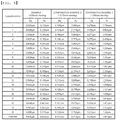
FIG. 3 is a photograph showing the external appearances of cylindrical battery cases according to Example 1 and Comparative Example 1. -
FIG. 4 is a photograph showing the results of tests on the corrosion of the cylindrical battery cases according to Example 1 and Comparative Example 1. -
FIG. 5 is a view showing the surface roughness (Ra, Rz) of cylindrical battery cases according to Example 1, Comparative Example 2, and Comparative Example 3. - Now, preferred embodiments of the present invention will be described in detail with reference to the accompanying drawings such that the preferred embodiments of the present invention can be easily implemented by a person having ordinary skill in the art to which the present invention pertains. In describing the principle of operation of the preferred embodiments of the present invention in detail, however, a detailed description of known functions and configurations incorporated herein will be omitted when the same may obscure the subject matter of the present invention.
- Wherever possible, the same reference numbers will be used throughout the drawings to refer to parts that perform similar functions or operations. Meanwhile, in the case in which one part is 'connected' to another part in the following description of the present invention, not only may the one part be directly connected to the another part, but also, the one part may be indirectly connected to the another part via a further part. In addition, that a certain element is 'included' means that other elements are not excluded, but may be further included, unless mentioned otherwise.
- Reference will now be made in detail to the preferred embodiments of the present invention, examples of which are illustrated in the accompanying drawings.
-
FIG. 1 is a conceptual view showing a nickel coating layer of a conventional cylindrical secondary battery. - As shown in
FIG. 1 , a cylindrical secondary battery case is made of a steel sheet having a nickel coating layer formed thereon, i.e. a nickel-plated steel sheet. - The nickel-plated steel sheet is mainly used as the material for a battery case in which potassium hydroxide, which is strong alkaline, is used as an electrolytic solution, as in an alkaline dry cell or a nickel cadmium storage cell. The nickel coating layer exhibits high resistance to alkaline materials, exhibits stable contact resistance when a battery is connected to an external terminal, and exhibits high spot weldability at the time of assembling the battery.
-
FIG. 2 is a view showing the results of experiments on the corrosion resistance of the conventional cylindrical secondary battery. - Tests on the corrosion resistance of a cylindrical secondary battery case are performed under high-temperature and high-humidity conditions. The cylindrical secondary battery case was maintained for seven days at a temperature of 60°C and a humidity of 95%RH in order to observe spot corrosion on the surface of the cylindrical secondary battery case.
- As the results of the tests, spot corrosion was observed on the surface of the cylindrical secondary battery case. Spot corrosion was observed at one or more positions on the surfaces of samples equivalent to 50 to 100% of the total number of samples of the cylindrical secondary battery case.
- A conventional process for manufacturing a battery case of a cylindrical secondary battery may include a step of blanking and drawing a nickel-plated base material (#1) and a step of idling the base material. In addition, the conventional process for manufacturing the battery case of the cylindrical secondary battery may further include a step of drawing the base material in order to form the battery case (wherein a drawing process is performed four times) (#4 to #7), a step of drawing and body-ironing the base material (#8), a step of drawing the base material (#9), a step of step-drawing the base material (#10), a step of forming a taper and a flange at the base material (#11), a step of forming a vent in the base material (#12), and a step of trimming the base material (#13).
- A non-tubing model of a secondary battery for electric vehicles (EVs) may have relatively low resistance to corrosion. In particular, electric vehicle manufacturers who use secondary batteries, such as Tesla, requires only secondary batteries that satisfy corrosion conditions within the limit after being put in a high-temperature and high-humidity environment (60°C, 95%RH, and 7 days). In order to improve corrosion resistance, therefore, an ironing process, which is a method that is capable of highly glossing the surface of a battery case, is performed.
- The surface roughness of a battery case of a cylindrical secondary battery causes a potential difference in metal, whereby an environment in which local corrosion readily occurs is formed. In the case in which the value of surface roughness Ra is reduced, therefore, the surface area of the battery case may be reduced, whereby the corrosion resistance of the battery case may be improved.
- At the time of deep-drawing the battery case of the cylindrical secondary battery, the ironing process is performed two times. At this time, the final ironing process is performed after the drawing process in order to increase the glossiness.
- In the case in which the drawing process is performed, the roughness of the battery case is increased and the gloss disappears from the battery case due to the tensile force generated at the side surface of the battery case. In the case in which the ironing process is performed, the thickness of the battery case is decreased and becomes uniform, since the ironing process is performed while pushing the battery case upwards. Consequently, the roughness of the battery case may be decreased and the battery case may have gloss due to compressive friction with a die. That is, the surface roughness of the battery case may be decreased as the extent of ironing of the battery case is increased.
- The present invention provides a method of manufacturing a cylindrical battery case characterized in that an ironing process is performed a plurality of times at the time of performing a deep-drawing process for forming the outer circumferential surface of a body of the battery case.
- In addition, a primary ironing process may be performed at the time of performing a deep-drawing process for forming the body of the battery case, and a secondary ironing process may be performed at the time of performing a deep-drawing process for forming a step portion at the battery case.
- In addition, the surface roughness Ra of the battery case after the ironing process may be 0.1µm or less.
- In addition, a reduction in the thickness of the battery case may be uniform after the ironing process is performed the plurality of times.
- It is assumed that, when the ironing process is performed once with respect to the body of the battery case at the deep-drawing step, the thickness of the battery case is reduced by 0.08 mm. In the case in which the ironing process is performed twice, the thickness of the battery case is reduced by 0.04 mm every time the ironing process is performed. Eventually, therefore, the thickness of the battery case is reduced by 0.08 mm.
- That is, the reduction in the thickness of the battery case may be uniform irrespective of whether the ironing process is performed only once or a plurality of times.
- To this end, the present invention may provide a method of manufacturing a cylindrical battery case including a first step of forming a nickel coating layer on at least one surface of a steel sheet, a second step of thermally treating the steel sheet subjected to the first step in a reducing atmosphere, a third step of blanking and drawing the steel sheet subjected to the second step, a fourth step of performing a primary deep-drawing process and a primary ironing process with respect to the steel sheet subjected to the third step in order to form a body of a battery case, a fifth step of performing a secondary deep-drawing process with respect to the steel sheet subjected to the fourth step in order to form the body of the battery case, a sixth step of performing a tertiary deep-drawing process and a secondary ironing process with respect to the body of the battery case subjected to the fifth step in order to form a step portion at the body of the battery case, and a seventh step of forming a taper and a flange at the body of the battery case subjected to the sixth step.
- The method of manufacturing the cylindrical battery case may further include a step of forming a vent in the body of the battery case subjected to the seventh step.
- The method of manufacturing the cylindrical battery case may further include a step of trimming the body of the battery case subjected to the seventh step.
- In addition, the surface roughness Ra of the battery case after the primary ironing process may be 0.2µm or less.
- In addition, the surface roughness Ra of the battery case after the secondary ironing process may be 0.1µm or less.
- In addition, the present invention may provide a secondary battery including a battery case manufactured using the method of manufacturing the cylindrical battery case.
- In addition, the present invention may provide a device including the secondary battery.
- The device may be one selected from the group consisting of an electronic device, an electric vehicle, a hybrid electric vehicle, and a power storage system.
- Hereinafter, the present invention will be described with reference to the following example. This example is provided only for illustration of the present invention and should not be construed as limiting the scope of the present invention.
- In order to manufacture a cylindrical secondary battery according to the present invention, a step of blanking and drawing a nickel-plated base material (#1) and a step of idling the base material may be performed. A cylindrical battery case was manufactured through a step of drawing the base material in order to form the battery case (wherein a drawing process was performed four times) (#4 to #7), a step of drawing and body-ironing the base material (S#8), a step of drawing the base material (#9), a step of step-drawing and body-ironing the base material (#10), a step of forming a taper and a flange at the base material (#11), a step of forming a vent in the base material (#12), and a step of trimming the base material (#13) .
- Specifically, the ironing process at
step # 8 was performed in order to reduce the thickness of the base material by 0.04 mm, and the ironing process atstep # 10 was performed in order to reduce the thickness of the base material by 0.04 mm. - A cylindrical battery case was manufactured through the same procedure as in Example 1, except that the ironing process at
step # 8 was performed in order to reduce the thickness of the base material by 0.08 mm and that the body-ironing process atstep # 10 was omitted. - Referring to
FIG. 3 in connection therewith, it can be seen that, as the results of observing the external appearances of the cylindrical battery case manufactured as described above, the surface glossiness of the cylindrical battery case manufactured according to Example 1 is remarkably higher than the surface glossiness of the cylindrical battery case manufactured according to Comparative Example 1. - Tests on corrosion resistance were performed with respect to the cylindrical battery cases manufactured according to Example 1 and Comparative Example 2.
- Tests on the corrosion resistance of the cylindrical secondary battery cases were performed under high-temperature and high-humidity conditions. Specifically, the cylindrical battery cases were maintained at a temperature of 60°C and a humidity of 95%RH for 7 days, and the external appearances of the cylindrical battery cases were photographed in order to determine whether the surfaces of the cylindrical battery cases were corroded. The results of tests on the corrosion of the cylindrical battery cases are shown in the photograph of
FIG. 4 . - Referring to
FIG. 4 , it can be seen that the cylindrical battery case manufactured according to Example 1 was not corroded but that spot corrosion was observed on the surface of the cylindrical battery case manufactured according to Comparative Example 1. - A cylindrical battery case was manufactured through the same procedure as in Comparative Example 1, except that the ironing process at
step # 8 was performed so as to reduce the thickness of the base material by 0.15 mm. - A cylindrical battery case was manufactured through the same procedure as in Comparative Example 1, except that the ironing process at
step # 8 was performed so as to reduce the thickness of the base material by 0.05 mm. - The surface roughness of the cylindrical battery cases manufactured according to Example 1, Comparative Example 2, and Comparative Example 3 was measured using a surface roughness measuring instrument SJ-411 from Mitutoyo Company. Ra and Rz were measured as the surface roughness, and the 4 mm section of the middle portion of each of the cylindrical battery cases was measured in the height direction (the vertical direction) thereof. The surface roughness of the cylindrical battery cases was measured based on ISO 4287:1997.
- The results of measurement of the surface roughness of the cylindrical battery cases are shown in the table of
FIG. 5 . - Referring to
FIG. 5 , the minimum value, the maximum value, and the average value of the surface roughness Ra of the cylindrical battery case manufactured according to Example 1 were 0.022, 0.040, and 0.03, respectively, and the minimum value, the maximum value, and the average value of the surface roughness Ra of the cylindrical battery case manufactured according to Comparative Example 2 were 0.099, 0.142, and 0.115, respectively. The minimum value, the maximum value, and the average value of the surface roughness Ra of the cylindrical battery case manufactured according to Comparative Example 3 were 0.179, 0.309, and 0.236, respectively. - The minimum value, the maximum value, and the average value of the surface roughness Rz of the cylindrical battery case manufactured according to Example 1 were 0.152, 0.427, and 0.202, respectively, and the minimum value, the maximum value, and the average value of the surface roughness Rz of the cylindrical battery case manufactured according to Comparative Example 2 were 0.542, 0.944, and 0.713, respectively. The minimum value, the maximum value, and the average value of the surface roughness Rz of the cylindrical battery case manufactured according to Comparative Example 3 were 0.924, 2.436, and 1.497, respectively.
- Consequently, it can be seen that the surface roughness of the cylindrical battery case manufactured according to Example 1 is decreased, and therefore it is possible to sufficiently expect an improvement in the corrosion resistance of the cylindrical battery case manufactured according to Example 1 due to the decrease in the surface roughness thereof.
- Those skilled in the art to which the present invention pertains will appreciate that various applications and modifications are possible based on the above description, without departing from the scope of the present invention.
- As is apparent from the above description, a method of manufacturing a cylindrical battery case having reduced surface roughness according to the present invention has the effect of reducing the surface roughness of the cylindrical battery case by performing a thickness reducing process when a process for forming the outer circumferential surface of a body of the cylindrical battery case is performed at the time of manufacturing the cylindrical battery case.
- In addition, the method of manufacturing the cylindrical battery case according to the present invention has the effect of improving corrosion characteristics according to the surface roughness.
- In addition, a sufficiently coarse surface is formed on the inside of the wall of the cylindrical battery case, and therefore the area of contact between an electrode mixture or an electrode active material, which is received in the cylindrical battery case, and the inner surface of the wall of the cylindrical battery case is increased, whereby it is possible to greatly reduce the internal resistance of a battery.
- In addition, in the case in which a conductive agent such as carbon is applied to the inner surface of the wall of the cylindrical battery case, the force of supporting the conductive agent is increased, whereby it is possible to maintain desirable battery characteristics even upon storage for a long time.
- In addition, the thickness of the wall of the cylindrical battery case is smaller than the thickness of the bottom of the cylindrical battery case as the result of performing the ironing process, whereby it is possible to increase the amount of the electrode mixture or the electrode active material with which the cylindrical battery case is filled and thus to improve the performance of the battery, such as the charging and discharging characteristics of the battery.
Claims (10)
- A method of manufacturing a cylindrical battery case, wherein an ironing process is performed a plurality of times at a time of performing a deep-drawing process for forming an outer circumferential surface of a body of the battery case.
- The method according to claim 1, wherein
a primary ironing process is performed at a time of performing a deep-drawing process for forming the body of the battery case, and
a secondary ironing process is performed at a time of performing a deep-drawing process for forming a step portion at the battery case. - The method according to claim 1, wherein a surface roughness Ra of the battery case after the ironing process is 0.1µm or less.
- The method according to claim 1, wherein a reduction in a thickness of the battery case is uniform after the ironing process is performed the plurality of times.
- A method of manufacturing a cylindrical battery case, the method comprising:a first step of forming a nickel coating layer on at least one surface of a steel sheet;a second step of thermally treating the steel sheet subjected to the first step in a reducing atmosphere;a third step of blanking and drawing the steel sheet subjected to the second step;a fourth step of performing a primary deep-drawing process and a primary ironing process with respect to the steel sheet subjected to the third step in order to form a body of a battery case;a fifth step of performing a secondary deep-drawing process with respect to the steel sheet subjected to the fourth step in order to form the body of the battery case;a sixth step of performing a tertiary deep-drawing process and a secondary ironing process with respect to the body of the battery case subjected to the fifth step in order to form a step portion at the body of the battery case; anda seventh step of forming a taper and a flange at the body of the battery case subjected to the sixth step.
- The method according to claim 5, wherein a surface roughness Ra of the battery case after the primary ironing process is 0.2µm or less.
- The method according to claim 5, wherein a surface roughness Ra of the battery case after the secondary ironing process is 0.1µm or less.
- A secondary battery comprising a battery case manufactured using the method of manufacturing the cylindrical battery case according to any one of claims 1 to 7.
- A device comprising the secondary battery according to claim 8.
- The device according to claim 9, wherein the device is selected from a group consisting of an electronic device, an electric vehicle, a hybrid electric vehicle, and a power storage system.
Applications Claiming Priority (2)
| Application Number | Priority Date | Filing Date | Title |
|---|---|---|---|
| KR20170137092 | 2017-10-23 | ||
| PCT/KR2018/012565 WO2019083254A1 (en) | 2017-10-23 | 2018-10-23 | Method for manufacturing cylindrical battery case having improved surface roughness |
Publications (3)
| Publication Number | Publication Date |
|---|---|
| EP3648192A1 true EP3648192A1 (en) | 2020-05-06 |
| EP3648192A4 EP3648192A4 (en) | 2020-07-15 |
| EP3648192B1 EP3648192B1 (en) | 2025-08-27 |
Family
ID=66581760
Family Applications (1)
| Application Number | Title | Priority Date | Filing Date |
|---|---|---|---|
| EP18870614.7A Active EP3648192B1 (en) | 2017-10-23 | 2018-10-23 | Method of manufacturing cylindrical battery case having reduced surface roughness |
Country Status (8)
| Country | Link |
|---|---|
| US (2) | US12091725B2 (en) |
| EP (1) | EP3648192B1 (en) |
| JP (1) | JP7444357B2 (en) |
| KR (1) | KR102252386B1 (en) |
| CN (2) | CN116742102A (en) |
| ES (1) | ES3041341T3 (en) |
| HU (1) | HUE072860T2 (en) |
| PL (1) | PL3648192T3 (en) |
Families Citing this family (3)
| Publication number | Priority date | Publication date | Assignee | Title |
|---|---|---|---|---|
| KR102326468B1 (en) * | 2020-07-17 | 2021-11-16 | (주)동희산업 | Manufacturing method of aluminum battery case for vehicle |
| CN116164616B (en) * | 2022-12-13 | 2024-05-14 | 揭阳市汇宝昌电器有限公司 | A method for detecting key product quality index system of mirror-drawn motor housing |
| KR102826728B1 (en) | 2023-03-29 | 2025-06-30 | 엘지전자 주식회사 | Electronic device and operating method thereof |
Family Cites Families (26)
| Publication number | Priority date | Publication date | Assignee | Title |
|---|---|---|---|---|
| JPH0749296B2 (en) | 1991-12-09 | 1995-05-31 | 東洋鋼鈑株式会社 | Method for manufacturing thinned nickel-plated metal can for battery |
| JP3105785B2 (en) | 1996-05-20 | 2000-11-06 | 東洋鋼鈑株式会社 | Side wall thinned metal can |
| JPH09306439A (en) | 1996-05-21 | 1997-11-28 | Katayama Tokushu Kogyo Kk | Battery can forming material, battery can forming method and battery can |
| JP3671551B2 (en) | 1996-09-10 | 2005-07-13 | 東洋製罐株式会社 | Battery can and method for producing dry battery using the can |
| JPH111779A (en) | 1997-06-11 | 1999-01-06 | Katayama Tokushu Kogyo Kk | Method for manufacturing battery can forming material and battery can forming material manufactured by the method |
| JP3604879B2 (en) | 1997-08-05 | 2004-12-22 | 松下電器産業株式会社 | Battery manufacturing method |
| JP2000011966A (en) | 1998-06-17 | 2000-01-14 | Toyo Seikan Kaisha Ltd | Battery can |
| JP2000021361A (en) | 1998-06-30 | 2000-01-21 | Toyo Rikagaku Kenkyusho:Kk | Manufacture of large capacity battery case |
| US6929880B1 (en) | 1999-05-07 | 2005-08-16 | Matsushita Electric Industrial Co., Ltd. | Square cell container and method of manufacturing the cell container |
| JP2001155698A (en) * | 1999-11-29 | 2001-06-08 | Nec Mobile Energy Kk | Sealed battery |
| JP4064642B2 (en) | 2000-04-28 | 2008-03-19 | 松下電器産業株式会社 | Battery can manufacturing method |
| JP3689679B2 (en) | 2002-03-08 | 2005-08-31 | 松下電器産業株式会社 | Manufacturing method of cylindrical metal can |
| JP4491208B2 (en) | 2003-08-29 | 2010-06-30 | パナソニック株式会社 | Battery can, manufacturing method thereof, and battery |
| JP4839024B2 (en) | 2005-06-22 | 2011-12-14 | パナソニック株式会社 | Battery can and manufacturing method thereof |
| JP2008311198A (en) | 2007-06-18 | 2008-12-25 | Panasonic Corp | Battery can and battery equipped with the same |
| JP2009037680A (en) | 2007-08-01 | 2009-02-19 | Funai Electric Co Ltd | Flat-panel television having dvdloder |
| JP2009037980A (en) | 2007-08-03 | 2009-02-19 | Panasonic Corp | Battery can and metal can blank, and battery can and metal can manufacturing method using the same |
| JP2009113058A (en) | 2007-11-02 | 2009-05-28 | Advan Eng Kk | Method of forming austenitic stainless steel rectangular tube container, forming apparatus and rectangular tube container |
| KR20100097262A (en) | 2009-02-26 | 2010-09-03 | 이성영 | Manufacturing method of case with bottom |
| JP2013518723A (en) | 2010-02-04 | 2013-05-23 | クラウン パッケイジング テクノロジー インコーポレイテッド | Can manufacturing |
| JP5975573B2 (en) | 2013-06-05 | 2016-08-23 | 株式会社神戸製鋼所 | Method for forming a rectangular battery case |
| KR101709560B1 (en) | 2013-09-27 | 2017-02-23 | 주식회사 엘지화학 | Secondary Battery with Electrode Tab Having Low Resistance |
| JP6193794B2 (en) | 2014-03-31 | 2017-09-06 | 株式会社神戸製鋼所 | Method for forming a rectangular battery case |
| JP6030178B2 (en) | 2014-09-18 | 2016-11-24 | 株式会社神戸製鋼所 | Rectangular battery case for in-vehicle battery and manufacturing method thereof |
| KR101621253B1 (en) | 2015-10-21 | 2016-05-16 | 공병인 | A secondary battery case manufacturing method |
| WO2019083254A1 (en) | 2017-10-23 | 2019-05-02 | 주식회사 엘지화학 | Method for manufacturing cylindrical battery case having improved surface roughness |
-
2018
- 2018-10-23 CN CN202310732830.2A patent/CN116742102A/en active Pending
- 2018-10-23 JP JP2019556978A patent/JP7444357B2/en active Active
- 2018-10-23 EP EP18870614.7A patent/EP3648192B1/en active Active
- 2018-10-23 KR KR1020180126665A patent/KR102252386B1/en active Active
- 2018-10-23 CN CN201880024824.9A patent/CN110506344B/en active Active
- 2018-10-23 US US16/606,613 patent/US12091725B2/en active Active
- 2018-10-23 ES ES18870614T patent/ES3041341T3/en active Active
- 2018-10-23 PL PL18870614.7T patent/PL3648192T3/en unknown
- 2018-10-23 HU HUE18870614A patent/HUE072860T2/en unknown
-
2024
- 2024-08-27 US US18/816,132 patent/US20240417821A1/en active Pending
Also Published As
| Publication number | Publication date |
|---|---|
| EP3648192B1 (en) | 2025-08-27 |
| US12091725B2 (en) | 2024-09-17 |
| CN110506344B (en) | 2023-07-14 |
| PL3648192T3 (en) | 2025-11-24 |
| CN110506344A (en) | 2019-11-26 |
| EP3648192A4 (en) | 2020-07-15 |
| CN116742102A (en) | 2023-09-12 |
| JP2020518101A (en) | 2020-06-18 |
| KR20190045082A (en) | 2019-05-02 |
| US20240417821A1 (en) | 2024-12-19 |
| KR102252386B1 (en) | 2021-05-14 |
| ES3041341T3 (en) | 2025-11-11 |
| HUE072860T2 (en) | 2025-12-28 |
| JP7444357B2 (en) | 2024-03-06 |
| US20200335736A1 (en) | 2020-10-22 |
Similar Documents
| Publication | Publication Date | Title |
|---|---|---|
| US20240417821A1 (en) | Cylindrical Battery Case Having Reduced Surface Roughness | |
| KR100471166B1 (en) | Battery and method of manufacturing the same | |
| CN100426558C (en) | Battery can and manufacturing method thereof and battery using the same | |
| US20100190056A1 (en) | Battery Tab Structure | |
| US20090061310A1 (en) | Secondary battery | |
| EP3279966B1 (en) | Method for producing a steel plate for forming a battery can, alkaline battery and a manufacturing method thereof | |
| JPH11120964A (en) | Lithium secondary battery | |
| JP3857818B2 (en) | Lithium ion secondary battery | |
| WO2012064028A3 (en) | Automobile battery and method for manufacturing pole plates | |
| EP4084155A1 (en) | Electrode current collector and secondary battery | |
| JP2014514694A (en) | Electrochemical cell for storing electrical energy | |
| EP4425629A1 (en) | Lithium secondary battery | |
| US20110020691A1 (en) | Alkaline battery | |
| JP2006049237A (en) | Anode material for lithium ion battery | |
| US20250132425A1 (en) | Steel sheet for battery cases and battery case using the same | |
| WO2019083254A1 (en) | Method for manufacturing cylindrical battery case having improved surface roughness | |
| KR20160012771A (en) | Cylindrical battery treated with a step of post-plating process and preparation method thereof | |
| KR101464514B1 (en) | Anode electrode of nickel base secondary battery improving battery service life and electrode structure of nickel base secondary battery including the same | |
| KR100462128B1 (en) | Spirally-rolled electrodes with separator, the batteries therewith, and electrode for batteries | |
| EP4683059A1 (en) | Casing, battery cell, battery, and electric device | |
| EP4683060A1 (en) | Casing, battery cell, battery, and electric device | |
| KR20250166993A (en) | Battery cells, batteries, electrical devices and energy storage devices | |
| JPH1079241A (en) | Battery case | |
| KR100658713B1 (en) | Metal plate for case manufacture of high power secondary battery, metal case for high power secondary battery, and high power secondary battery comprising same | |
| JP2006040674A (en) | Anode material for lithium ion battery |
Legal Events
| Date | Code | Title | Description |
|---|---|---|---|
| STAA | Information on the status of an ep patent application or granted ep patent |
Free format text: STATUS: THE INTERNATIONAL PUBLICATION HAS BEEN MADE |
|
| PUAI | Public reference made under article 153(3) epc to a published international application that has entered the european phase |
Free format text: ORIGINAL CODE: 0009012 |
|
| STAA | Information on the status of an ep patent application or granted ep patent |
Free format text: STATUS: REQUEST FOR EXAMINATION WAS MADE |
|
| 17P | Request for examination filed |
Effective date: 20200129 |
|
| AK | Designated contracting states |
Kind code of ref document: A1 Designated state(s): AL AT BE BG CH CY CZ DE DK EE ES FI FR GB GR HR HU IE IS IT LI LT LU LV MC MK MT NL NO PL PT RO RS SE SI SK SM TR |
|
| AX | Request for extension of the european patent |
Extension state: BA ME |
|
| A4 | Supplementary search report drawn up and despatched |
Effective date: 20200612 |
|
| RIC1 | Information provided on ipc code assigned before grant |
Ipc: B21D 51/16 20060101ALI20200606BHEP Ipc: B21D 22/30 20060101ALI20200606BHEP Ipc: H01M 10/04 20060101ALI20200606BHEP Ipc: H01M 2/02 20060101AFI20200606BHEP |
|
| DAV | Request for validation of the european patent (deleted) | ||
| DAX | Request for extension of the european patent (deleted) | ||
| STAA | Information on the status of an ep patent application or granted ep patent |
Free format text: STATUS: EXAMINATION IS IN PROGRESS |
|
| 17Q | First examination report despatched |
Effective date: 20210326 |
|
| R17C | First examination report despatched (corrected) |
Effective date: 20210326 |
|
| RAP1 | Party data changed (applicant data changed or rights of an application transferred) |
Owner name: LG ENERGY SOLUTION LTD. |
|
| RAP3 | Party data changed (applicant data changed or rights of an application transferred) |
Owner name: LG ENERGY SOLUTION, LTD. |
|
| REG | Reference to a national code |
Ref country code: DE Ref legal event code: R079 Free format text: PREVIOUS MAIN CLASS: H01M0002020000 Ipc: H01M0050150000 Ref country code: DE Ref legal event code: R079 Ref document number: 602018085059 Country of ref document: DE Free format text: PREVIOUS MAIN CLASS: H01M0002020000 Ipc: H01M0050150000 |
|
| RIC1 | Information provided on ipc code assigned before grant |
Ipc: H01M 50/15 20210101AFI20250303BHEP |
|
| GRAP | Despatch of communication of intention to grant a patent |
Free format text: ORIGINAL CODE: EPIDOSNIGR1 |
|
| STAA | Information on the status of an ep patent application or granted ep patent |
Free format text: STATUS: GRANT OF PATENT IS INTENDED |
|
| INTG | Intention to grant announced |
Effective date: 20250417 |
|
| P01 | Opt-out of the competence of the unified patent court (upc) registered |
Free format text: CASE NUMBER: APP_21296/2025 Effective date: 20250506 |
|
| GRAS | Grant fee paid |
Free format text: ORIGINAL CODE: EPIDOSNIGR3 |
|
| GRAA | (expected) grant |
Free format text: ORIGINAL CODE: 0009210 |
|
| STAA | Information on the status of an ep patent application or granted ep patent |
Free format text: STATUS: THE PATENT HAS BEEN GRANTED |
|
| AK | Designated contracting states |
Kind code of ref document: B1 Designated state(s): AL AT BE BG CH CY CZ DE DK EE ES FI FR GB GR HR HU IE IS IT LI LT LU LV MC MK MT NL NO PL PT RO RS SE SI SK SM TR |
|
| REG | Reference to a national code |
Ref country code: GB Ref legal event code: FG4D |
|
| REG | Reference to a national code |
Ref country code: CH Ref legal event code: EP |
|
| REG | Reference to a national code |
Ref country code: DE Ref legal event code: R096 Ref document number: 602018085059 Country of ref document: DE |
|
| REG | Reference to a national code |
Ref country code: IE Ref legal event code: FG4D |
|
| REG | Reference to a national code |
Ref country code: SE Ref legal event code: TRGR |
|
| PGFP | Annual fee paid to national office [announced via postgrant information from national office to epo] |
Ref country code: BE Payment date: 20250922 Year of fee payment: 8 Ref country code: GB Payment date: 20250922 Year of fee payment: 8 |
|
| PGFP | Annual fee paid to national office [announced via postgrant information from national office to epo] |
Ref country code: FR Payment date: 20250925 Year of fee payment: 8 |
|
| PGFP | Annual fee paid to national office [announced via postgrant information from national office to epo] |
Ref country code: SE Payment date: 20250923 Year of fee payment: 8 |
|
| REG | Reference to a national code |
Ref country code: ES Ref legal event code: FG2A Ref document number: 3041341 Country of ref document: ES Kind code of ref document: T3 Effective date: 20251111 |
|
| PGFP | Annual fee paid to national office [announced via postgrant information from national office to epo] |
Ref country code: HU Payment date: 20251029 Year of fee payment: 8 |
|
| REG | Reference to a national code |
Ref country code: HU Ref legal event code: AG4A Ref document number: E072860 Country of ref document: HU |
|
| REG | Reference to a national code |
Ref country code: NL Ref legal event code: MP Effective date: 20250827 |
|
| PG25 | Lapsed in a contracting state [announced via postgrant information from national office to epo] |
Ref country code: IS Free format text: LAPSE BECAUSE OF FAILURE TO SUBMIT A TRANSLATION OF THE DESCRIPTION OR TO PAY THE FEE WITHIN THE PRESCRIBED TIME-LIMIT Effective date: 20251227 |
|
| PGFP | Annual fee paid to national office [announced via postgrant information from national office to epo] |
Ref country code: DE Payment date: 20250922 Year of fee payment: 8 |
|
| PG25 | Lapsed in a contracting state [announced via postgrant information from national office to epo] |
Ref country code: NO Free format text: LAPSE BECAUSE OF FAILURE TO SUBMIT A TRANSLATION OF THE DESCRIPTION OR TO PAY THE FEE WITHIN THE PRESCRIBED TIME-LIMIT Effective date: 20251127 |
|
| REG | Reference to a national code |
Ref country code: LT Ref legal event code: MG9D |
|
| PG25 | Lapsed in a contracting state [announced via postgrant information from national office to epo] |
Ref country code: PT Free format text: LAPSE BECAUSE OF FAILURE TO SUBMIT A TRANSLATION OF THE DESCRIPTION OR TO PAY THE FEE WITHIN THE PRESCRIBED TIME-LIMIT Effective date: 20251229 |
|
| PG25 | Lapsed in a contracting state [announced via postgrant information from national office to epo] |
Ref country code: FI Free format text: LAPSE BECAUSE OF FAILURE TO SUBMIT A TRANSLATION OF THE DESCRIPTION OR TO PAY THE FEE WITHIN THE PRESCRIBED TIME-LIMIT Effective date: 20250827 |
|
| PG25 | Lapsed in a contracting state [announced via postgrant information from national office to epo] |
Ref country code: NL Free format text: LAPSE BECAUSE OF FAILURE TO SUBMIT A TRANSLATION OF THE DESCRIPTION OR TO PAY THE FEE WITHIN THE PRESCRIBED TIME-LIMIT Effective date: 20250827 Ref country code: HR Free format text: LAPSE BECAUSE OF FAILURE TO SUBMIT A TRANSLATION OF THE DESCRIPTION OR TO PAY THE FEE WITHIN THE PRESCRIBED TIME-LIMIT Effective date: 20250827 |
|
| PG25 | Lapsed in a contracting state [announced via postgrant information from national office to epo] |
Ref country code: GR Free format text: LAPSE BECAUSE OF FAILURE TO SUBMIT A TRANSLATION OF THE DESCRIPTION OR TO PAY THE FEE WITHIN THE PRESCRIBED TIME-LIMIT Effective date: 20251128 |
|
| PG25 | Lapsed in a contracting state [announced via postgrant information from national office to epo] |
Ref country code: LV Free format text: LAPSE BECAUSE OF FAILURE TO SUBMIT A TRANSLATION OF THE DESCRIPTION OR TO PAY THE FEE WITHIN THE PRESCRIBED TIME-LIMIT Effective date: 20250827 |
|
| PG25 | Lapsed in a contracting state [announced via postgrant information from national office to epo] |
Ref country code: BG Free format text: LAPSE BECAUSE OF FAILURE TO SUBMIT A TRANSLATION OF THE DESCRIPTION OR TO PAY THE FEE WITHIN THE PRESCRIBED TIME-LIMIT Effective date: 20250827 |
|
| PGFP | Annual fee paid to national office [announced via postgrant information from national office to epo] |
Ref country code: PL Payment date: 20250925 Year of fee payment: 8 |
|
| PG25 | Lapsed in a contracting state [announced via postgrant information from national office to epo] |
Ref country code: RS Free format text: LAPSE BECAUSE OF FAILURE TO SUBMIT A TRANSLATION OF THE DESCRIPTION OR TO PAY THE FEE WITHIN THE PRESCRIBED TIME-LIMIT Effective date: 20251127 |
|
| PGFP | Annual fee paid to national office [announced via postgrant information from national office to epo] |
Ref country code: ES Payment date: 20251117 Year of fee payment: 8 |
|
| REG | Reference to a national code |
Ref country code: AT Ref legal event code: MK05 Ref document number: 1831092 Country of ref document: AT Kind code of ref document: T Effective date: 20250827 |
|
| PG25 | Lapsed in a contracting state [announced via postgrant information from national office to epo] |
Ref country code: RO Free format text: LAPSE BECAUSE OF FAILURE TO SUBMIT A TRANSLATION OF THE DESCRIPTION OR TO PAY THE FEE WITHIN THE PRESCRIBED TIME-LIMIT Effective date: 20250827 |
|
| PG25 | Lapsed in a contracting state [announced via postgrant information from national office to epo] |
Ref country code: SM Free format text: LAPSE BECAUSE OF FAILURE TO SUBMIT A TRANSLATION OF THE DESCRIPTION OR TO PAY THE FEE WITHIN THE PRESCRIBED TIME-LIMIT Effective date: 20250827 |
|
| PG25 | Lapsed in a contracting state [announced via postgrant information from national office to epo] |
Ref country code: DK Free format text: LAPSE BECAUSE OF FAILURE TO SUBMIT A TRANSLATION OF THE DESCRIPTION OR TO PAY THE FEE WITHIN THE PRESCRIBED TIME-LIMIT Effective date: 20250827 |
|
| PG25 | Lapsed in a contracting state [announced via postgrant information from national office to epo] |
Ref country code: AT Free format text: LAPSE BECAUSE OF FAILURE TO SUBMIT A TRANSLATION OF THE DESCRIPTION OR TO PAY THE FEE WITHIN THE PRESCRIBED TIME-LIMIT Effective date: 20250827 |
|
| PG25 | Lapsed in a contracting state [announced via postgrant information from national office to epo] |
Ref country code: IT Free format text: LAPSE BECAUSE OF FAILURE TO SUBMIT A TRANSLATION OF THE DESCRIPTION OR TO PAY THE FEE WITHIN THE PRESCRIBED TIME-LIMIT Effective date: 20250827 |
|
| PG25 | Lapsed in a contracting state [announced via postgrant information from national office to epo] |
Ref country code: CZ Free format text: LAPSE BECAUSE OF FAILURE TO SUBMIT A TRANSLATION OF THE DESCRIPTION OR TO PAY THE FEE WITHIN THE PRESCRIBED TIME-LIMIT Effective date: 20250827 |
|
| PG25 | Lapsed in a contracting state [announced via postgrant information from national office to epo] |
Ref country code: SK Free format text: LAPSE BECAUSE OF FAILURE TO SUBMIT A TRANSLATION OF THE DESCRIPTION OR TO PAY THE FEE WITHIN THE PRESCRIBED TIME-LIMIT Effective date: 20250827 Ref country code: EE Free format text: LAPSE BECAUSE OF FAILURE TO SUBMIT A TRANSLATION OF THE DESCRIPTION OR TO PAY THE FEE WITHIN THE PRESCRIBED TIME-LIMIT Effective date: 20250827 |