EP3647883B1 - Balancier d'une piece d'horlogerie - Google Patents
Balancier d'une piece d'horlogerie Download PDFInfo
- Publication number
- EP3647883B1 EP3647883B1 EP18204358.8A EP18204358A EP3647883B1 EP 3647883 B1 EP3647883 B1 EP 3647883B1 EP 18204358 A EP18204358 A EP 18204358A EP 3647883 B1 EP3647883 B1 EP 3647883B1
- Authority
- EP
- European Patent Office
- Prior art keywords
- balance
- recess
- timepiece
- recesses
- opening
- Prior art date
- Legal status (The legal status is an assumption and is not a legal conclusion. Google has not performed a legal analysis and makes no representation as to the accuracy of the status listed.)
- Active
Links
Images

Classifications
-
- G—PHYSICS
- G04—HOROLOGY
- G04B—MECHANICALLY-DRIVEN CLOCKS OR WATCHES; MECHANICAL PARTS OF CLOCKS OR WATCHES IN GENERAL; TIME PIECES USING THE POSITION OF THE SUN, MOON OR STARS
- G04B17/00—Mechanisms for stabilising frequency
-
- G—PHYSICS
- G01—MEASURING; TESTING
- G01M—TESTING STATIC OR DYNAMIC BALANCE OF MACHINES OR STRUCTURES; TESTING OF STRUCTURES OR APPARATUS, NOT OTHERWISE PROVIDED FOR
- G01M1/00—Testing static or dynamic balance of machines or structures
- G01M1/30—Compensating imbalance
- G01M1/32—Compensating imbalance by adding material to the body to be tested, e.g. by correcting-weights
-
- G—PHYSICS
- G04—HOROLOGY
- G04B—MECHANICALLY-DRIVEN CLOCKS OR WATCHES; MECHANICAL PARTS OF CLOCKS OR WATCHES IN GENERAL; TIME PIECES USING THE POSITION OF THE SUN, MOON OR STARS
- G04B17/00—Mechanisms for stabilising frequency
- G04B17/04—Oscillators acting by spring tension
- G04B17/06—Oscillators with hairsprings, e.g. balance
- G04B17/063—Balance construction
-
- G—PHYSICS
- G04—HOROLOGY
- G04B—MECHANICALLY-DRIVEN CLOCKS OR WATCHES; MECHANICAL PARTS OF CLOCKS OR WATCHES IN GENERAL; TIME PIECES USING THE POSITION OF THE SUN, MOON OR STARS
- G04B17/00—Mechanisms for stabilising frequency
- G04B17/20—Compensation of mechanisms for stabilising frequency
-
- G—PHYSICS
- G04—HOROLOGY
- G04B—MECHANICALLY-DRIVEN CLOCKS OR WATCHES; MECHANICAL PARTS OF CLOCKS OR WATCHES IN GENERAL; TIME PIECES USING THE POSITION OF THE SUN, MOON OR STARS
- G04B17/00—Mechanisms for stabilising frequency
- G04B17/20—Compensation of mechanisms for stabilising frequency
- G04B17/28—Compensation of mechanisms for stabilising frequency for the effect of imbalance of the weights, e.g. tourbillon
-
- G—PHYSICS
- G04—HOROLOGY
- G04B—MECHANICALLY-DRIVEN CLOCKS OR WATCHES; MECHANICAL PARTS OF CLOCKS OR WATCHES IN GENERAL; TIME PIECES USING THE POSITION OF THE SUN, MOON OR STARS
- G04B18/00—Mechanisms for setting frequency
- G04B18/006—Mechanisms for setting frequency by adjusting the devices fixed on the balance
-
- G—PHYSICS
- G04—HOROLOGY
- G04B—MECHANICALLY-DRIVEN CLOCKS OR WATCHES; MECHANICAL PARTS OF CLOCKS OR WATCHES IN GENERAL; TIME PIECES USING THE POSITION OF THE SUN, MOON OR STARS
- G04B18/00—Mechanisms for setting frequency
- G04B18/04—Adjusting the beat of the pendulum, balance, or the like, e.g. putting into beat
-
- G—PHYSICS
- G04—HOROLOGY
- G04D—APPARATUS OR TOOLS SPECIALLY DESIGNED FOR MAKING OR MAINTAINING CLOCKS OR WATCHES
- G04D7/00—Measuring, counting, calibrating, testing or regulating apparatus
- G04D7/08—Measuring, counting, calibrating, testing or regulating apparatus for balance wheels
- G04D7/082—Measuring, counting, calibrating, testing or regulating apparatus for balance wheels for balancing
- G04D7/088—Measuring, counting, calibrating, testing or regulating apparatus for balance wheels for balancing by loading the balance wheel itself with material
-
- G—PHYSICS
- G04—HOROLOGY
- G04D—APPARATUS OR TOOLS SPECIALLY DESIGNED FOR MAKING OR MAINTAINING CLOCKS OR WATCHES
- G04D7/00—Measuring, counting, calibrating, testing or regulating apparatus
- G04D7/12—Timing devices for clocks or watches for comparing the rate of the oscillating member with a standard
- G04D7/1257—Timing devices for clocks or watches for comparing the rate of the oscillating member with a standard wherein further adjustment devices are present
-
- G—PHYSICS
- G04—HOROLOGY
- G04D—APPARATUS OR TOOLS SPECIALLY DESIGNED FOR MAKING OR MAINTAINING CLOCKS OR WATCHES
- G04D7/00—Measuring, counting, calibrating, testing or regulating apparatus
- G04D7/12—Timing devices for clocks or watches for comparing the rate of the oscillating member with a standard
- G04D7/1257—Timing devices for clocks or watches for comparing the rate of the oscillating member with a standard wherein further adjustment devices are present
- G04D7/1271—Timing devices for clocks or watches for comparing the rate of the oscillating member with a standard wherein further adjustment devices are present for the control mechanism only (from outside the clockwork)
- G04D7/1292—Timing devices for clocks or watches for comparing the rate of the oscillating member with a standard wherein further adjustment devices are present for the control mechanism only (from outside the clockwork) whereby the adjustment device works on the balance wheel
Definitions
- the invention relates to a balance wheel of a timepiece and to a method of adjusting the rate of the timepiece.
- a resonator typically includes a sprung balance.
- This sprung balance is the true heart of mechanical movements in timepieces since it regulates the passage of time through its oscillations and is responsible for the precision of such pieces.
- the oscillation period of a sprung balance depends in particular on the inertia of the balance and the rigidity of the balance spring. This period is affected by many secondary phenomena, in particular by the variation in the rigidity of the balance spring depending on the temperature, by variations in air friction on the balance, by the existence of an unbalance on the balance or by the play existing at the pivots of the balance spring axis.
- a deviation of the order of a few seconds per day is generally tolerated for a timepiece equipped with a mechanical movement; however, all of the aforementioned secondary phenomena must be scrupulously controlled during the manufacture of the resonator or the casing of the watch movement.
- the inertia and unbalance of the balance wheel are adjusted by removing material through machining during several successive measurement and machining steps in order to tighten the isochronism curves of the resonator as much as possible.
- the rate changes significantly when the movement is cased. due to the constraints generated on the movement by the casing or due to aerodynamic modifications induced by a closed environment of the case. It is therefore necessary to carry out a final adjustment to precisely adjust the running of the movement after casing this movement.
- This final adjustment can be done in different ways, in particular by adjusting the position of the weights arranged on the balance, by adjusting the active length of the balance spring by means of an index system, by removing material from the balance using a laser source or by adding material by projection onto the balance.
- adjusting the position of the weights or the active length of the balance spring is a delicate operation for an operator and difficult to automate.
- the index system is likely to become out of adjustment over time, particularly in the event of an impact.
- the ablation of material by laser degrades the aesthetic appearance of the balance wheel and can cause deposits of calcined material in the movement.
- the addition of material by spraying the material in liquid form using an automated process carried out in particular by an Aerosol Jet type printer can cause splashes, resulting from the impact of the material on the balance wheel, which can spread and contaminate the watch movement.
- WO2018015071 A1 describes a clock balance in which flared recesses are made to accommodate masses of material.
- An aim of the invention is therefore to propose a balance wheel of a resonator of the sprung balance type adapted for precise adjustment of the rate of the movement by projection of material and optimized to compensate including the problem of splashes that can spread into the movement.
- Another aim of the invention is to propose a method for adjusting a timepiece comprising a resonator equipped with the balance wheel according to the invention.
- the application step comprises a sub-step of projecting the material into one or more of these recesses.
- the projection sub-step comprises a phase of selective projection of the material into one or more of these recesses.
- one or more types of material are projected onto the balance.
- the method comprises a step of arranging a watch movement comprising the balance wheel in a caseband of a case of the timepiece.
- the invention also relates to a timepiece comprising such a balance wheel.
- the invention relates to a balance wheel 10 of a resonator 120 of the sprung balance type of a watch movement 110 of a timepiece 100 visible in the figure 11 .
- a balance 10 is provided with at least one recess 15 provided to receive a projected material for carrying out an adjustment of the rate of the timepiece 100 and therefore of its movement 110.
- a recess 15 of the balance 10 also called a groove or cavity, is adapted to receive a projection of material during a method of adjusting the rate of this timepiece 100 described below.
- the balance 10 comprises at least one recess 15.
- a recess 15 may be a groove, a cavity or even a concave structure, being provided with an opening 15a, a solid bottom 15b which may have a substantially flat surface as well as an internal wall 15c connecting said opening 15a to said bottom 15b.
- a solid bottom should be understood here as being a bottom without an opening/orifice.
- this recess 15 may be a through hole by forming a through hole then comprising an opening and a bottom forming/comprising in whole or in part an orifice/opening.
- the recess 15 can be defined in the felloe 11 or one of the arms 13 of the balance 10.
- the balance 10 comprises several recesses 15, these can be distributed only in the arms 13 of this balance 10 or only in the felloe 11 or in the arms 13 and the felloe 11 of this balance 10.
- the balance 10 comprises a recess 15, this can be defined in the adjustment face 14 over the entire contour of the felloe 11. This latter configuration makes it possible in particular to ensure adjustment of the rate of the movement by a more effective correction of the unbalance of the balance because in this context the movement is already in a vertical position for the rate measurements, therefore less handling.
- the effect of the correction made is accentuated in comparison with a balance whose recess(es) are defined in other parts of the adjustment face 14 of the felloe 11, because in this alternative the deposition of material is carried out as far as possible from the axis of rotation of the balance with in addition less material. added for the same correction or obtaining a greater correction for the same quantity of material added.
- Such a recess 15 can be produced in the balance 10 from milling operations and/or deep laser engraving.
- This recess 15 can also be produced during a three-dimensional manufacturing operation of the balance 10 (for example by DRIE printing or engraving, or laser exposure and wet engraving) or of the serge or arms that constitute it or from an assembly operation of two layers of parts, one of which has a through hole.
- This assembly operation can implement a technique of the “wafer bonding” type or even double-sided deep reactive ion etching processes, ultrasonic welding or pin driving or even screwing, etc.
- each recess 15 and therefore each corresponding interior volume is intended to receive a projection of material in order to modify the inertia of the balance 10.
- this projected material can be in the liquid, pasty or solid state and can comprise an adhesive, a paint or a metal suspension.
- Such a material is in the present embodiment preferably a material in liquid form/state.
- the felloe 11 comprises several recesses 15, for example three recesses 15, distributed around the periphery of the felloe 11 defined in the part 14a of the adjustment face 14. Each recess 15 extends along an arc of a circle with an angle of, for example, between 5° and 120° and preferably between 30° and 60°.
- the felloe 11 comprises a multitude of recesses 15, for example four or more recesses 15, which are distributed around the periphery of this felloe 11. These recesses 15 extend along an arc of a circle with an angle of less than 90° and preferably less than 5°.
- the recesses 15 can for example be distributed over this periphery of the rim 11 of the balance 10 in a regular manner so as to obtain a symmetrical distribution of the material projected into all the recesses or some of them in order to modify the inertia of the balance 10 without modifying its center of mass during the last adjustment, thus contributing to precisely adjusting the rate of the movement 110.
- the recesses 15 according to the two aforementioned embodiments can, according to another example, be distributed over the periphery of the rim 11 in an asymmetrical manner in order to modify the inertia of the balance 10 and its center of mass by projection of material into all the asymmetrical recesses or some of them.
- the recesses 15 of the balance 10 are distributed symmetrically on the rim 11 of the balance 10 and the material can be projected only into some of these recesses 15 which have an asymmetrical configuration relative to each other.
- the recess 15 has a specific shape so as to contain in its internal volume any splashes resulting from the impact of the material projected against its bottom 15b and thus prevent the contamination of the watch movement 110 during a final adjustment necessary to precisely adjust the running of the movement once it has been arranged/driven into a caseband of the timepiece 100.
- the recesses 15 in this balance 10 have a generally concave shape and can be of two types depending on whether they belong to a first or a second variant of recess 15.
- the bottom 15b of the latter is at most partially visible from a position defined above its opening 15a.
- the position is here “a point of view” which is arranged above the adjustment face 14 of the balance 10 and preferably on a central axis 17a of the opening 15a visible on the figure 3 .
- This position is similar to that of an outlet orifice of a device intended to project the material into this recess 15. It is therefore understood that the production of such a recess 15 can therefore provide for configuring the opening 15a relative to the corresponding bottom 15b of the recess 15.
- the opening 15a of this recess 15 may comprise an edge defining an access space comprising a surface which is less than or substantially less than a surface of the bottom 15b of the recess 15.
- the central axes 17a, 17b of the bottom 15b and of the opening 15a and therefore of their respective surfaces are preferably merged.
- the recess 15 extends in a direction 18 forming with the central axis 17a of the opening 15a an acute angle ⁇ .
- the opening 15a of this recess 15 is arranged in an offset manner relative to the bottom 15b so that this bottom 15b is at most partially visible from the position defined above this opening 15a.
- the central axes 17a, 17b of the bottom 15b and of the opening 15a and therefore of their respective surfaces, are not merged.
- the recess 15 comprises an internal wall 15c provided with a bulge 19 extending substantially horizontally or horizontally in whole or in part over a portion of a surface of said wall 15c.
- This bulge 19 may be integral with the internal wall 15c or be an added part (for example a screw) arranged in the internal volume of the recess 15. It is understood that this bulge 19 is defined to partially conceal/mask the bottom 15b of the recess 15 so that this bottom 15b is at most partially visible from the position defined above this opening 15a.
- the recess 15 has a section of essentially rectangular, square, circular, or trapezoidal shape. This section, otherwise called vertical cross section, is included in a vertical transverse plane which is perpendicular to the adjustment face 14 of the balance 10.
- the bottom 15b has a gap with said opening 15a which is greater or substantially greater than the largest geometric dimension of its bottom 15b.
- This gap corresponds to the depth of the recess 15 and the largest geometric dimension can here be a length when this bottom 15b has an essentially rectangular shape or even a diameter if the shape of this bottom 15b is substantially circular.
- the recess 15 has a vertical cross section of essentially flared, rectangular or circular shape.
- the recess 15 opens onto the adjustment face 14 of the balance 10, this face 14 being intended to be arranged opposite the back of the case of the timepiece 100 when the watch movement 110 is mounted in this case.
- the material projection device may for example be an Aerosol Jet type printer which allows very precise projection with a very small volume of material.
- the invention also relates to a method for adjusting the rate of the watch movement 110.
- This method comprises a step 20 of arranging the watch movement 110 comprising the balance 10 in the case middle of the case of the timepiece 100. Subsequently, the method provides a step 21 of measuring the rate of this watch movement 110 thus arranged in the case middle.
- This measurement can preferably be carried out without contact given that access to the resonator is particularly narrow. In a known manner, the measurement of the rate of the movement can thus be carried out, for example, in optical or acoustic form.
- This measuring step 21 makes it possible to compare the measured rate with a desired rate. Furthermore, it also makes it possible to know the beat of the balance 10 in order to be able to synchronize it with the projection of material in order to precisely deposit the material in the recess 15 or in each recess 15 of the balance 10.
- this method comprises a step 23 of applying the material in one or more recesses of the balance 10 in order to modify the inertia of the balance 10 according to the correction value.
- the recess(es) 15 may be located either only on the felloe 11 or at least one arm 13, or on the felloe 11 and on one or more arms 13 of the balance 10 or in the contour of the felloe 11 defined in the adjustment face.
- Such a step 23 comprises a sub-step 24 of projecting the material into one or more recesses of the balance 10. This sub-step 24 makes it possible to avoid any mechanical contact with the balance 10 as part of the adjustment of the rate.
- the balance 10 Since the adjustment of the rate according to this method only allows the increase of the inertia of the balance 10, the balance 10 is manufactured so as to have a mass deficit so that the watch movement 110 has a rate advance which will be corrected during this sub-step of projection 24 of material in all the recesses 15 of this balance 10 or in some of them.
- the correction value may correspond to a projection of the material into several recesses 15 of the balance 10 so as to obtain a symmetrical distribution of the projected material in order to modify the inertia of the balance 10 without modifying its center of mass.
- the recesses of the balance 10 are distributed symmetrically in particular on the rim 11 of the balance 10 and the quantity of projected material is identical for each recess 15 so as not to create an imbalance.
- the correction value is determined by comparing, on the one hand, the measured rate and, on the other hand, the desired unbalance and frequency for the resonator 120.
- the correction value corresponds to the asymmetric distribution of the addition of material by projection in recesses 15 of the balance 10 distributed symmetrically on the rim 11 of the balance 10.
- the recesses 15 of the balance 10 are distributed symmetrically on the rim 11 of the balance 10 and the material is projected only into some of these recesses 15 which have an asymmetrical configuration with respect to each other.
- the projection sub-step 24 comprises a phase of selective projection of the material into one or more of these recesses 15.
- the projection substep 24 may advantageously be carried out using an Aerosol Jet printer, any other maskless projection or printing technology is also possible.
- the material deposited in all or some of the recesses 15 may comprise an adhesive, paint or metal suspension.
Landscapes
- Physics & Mathematics (AREA)
- General Physics & Mathematics (AREA)
- Electric Clocks (AREA)
- Electromechanical Clocks (AREA)
- Piezo-Electric Or Mechanical Vibrators, Or Delay Or Filter Circuits (AREA)
Description
- L'invention se rapporte à un balancier d'une pièce d'horlogerie ainsi qu'à un procédé de réglage de la marche de la pièce d'horlogerie.
- Dans une pièce d'horlogerie un résonateur comprend classiquement un balancier-spiral. Ce balancier-spiral est le véritable cœur des mouvements mécaniques dans les pièces d'horlogerie puisqu'il régule la marche du temps grâce à ses oscillations et est responsable de la précision de telles pièces. La période d'oscillation d'un balancier-spiral dépend en particulier de l'inertie du balancier et de la rigidité du spiral. Cette période est affectée par de nombreux phénomènes secondaires, notamment par la variation de rigidité du spiral en fonction de la température, par les variations des frottements de l'air sur le balancier, par l'existence d'un balourd sur le balancier ou encore par les jeux existants au niveau des pivots de l'axe du balancier-spiral. Il est généralement toléré d'une pièce d'horlogerie équipée d'un mouvement mécanique une déviation de l'ordre de quelques secondes par jour cependant tous les phénomènes secondaires précités doivent être maîtrisés scrupuleusement lors de la fabrication du résonateur ou encore d'emboîtage du mouvement horloger.
- Traditionnellement, l'inertie et le balourd du balancier sont ajustés, en enlevant de la matière par usinage au cours de plusieurs étapes de mesure et d'usinage successives afin de resserrer au maximum les courbes d'isochronisme du résonateur. Il a été toutefois constaté que la marche change sensiblement au moment de l'emboîtage du mouvement à cause des contraintes générées sur le mouvement par l'emboîtage ou encore du fait de modifications aérodynamiques induites par un environnement fermé de la boîte. Il est donc nécessaire d'effectuer un dernier réglage pour ajuster de manière précise la marche du mouvement après emboîtage de ce mouvement. Ce dernier réglage peut se faire de différentes façons, en particulier par un réglage de la position de masselottes agencées sur le balancier, par un réglage de la longueur active du spiral au moyen d'un système de raquetterie, par l'ablation de matière du balancier au moyen d'une source laser ou encore par l'ajout de matière par projection sur le balancier.
- Ces différentes façons de procéder à ce dernier réglage présentent toutefois plusieurs inconvénients.
- Par exemple, le réglage de la position des masselottes ou de la longueur active du spiral est une opération délicate pour un opérateur et difficile à automatiser. Par ailleurs, le système de raquetterie est susceptible de se dérégler au cours du temps, notamment en cas de choc. L'ablation de matière par laser dégrade l'aspect esthétique du balancier et peut provoquer des dépôts de matière calcinée dans le mouvement. Enfin, l'ajout de matière par projection de la matière sous forme liquide selon un procédé automatisé réalisé notamment par une imprimante du type Aerosol Jet peut provoquer des éclaboussures, résultant de l'impact de la matière sur le balancier, qui peuvent se répandre et contaminer le mouvement horloger.
- Le document
WO2018015071 A1 décrit un balancier horloger dans lequel des évidements évasés sont pratiqués pour accueillir des masses de matière. - Un but de l'invention est par conséquent de proposer un balancier d'un résonateur du type balancier-spiral adapté pour un réglage précis de la marche du mouvement par projection de matière et optimisé pour pallier notamment le problème des éclaboussures pouvant se répandre dans le mouvement.
- Un autre but de l'invention est de proposer un procéder de réglage d'une pièce d'horlogerie comportant un résonateur équipé du balancier selon l'invention.
- Dans ce dessein, l'invention concerne un balancier d'une pièce d'horlogerie comprenant une face de réglage pourvue d'au moins un évidement prévu pour recevoir une matière projetée pour une réalisation d'un réglage de la marche de ladite pièce d'horlogerie par la modification de l'inertie et du balourd du balancier, ledit évidement comprenant une ouverture et un fond, dans ce balancier :
- ledit fond étant tout au plus partiellement visible d'une position définie au-dessus de ladite ouverture notamment sur un axe central de l'ouverture.
- Dans d'autres modes de réalisation :
- l'ouverture est configurée dans la face de réglage relativement au fond dudit évidement rendant ledit fond tout au plus partiellement visible de ladite position ;
- l'ouverture comprend un bord définissant une surface qui est inférieure ou sensiblement inférieure à une surface du fond de l'évidement ;
- l'évidement s'étend selon une direction formant avec l'axe central de l'ouverture un angle aigu ;
- l'évidement présente une section transversale verticale de forme essentiellement évasée, rectangulaire ou encore circulaire ;
- l'évidement présente une section transversale verticale de forme essentiellement rectangulaire, carrée, circulaire, ou encore trapézoïdale ;
- l'évidement comprend une paroi interne pourvue d'un renflement s'étendant sensiblement horizontalement ou horizontalement en tout ou partie sur une portion d'une surface de ladite paroi ;
- balancier comprend une serge, un moyeu destiné à être monté pivotant sur un axe de balancier, et au moins un bras reliant la serge au moyeu, la serge du balancier comportant ledit au moins un évidement ;
- balancier comprend plusieurs bras dont au moins un comprend ledit au moins un évidement ;
- plusieurs évidements sont répartis de manière régulière ou irrégulière sur le pourtour de la serge, et
- au moins trois évidements sont repartis régulièrement sur le pourtour de la serge, chaque évidement s'étendant selon un arc de cercle d'un angle variant entre 20° et 90°, de préférence entre 40° et 60°.
- L'invention concerne aussi un procédé de réglage de la marche d'une pièce d'horlogerie comprenant ce balancier, le procédé comportant les étapes suivantes :
- mesure de la marche de la pièce d'horlogerie ;
- détermination d'une valeur de correction à appliquer à l'inertie et/ou au balourd du balancier pour obtenir une marche corrigée de ladite pièce d'horlogerie, et
- application d'une matière dans un ou plusieurs évidements agencés sur le balancier afin de modifier l'inertie du balancier selon ladite valeur de correction.
- Avantageusement, l'étape d'application comprend une sous-étape de projection de la matière dans un ou plusieurs de ces évidements.
- En particulier, la sous-étape de projection comprend une phase de projection sélective de la matière dans un ou plusieurs de ces évidements.
- Avantageusement encore, lors de la sous-étape de projection un ou plusieurs types de matière sont projetés sur le balancier.
- En outre, le procédé comprend une étape d'agencement d'un mouvement horloger comprenant le balancier dans une carrure d'une boîte de la pièce d'horlogerie.
- L'invention concerne également une pièce d'horlogerie comportant un tel balancier.
- D'autres particularités et avantages ressortiront clairement de la description qui en est faite ci-après, à titre indicatif et nullement limitatif, en référence aux figures annexées, dans lesquelles :
- la
figure 1 est une vue de dessus d'un balancier comportant trois évidements, selon un mode de réalisation de l'invention ; - la
figure 2 est une vue de dessus du balancier comportant quatre évidements, selon le mode de réalisation de l'invention ; - les
figures 3 à 6 représentent des premières variantes de l'évidement comprenant chacune un fond qui est tout au plus partiellement visible d'une position définie au-dessus d'une ouverture de cet évidement, selon le mode de réalisation de l'invention ; - les
figures 7 et8 représentent des variantes non comprises dans l'invention. - les
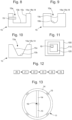
figures 9 et 10 représentent des deuxièmes variantes de l'évidement comprenant chacune un fond présentant un écart avec une ouverture de cet évidement qui est supérieur ou sensiblement supérieur à la plus grande dimension géométrique dudit fond, selon des variantes qui ne sont pas comprises dans l'invention telle que revendiquée ; - la
figure 11 représente une pièce d'horlogerie comprenant un tel balancier, selon le mode de réalisation de l'invention ; - la
figure 12 représente un logigramme relatif à un procédé de réglage de la marche de la pièce d'horlogerie, selon le mode de réalisation de l'invention, et - la
figure 13 est une vue de dessus du balancier comportant deux bras et quatre évidements, selon le mode de réalisation de l'invention. - En référence aux
figures 1 à10 et 13 , l'invention porte sur un balancier 10 d'un résonateur 120 du type balancier-spiral d'un mouvement horloger 110 d'une pièce d'horlogerie 100 visible sur lafigure 11 . Un tel balancier 10 est pourvu d'au moins un évidement 15 prévu pour recevoir une matière projetée pour une réalisation d'un réglage de la marche de la pièce d'horlogerie 100 et donc de son mouvement 110. Un tel évidement 15 du balancier 10 encore appelé gorge ou cavité, est adapté pour recevoir une projection de matière au cours d'un procédé de réglage de la marche de cette pièce d'horlogerie 100 décrit par la suite. - A cet effet sur les
figures 1, 2 et13 , le balancier 10 comporte une serge 11, un moyeu 12 destiné à être monté pivotant sur un axe de balancier 16, et un ou plusieurs bras 13, par exemple deux, trois ou quatre bras 13, reliant la serge 11 au moyeu 12. Le balancier 10 comprend une face de réglage 14 qui est plane ou sensiblement plane, et s'étendant dans un plan orthogonal à l'axe de balancier 16. Cette face de réglage 14 est orientée vers le fond du boîtier de la pièce d'horlogerie 100 lorsque le balancier 10 est compris dans un mouvement horloger 110 qui est monté dans ce boîtier. Cette face de réglage 14 comprend une première partie 14a comprise/définie dans la serge 11 du balancier 10 et une deuxième partie 14b dans les bras 13 de ce balancier 10. - Ainsi que nous l'avons déjà évoqué, le balancier 10 comprend au moins un évidement 15. Un tel évidement 15 peut être une gorge, une cavité ou encore une structure concave, en étant pourvu d'une ouverture 15a, d'un fond plein 15b pouvant avoir une surface sensiblement plane ainsi que d'une paroi interne 15c reliant ladite ouverture 15a audit fond 15b. Un fond plein doit être entendu ici comme étant un fond dépourvu d'ouverture/d'orifice. Dans une variante, cet évidement 15 peut être traversant en formant un trou traversant comprenant alors une ouverture et un fond formant/comprenant en tout ou partie un orifice/une ouverture. L'évidement 15 peut être défini dans la serge 11 ou l'un des bras 13 du balancier 10. Lorsque le balancier 10 comporte plusieurs évidements 15, ceux-ci peuvent être répartis uniquement dans les bras 13 de ce balancier 10 ou uniquement dans la serge 11 ou alors dans les bras 13 et la serge 11 de ce balancier 10. Alternativement, lorsque le balancier 10 comprend un évidement 15 celui-ci peut être défini dans la face de réglage 14 sur tout le contour de la serge 11. Cette dernière configuration permet notamment d'assurer un réglage de la marche du mouvement par une correction plus efficace du balourd du balancier du fait que dans ce contexte le mouvement est déjà en position verticale pour les mesures de marche donc moins de manipulations. De plus, l'effet de la correction apportée est accentué en comparaison avec un balancier dont le ou les évidements sont définis dans d'autres parties de la face de réglage 14 de la serge 11, car dans cette alternative le dépôt de matière est effectué au plus loin de l'axe de rotation du balancier avec en plus moins de matière ajoutée pour une même correction ou une obtention d'une correction plus importante pour la même quantité de matière ajoutée.
- Un tel évidement 15 peut être réalisé dans le balancier 10 à partir d'opérations de fraisage et/ou de gravure profonde par laser. Cet évidement 15 peut aussi être réalisé lors d'une opération de fabrication en trois dimensions du balancier 10 (par exemple par impression ou gravure DRIE, ou encore insolation laser et gravure humide) ou encore de la serge ou des bras qui le constituent ou encore à partir d'une opération d'assemblage de deux couches de pièces dont l'une comporte un trou traversant. Cette opération d'assemblage peut mettre en œuvre une technique du type « wafer bonding » ou encore des procédés de gravure ionique réactive profonde double face, de soudure par ultrasons ou de chassage par goupilles ou encore de vissage, etc...
- Dans des exemples illustrés sur les
figures 1 et 2 où des évidements 15 sont définis uniquement dans la partie 14a de la face de réglage 14 du balancier 10, c'est-à-dire uniquement dans la serge 11, cette dernière comporte alors plusieurs ouvertures 15a donnant accès à un volume intérieur des évidements 15 correspondants. Dans cette configuration, chaque évidement 15 et donc chaque volume intérieur correspondant, est destiné à recevoir une projection de matière afin de modifier l'inertie du balancier 10. De manière non limitative, cette matière projetée peut être à l'état liquide, pâteux ou solide et peut comprendre une colle, une peinture ou une suspension de métal. Une telle matière est dans le présent mode de réalisation de préférence une matière sous forme/à l'état liquide. On notera de plus que cette matière peut être durcissable lorsqu'elle est exposée par exemple à une source froide ou encore à une source de chaleur susceptible de coopérer avec un dispositif de ventilation. De manière alternative, lorsque cette matière projetée est à l'état solide en comprenant par exemple une encre comportant de l'argent, du tungstène ou encore du carbure de tungstène sous forme de flocons ou de morceaux, elle ne requiert aucun traitement ultérieur particulier après sa projection sur le balancier 10. - Sur
figure 1 , la serge 11 comporte plusieurs évidements 15, par exemple trois évidements 15, répartis sur le pourtour de la serge 11 défini dans la partie 14a de la face de réglage 14. Chaque évidement 15 s'étend selon un arc de cercle d'un angle compris par exemple entre 5° et 120° et de préférence compris entre 30° et 60°. Sur lafigure 2 , la serge 11 comporte une multitude d'évidements 15, par exemple quatre évidements 15 ou plus, qui sont répartis sur le pourtour de cette serge 11. Ces évidements 15 s'étendent selon un arc de cercle d'un angle inférieur à 90° et de préférence inférieur à 5°. - Dans ces deux formes d'exécution, les évidements 15 peuvent par exemple être répartis sur ce pourtour de la serge 11 du balancier 10 de manière régulière de sorte à obtenir une distribution symétrique de la matière projetée dans tous les évidements ou certains d'entre eux afin de modifier l'inertie du balancier 10 sans modifier son centre de masse au cours du dernier réglage contribuant ainsi à ajuster de manière précise la marche du mouvement 110. Les évidements 15 selon les deux formes d'exécution précitées peuvent, selon un autre exemple, être répartis sur le pourtour de la serge 11 de manière asymétrique afin de modifier l'inertie du balancier 10 et son centre de masse par projection de matière dans tous les évidements asymétriques ou certains d'entre eux. Dans un autre exemple, les évidements 15 du balancier 10 sont répartis de manière symétrique sur la serge 11 du balancier 10 et la matière peut être projetée uniquement dans certains de ces évidements 15 qui présentent une configuration asymétrique les uns par rapport aux autres.
- De manière avantageuse, l'évidement 15 présente une forme spécifique de sorte à contenir dans son volume intérieur d'éventuelles éclaboussures résultant de l'impact de la matière projetée contre son fond 15b et empêcher ainsi la contamination du mouvement horloger 110 au cours d'un dernier réglage nécessaire pour ajuster de manière précise la marche du mouvement une fois celui-ci agencé/chassé dans une carrure de la pièce d'horlogerie 100.
- Les évidements 15 dans ce balancier 10 présentent une forme générale concave et peuvent être de deux types selon qu'elles appartiennent à une première ou une deuxième variante d'évidement 15. Dans la première variante d'évidement 15 visible sur les
figures 3 à 6 le fond 15b de ce dernier est tout au plus partiellement visible d'une position définie au-dessus de son ouverture 15a. La position est ici « un point de vue » qui est agencé au-dessus de la face de réglage 14 du balancier 10 et préférentiellement sur un axe central 17a de l'ouverture 15a visible sur lafigure 3 . Cette position est similaire à celle d'un orifice de sortie d'un dispositif prévu pour projeter la matière dans cet évidement 15. On comprend donc que la réalisation d'un tel évidement 15 peut prévoir donc de configurer l'ouverture 15a relativement au fond 15b correspondant de l'évidement 15. - Dans la variante des
figures 3 à 6 , l'ouverture 15a de cet évidement 15 peut comprendre un bord définissant un espace d'accès comprenant une surface qui est inférieure ou sensiblement inférieure à une surface du fond 15b de l'évidement 15. Dans cette configuration, les axes centraux 17a, 17b du fond 15b et de l'ouverture 15a et donc de leurs surfaces respectives, sont de préférence confondus. Ainsi une partie plus ou moins grande du fond 15b de l'évidement 15 est alors masqué par le bord de l'ouverture 15a. Dans une autre variante illustrée sur lafigure 7 , l'évidement 15 s'étend selon une direction 18 formant avec l'axe central 17a de l'ouverture 15a un angle α aigu. Autrement dit, l'ouverture 15a de cet évidement 15 est agencée de manière décalée par rapport au fond 15b de manière à ce que ce fond 15b soit tout au plus partiellement visible de la position définie au-dessus de cette ouverture 15a. Dans cette configuration, les axes centraux 17a, 17b du fond 15b et de l'ouverture 15a et donc de leurs surfaces respectives, sont non-confondus. Dans une autre variante non comprise dans l'invention telle que revendiquée et visible sur lafigure 8 , l'évidement 15 comprend une paroi interne 15c pourvue d'un renflement 19 s'étendant sensiblement horizontalement ou horizontalement en tout ou partie sur une portion d'une surface de ladite paroi 15c. Ce renflement 19 peut être venu de matière avec la paroi interne 15c ou être une pièce rapportée (par exemple une vis) agencée dans le volume intérieur de l'évidement 15. On comprend que ce renflement 19 est défini pour occulter/masquer partiellement le fond 15b de l'évidement 15 afin que ce fond 15b soit tout au plus partiellement visible de la position définie au-dessus de cette ouverture 15a. - Dans cette première variante, l'évidement 15 présente une section de forme essentiellement rectangulaire, carrée, circulaire, ou encore trapézoïdale. Cette section autrement appelée section transversale verticale est comprise dans un plan transversal vertical qui est perpendiculaire à la face de réglage 14 du balancier 10.
- Dans une autre variante non comprise dans l'invention telle que revendiquée et visible sur les
figures 9 et 10 , le fond 15b présente un écart avec ladite ouverture 15a qui est supérieur ou sensiblement supérieur à la plus grande dimension géométrique de son fond 15b. Cet écart correspond à la profondeur de l'évidement 15 et la plus grande dimension géométrique peut être ici une longueur lorsque ce fond 15b à une forme essentiellement rectangulaire ou encore un diamètre si la forme de ce fond 15b est substantiellement circulaire. Dans cette variante, l'évidement 15 présente une section transversale verticale de forme essentiellement évasée, rectangulaire ou encore circulaire. - On notera que la forme de la section de ces deux variantes de l'évidement 15 participe notamment à :
- confiner les éclaboussures éventuelles subséquentes à la projection de matière ;
- définir géométriquement la position du dépôt de matière sur la face de réglage 14 ;
- améliorer l'esthétique du dépôt de matière sur la face de réglage 14 ;
- faciliter l'adhérence du dépôt de matière sur la face de réglage 14, indépendamment de la préparation de face de réglage 14 ;
- protéger le dépôt de matière d'éventuels coups de brucelles qui peuvent survenir lors des manipulations du mouvement horloger 110.
- Dans ce contexte, l'évidement 15 débouche sur la face de réglage 14 du balancier 10, cette face 14 étant destinée à être agencée en regard du fond du boîtier de la pièce d'horlogerie 100 lorsque que le mouvement horloger 110 est monté dans ce boîtier. Selon cet agencement, il est par conséquent possible de faire un dernier réglage de la marche du mouvement horloger 110 lorsqu'il est monté dans la carrure de la pièce d'horlogerie 100, avant l'assemblage du fond du boîtier avec la carrure, en ajustant le dispositif de projection de matière au-dessus du balancier 10 tout en s'assurant que la masse oscillante de cette pièce d'horlogerie 100 est dégagée du résonateur du mouvement 110 pour un mouvement du type automatique. Le dispositif de projection de matière peut par exemple être une imprimante du type Aerosol Jet qui autorise une projection très précise avec un très faible volume de matière.
- En référence à la
figure 12 , l'invention concerne également un procédé de réglage de la marche du mouvement horloger 110. Ce procédé comprend une étape d'agencement 20 du mouvement horloger 110 comprenant le balancier 10 dans la carrure de la boîte de la pièce d'horlogerie 100. Par la suite le procédé prévoit une étape de mesure 21 de la marche de ce mouvement horloger 110 ainsi disposé dans la carrure. Cette mesure peut être réalisée de préférence sans contact étant donné que l'accès au résonateur est particulièrement étroit. De manière connue, la mesure de la marche du mouvement peut ainsi être réalisée, par exemple, sous forme optique ou acoustique. Cette étape de mesure 21 permet de comparer la marche mesurée avec une marche souhaitée. D'autre part, elle permet également de connaître le battement du balancier 10 afin de pouvoir le synchroniser avec la projection de matière pour déposer précisément la matière dans l'évidement 15 ou dans chaque évidement 15 du balancier 10. - Le procédé comprend ensuite une étape de détermination 22 de la valeur de correction à appliquer à l'inertie du balancier 10 pour obtenir une marche corrigée. Cette valeur de correction est déterminée par les formules connues suivantes :
- Pour un résonateur du type balancier-spiral, le moment d'inertie l du balancier répond à la formule :

- dans laquelle m représente la masse du balancier 10 et r son rayon de giration qui dépend également de la température par l'intermédiaire du coefficient de dilatation du balancier 10.
- De plus, le couple élastique C du spiral à section constante répond à la formule :

- Enfin, la fréquence f du résonateur 120 comprenant le balancier-spiral répond à la formule:

- Ensuite, ce procédé comprend une étape d'application 23 de la matière dans un ou plusieurs évidements du balancier 10 afin de modifier l'inertie du balancier 10 selon la valeur de correction. Le ou les évidements 15 peuvent se trouver soit uniquement sur la serge 11 ou au moins un bras 13, soit sur la serge 11 et sur un ou plusieurs bras 13 du balancier 10 ou soit dans le contour de la serge 11 défini dans la face de réglage . Une telle étape 23 comprend une sous-étape de projection 24 de la matière dans un ou plusieurs évidements du balancier 10. Cette sous-étape 24 permet d'éviter tout contact mécanique avec le balancier 10 dans le cadre du réglage de la marche.
- On notera que cette sous-étape de projection 24 peut être précédée d'une sous-étape de retrait du balancier 10 du mouvement horloger 100 par exemple lorsque ce balancier 10 comprend un ou plusieurs évidements 15 correspondant au trou traversant. Dans ce contexte, la projection de matière dans ce trou traversant est alors réalisée hors du mouvement 110 avec l'utilisation :
- d'un support appliqué par exemple sur une face du balancier 10 comportant le fond de cet évidement 15 pourvu de l'orifice et/ou
- d'une matière projetée présentant un indice de viscosité élevé.
- Étant donné que le réglage de la marche selon ce procédé ne permet que l'augmentation de l'inertie du balancier 10, le balancier 10 est fabriqué de sorte à avoir un déficit de masse afin que le mouvement horloger 110 présente une avance de marche qui sera corrigée au cours de cette sous-étape de projection 24 de matière dans tous les évidements 15 de ce balancier 10 ou dans certains d'entre eux.
- Selon une forme d'exécution, la valeur de correction peut correspondre à une projection de la matière dans plusieurs évidements 15 du balancier 10 de sorte à obtenir une distribution symétrique de la matière projetée afin de modifier l'inertie du balancier 10 sans modifier son centre de masse. Dans ce cas, les évidements du balancier 10 sont répartis de manière symétrique notamment sur la serge 11 du balancier 10 et la quantité de matière projetée est identique pour chaque évidement 15 afin de ne pas créer de balourd.
- Selon une forme d'exécution, la valeur de correction est déterminée en comparant, d'une part, la marche mesurée et, d'autre part, le balourd et la fréquence souhaités pour le résonateur 120. Dans ce cas, la valeur de correction correspond à la distribution asymétrique de l'ajout de matière par projection dans des évidements 15 du balancier 10 répartis de manière symétrique sur la serge 11 du balancier 10. Alternativement, les évidements 15 du balancier 10 sont répartis de manière symétrique sur la serge 11 du balancier 10 et la matière est projetée uniquement dans certains de ces évidements 15 qui présentent une configuration asymétrique les uns par rapport aux autres. Dans un tel contexte, la sous-étape de projection 24 comprend une phase de projection sélective de la matière dans un ou plusieurs de ces évidements 15.
- En complément, on notera que lors de la sous-étape de projection 24 un ou plusieurs types de matière sont projetés sur le balancier 10. Ainsi les évidements 15 d'un même balancier 10 peuvent :
- comprendre la même matière projetée, ou
- comprendre chacune une matière projetée différente de celles de tous les autres évidements de ce balancier 10 ou d'au moins un des autres évidements 15 de ce balancier 10.
- Bien que la sous-étape de projection 24 puisse être avantageusement réalisée en utilisant une imprimante Aerosol Jet, toute autre technologie de projection ou d'impression sans masque est également possible. Ainsi que nous l'avons déjà évoqué, la matière déposée dans tous les évidements 15 ou dans certains d'entre eux peut comporter une colle, une peinture ou une suspension de métal.
- Préférentiellement, la sous-étape de projection 24 de matière peut être suivie d'une sous-étape de solidification 25 de la matière projetée et ce, notamment si la matière est à l'état liquide ou pâteux. Cette sous-étape 25 peut, suivant la matière utilisée, consister à évaporer un solvant, thermo-durcir la matière ou réticuler la matière dans l'évidement. Un polymère peut également être déposé dans l'évidement 15 ou chaque évidement 15 du balancier 10 puis réticulé au moyen d'un rayonnement ultra-violet.
Claims (16)
- Balancier (10) d'une pièce d'horlogerie (100) comprenant une face de réglage (14) pourvue d'au moins un évidement (15) prévu pour recevoir une matière projetée pour une réalisation d'un réglage de la marche de ladite pièce d'horlogerie (100) par la modification de l'inertie et du balourd du balancier (10), ledit évidement (15) comprenant une ouverture (15a) et un fond (15b), caractérisé en ce que ledit fond (15b) est tout au plus partiellement visible d'une position définie au-dessus de ladite ouverture (15a).
- Balancier (10) selon la revendication 1, caractérisé en ce que l'ouverture (15a) est configurée dans la face de réglage (14) relativement au fond (15b) dudit évidement (15) rendant ledit fond (15b) tout au plus partiellement visible de ladite position.
- Balancier (10) selon l'une quelconque des revendications 1 et 2, caractérisé en ce que l'ouverture (15a) comprend un bord définissant une surface qui est inférieure ou sensiblement inférieure à une surface du fond (15b) de l'évidement.
- Balancier (10) selon l'une quelconque des revendications 1 et 2, caractérisé en ce que l'évidement (15) s'étend selon une direction (18) formant avec l'axe central (17a) de l'ouverture (15a) un angle (α) aigu.
- Balancier (10) selon l'une quelconque des revendications 1, 2 et 3, caractérisé en ce que l'évidement (15) présente une section transversale verticale de forme essentiellement rectangulaire, carrée, circulaire, ou encore trapézoïdale.
- Balancier (10) selon l'une quelconque des revendications 1 à 2 et 4, caractérisé en ce que l'évidement (15) comprend une paroi interne (15c) pourvue d'un renflement (19) s'étendant sensiblement horizontalement ou horizontalement en tout ou partie sur une portion d'une surface de ladite paroi (15c).
- Balancier selon l'une quelconque des revendications précédentes, caractérisé en ce qu'il comprend une serge (11), un moyeu (12) destiné à être monté pivotant sur un axe de balancier (16), et au moins un bras (13) reliant la serge (11) au moyeu (12), la serge (11) du balancier (16) comportant ledit au moins un évidement (15).
- Balancier (10) selon l'une quelconque des revendications précédentes, caractérisé en ce qu'il comprend plusieurs bras (13) dont au moins un comprend ledit au moins un évidement.
- Balancier (10) selon la revendication 8, caractérisé en ce que plusieurs évidements (15) sont répartis de manière régulière ou irrégulière sur le pourtour de la serge (11).
- Balancier (10) selon l'une quelconque des revendications 7 et 9, caractérisé en ce qu'au moins trois évidements (15) sont repartis régulièrement sur le pourtour de la serge (11), chaque évidement (15) s'étendant selon un arc de cercle d'un angle variant entre 20° et 90°, de préférence entre 40° et 60°.
- Procédé de réglage de la marche d'une pièce d'horlogerie (100) comprenant un balancier (10) selon l'une quelconque des revendications précédentes, le procédé comportant les étapes suivantes :- mesure (21) de la marche de la pièce d'horlogerie ;- détermination (22) d'une valeur de correction à appliquer à l'inertie et/ou au balourd du balancier (10) pour obtenir une marche corrigée de ladite pièce d'horlogerie (100), et- application (23) d'une matière dans un ou plusieurs évidements agencés sur le balancier (10) afin de modifier l'inertie du balancier (10) selon ladite valeur de correction.
- Procédé selon la revendication précédente, caractérisé en ce que l'étape d'application comprend une sous-étape de projection (24) de la matière dans un ou plusieurs de ces évidements.
- Procédé selon la revendication précédente, caractérisé en ce que la sous-étape de projection (24) comprend une phase de projection (26) sélective de la matière dans un ou plusieurs de ces évidements (15).
- Procédé selon l'une quelconque des revendications 12 et 13, caractérisé en ce que lors de la sous-étape de projection (24) un ou plusieurs types de matière sont projetés sur le balancier (10).
- Procédé selon l'une quelconque des revendications 11 à 13, caractérisé en ce qu'il comprend une étape d'agencement (20) d'un mouvement horloger (110) comprenant le balancier (10) dans une carrure d'une boîte de la pièce d'horlogerie (100).
- Pièce d'horlogerie (100) comportant un balancier (10) selon l'une quelconque des revendications 1 à 10.
Priority Applications (4)
| Application Number | Priority Date | Filing Date | Title |
|---|---|---|---|
| EP18204358.8A EP3647883B1 (fr) | 2018-11-05 | 2018-11-05 | Balancier d'une piece d'horlogerie |
| US16/671,313 US11720062B2 (en) | 2018-11-05 | 2019-11-01 | Balance of a timepiece |
| CN201911074961.6A CN111142353B (zh) | 2018-11-05 | 2019-11-05 | 钟表的摆轮 |
| JP2019200500A JP6960973B2 (ja) | 2018-11-05 | 2019-11-05 | 時計のテンプ |
Applications Claiming Priority (1)
| Application Number | Priority Date | Filing Date | Title |
|---|---|---|---|
| EP18204358.8A EP3647883B1 (fr) | 2018-11-05 | 2018-11-05 | Balancier d'une piece d'horlogerie |
Publications (2)
| Publication Number | Publication Date |
|---|---|
| EP3647883A1 EP3647883A1 (fr) | 2020-05-06 |
| EP3647883B1 true EP3647883B1 (fr) | 2025-01-01 |
Family
ID=64172376
Family Applications (1)
| Application Number | Title | Priority Date | Filing Date |
|---|---|---|---|
| EP18204358.8A Active EP3647883B1 (fr) | 2018-11-05 | 2018-11-05 | Balancier d'une piece d'horlogerie |
Country Status (4)
| Country | Link |
|---|---|
| US (1) | US11720062B2 (fr) |
| EP (1) | EP3647883B1 (fr) |
| JP (1) | JP6960973B2 (fr) |
| CN (1) | CN111142353B (fr) |
Families Citing this family (1)
| Publication number | Priority date | Publication date | Assignee | Title |
|---|---|---|---|---|
| JP7588724B2 (ja) * | 2020-12-17 | 2024-11-22 | セー エス ウー エム・サントル・スイス・デレクトロニク・エ・ドゥ・ミクロテクニク・エス アー・ルシェルシュ・エ・デヴェロプマン | 計時器部品上に機能的要素を印刷する方法 |
Family Cites Families (11)
| Publication number | Priority date | Publication date | Assignee | Title |
|---|---|---|---|---|
| ATE396430T1 (de) | 2004-02-05 | 2008-06-15 | Montres Breguet Sa | Unruh für uhrwerk |
| US8240910B2 (en) * | 2006-12-21 | 2012-08-14 | Complitime S.A. | Mechanical oscillator for timepiece |
| CH714952B1 (fr) | 2007-05-08 | 2019-10-31 | Patek Philippe Sa Geneve | Composant horloger, son procédé de fabrication et application de ce procédé. |
| CN101378327A (zh) | 2007-08-29 | 2009-03-04 | 中国移动通信集团公司 | 通信网络系统和通信网络业务处理方法 |
| EP2104005A1 (fr) * | 2008-03-20 | 2009-09-23 | Nivarox-FAR S.A. | Balancier composite et son procédé de fabrication |
| EP2677369B1 (fr) * | 2010-06-11 | 2015-01-14 | Montres Breguet SA | Balancier haute fréquence pour pièce d'horlogerie |
| EP2420900B1 (fr) * | 2010-08-06 | 2019-02-27 | DAMASKO GmbH | Oscillateur, système oscillant mécanique pour montres-bracelet dotées d'un tel oscillateur et montre dotée d'un tel système oscillant |
| CH705928B1 (fr) * | 2011-12-22 | 2016-09-15 | Nivarox Far Sa | Procédé d'amélioration du pivotement d'un balancier, balancier, balancier-spiral, mouvement et pièce d'horlogerie. |
| JP2015143673A (ja) * | 2013-12-27 | 2015-08-06 | セイコーインスツル株式会社 | てんぷ、ムーブメント、および時計 |
| CH711766B1 (fr) * | 2015-11-13 | 2019-08-15 | Nivarox Sa | Balancier à réglage d'inertie. |
| EP3273312A1 (fr) * | 2016-07-18 | 2018-01-24 | ETA SA Manufacture Horlogère Suisse | Procédé de réglage de la marche d'une pièce d'horlogerie |
-
2018
- 2018-11-05 EP EP18204358.8A patent/EP3647883B1/fr active Active
-
2019
- 2019-11-01 US US16/671,313 patent/US11720062B2/en active Active
- 2019-11-05 JP JP2019200500A patent/JP6960973B2/ja active Active
- 2019-11-05 CN CN201911074961.6A patent/CN111142353B/zh active Active
Also Published As
| Publication number | Publication date |
|---|---|
| EP3647883A1 (fr) | 2020-05-06 |
| JP2020076775A (ja) | 2020-05-21 |
| JP6960973B2 (ja) | 2021-11-05 |
| US11720062B2 (en) | 2023-08-08 |
| US20200142359A1 (en) | 2020-05-07 |
| CN111142353A (zh) | 2020-05-12 |
| CN111142353B (zh) | 2022-06-03 |
Similar Documents
| Publication | Publication Date | Title |
|---|---|---|
| EP2485095B1 (fr) | Balancier composite | |
| EP2145237B1 (fr) | Composant horloger et son procédé de fabrication | |
| EP2196868B1 (fr) | Spiral à élévation de courbe en matériau à base de silicium | |
| EP1445670A1 (fr) | Spiral de résonateur balancier-spiral et son procédé de fabrication | |
| EP1986059A1 (fr) | Dispositif de pivotement d'un arbre dans une pièce d'horlogerie | |
| WO2012010410A1 (fr) | Balancier a reglage d'inertie avec insert | |
| CA2813691A1 (fr) | Outillage d'enrobage de la pale d'une aube de turbine pour l'usinage du pied comportant un berceau mobile en rotation | |
| CH702708B1 (fr) | Ensemble oscillateur balancier-spiral avec éléments détachables et procédé d'ajustement de sa fréquence d'oscillation. | |
| EP4264378B1 (fr) | Procede d'impression d'un element fonctionnel sur un composant horloger | |
| EP3647883A1 (fr) | Balancier d'une piece d'horlogerie | |
| CH715513A2 (fr) | Balancier d'une pièce d'horlogerie. | |
| EP2917792B1 (fr) | Mise d'inertie ou d'équilibrage d'un ensemble balancier-spiral d'horlogerie | |
| CH712711B1 (fr) | Procédé de réglage de la marche d'une pièce d'horlogerie. | |
| EP2506093B1 (fr) | Balancier pour mouvement d'horlogerie | |
| EP3485334B1 (fr) | Procédé de règlage de la marche d'une pièce d'horlogerie | |
| EP3391154B1 (fr) | Système oscillant pour montre | |
| EP3037893A1 (fr) | Composant micromécanique ou horloger à guidage flexible | |
| EP4432020A1 (fr) | Mouvement horloger | |
| CH695395A5 (fr) | Spiral de résonateur balancier-spiral. | |
| EP3637196B1 (fr) | Oscillateur mécanique | |
| CH698837B1 (fr) | Spiral de résonateur balancier-spiral et son procédé de fabrication. | |
| EP1213628A1 (fr) | Procédé de réglage de la fréquence d'oscillation d'un balancier-spiral pour une pièce d'horlogerie mécanique | |
| CH718184A2 (fr) | Procédé d'impression d'un élément fonctionnel sur un composant horloger. | |
| EP4564105A1 (fr) | Procédé de fabrication d'un balancier | |
| CH720571A2 (fr) | Procédé de fabrication d'un oscillateur horloger à pivot flexible |
Legal Events
| Date | Code | Title | Description |
|---|---|---|---|
| PUAI | Public reference made under article 153(3) epc to a published international application that has entered the european phase |
Free format text: ORIGINAL CODE: 0009012 |
|
| STAA | Information on the status of an ep patent application or granted ep patent |
Free format text: STATUS: THE APPLICATION HAS BEEN PUBLISHED |
|
| AK | Designated contracting states |
Kind code of ref document: A1 Designated state(s): AL AT BE BG CH CY CZ DE DK EE ES FI FR GB GR HR HU IE IS IT LI LT LU LV MC MK MT NL NO PL PT RO RS SE SI SK SM TR |
|
| AX | Request for extension of the european patent |
Extension state: BA ME |
|
| STAA | Information on the status of an ep patent application or granted ep patent |
Free format text: STATUS: REQUEST FOR EXAMINATION WAS MADE |
|
| 17P | Request for examination filed |
Effective date: 20201106 |
|
| RBV | Designated contracting states (corrected) |
Designated state(s): AL AT BE BG CH CY CZ DE DK EE ES FI FR GB GR HR HU IE IS IT LI LT LU LV MC MK MT NL NO PL PT RO RS SE SI SK SM TR |
|
| STAA | Information on the status of an ep patent application or granted ep patent |
Free format text: STATUS: EXAMINATION IS IN PROGRESS |
|
| 17Q | First examination report despatched |
Effective date: 20220623 |
|
| P01 | Opt-out of the competence of the unified patent court (upc) registered |
Effective date: 20230611 |
|
| GRAP | Despatch of communication of intention to grant a patent |
Free format text: ORIGINAL CODE: EPIDOSNIGR1 |
|
| STAA | Information on the status of an ep patent application or granted ep patent |
Free format text: STATUS: GRANT OF PATENT IS INTENDED |
|
| INTG | Intention to grant announced |
Effective date: 20240809 |
|
| GRAS | Grant fee paid |
Free format text: ORIGINAL CODE: EPIDOSNIGR3 |
|
| RIN1 | Information on inventor provided before grant (corrected) |
Inventor name: CONUS, THIERRY Inventor name: DUPAS, EMMANUEL Inventor name: MAIER, FREDERIC Inventor name: LANI, SEBASTIEN |
|
| GRAA | (expected) grant |
Free format text: ORIGINAL CODE: 0009210 |
|
| STAA | Information on the status of an ep patent application or granted ep patent |
Free format text: STATUS: THE PATENT HAS BEEN GRANTED |
|
| AK | Designated contracting states |
Kind code of ref document: B1 Designated state(s): AL AT BE BG CH CY CZ DE DK EE ES FI FR GB GR HR HU IE IS IT LI LT LU LV MC MK MT NL NO PL PT RO RS SE SI SK SM TR |
|
| REG | Reference to a national code |
Ref country code: GB Ref legal event code: FG4D Free format text: NOT ENGLISH |
|
| REG | Reference to a national code |
Ref country code: DE Ref legal event code: R096 Ref document number: 602018078072 Country of ref document: DE |
|
| REG | Reference to a national code |
Ref country code: CH Ref legal event code: EP |
|
| REG | Reference to a national code |
Ref country code: IE Ref legal event code: FG4D Free format text: LANGUAGE OF EP DOCUMENT: FRENCH |
|
| REG | Reference to a national code |
Ref country code: LT Ref legal event code: MG9D |
|
| REG | Reference to a national code |
Ref country code: NL Ref legal event code: MP Effective date: 20250101 |
|
| REG | Reference to a national code |
Ref country code: AT Ref legal event code: MK05 Ref document number: 1756872 Country of ref document: AT Kind code of ref document: T Effective date: 20250101 |
|
| PG25 | Lapsed in a contracting state [announced via postgrant information from national office to epo] |
Ref country code: NL Free format text: LAPSE BECAUSE OF FAILURE TO SUBMIT A TRANSLATION OF THE DESCRIPTION OR TO PAY THE FEE WITHIN THE PRESCRIBED TIME-LIMIT Effective date: 20250101 |
|
| PG25 | Lapsed in a contracting state [announced via postgrant information from national office to epo] |
Ref country code: FI Free format text: LAPSE BECAUSE OF FAILURE TO SUBMIT A TRANSLATION OF THE DESCRIPTION OR TO PAY THE FEE WITHIN THE PRESCRIBED TIME-LIMIT Effective date: 20250101 |
|
| PG25 | Lapsed in a contracting state [announced via postgrant information from national office to epo] |
Ref country code: PL Free format text: LAPSE BECAUSE OF FAILURE TO SUBMIT A TRANSLATION OF THE DESCRIPTION OR TO PAY THE FEE WITHIN THE PRESCRIBED TIME-LIMIT Effective date: 20250101 |
|
| PG25 | Lapsed in a contracting state [announced via postgrant information from national office to epo] |
Ref country code: ES Free format text: LAPSE BECAUSE OF FAILURE TO SUBMIT A TRANSLATION OF THE DESCRIPTION OR TO PAY THE FEE WITHIN THE PRESCRIBED TIME-LIMIT Effective date: 20250101 |
|
| PG25 | Lapsed in a contracting state [announced via postgrant information from national office to epo] |
Ref country code: NO Free format text: LAPSE BECAUSE OF FAILURE TO SUBMIT A TRANSLATION OF THE DESCRIPTION OR TO PAY THE FEE WITHIN THE PRESCRIBED TIME-LIMIT Effective date: 20250401 Ref country code: IS Free format text: LAPSE BECAUSE OF FAILURE TO SUBMIT A TRANSLATION OF THE DESCRIPTION OR TO PAY THE FEE WITHIN THE PRESCRIBED TIME-LIMIT Effective date: 20250501 |
|
| PG25 | Lapsed in a contracting state [announced via postgrant information from national office to epo] |
Ref country code: HR Free format text: LAPSE BECAUSE OF FAILURE TO SUBMIT A TRANSLATION OF THE DESCRIPTION OR TO PAY THE FEE WITHIN THE PRESCRIBED TIME-LIMIT Effective date: 20250101 |
|
| PG25 | Lapsed in a contracting state [announced via postgrant information from national office to epo] |
Ref country code: LV Free format text: LAPSE BECAUSE OF FAILURE TO SUBMIT A TRANSLATION OF THE DESCRIPTION OR TO PAY THE FEE WITHIN THE PRESCRIBED TIME-LIMIT Effective date: 20250101 Ref country code: PT Free format text: LAPSE BECAUSE OF FAILURE TO SUBMIT A TRANSLATION OF THE DESCRIPTION OR TO PAY THE FEE WITHIN THE PRESCRIBED TIME-LIMIT Effective date: 20250502 |
|
| PG25 | Lapsed in a contracting state [announced via postgrant information from national office to epo] |
Ref country code: BG Free format text: LAPSE BECAUSE OF FAILURE TO SUBMIT A TRANSLATION OF THE DESCRIPTION OR TO PAY THE FEE WITHIN THE PRESCRIBED TIME-LIMIT Effective date: 20250101 Ref country code: GR Free format text: LAPSE BECAUSE OF FAILURE TO SUBMIT A TRANSLATION OF THE DESCRIPTION OR TO PAY THE FEE WITHIN THE PRESCRIBED TIME-LIMIT Effective date: 20250402 |
|
| PG25 | Lapsed in a contracting state [announced via postgrant information from national office to epo] |
Ref country code: AT Free format text: LAPSE BECAUSE OF FAILURE TO SUBMIT A TRANSLATION OF THE DESCRIPTION OR TO PAY THE FEE WITHIN THE PRESCRIBED TIME-LIMIT Effective date: 20250101 |
|
| PG25 | Lapsed in a contracting state [announced via postgrant information from national office to epo] |
Ref country code: CZ Free format text: LAPSE BECAUSE OF FAILURE TO SUBMIT A TRANSLATION OF THE DESCRIPTION OR TO PAY THE FEE WITHIN THE PRESCRIBED TIME-LIMIT Effective date: 20250101 |
|
| PG25 | Lapsed in a contracting state [announced via postgrant information from national office to epo] |
Ref country code: SE Free format text: LAPSE BECAUSE OF FAILURE TO SUBMIT A TRANSLATION OF THE DESCRIPTION OR TO PAY THE FEE WITHIN THE PRESCRIBED TIME-LIMIT Effective date: 20250101 |
|
| REG | Reference to a national code |
Ref country code: DE Ref legal event code: R097 Ref document number: 602018078072 Country of ref document: DE |
|
| PG25 | Lapsed in a contracting state [announced via postgrant information from national office to epo] |
Ref country code: SM Free format text: LAPSE BECAUSE OF FAILURE TO SUBMIT A TRANSLATION OF THE DESCRIPTION OR TO PAY THE FEE WITHIN THE PRESCRIBED TIME-LIMIT Effective date: 20250101 |
|
| PG25 | Lapsed in a contracting state [announced via postgrant information from national office to epo] |
Ref country code: DK Free format text: LAPSE BECAUSE OF FAILURE TO SUBMIT A TRANSLATION OF THE DESCRIPTION OR TO PAY THE FEE WITHIN THE PRESCRIBED TIME-LIMIT Effective date: 20250101 |
|
| PG25 | Lapsed in a contracting state [announced via postgrant information from national office to epo] |
Ref country code: IT Free format text: LAPSE BECAUSE OF FAILURE TO SUBMIT A TRANSLATION OF THE DESCRIPTION OR TO PAY THE FEE WITHIN THE PRESCRIBED TIME-LIMIT Effective date: 20250101 |
|
| PG25 | Lapsed in a contracting state [announced via postgrant information from national office to epo] |
Ref country code: EE Free format text: LAPSE BECAUSE OF FAILURE TO SUBMIT A TRANSLATION OF THE DESCRIPTION OR TO PAY THE FEE WITHIN THE PRESCRIBED TIME-LIMIT Effective date: 20250101 |
|
| PG25 | Lapsed in a contracting state [announced via postgrant information from national office to epo] |
Ref country code: RO Free format text: LAPSE BECAUSE OF FAILURE TO SUBMIT A TRANSLATION OF THE DESCRIPTION OR TO PAY THE FEE WITHIN THE PRESCRIBED TIME-LIMIT Effective date: 20250101 |
|
| PG25 | Lapsed in a contracting state [announced via postgrant information from national office to epo] |
Ref country code: SK Free format text: LAPSE BECAUSE OF FAILURE TO SUBMIT A TRANSLATION OF THE DESCRIPTION OR TO PAY THE FEE WITHIN THE PRESCRIBED TIME-LIMIT Effective date: 20250101 |
|
| PLBE | No opposition filed within time limit |
Free format text: ORIGINAL CODE: 0009261 |
|
| STAA | Information on the status of an ep patent application or granted ep patent |
Free format text: STATUS: NO OPPOSITION FILED WITHIN TIME LIMIT |
|
| REG | Reference to a national code |
Ref country code: CH Ref legal event code: L10 Free format text: ST27 STATUS EVENT CODE: U-0-0-L10-L00 (AS PROVIDED BY THE NATIONAL OFFICE) Effective date: 20251112 |
|
| REG | Reference to a national code |
Ref country code: CH Ref legal event code: U11 Free format text: ST27 STATUS EVENT CODE: U-0-0-U10-U11 (AS PROVIDED BY THE NATIONAL OFFICE) Effective date: 20251201 |
|
| REG | Reference to a national code |
Ref country code: CH Ref legal event code: R17 Free format text: ST27 STATUS EVENT CODE: U-0-0-R10-R17 (AS PROVIDED BY THE NATIONAL OFFICE) Effective date: 20251203 |
|
| 26N | No opposition filed |
Effective date: 20251002 |
|
| PGFP | Annual fee paid to national office [announced via postgrant information from national office to epo] |
Ref country code: DE Payment date: 20251022 Year of fee payment: 8 |
|
| PGFP | Annual fee paid to national office [announced via postgrant information from national office to epo] |
Ref country code: GB Payment date: 20251022 Year of fee payment: 8 |
|
| PGFP | Annual fee paid to national office [announced via postgrant information from national office to epo] |
Ref country code: FR Payment date: 20251022 Year of fee payment: 8 |
|
| PGFP | Annual fee paid to national office [announced via postgrant information from national office to epo] |
Ref country code: CH Payment date: 20251201 Year of fee payment: 8 |