EP3647441B1 - Metal member - Google Patents
Metal member Download PDFInfo
- Publication number
- EP3647441B1 EP3647441B1 EP18824773.8A EP18824773A EP3647441B1 EP 3647441 B1 EP3647441 B1 EP 3647441B1 EP 18824773 A EP18824773 A EP 18824773A EP 3647441 B1 EP3647441 B1 EP 3647441B1
- Authority
- EP
- European Patent Office
- Prior art keywords
- wire
- metal member
- crystal grains
- ruthenium
- temperature
- Prior art date
- Legal status (The legal status is an assumption and is not a legal conclusion. Google has not performed a legal analysis and makes no representation as to the accuracy of the status listed.)
- Active
Links
- 229910052751 metal Inorganic materials 0.000 title claims description 138
- 239000002184 metal Substances 0.000 title claims description 138
- 239000013078 crystal Substances 0.000 claims description 123
- 239000000203 mixture Substances 0.000 claims description 19
- 229910052697 platinum Inorganic materials 0.000 claims description 17
- 229910045601 alloy Inorganic materials 0.000 claims description 15
- 239000000956 alloy Substances 0.000 claims description 15
- 229910052721 tungsten Inorganic materials 0.000 claims description 9
- 229910052715 tantalum Inorganic materials 0.000 claims description 8
- 229910052750 molybdenum Inorganic materials 0.000 claims description 7
- 229910052703 rhodium Inorganic materials 0.000 claims description 6
- 229910052759 nickel Inorganic materials 0.000 claims description 5
- 229910052762 osmium Inorganic materials 0.000 claims description 5
- 229910052763 palladium Inorganic materials 0.000 claims description 5
- 229910052782 aluminium Inorganic materials 0.000 claims description 4
- 229910052804 chromium Inorganic materials 0.000 claims description 4
- 229910052735 hafnium Inorganic materials 0.000 claims description 4
- 229910052742 iron Inorganic materials 0.000 claims description 4
- 229910052748 manganese Inorganic materials 0.000 claims description 4
- 229910052758 niobium Inorganic materials 0.000 claims description 4
- 229910052702 rhenium Inorganic materials 0.000 claims description 4
- 229910052706 scandium Inorganic materials 0.000 claims description 4
- 229910052719 titanium Inorganic materials 0.000 claims description 4
- 229910052720 vanadium Inorganic materials 0.000 claims description 4
- 229910052726 zirconium Inorganic materials 0.000 claims description 4
- 238000012545 processing Methods 0.000 description 65
- 238000000034 method Methods 0.000 description 58
- 238000004519 manufacturing process Methods 0.000 description 54
- KJTLSVCANCCWHF-UHFFFAOYSA-N Ruthenium Chemical compound [Ru] KJTLSVCANCCWHF-UHFFFAOYSA-N 0.000 description 49
- 229910052707 ruthenium Inorganic materials 0.000 description 49
- 238000010438 heat treatment Methods 0.000 description 34
- 230000003647 oxidation Effects 0.000 description 32
- 238000007254 oxidation reaction Methods 0.000 description 32
- 239000000523 sample Substances 0.000 description 32
- BASFCYQUMIYNBI-UHFFFAOYSA-N platinum Chemical compound [Pt] BASFCYQUMIYNBI-UHFFFAOYSA-N 0.000 description 30
- GKOZUEZYRPOHIO-UHFFFAOYSA-N iridium atom Chemical compound [Ir] GKOZUEZYRPOHIO-UHFFFAOYSA-N 0.000 description 26
- 239000000463 material Substances 0.000 description 25
- 229910000929 Ru alloy Inorganic materials 0.000 description 24
- 229910052741 iridium Inorganic materials 0.000 description 24
- 238000001953 recrystallisation Methods 0.000 description 23
- 230000008859 change Effects 0.000 description 13
- 229910000575 Ir alloy Inorganic materials 0.000 description 11
- 238000002844 melting Methods 0.000 description 11
- 230000008018 melting Effects 0.000 description 11
- 230000001105 regulatory effect Effects 0.000 description 11
- XKRFYHLGVUSROY-UHFFFAOYSA-N Argon Chemical compound [Ar] XKRFYHLGVUSROY-UHFFFAOYSA-N 0.000 description 10
- 230000000052 comparative effect Effects 0.000 description 10
- 238000001816 cooling Methods 0.000 description 10
- 230000007423 decrease Effects 0.000 description 9
- 230000000930 thermomechanical effect Effects 0.000 description 9
- 238000005452 bending Methods 0.000 description 8
- 238000005336 cracking Methods 0.000 description 8
- 238000012360 testing method Methods 0.000 description 8
- 238000000137 annealing Methods 0.000 description 7
- 230000006866 deterioration Effects 0.000 description 7
- 150000002739 metals Chemical class 0.000 description 7
- 238000004663 powder metallurgy Methods 0.000 description 7
- MCMNRKCIXSYSNV-UHFFFAOYSA-N Zirconium dioxide Chemical compound O=[Zr]=O MCMNRKCIXSYSNV-UHFFFAOYSA-N 0.000 description 6
- 238000002474 experimental method Methods 0.000 description 6
- 230000006698 induction Effects 0.000 description 6
- 239000007788 liquid Substances 0.000 description 6
- 239000002699 waste material Substances 0.000 description 6
- PXHVJJICTQNCMI-UHFFFAOYSA-N Nickel Chemical compound [Ni] PXHVJJICTQNCMI-UHFFFAOYSA-N 0.000 description 5
- 229910052786 argon Inorganic materials 0.000 description 5
- 239000010948 rhodium Substances 0.000 description 5
- 239000006104 solid solution Substances 0.000 description 5
- 238000005266 casting Methods 0.000 description 4
- 150000001875 compounds Chemical class 0.000 description 4
- 230000007797 corrosion Effects 0.000 description 4
- 238000005260 corrosion Methods 0.000 description 4
- 230000000694 effects Effects 0.000 description 4
- 230000002349 favourable effect Effects 0.000 description 4
- 238000007667 floating Methods 0.000 description 4
- 239000007789 gas Substances 0.000 description 4
- 230000006872 improvement Effects 0.000 description 4
- KDLHZDBZIXYQEI-UHFFFAOYSA-N palladium Substances [Pd] KDLHZDBZIXYQEI-UHFFFAOYSA-N 0.000 description 4
- WFKWXMTUELFFGS-UHFFFAOYSA-N tungsten Chemical compound [W] WFKWXMTUELFFGS-UHFFFAOYSA-N 0.000 description 4
- 239000010937 tungsten Substances 0.000 description 4
- 238000005491 wire drawing Methods 0.000 description 4
- 238000004857 zone melting Methods 0.000 description 4
- ZOKXTWBITQBERF-UHFFFAOYSA-N Molybdenum Chemical compound [Mo] ZOKXTWBITQBERF-UHFFFAOYSA-N 0.000 description 3
- 239000011733 molybdenum Substances 0.000 description 3
- 230000008569 process Effects 0.000 description 3
- 239000000047 product Substances 0.000 description 3
- 239000000126 substance Substances 0.000 description 3
- GUVRBAGPIYLISA-UHFFFAOYSA-N tantalum atom Chemical compound [Ta] GUVRBAGPIYLISA-UHFFFAOYSA-N 0.000 description 3
- RNFJDJUURJAICM-UHFFFAOYSA-N 2,2,4,4,6,6-hexaphenoxy-1,3,5-triaza-2$l^{5},4$l^{5},6$l^{5}-triphosphacyclohexa-1,3,5-triene Chemical compound N=1P(OC=2C=CC=CC=2)(OC=2C=CC=CC=2)=NP(OC=2C=CC=CC=2)(OC=2C=CC=CC=2)=NP=1(OC=1C=CC=CC=1)OC1=CC=CC=C1 RNFJDJUURJAICM-UHFFFAOYSA-N 0.000 description 2
- IJGRMHOSHXDMSA-UHFFFAOYSA-N Atomic nitrogen Chemical compound N#N IJGRMHOSHXDMSA-UHFFFAOYSA-N 0.000 description 2
- OKTJSMMVPCPJKN-UHFFFAOYSA-N Carbon Chemical compound [C] OKTJSMMVPCPJKN-UHFFFAOYSA-N 0.000 description 2
- CPLXHLVBOLITMK-UHFFFAOYSA-N Magnesium oxide Chemical compound [Mg]=O CPLXHLVBOLITMK-UHFFFAOYSA-N 0.000 description 2
- 229910001260 Pt alloy Inorganic materials 0.000 description 2
- 238000009529 body temperature measurement Methods 0.000 description 2
- 229910052799 carbon Inorganic materials 0.000 description 2
- 239000000919 ceramic Substances 0.000 description 2
- 239000000470 constituent Substances 0.000 description 2
- 230000001276 controlling effect Effects 0.000 description 2
- 238000005520 cutting process Methods 0.000 description 2
- 230000003247 decreasing effect Effects 0.000 description 2
- 238000001312 dry etching Methods 0.000 description 2
- 238000011156 evaluation Methods 0.000 description 2
- 239000012467 final product Substances 0.000 description 2
- 239000003063 flame retardant Substances 0.000 description 2
- 238000005242 forging Methods 0.000 description 2
- 238000005259 measurement Methods 0.000 description 2
- 230000001590 oxidative effect Effects 0.000 description 2
- 230000009467 reduction Effects 0.000 description 2
- 238000005096 rolling process Methods 0.000 description 2
- 238000007493 shaping process Methods 0.000 description 2
- 238000010008 shearing Methods 0.000 description 2
- 238000010583 slow cooling Methods 0.000 description 2
- 238000007711 solidification Methods 0.000 description 2
- 230000008023 solidification Effects 0.000 description 2
- 238000000992 sputter etching Methods 0.000 description 2
- 230000001629 suppression Effects 0.000 description 2
- 229910052765 Lutetium Inorganic materials 0.000 description 1
- 229910052776 Thorium Inorganic materials 0.000 description 1
- 238000005299 abrasion Methods 0.000 description 1
- 239000000654 additive Substances 0.000 description 1
- 230000000996 additive effect Effects 0.000 description 1
- 238000005275 alloying Methods 0.000 description 1
- PNEYBMLMFCGWSK-UHFFFAOYSA-N aluminium oxide Inorganic materials [O-2].[O-2].[O-2].[Al+3].[Al+3] PNEYBMLMFCGWSK-UHFFFAOYSA-N 0.000 description 1
- 238000013459 approach Methods 0.000 description 1
- 230000008901 benefit Effects 0.000 description 1
- 238000002485 combustion reaction Methods 0.000 description 1
- 239000004020 conductor Substances 0.000 description 1
- 238000007796 conventional method Methods 0.000 description 1
- 230000002542 deteriorative effect Effects 0.000 description 1
- 238000009826 distribution Methods 0.000 description 1
- 238000007429 general method Methods 0.000 description 1
- 229910002804 graphite Inorganic materials 0.000 description 1
- 239000010439 graphite Substances 0.000 description 1
- 239000001307 helium Substances 0.000 description 1
- 229910052734 helium Inorganic materials 0.000 description 1
- SWQJXJOGLNCZEY-UHFFFAOYSA-N helium atom Chemical compound [He] SWQJXJOGLNCZEY-UHFFFAOYSA-N 0.000 description 1
- 239000012535 impurity Substances 0.000 description 1
- 239000011261 inert gas Substances 0.000 description 1
- 229910052745 lead Inorganic materials 0.000 description 1
- 239000000395 magnesium oxide Substances 0.000 description 1
- 230000007246 mechanism Effects 0.000 description 1
- 239000013081 microcrystal Substances 0.000 description 1
- 238000012986 modification Methods 0.000 description 1
- 230000004048 modification Effects 0.000 description 1
- 229910052757 nitrogen Inorganic materials 0.000 description 1
- 229910052761 rare earth metal Inorganic materials 0.000 description 1
- 239000011819 refractory material Substances 0.000 description 1
- MHOVAHRLVXNVSD-UHFFFAOYSA-N rhodium atom Chemical compound [Rh] MHOVAHRLVXNVSD-UHFFFAOYSA-N 0.000 description 1
- 239000007790 solid phase Substances 0.000 description 1
- 239000000243 solution Substances 0.000 description 1
Images

Classifications
-
- C—CHEMISTRY; METALLURGY
- C22—METALLURGY; FERROUS OR NON-FERROUS ALLOYS; TREATMENT OF ALLOYS OR NON-FERROUS METALS
- C22C—ALLOYS
- C22C28/00—Alloys based on a metal not provided for in groups C22C5/00 - C22C27/00
-
- C—CHEMISTRY; METALLURGY
- C22—METALLURGY; FERROUS OR NON-FERROUS ALLOYS; TREATMENT OF ALLOYS OR NON-FERROUS METALS
- C22C—ALLOYS
- C22C1/00—Making non-ferrous alloys
- C22C1/02—Making non-ferrous alloys by melting
-
- B—PERFORMING OPERATIONS; TRANSPORTING
- B22—CASTING; POWDER METALLURGY
- B22D—CASTING OF METALS; CASTING OF OTHER SUBSTANCES BY THE SAME PROCESSES OR DEVICES
- B22D11/00—Continuous casting of metals, i.e. casting in indefinite lengths
- B22D11/001—Continuous casting of metals, i.e. casting in indefinite lengths of specific alloys
-
- B—PERFORMING OPERATIONS; TRANSPORTING
- B22—CASTING; POWDER METALLURGY
- B22D—CASTING OF METALS; CASTING OF OTHER SUBSTANCES BY THE SAME PROCESSES OR DEVICES
- B22D11/00—Continuous casting of metals, i.e. casting in indefinite lengths
- B22D11/005—Continuous casting of metals, i.e. casting in indefinite lengths of wire
-
- B—PERFORMING OPERATIONS; TRANSPORTING
- B22—CASTING; POWDER METALLURGY
- B22D—CASTING OF METALS; CASTING OF OTHER SUBSTANCES BY THE SAME PROCESSES OR DEVICES
- B22D11/00—Continuous casting of metals, i.e. casting in indefinite lengths
- B22D11/10—Supplying or treating molten metal
- B22D11/11—Treating the molten metal
- B22D11/116—Refining the metal
- B22D11/117—Refining the metal by treating with gases
-
- C—CHEMISTRY; METALLURGY
- C22—METALLURGY; FERROUS OR NON-FERROUS ALLOYS; TREATMENT OF ALLOYS OR NON-FERROUS METALS
- C22C—ALLOYS
- C22C5/00—Alloys based on noble metals
- C22C5/04—Alloys based on a platinum group metal
-
- C—CHEMISTRY; METALLURGY
- C22—METALLURGY; FERROUS OR NON-FERROUS ALLOYS; TREATMENT OF ALLOYS OR NON-FERROUS METALS
- C22F—CHANGING THE PHYSICAL STRUCTURE OF NON-FERROUS METALS AND NON-FERROUS ALLOYS
- C22F1/00—Changing the physical structure of non-ferrous metals or alloys by heat treatment or by hot or cold working
- C22F1/16—Changing the physical structure of non-ferrous metals or alloys by heat treatment or by hot or cold working of other metals or alloys based thereon
- C22F1/18—High-melting or refractory metals or alloys based thereon
-
- C—CHEMISTRY; METALLURGY
- C30—CRYSTAL GROWTH
- C30B—SINGLE-CRYSTAL GROWTH; UNIDIRECTIONAL SOLIDIFICATION OF EUTECTIC MATERIAL OR UNIDIRECTIONAL DEMIXING OF EUTECTOID MATERIAL; REFINING BY ZONE-MELTING OF MATERIAL; PRODUCTION OF A HOMOGENEOUS POLYCRYSTALLINE MATERIAL WITH DEFINED STRUCTURE; SINGLE CRYSTALS OR HOMOGENEOUS POLYCRYSTALLINE MATERIAL WITH DEFINED STRUCTURE; AFTER-TREATMENT OF SINGLE CRYSTALS OR A HOMOGENEOUS POLYCRYSTALLINE MATERIAL WITH DEFINED STRUCTURE; APPARATUS THEREFOR
- C30B15/00—Single-crystal growth by pulling from a melt, e.g. Czochralski method
- C30B15/08—Downward pulling
-
- C—CHEMISTRY; METALLURGY
- C30—CRYSTAL GROWTH
- C30B—SINGLE-CRYSTAL GROWTH; UNIDIRECTIONAL SOLIDIFICATION OF EUTECTIC MATERIAL OR UNIDIRECTIONAL DEMIXING OF EUTECTOID MATERIAL; REFINING BY ZONE-MELTING OF MATERIAL; PRODUCTION OF A HOMOGENEOUS POLYCRYSTALLINE MATERIAL WITH DEFINED STRUCTURE; SINGLE CRYSTALS OR HOMOGENEOUS POLYCRYSTALLINE MATERIAL WITH DEFINED STRUCTURE; AFTER-TREATMENT OF SINGLE CRYSTALS OR A HOMOGENEOUS POLYCRYSTALLINE MATERIAL WITH DEFINED STRUCTURE; APPARATUS THEREFOR
- C30B28/00—Production of homogeneous polycrystalline material with defined structure
- C30B28/04—Production of homogeneous polycrystalline material with defined structure from liquids
- C30B28/10—Production of homogeneous polycrystalline material with defined structure from liquids by pulling from a melt
-
- C—CHEMISTRY; METALLURGY
- C30—CRYSTAL GROWTH
- C30B—SINGLE-CRYSTAL GROWTH; UNIDIRECTIONAL SOLIDIFICATION OF EUTECTIC MATERIAL OR UNIDIRECTIONAL DEMIXING OF EUTECTOID MATERIAL; REFINING BY ZONE-MELTING OF MATERIAL; PRODUCTION OF A HOMOGENEOUS POLYCRYSTALLINE MATERIAL WITH DEFINED STRUCTURE; SINGLE CRYSTALS OR HOMOGENEOUS POLYCRYSTALLINE MATERIAL WITH DEFINED STRUCTURE; AFTER-TREATMENT OF SINGLE CRYSTALS OR A HOMOGENEOUS POLYCRYSTALLINE MATERIAL WITH DEFINED STRUCTURE; APPARATUS THEREFOR
- C30B29/00—Single crystals or homogeneous polycrystalline material with defined structure characterised by the material or by their shape
- C30B29/10—Inorganic compounds or compositions
- C30B29/52—Alloys
-
- C—CHEMISTRY; METALLURGY
- C22—METALLURGY; FERROUS OR NON-FERROUS ALLOYS; TREATMENT OF ALLOYS OR NON-FERROUS METALS
- C22C—ALLOYS
- C22C2200/00—Crystalline structure
Definitions
- the present invention relates to a metal member made of ruthenium or a ruthenium alloy.
- Chemically stable refractory platinum-group elements are used as metal members to be used as electrodes (a central electrode and a ground electrode) of a spark plug, as various sensor electrodes, and in temperature measurement, at high temperatures.
- platinum and a platinum alloy are used because they have high plastic deformability.
- a metal member (to be sometimes referred to as an iridium wire hereinafter) made of iridium or an iridium alloy having a melting point higher than that of platinum is also beginning to be used as a spark plug electrode.
- the spark plug electrode is exposed to a high-temperature oxidizing environment in a combustion chamber, so there is a concern about wastage by high-temperature oxidation. Therefore, the spark plug electrode is required to have a high melting point and a high oxidation resistance.
- a general method of improving the durability of an iridium wire is to properly alloy an additive element such as rhodium, platinum, or nickel in order to adjust the material composition.
- an additive element such as rhodium, platinum, or nickel
- patent literature 1 discloses a metal member made of iridium or an iridium alloy in which the abundance ratio of crystals having ⁇ 100> orientation that appears as preferred orientation during processing is intentionally increased by focusing attention on the orientation of metal crystals.
- Patent Literature 5 discloses Ru based alloy for spark plug electrodes.
- spark plug electrode for example, it is required to prolong the durability life and further improve the durability in accordance with the improvement in engine performance. Similar high-temperature oxidation resistance improvements are required for thermocouple applications as well. In addition, an area as a target of temperature measurement is sometimes installed in a secluded place. Accordingly, it is also important that a metal member is easy to bend, i.e., has so-called ductility.
- the present invention has been made to solve the problems as described above, and has as its object to provide a metal member that has performance equal to or higher than those of platinum, iridium, and an iridium alloy and is less expensive than these metals.
- a metal member according to the present invention is defined in the claims.
- a metal member according to the present invention is composed of a metal made of an alloy containing Ru at a maximum ratio, wherein a composition is represented by Ru ⁇ M1 ⁇ M2 ⁇ M3 ⁇ M4 ⁇ , M1 is one of Rh, Pd, Os, Ir, and Pt, M2 is one of Ta, W, Mo, Nb, and Re, M3 is one of Cr, Mn, Fe, Co, Ni, and V, M4 is one of Ti, Zr, Hf, Al, and Sc, and 0.5 ⁇ ⁇ ⁇ 1, 0 ⁇ ⁇ ⁇ 0.5, 0 ⁇ ⁇ ⁇ 0.5, 0 ⁇ ⁇ ⁇ 0.5, 0 ⁇ ⁇ ⁇ 0.1, and 0 ⁇ ⁇ + ⁇ + ⁇ + ⁇ 0.5.
- an aspect ratio of a crystal grain of the metal that is made polycrystalline is 1.2 or more, a plurality of crystal grains are arranged with major axes thereof being pointed in the same direction, and the number of crystal grains in a section in the direction of the major axes of the crystal grains is 260 or less per 0.1 mm 2 .
- the metal has a Vickers hardness of 160 Hv (inclusive) to 400 Hv (exclusive).
- the present invention has the excellent effect that it is possible to provide a metal member that has performance equal to or higher than those of platinum, iridium, and an iridium alloy and is less expensive than these metals.
- a metal member according to the first embodiment of the present invention is composed of polycrystals of a metal made of Ru (ruthenium) or an alloy containing ruthenium at a maximum ratio. Also, the aspect ratio of the crystal grains of the polycrystalline metal member is 1.5 or more. In other words, the length of the major axis of the crystal grain is 1.5 times or more the length of its short axis.
- the metal member according to the present invention is flame-retardant.
- the ruthenium alloy that is not part of the present invention is represented by chemical formula Ku ⁇ M1 ⁇ M2 ⁇ M3 ⁇ where M1 is Rh, Pd, Os, Ir, or Pt, M2 is Ta, W, or Re, and M3 is an element that improves the corrosion resistance by forming a stable compound with ruthenium, or an element that improves the corrosion resistance by dissolving in ruthenium by solid solution.
- M3 is an element that improves the corrosion resistance by forming a stable compound with ruthenium, or an element that improves the corrosion resistance by dissolving in ruthenium by solid solution.
- the stable compound is a compound that stably exists at room temperature. For example, a compound having a melting point of 1,400°C or more is
- a plurality of crystal grains forming the metal member are arranged with their major axes being pointed in the same direction, and the number of crystal grains in a section parallel to the direction of the major axes of the crystal grains is 2 (inclusive) to 120 (inclusive) per 1 mm 2 .
- This metal member is, e.g., a wire, and the extending direction of the wire is the major axis direction of the crystal grains.
- the crystal grains of the metal member are, e.g., columnar crystals, and the material structure is preferably such that the columnar crystals form a bundle in an arbitrary section.
- the amount of equiaxed crystals is preferably small in the material structure. The ratio of equiaxed crystals is limited in order to suppress a decrease in mechanical strength caused by an increase in grain boundary area. Note that there is no limit on the number of crystal grains in the short-axis direction of the crystal grains.
- the grain boundary area is regulated by defining the number of crystal grains in a section parallel to the major axis direction of the crystal grains.
- the grain boundary of a metal member containing ruthenium is the starting point of high-temperature deterioration or damage, so the grain boundary area is regulated in order to limit this.
- a wire manufactured by a powder metallurgy method necessarily has many crystal grains and many air gaps. Accordingly, a wire made of the metal member according to the present invention has an oxidation resistance higher than that of a wire manufactured by the powder metallurgy method and having the same composition.
- the Vickers hardness of the metal member of the first embodiment is 200 Hv (inclusive) to 400 Hv (exclusive).
- This definition of the hardness is related to the residual strain in the metal member.
- the processing strain acts as the driving force of recrystallization when the wire is heated to a recrystallization temperature or higher, and changes the material structure (a recrystallized structure).
- the recrystallized structure increases the grain boundary area, and this accelerates high-temperature wastage and breaking.
- ruthenium wire and a ruthenium alloy wire for which the use temperature is presumably equal to or higher than the recrystallization temperature it is favorable to reduce the residual strain in order to suppress a structural change at a high temperature, in addition to limiting the number of crystal grains in the initial state (before the use in a high-temperature atmosphere).
- a wire (metal member) having a Vickers hardness of 400 Hv or more is in a state in which the residual strain is excessive.
- recrystallization increases the grain boundary area, and this may increase the oxidation waste amount.
- the metal member softens due to recrystallization, and a combination of the decreases in hardness and strength and the increase in grain boundary area increases the possibility that breaking occurs from the grain boundary as a starting point.
- it is originally unpreferable to use a ruthenium wire and a ruthenium alloy wire having a Vickers hardness of less than 200 Hv because they do not have strength required at room temperature.
- a wire in the first embodiment means a thin-wire-like metal member having a diameter of 0.1 mm (inclusive) to 3.0 mm (inclusive).
- the diameter is desirably 0.2 mm (inclusive) to 0.8 mmm (inclusive) for a thermocouple, and 0.3 mm (inclusive) to 0.8 mm (inclusive) for a spark plug electrode.
- a plate means a metal member having at least two linear regions in a section perpendicular to the longitudinal direction.
- the metal member of the first embodiment is formed such that the number of crystal grains at room temperature is limited and a structural fluctuation by recrystallization hardly occurs even when the metal member is heated to a high temperature.
- the number of crystal grains varies little when the metal member is heated to a recrystallization temperature (the recrystallization temperature is 1,200°C to 1,500°C although it varies due to the composition of the metal member) or higher.
- a change in hardness is reduced. More specifically, when the heating conditions are a heating temperature of 1,200°C and a heating time of 20 hours, a hardness change rate "100 [%] - (hardness after heating/hardness before heating)" is 15% or less.
- a wire of the first embodiment requires the limitation on the number of crystal grains and the limitation on the hardness in order to reduce the residual strain. It is not easy to achieve these limitations by the conventional wire manufacturing process.
- the conventional wire manufacturing process an ingot obtained by the powder metallurgy method or melting and casting is formed into a thin line by performing a rolling process (grooved roll rolling process), a drawing process, and the like. In these manufacturing steps, the number of crystal grains cannot be controlled.
- the residual strain exists because processing is performed at a very high processing rate.
- the residual strain can be reduced by performing hot processing.
- a large amount of residual strain exists because the processing is repetitively performed.
- a micro-pulling-down method (to be referred to as a ⁇ -PD method hereinafter) as one mode of the single crystal manufacturing process (see patent literature 2).
- the ⁇ -PD method the number of crystal grains in a section in the major axis direction of the crystal grains can be decreased to a small number of about 260 per 0.1 mm 2 .
- the ⁇ -PD method can control the number of crystal grains by using, e.g., a pulling-down rate.
- a molten metal 103 as a material is placed in a crucible 102 that can be heated by a radiofrequency induction coil 101, and crystal growth is performed by pulling down a solidified metal (wire) 105 through a nozzle 106 via a growth crystal 104.
- the nozzle 106 is formed in a bottom 107 of the crucible 102.
- the crucible 102 is supported and fixed on a crucible table 109 inside a processing chamber 108.
- Fig. 1B shows a dotted-line circle in Fig. 1A in an enlarged scale.
- the ⁇ -PD method is suitably applied to the manufacture of a ruthenium wire and a ruthenium alloy wire because the ⁇ -PD method can manufacture a quasi-monocrystalline metal member having a small number of crystal grains while controlling the shape of crystal grains. Also, the ⁇ -PD method grows crystals while restricting the sectional area to a very small area by the nozzle 106. Therefore, a wire manufactured by this method has a small wire diameter and requires no processing thereafter, or a wire and a plate having desired dimensions can be obtained by a small number of processes. Accordingly, crystals grown by the ⁇ -PD method have little strain and hence require no additional processing. This makes it possible to largely reduce the residual strain, and obtain a low-hardness wire or plate required by the present invention. Thus, manufacturing a metal member such as a wire by using the ⁇ -PD method is an efficient method capable of manufacturing a target metal member by near net shape.
- the wire manufacturing method based on the ⁇ -PD method handles a refractory material such as ruthenium or its alloy. Therefore, it is important that the constituent material of the crucible 102 is a material that hardly dissolves nor volatilizes at a high temperature. More specifically, it is possible to use ceramics such as magnesia, zirconia, and alumina, and carbon (graphite).
- the nozzle 106 formed in the bottom 107 of the crucible 102 has both a function of cooling and solidifying the molten metal that passes through the molten metal 103 from the bottom 107, and a function of restricting and shaping the metal (wire) 105 being solidified as a jig (die).
- the material of the nozzle 106 is also preferably a material that hardly dissolves nor volatilizes at a high temperature.
- the inner wall of the nozzle 106 preferably has a smooth surface because friction occurs between the inner wall and the solidified metal.
- An important factor when manufacturing a wire having a limited number of crystal grains by the ⁇ -PD method is the position (level) of a solid-liquid interface 111 between the molten metal 103 and the solidified metal (wire) 105.
- the position of the solid-liquid interface 111 is preferably near the center of the nozzle 106 in the vertical direction. If the position of the solid-liquid interface 111 is on the upper side (the side of the crucible 102), the moving distance of the solidified metal (wire) 105 increases, and the pulling-down resistance increases accordingly. Consequently, abrasion and damage of the nozzle 106 occur, and this makes it difficult to control the shape and dimensions of the wire.
- the molten metal 103 is discharged from the nozzle 106, and the diameter of the wire may increase.
- the position of the slid-liquid interface 111 is controlled by properly adjusting the length (thickness) and the pulling-down rate of the nozzle 106.
- the length (thickness) of the nozzle 106 is preferably 3 to 30 mm, and the corresponding pulling-down rate is preferably 0.5 to 200 mm/min.
- the wire 105 discharged from the nozzle 106 is in a solid-phase region, but may form microcrystals (equiaxed crystals) if rapidly cooled. Accordingly, the wire 105 discharged from the nozzle 106 is preferably slowly cooled at a low cooling rate until the temperature becomes lower than the recrystallization temperature. More specifically, the cooling rate is preferably 120°C/sec to 1°C/sec until the temperature of the wire 105 becomes at least 1,200°C or less.
- cooling can also be performed at the low cooling rate described above even in a temperature region in which the wire temperature is 1,200°C or less, but the cooling rate can be made higher than the abovementioned rate by taking account of the manufacturing efficiency when the wire temperature is 1,000°C or less.
- the cooling rate is sometimes adjusted by using the heat of the crucible 102 (the molten metal 103) by, e.g., connecting an after heater made of a heat-conductive material such as ceramics to the lower portion of the crucible 102.
- the processing of the molten metal 103 in the crucible 102 and the pulling down of the wire 105 are preferably performed in an atmosphere of an inert gas (e.g., nitrogen, argon, or helium) in order to prevent oxidation.
- an inert gas e.g., nitrogen, argon, or helium
- the wire diameters of a ruthenium wire and a ruthenium alloy wire manufactured by the ⁇ -PD method may also be adjusted by additional processing. In this case, however, it is necessary to pay attention to the processing temperature and the processing rate in order to prevent the residual strain. More specifically, it is necessary to set the processing temperature at 1,500°C or more, and set the processing rate at less than 12% for one processing (one pass). If the processing temperature is low or the processing rate is high, strain remains, and the structural changes due to recrystallization occur when the wire is used at a high temperature.
- a ruthenium wire of the first embodiment manufactured by the ⁇ -PD method explained above can be used as it is properly cut in accordance with an application.
- a ruthenium wire of the first embodiment can also be manufactured based on single crystal manufacturing processes, such as a FZ (Floating Zone) method and a zone melting method, other than the ⁇ -PD method.
- single crystal manufacturing processes such as a FZ (Floating Zone) method and a zone melting method, other than the ⁇ -PD method.
- FZ Floating Zone
- zone melting method other than the ⁇ -PD method.
- these single crystal growing methods are more suitable than the ⁇ -PD method.
- the FZ (Floating Zone) method and the zone melting method cannot manufacture a continuous wire of ⁇ 3 mm or less by near net shape.
- processing when manufacturing a wire having a small diameter of 3 mm or less as a final product by using the FZ method or the like, processing must be performed a plurality of times after the FZ method. When processing is performed a plurality of times, the strain is very likely to remain, and the hardness after the processing becomes Hv 400 or more. Also, if this processed wire is adjusted to less than Hv 400 by annealing or the like, a recrystallized structure containing equiaxed crystals is formed. This extremely deteriorates the mechanical characteristics, particularly the toughness.
- a wire made of ruthenium or a ruthenium alloy was manufactured based on the ⁇ -PD method by using the manufacturing apparatus explained with reference to Figs. 1A and 1B .
- the growth crystal 104 is brought into contact with the molten metal 103 in the crucible 102 via the nozzle 106 of the bottom 107.
- the wire 105 is obtained by pulling down (moving) the growth crystal 104 (downward) at a predetermined rate.
- ruthenium and a ruthenium alloy prepared in advance were placed in the crucible 102 made of zirconia (the vessel dimensions were 40 ⁇ 30 ⁇ 50).
- the number of crystal grains and the hardness were first measured by observing the structure of the metal member.
- the manufactured wire was cut into a length of 1 mm, and the cut wire was further cut in half in the longitudinal direction. Microscopic observation was performed on each sample manufactured as described above, and the number of crystal grains was measured by setting an arbitrary observation field having an area of 0.25 mm 2 .
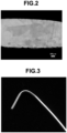
- Fig. 2 shows an example (scanning electron microscope photograph) of the observation results.
- Fig. 2 shows a section parallel to the longitudinal direction of the manufactured wire. That is, a section of the manufactured sample was processed by dry etching (ion milling) using argon gas, and the obtained sample was observed by a scanning electron microscope.
- Comparative samples will be explained below.
- the compositions of the comparative samples were the same as those of Samples 1 to 10 in Table 1.
- Fig. 3 shows the state of Sample 4 after the bending test. As shown in Fig. 3 , the wire of Example 1 was bent without breaking, and gloss remained on the surface.
- thermomechanical treatment of a wire and a plate made of ruthenium or a ruthenium alloy will be explained below.
- grain boundary oxidation caused by a decrease in oxidation resistance and grain boundary cracking during the processing caused by the grain boundary oxidation are problems.
- coarse crystal grains are obtained through shape-controlled solidification by near net shape in advance. This makes it possible to obtain a final target shape while suppressing a decrease in yield caused by grain boundary cracking occurring in the thermomechanical treatment.
- crystal grains can be micronized during the processing in a portion influenced by the processing, but these crystal grains can be coarsened to a certain degree by the annealing. Accordingly, a product obtained by the thermomechanical treatment from the wire manufactured by the wire manufacturing method using the apparatus shown in Figs. 1A and 1B explained in Example 1 has a portion where the number of crystal grains is 120 or more per 1 mm 2 . This applies not only to a wire but also to a plate.
- a metal member is composed of polycrystals of a metal made of ruthenium or an alloy containing ruthenium at a maximum ratio, the aspect ratio of the crystal grain is 1.5 or more, a plurality of crystal grains are arranged with their major axes being pointed in the same direction, and the number of crystal grains in a section in the direction of the major axes of the crystal grains is 120 or less per 1 mm 2 . Consequently, the first embodiment can provide a material (metal member) having performance equal to or higher than those of platinum, iridium, and an iridium alloy, and less expensive than these metals. For example, the present invention can provide a metal member that has performance equal to or higher than those of platinum, iridium, and an iridium alloy, and is about ten times less expensive than these metals.
- the metal member preferably contains 2 (inclusive) to 80 (inclusive) crystal grains per 1 mm 2 , and preferably has a Vickers Hardness of less than 350 Hv.
- thermocouple is a component using a wire.
- a thermocouple using ruthenium as an electrode was reported in the past.
- this thermocouple is presently not widely spread because the processability of ruthenium is very low, so an expensive iridium thermocouple is used.
- a high-temperature structure such as a crucible containing ruthenium as a main alloy element is not widely spread, and iridium is used instead. Therefore, if iridium can be replaced with ruthenium, it is greatly expected that price reduction and widespread use advance.
- a metal member of the second embodiment is composed of a metal made of an alloy containing ruthenium at a maximum ratio.
- This metal can be either monocrystalline or polycrystalline.
- the crystal grains of the metal member have an aspect ratio of 1.2 or more. In other words, the length of the major axis of the crystal grain is 1.2 times or more the length of its minor axis.
- This metal member is flame-retardant.
- the ruthenium alloy forming the metal member of the second embodiment has a composition represented by chemical formula Ru ⁇ M1 ⁇ M2 ⁇ M3 ⁇ M4 ⁇ .
- M1 is one of Rh, Pd, Os, and Pt
- M2 is one of Ta, W, Mo, Nb
- M3 is one of Cr, Mn, Fe, Co, Ni, and V
- M4 is one of Ti, Zr, Hf, Al, and Sc.
- Rh, Pd, Os, Ir, and Pt increase the processability by dissolving in Ru by solid solution.
- Ta, W, Mo, Nb, and Re increase the processability and the volume resistivity by dissolving in Ru by solid solution.
- Cr, Mn, Fe, Co, Ni, and V increase the processability and the volume resistivity by dissolving in Ru by solid solution.
- Ti, Zr, Hf, Al, and Sc improve the processability by combining with elements such as O and P that reduce the processability.
- a plurality of crystal grains forming a polycrystalline metal member are arranged with their major axes being pointed in the same direction, and the number of crystal grains in a section parallel to the major axis direction of the crystal grains is 2 (inclusive) to 260 (inclusive) per 0.1 mm 2 .
- the number of crystal grains is more preferably 55 or less per 0.1 mm 2 , and further preferably 20 or less per 0.1 mm 2 .
- the metal member is, e.g., a wire, and the extending direction of the wire is the major axis direction of the crystal grains.
- the crystal grains of the metal member are, e.g., columnar crystals, and the material structure is preferably obtained such that the columnar crystals form a bundle in an arbitrary section.
- the amount of equiaxed crystals is preferably small in the material structure.
- the ratio of equiaxed crystals is limited in order to suppress a decrease in mechanical strength caused by an increase in grain boundary area. Note that there is no limit on the number of crystal grains in the minor axis direction of the crystal grains.
- the grain boundary area is regulated by defining the number of crystal grains in a section parallel to the major axis direction of the crystal grains, in the second embodiment as well.
- the grain boundary of a metal member containing ruthenium is the starting point of high-temperature deterioration or damage, so the grain boundary area is regulated in order to limit this.
- a wire manufactured by a powder metallurgy method necessarily has many crystal grains and many air gaps.
- a wire made of the metal member according to the second embodiment has an oxidation resistance higher than that of a wire manufactured by the powder metallurgy method and having the same composition.
- the Vickers hardness of the metal member of the second embodiment is 160 Hv (inclusive) to 400 Hv (exclusive).
- This definition of the hardness is related to the residual strain in the metal member.
- the processing strain acts as the driving force of recrystallization when the wire is heated to a recrystallization temperature or higher, and changes the material structure (a recrystallized structure).
- the recrystallized structure increases the grain boundary area, and this accelerates high-temperature wastage and breaking.
- ruthenium alloy wire for which the use temperature is presumably equal to or higher than the recrystallization temperature, it is favorable to reduce the residual strain in order to suppress a structural change at a high temperature, in addition to limiting the number of crystal grains in the initial state (before the use in a high-temperature atmosphere).
- a wire (metal member) having a Vickers hardness of 400 Hv or more is in a state in which the residual strain is excessive.
- recrystallization increases the grain boundary area, and this may increase the oxidation waste amount.
- the metal member softens due to recrystallization, and a combination of the decreases in hardness and strength and the increase in grain boundary area increases the possibility that breaking occurs from the grain boundary as a starting point.
- it is originally unpreferable to use a ruthenium alloy wire having a Vickers hardness of less than 160 Hv in the second embodiment because it does not have strength required at room temperature.
- a wire in the second embodiment means a thin-wire-like metal member having a diameter of 0.1 mm (inclusive) to 3.0 mm (inclusive), as in the first embodiment.
- the diameter is desirably 0.2 mm (inclusive) to 0.8 mmm (inclusive) for a thermocouple, and 0.3 mm (inclusive) to 0.8 mm (inclusive) for a spark plug electrode.
- a plate means a metal member having at least two linear regions in a section perpendicular to the longitudinal direction.
- the metal member of the second embodiment is formed such that the number of crystal grains at room temperature is limited and a structural fluctuation by recrystallization hardly occurs even when the metal member is heated to a high temperature, as in the first embodiment.
- the number of crystal grains varies little when the metal member is heated to a recrystallization temperature (the recrystallization temperature is 1,200°C to 1,500°C although it varies due to the composition of the metal member) or higher.
- a change in hardness is reduced. More specifically, when the heating conditions are a heating temperature of 1,200°C and a heating time of 20 hours, a hardness change rate "100 [%] - (hardness after heating/hardness before heating)" is 15% or less.
- tungsten, tantalum, molybdenum, or the like having a high melting point and a low vapor pressure has been used as a metal member to be used as a resistance heating element.
- tungsten, tantalum, and molybdenum are extremely difficult to process at room temperature.
- even a resistance heating element is required to be processable into a complicated shape, in order to achieve a more efficient furnace temperature distribution. Accordingly, a demand has arisen for a metal member having processability at higher room temperature.
- the present invention can provide a metal member having performance equal to or higher than those of tungsten, tantalum, and molybdenum, and processability higher than those of these metals.
- the metal member of the second embodiment described above will be explained.
- the explanation will be made by taking, as an example, a method of manufacturing a wire as a metal member.
- the limitation on the number of crystal grains and the limitation on the hardness for reducing the residual strain are necessary in the second embodiment as well.
- the ⁇ -PD method is applied as a wire manufacturing process capable of achieving both the limitation on the number of crystal grains and the suppression of the residual strain.
- a wire of the second embodiment can also be manufactured based on single crystal manufacturing processes, such as a FZ (Floating Zone) method and a zone melting method, other than the ⁇ -PD method.
- single crystal manufacturing processes such as a FZ (Floating Zone) method and a zone melting method, other than the ⁇ -PD method.
- FZ Floating Zone
- zone melting method other than the ⁇ -PD method.
- these single crystal growing methods are more suitable than the ⁇ -PD method.
- the FZ (Floating Zone) method and the zone melting method cannot manufacture a continuous wire of ⁇ 3 mm or less by near net shape.
- processing when manufacturing a wire having a small diameter of 3 mm or less as a final product by using the FZ method or the like, processing must be performed a plurality of times after the FZ method. When processing is performed a plurality of times, the strain is very likely to remain, and the hardness after the processing becomes Hv 400 or more. Also, if this processed wire is adjusted to less than Hv 400 by annealing or the like, a recrystallized structure containing equiaxed crystals is formed. This extremely deteriorates the mechanical characteristics, particularly the toughness.
- a wire made of a ruthenium alloy was manufactured based on the ⁇ -PD method by using the manufacturing apparatus explained with reference to Figs. 1A and 1B .
- a ruthenium wire was also manufactured.
- the growth crystal 104 is brought into contact with the molten metal 103 in the crucible 102 via the nozzle 106 of the bottom 107.
- the wire 105 is obtained by pulling down (moving) the growth crystal 104 (downward) at a predetermined rate.
- Ruthenium and a ruthenium alloy prepared in advance were placed in the crucible 102 made of zirconia (the vessel dimensions were 40 ⁇ 30 ⁇ 50), in the manufacture of samples of Example 2 as well.
- Example 2 shows the compositions of these samples. Table 2 also shows the results of experiments in Example 2.
- the number of crystal grains and the hardness were first measured by observing the structure of the metal member.
- the manufactured wire was cut into a length of 1 mm, and the cut wire was further cut in half in the longitudinal direction. Microscopic observation was performed on each sample manufactured as described above, and the number of crystal grains was measured by setting an arbitrary observation field having an area of 0.1 mm 2 .
- a section of the manufactured sample was processed by dry etching (ion milling) using argon gas, and the obtained sample was observed by a scanning electron microscope.
- Comparative samples will be explained below.
- the compositions of the comparative samples were the same as those of Samples 11 to 25 in Table 2.
- thermomechanical treatment of a wire and a plate made of a ruthenium alloy will be explained below.
- grain boundary oxidation caused by a decrease in oxidation resistance and grain boundary cracking during the processing caused by the grain boundary oxidation are problems.
- coarse crystal grains are obtained through shape-controlled solidification by near net shape in advance. This makes it possible to obtain a final target shape while suppressing a decrease in yield caused by grain boundary cracking occurring in the thermomechanical treatment.
- crystal grains can be micronized during the processing in a portion influenced by the processing, but these crystal grains can be coarsened to a certain degree by the annealing. Accordingly, a product obtained by the thermomechanical treatment from the wire of Example 2 has a portion where the number of crystal grains is 260 or more per 0.1 mm 2 . This applies not only to a wire but also to a plate.
- a metal member is composed of a metal made of an alloy containing ruthenium at a maximum ratio.
- this metal alloy containing ruthenium at a maximum ratio.
- the aspect ratio of the crystal grain is 1.2 or more, a plurality of crystal grains are arranged with their major axes being pointed in the same direction, and the number of crystal grains in a section in the direction of the major axes of the crystal grains is 260 or less per 0.1 mm 2 .
- the second embodiment can also provide a material (metal member) having performance equal to or higher than those of platinum, iridium, and an iridium alloy, and less expensive than these metals.
- the present invention can provide a metal member that has performance equal to or higher than those of platinum, iridium, and an iridium alloy, and is about ten times less expensive than these metals.
- the metal member of the second embodiment preferably contains 55 or less crystal grains per 0.1 mm 2 , and preferably has a Vickers Hardness of less than 350 Hv. More preferably, the metal member contains 20 or less crystal grains per 0.1 mm 2 , and has a Vickers hardness of less than 300 Hv.
- a resistance heating element is a component using a wire. Ruthenium is conventionally not applied because the processability is extremely low.
- the present invention can provide a high-temperature heating element that is less expensive than platinum and has processability higher than that of tungsten or the like.
- a metal member manufactured by the present invention contains crystal grains larger than those obtained by the conventional methods. This increases the creep strength at a high temperature, and also contributes to prolonging the life of the member.
- an alloy wire when using an alloy wire as a spark plug, the wire must be cut into a chip having a thickness of about 1 mm. Shearing is most widely used when cutting a wire into a spark plug, and an existing alloy having high ductility desirably has a structure containing fine crystal grains in order to prevent shear droop during cutting.
- an existing alloy having high ductility desirably has a structure containing fine crystal grains in order to prevent shear droop during cutting.
- ruthenium and a ruthenium alloy are inferior in ductility to an iridium alloy and a platinum alloy, and hence have the advantage that shear droop hardly occurs during shearing even in a structure containing coarse crystal grains close to a single crystal. Accordingly, processing can be performed without decreasing the oxidation resistance.
- the present invention has high novelty and inventive step in that while expensive iridium is replaced with inexpensive ruthenium, the high-temperature oxidation resistance is improved by reducing grain boundaries by increasing the grain size, and a thermomechanical treatment from near net shape is implemented by improving the ductility.
- a metal a ruthenium alloy mainly containing ruthenium has a high-temperature resistance and an oxidation resistance equal to those of iridium and an iridium alloy, and it is found that a damage mode in this high-temperature atmosphere often starts from the grain boundary. That is, a metal mainly containing ruthenium preferentially oxidizes (corrodes) in the grain boundaries and wastes in a high-temperature atmosphere. In addition, the metal tends to break from the grain boundaries because a decrease in strength is large in the grain boundaries.
- a grain boundary preferential deteriorating mechanism like this is well known for iridium (see patent literature 1).
- deterioration of the grain boundaries is suppressed by improving the orientation based on the opinion that preferential deterioration of the grain boundaries extends due to the orientation difference between adjacent crystals.
- regulating the area of the grain boundaries as the original cause of deterioration is a measure that is more essential and most effective.
- the oxidation resistance is successfully improved by regulating the area of the grain boundaries in iridium.
- a similar damage mode is expected in ruthenium as well. Accordingly, it is presumably possible to suppress oxidation (corrosion) in the grain boundaries if the area of the grain boundaries can be regulated in ruthenium.
- patent literature 1 the structure (orientation) of an iridium wire immediately after the manufacture is defined, but whether the material structure is maintained when exposed to a high temperature is not clarified.
- patent literatures 2 and 3 the effect of improving the oxidation resistance is increased by regulating the area of the grain boundaries of iridium.
- patent literature 4 discloses a method of forming a clad structure with a highly ductile alloy and repeating hot processing and a heating step a plurality of times.
- a material structure obtained by hot processing like this is fibrous and unavoidably has many grain boundaries.
- the present inventors have developed a technique of reducing the grain boundaries by increasing the grain size of ruthenium, for reference and not part of the invention, and a ruthenium alloy, and have shown for the first time in the world by taking examples that regulating the area of the grain boundaries is also effective to suppress deterioration (corrosion) of ruthenium and a ruthenium alloy.
- the present inventors have found that in order to improve the durability of a ruthenium wire in a high-temperature atmosphere, it is important that the grain boundary area is small, and this small grain boundary area is maintained not only when the wire is manufactured (at room temperature) but also when the wire is exposed to a high temperature, i.e., it is important that a structural change hardly occurs due to heating.
- the present inventors have made extensive studies including drastic reexamination of the manufacturing method, and have found a suitable ruthenium wire.
- the present invention regulates the grain boundary area by defining the number of crystal grains in an arbitrary region in a longitudinal-direction section.
- the grain boundary of a metal member containing ruthenium is the starting point of a high-temperature deterioration damage, and the grain boundary area is regulated in order to restrict this.
- a wire simply manufactured by a powder metallurgy method necessarily has many crystal grains and many air gaps. Accordingly, a wire of the present invention has an oxidation resistance higher than that of a wire manufactured by the powder metallurgy method and having the same composition.
- the definition of the hardness is related to the residual strain in the metal member.
- the processing strain acts as the driving force of recrystallization when the wire is heated to a recrystallization temperature or higher, and changes the material structure (a recrystallized structure).
- the recrystallized structure increases the grain boundary area, and this accelerates high-temperature wastage and breaking.
Description
- The present invention relates to a metal member made of ruthenium or a ruthenium alloy.
- Chemically stable refractory platinum-group elements are used as metal members to be used as electrodes (a central electrode and a ground electrode) of a spark plug, as various sensor electrodes, and in temperature measurement, at high temperatures. Conventionally, platinum and a platinum alloy are used because they have high plastic deformability.
- On the other hand, as the processing techniques have advanced in recent years, a metal member (to be sometimes referred to as an iridium wire hereinafter) made of iridium or an iridium alloy having a melting point higher than that of platinum is also beginning to be used as a spark plug electrode.
- The spark plug electrode is exposed to a high-temperature oxidizing environment in a combustion chamber, so there is a concern about wastage by high-temperature oxidation. Therefore, the spark plug electrode is required to have a high melting point and a high oxidation resistance. Conventionally, a general method of improving the durability of an iridium wire is to properly alloy an additive element such as rhodium, platinum, or nickel in order to adjust the material composition. However, when performing only the improvement based on composition adjustment by alloying, other characteristics deteriorate. This makes it necessary to improve the high-temperature oxidation resistance by a method other than composition adjustment.
- As a technique of improving the high-temperature characteristics, approaches based on adjustment of the material structure have also been attempted in addition to adjustment of the composition (constituent elements). For example, patent literature 1 discloses a metal member made of iridium or an iridium alloy in which the abundance ratio of crystals having <100> orientation that appears as preferred orientation during processing is intentionally increased by focusing attention on the orientation of metal crystals.
- This improvement of the high-temperature characteristics of a metal member performed by controlling the material structure is not regarded as being completed. For example, when iridium wires disclosed in patent literatures 2 and 3 are compared with iridium wires manufactured by the conventional wire processing, a reduction in oxidation waste amount is observed in a high-temperature oxidizing atmosphere, i.e., a certain effect is confirmed. Since, however, demands have arisen for further improving the high-temperature characteristics, an iridium wire having better high-temperature characteristics is being required. Patent Literature 5 discloses Ru based alloy for spark plug electrodes.
- For the spark plug electrode, for example, it is required to prolong the durability life and further improve the durability in accordance with the improvement in engine performance. Similar high-temperature oxidation resistance improvements are required for thermocouple applications as well. In addition, an area as a target of temperature measurement is sometimes installed in a secluded place. Accordingly, it is also important that a metal member is easy to bend, i.e., has so-called ductility.
-
- Patent Literature 1:
Japanese Patent Laid-Open No. 2012-136733 - Patent Literature 2:
Japanese Patent Laid-Open No. 2015-190012 - Patent Literature 3: International Publication No.
2012/090714 - Patent Literature 4:
U.S.P. No. 8,979,696 Patent Literature 5:U.S. patent application No. 2011/127900 - Since platinum and iridium are very expensive, wires and their processed products using platinum and iridium are also expensive, and this is preventing the widespread use of these metal members. At present, therefore, it is required to obtain a metal member having performance equal to or higher than those of platinum, iridium, and an iridium alloy by using low-cost materials.
- The present invention has been made to solve the problems as described above, and has as its object to provide a metal member that has performance equal to or higher than those of platinum, iridium, and an iridium alloy and is less expensive than these metals. Means of Solution to the Problem
- A metal member according to the present invention is defined in the claims.
- A metal member according to the present invention is composed of a metal made of an alloy containing Ru at a maximum ratio, wherein a composition is represented by RuαM1βM2γM3δM4ε, M1 is one of Rh, Pd, Os, Ir, and Pt, M2 is one of Ta, W, Mo, Nb, and Re, M3 is one of Cr, Mn, Fe, Co, Ni, and V, M4 is one of Ti, Zr, Hf, Al, and Sc, and 0.5 < α < 1, 0 ≤ β ≤ 0.5, 0 ≤ γ ≤ 0.5, 0 ≤ δ ≤ 0.5, 0 ≤ ε ≤ 0.1, and 0 < β + γ + δ + ε < 0.5.
- In the above metal member, an aspect ratio of a crystal grain of the metal that is made polycrystalline is 1.2 or more, a plurality of crystal grains are arranged with major axes thereof being pointed in the same direction, and the number of crystal grains in a section in the direction of the major axes of the crystal grains is 260 or less per 0.1 mm2. Also, the metal has a Vickers hardness of 160 Hv (inclusive) to 400 Hv (exclusive).
- As explained above, the present invention has the excellent effect that it is possible to provide a metal member that has performance equal to or higher than those of platinum, iridium, and an iridium alloy and is less expensive than these metals.
-
-
Fig. 1A is a view showing the arrangement of a manufacturing apparatus used to form samples of a metal member according to Example 1 of the present invention; -
Fig. 1B is a view showing the arrangement of a part of the manufacturing apparatus used to form the samples of the metal member according to Example 1 of the present invention; -
Fig. 2 is a photograph showing the result of observation performed by a scanning electron microscope on the section of a sample of a metal member formed in Example 1 of the present invention; and -
Fig. 3 is a photograph showing the outer experience of a bending test conducted on a metal member formed in Example 1 of the present invention. - Embodiments of the present invention will be explained below with reference to the accompanying drawings.
- The first embodiment of the present invention will be explained below. A metal member according to the first embodiment of the present invention is composed of polycrystals of a metal made of Ru (ruthenium) or an alloy containing ruthenium at a maximum ratio. Also, the aspect ratio of the crystal grains of the polycrystalline metal member is 1.5 or more. In other words, the length of the major axis of the crystal grain is 1.5 times or more the length of its short axis. The metal member according to the present invention is flame-retardant.
- Note that the ruthenium alloy that is not part of the present invention is represented by chemical formula KuαM1βM2γM3ζ where M1 is Rh, Pd, Os, Ir, or Pt, M2 is Ta, W, or Re, and M3 is an element that improves the corrosion resistance by forming a stable compound with ruthenium, or an element that improves the corrosion resistance by dissolving in ruthenium by solid solution. In this chemical formula, 0.5 ≤ α ≤ 1, 0 ≤ β ≤ 0.5, 0 ≤ γ ≤ 0.5, 0 < ζ < 0.5, and 0 ≤ β + γ + ζ ≤ 0.5. Note that the stable compound is a compound that stably exists at room temperature. For example, a compound having a melting point of 1,400°C or more is favorable as the metal member of the first embodiment.
- A plurality of crystal grains forming the metal member are arranged with their major axes being pointed in the same direction, and the number of crystal grains in a section parallel to the direction of the major axes of the crystal grains is 2 (inclusive) to 120 (inclusive) per 1 mm2. This metal member is, e.g., a wire, and the extending direction of the wire is the major axis direction of the crystal grains. The crystal grains of the metal member are, e.g., columnar crystals, and the material structure is preferably such that the columnar crystals form a bundle in an arbitrary section. Also, the amount of equiaxed crystals is preferably small in the material structure. The ratio of equiaxed crystals is limited in order to suppress a decrease in mechanical strength caused by an increase in grain boundary area. Note that there is no limit on the number of crystal grains in the short-axis direction of the crystal grains.
- In the present invention as described above, the grain boundary area is regulated by defining the number of crystal grains in a section parallel to the major axis direction of the crystal grains. The grain boundary of a metal member containing ruthenium is the starting point of high-temperature deterioration or damage, so the grain boundary area is regulated in order to limit this. For example, a wire manufactured by a powder metallurgy method necessarily has many crystal grains and many air gaps. Accordingly, a wire made of the metal member according to the present invention has an oxidation resistance higher than that of a wire manufactured by the powder metallurgy method and having the same composition.
- It is also important that the Vickers hardness of the metal member of the first embodiment is 200 Hv (inclusive) to 400 Hv (exclusive). This definition of the hardness is related to the residual strain in the metal member. For example, in the manufacture of a ruthenium wire and a ruthenium alloy wire manufactured by combining processing (hot processing and cold processing) and annealing of an ingot obtained by melting and casting, introduction and relaxation (removal) of processing strain alternately occur, and a metal member processed at a high processing rate until it becomes a wire contains a corresponding residual strain. The processing strain acts as the driving force of recrystallization when the wire is heated to a recrystallization temperature or higher, and changes the material structure (a recrystallized structure). The recrystallized structure increases the grain boundary area, and this accelerates high-temperature wastage and breaking.
- Accordingly, for a ruthenium wire and a ruthenium alloy wire for which the use temperature is presumably equal to or higher than the recrystallization temperature, it is favorable to reduce the residual strain in order to suppress a structural change at a high temperature, in addition to limiting the number of crystal grains in the initial state (before the use in a high-temperature atmosphere).
- According to the examination by the present inventors, a wire (metal member) having a Vickers hardness of 400 Hv or more is in a state in which the residual strain is excessive. When exposed to a high temperature equal to or higher than the recrystallization temperature, therefore, recrystallization increases the grain boundary area, and this may increase the oxidation waste amount. In addition, the metal member softens due to recrystallization, and a combination of the decreases in hardness and strength and the increase in grain boundary area increases the possibility that breaking occurs from the grain boundary as a starting point. On the other hand, it is originally unpreferable to use a ruthenium wire and a ruthenium alloy wire having a Vickers hardness of less than 200 Hv because they do not have strength required at room temperature.
- Note that in order to obtain a wire having a limited hardness as described above, it is necessary to perform processing so that a necessary wire diameter is obtained, while limiting the processing conditions so that no strain remains. This manufacturing process will be described later. Note also that "a wire" in the first embodiment means a thin-wire-like metal member having a diameter of 0.1 mm (inclusive) to 3.0 mm (inclusive). In particular, the diameter is desirably 0.2 mm (inclusive) to 0.8 mmm (inclusive) for a thermocouple, and 0.3 mm (inclusive) to 0.8 mm (inclusive) for a spark plug electrode. Furthermore, "a plate" means a metal member having at least two linear regions in a section perpendicular to the longitudinal direction.
- As described above, the metal member of the first embodiment is formed such that the number of crystal grains at room temperature is limited and a structural fluctuation by recrystallization hardly occurs even when the metal member is heated to a high temperature. In the metal member of the first embodiment, therefore, the number of crystal grains varies little when the metal member is heated to a recrystallization temperature (the recrystallization temperature is 1,200°C to 1,500°C although it varies due to the composition of the metal member) or higher. In addition, a change in hardness is reduced. More specifically, when the heating conditions are a heating temperature of 1,200°C and a heating time of 20 hours, a hardness change rate "100 [%] - (hardness after heating/hardness before heating)" is 15% or less.
- Next, a method of manufacturing the above-described metal member will be explained. The explanation will be made by taking, as an example, a method of manufacturing a wire as a metal member. A wire of the first embodiment requires the limitation on the number of crystal grains and the limitation on the hardness in order to reduce the residual strain. It is not easy to achieve these limitations by the conventional wire manufacturing process. In the conventional wire manufacturing process, an ingot obtained by the powder metallurgy method or melting and casting is formed into a thin line by performing a rolling process (grooved roll rolling process), a drawing process, and the like. In these manufacturing steps, the number of crystal grains cannot be controlled.
- Also, during the course of forming a wire from an ingot, the residual strain exists because processing is performed at a very high processing rate. The residual strain can be reduced by performing hot processing. However, a large amount of residual strain exists because the processing is repetitively performed.
- On the other hand, as a wire manufacturing process that can achieve both the limitation on the number of crystal grains and the suppression of the residual strain, it is possible to apply a micro-pulling-down method (to be referred to as a µ-PD method hereinafter) as one mode of the single crystal manufacturing process (see patent literature 2). In the µ-PD method, the number of crystal grains in a section in the major axis direction of the crystal grains can be decreased to a small number of about 260 per 0.1 mm2. In addition, the µ-PD method can control the number of crystal grains by using, e.g., a pulling-down rate.
- In the µ-PD method as shown in
Figs. 1A and 1B , amolten metal 103 as a material is placed in acrucible 102 that can be heated by aradiofrequency induction coil 101, and crystal growth is performed by pulling down a solidified metal (wire) 105 through anozzle 106 via agrowth crystal 104. Thenozzle 106 is formed in abottom 107 of thecrucible 102. Thecrucible 102 is supported and fixed on a crucible table 109 inside aprocessing chamber 108. Note thatFig. 1B shows a dotted-line circle inFig. 1A in an enlarged scale. - The µ-PD method is suitably applied to the manufacture of a ruthenium wire and a ruthenium alloy wire because the µ-PD method can manufacture a quasi-monocrystalline metal member having a small number of crystal grains while controlling the shape of crystal grains. Also, the µ-PD method grows crystals while restricting the sectional area to a very small area by the
nozzle 106. Therefore, a wire manufactured by this method has a small wire diameter and requires no processing thereafter, or a wire and a plate having desired dimensions can be obtained by a small number of processes. Accordingly, crystals grown by the µ-PD method have little strain and hence require no additional processing. This makes it possible to largely reduce the residual strain, and obtain a low-hardness wire or plate required by the present invention. Thus, manufacturing a metal member such as a wire by using the µ-PD method is an efficient method capable of manufacturing a target metal member by near net shape. - The wire manufacturing method based on the µ-PD method handles a refractory material such as ruthenium or its alloy. Therefore, it is important that the constituent material of the
crucible 102 is a material that hardly dissolves nor volatilizes at a high temperature. More specifically, it is possible to use ceramics such as magnesia, zirconia, and alumina, and carbon (graphite). Thenozzle 106 formed in thebottom 107 of thecrucible 102 has both a function of cooling and solidifying the molten metal that passes through themolten metal 103 from the bottom 107, and a function of restricting and shaping the metal (wire) 105 being solidified as a jig (die). Like thecrucible 102, the material of thenozzle 106 is also preferably a material that hardly dissolves nor volatilizes at a high temperature. The inner wall of thenozzle 106 preferably has a smooth surface because friction occurs between the inner wall and the solidified metal. - An important factor when manufacturing a wire having a limited number of crystal grains by the µ-PD method is the position (level) of a solid-
liquid interface 111 between themolten metal 103 and the solidified metal (wire) 105. The position of the solid-liquid interface 111 is preferably near the center of thenozzle 106 in the vertical direction. If the position of the solid-liquid interface 111 is on the upper side (the side of the crucible 102), the moving distance of the solidified metal (wire) 105 increases, and the pulling-down resistance increases accordingly. Consequently, abrasion and damage of thenozzle 106 occur, and this makes it difficult to control the shape and dimensions of the wire. On the other hand, if the solid-liquid interface 111 is on the lower side (the exit side of the nozzle 106), themolten metal 103 is discharged from thenozzle 106, and the diameter of the wire may increase. The position of the slid-liquid interface 111 is controlled by properly adjusting the length (thickness) and the pulling-down rate of thenozzle 106. When manufacturing a wire having a wire diameter expected as the metal member of the first embodiment, the length (thickness) of thenozzle 106 is preferably 3 to 30 mm, and the corresponding pulling-down rate is preferably 0.5 to 200 mm/min. - When manufacturing a wire by the µ-PD method, it is also necessary to adjust the cooling rate of the
wire 105 discharged from thenozzle 106. Thewire 105 discharged from thenozzle 106 is in a solid-phase region, but may form microcrystals (equiaxed crystals) if rapidly cooled. Accordingly, thewire 105 discharged from thenozzle 106 is preferably slowly cooled at a low cooling rate until the temperature becomes lower than the recrystallization temperature. More specifically, the cooling rate is preferably 120°C/sec to 1°C/sec until the temperature of thewire 105 becomes at least 1,200°C or less. - Note that cooling can also be performed at the low cooling rate described above even in a temperature region in which the wire temperature is 1,200°C or less, but the cooling rate can be made higher than the abovementioned rate by taking account of the manufacturing efficiency when the wire temperature is 1,000°C or less. Also, the cooling rate is sometimes adjusted by using the heat of the crucible 102 (the molten metal 103) by, e.g., connecting an after heater made of a heat-conductive material such as ceramics to the lower portion of the
crucible 102. The processing of themolten metal 103 in thecrucible 102 and the pulling down of thewire 105 are preferably performed in an atmosphere of an inert gas (e.g., nitrogen, argon, or helium) in order to prevent oxidation. - The wire diameters of a ruthenium wire and a ruthenium alloy wire manufactured by the µ-PD method may also be adjusted by additional processing. In this case, however, it is necessary to pay attention to the processing temperature and the processing rate in order to prevent the residual strain. More specifically, it is necessary to set the processing temperature at 1,500°C or more, and set the processing rate at less than 12% for one processing (one pass). If the processing temperature is low or the processing rate is high, strain remains, and the structural changes due to recrystallization occur when the wire is used at a high temperature. A ruthenium wire of the first embodiment manufactured by the µ-PD method explained above can be used as it is properly cut in accordance with an application.
- Note that a ruthenium wire of the first embodiment can also be manufactured based on single crystal manufacturing processes, such as a FZ (Floating Zone) method and a zone melting method, other than the µ-PD method. When manufacturing a single crystal having a relatively large diameter, these single crystal growing methods are more suitable than the µ-PD method. However, the FZ (Floating Zone) method and the zone melting method cannot manufacture a continuous wire of φ3 mm or less by near net shape.
- Furthermore, when manufacturing a wire having a small diameter of 3 mm or less as a final product by using the FZ method or the like, processing must be performed a plurality of times after the FZ method. When processing is performed a plurality of times, the strain is very likely to remain, and the hardness after the processing becomes Hv 400 or more. Also, if this processed wire is adjusted to less than Hv 400 by annealing or the like, a recrystallized structure containing equiaxed crystals is formed. This extremely deteriorates the mechanical characteristics, particularly the toughness.
- The present invention will be explained in more detail below by using the results of actually conducted experiments.
- First, samples of the metal member of the first embodiment of the present invention will be explained. A wire made of ruthenium or a ruthenium alloy was manufactured based on the µ-PD method by using the manufacturing apparatus explained with reference to
Figs. 1A and 1B . When manufacturing a wire by the µ-PD method, thegrowth crystal 104 is brought into contact with themolten metal 103 in thecrucible 102 via thenozzle 106 of the bottom 107. After that, thewire 105 is obtained by pulling down (moving) the growth crystal 104 (downward) at a predetermined rate. - In the manufacture of samples of Example 1, ruthenium and a ruthenium alloy (each of which had a purity of 99% or more) prepared in advance were placed in the
crucible 102 made of zirconia (the vessel dimensions were 40 × 30 × 50). In addition, the growth crystal 104 (a φ0.8-mm seed crystal) was inserted from below the nozzle 106 (dimensions: inner diameter = 1mm, length = 5 mm) formed in thebottom 107 of thecrucible 102. In this state, the material was melted by radiofrequency induction heating by using theradiofrequency induction coil 101. - After the
molten metal 103 of the material was formed in thecrucible 102, pulling down was performed at a pulling-down rate of 5 mm/min. In this pulling down, argon gas (1 L/min) was made to flow from the upper portion to the lower portion of thecrucible 102. In this example, in a zone of 30 mm from the exit of thenozzle 106, the cooling rate was set at 50°C/sec, and slow cooling was performed until the temperature of thewire 105 became 1,200°C or less. By the manufacturing method described above, thewire 105 having a wire diameter of 0.8 mm and a length of 150 mm was manufactured. Samples 1 to 10 were manufactured as Example 1. Table 1 below shows the compositions of these samples. Table 1 also shows the results of experiments. - In the experiments, the number of crystal grains and the hardness were first measured by observing the structure of the metal member. In these measurements, the manufactured wire was cut into a length of 1 mm, and the cut wire was further cut in half in the longitudinal direction. Microscopic observation was performed on each sample manufactured as described above, and the number of crystal grains was measured by setting an arbitrary observation field having an area of 0.25 mm2.
Fig. 2 shows an example (scanning electron microscope photograph) of the observation results.Fig. 2 shows a section parallel to the longitudinal direction of the manufactured wire. That is, a section of the manufactured sample was processed by dry etching (ion milling) using argon gas, and the obtained sample was observed by a scanning electron microscope. - Also, the presence/absence and the number of equiaxed crystals having an aspect ratio of 1.2 or more were measured. In addition, the Vickers hardness of each sample was measured by a Vickers hardness meter. The results of the observation revealed that in each of Samples 1 to 10, the number of crystal grains in the longitudinal-direction section fell within a predetermined range, and the hardness was relatively low.
[Table 1] Sample 1 is for reference only. Composition Number of crystal grains Hardness [Hv] Ru Rh Pt Re Ni Al Before heating Before heating 1500 °C Sample 1 100 - - - - - 21 243 226 Sample 2 94 5 - 1 - - 29 254 232 Sample 3 80 10 10 - - - 24 271 250 Sample 4 80 20 - - - - 43 293 268 Sample 5 89 10 - 1 - - 68 231 219 Sample 6 80 - 20 - - - 55 313 276 Sample 7 89 5 5 1 - - 83 301 273 Sample 8 94 2.5 2.5 1 - - 78 340 315 Sample 9 95 - - - 5 - 29 249 230 Sample 10 87 10 - - - 3 24 244 229 - Comparative samples will be explained below. The compositions of the comparative samples were the same as those of Samples 1 to 10 in Table 1. Each comparative sample was obtained by manufacturing an ingot (diameter = 12 mm) made of ruthenium and a ruthenium alloy by arc melting, and processing the ingot into a wire through hot processing and heating. In this processing step, the processing was repetitively performed until target dimensions were obtained in each of hot forging, hot wire drawing, and hot swaging. This repetition of hot wire drawing on the comparative samples was performed in order to give the wire a high orientation. However, it was impossible to manufacture the comparative samples because they broke before φ0.8 mm was reached.
- Then, high-temperature oxidation heating was performed on each sample, and a structural change and a hardness change after the heating were examined. In addition, a high-temperature oxidation resistance was evaluated by measuring an oxidation waste amount after the heating. Furthermore, the presence/absence of breakage of each sample was evaluated by conducting a bending test on the heated wire. In this bending test, the evaluation was performed by checking breaking of the wire and cracking of the surface when the wire was bent through 90°.
- Sufficient high-temperature oxidation resistances were obtained by the wires of Samples 1 to 10. Changes in number of crystal grains before and after the heating were small, and hardness changes were also suppressed. In addition, neither breaking nor surface cracking was found in each sample in the bending test after the heating.
Fig. 3 shows the state of Sample 4 after the bending test. As shown inFig. 3 , the wire of Example 1 was bent without breaking, and gloss remained on the surface. - A thermomechanical treatment of a wire and a plate made of ruthenium or a ruthenium alloy will be explained below. In the conventional manufacturing method of performing a thermomechanical treatment on an ingot, grain boundary oxidation caused by a decrease in oxidation resistance and grain boundary cracking during the processing caused by the grain boundary oxidation are problems. By contrast, in the wire manufacturing method using the apparatus shown in
Figs. 1A and 1B explained in Example 1, coarse crystal grains are obtained through shape-controlled solidification by near net shape in advance. This makes it possible to obtain a final target shape while suppressing a decrease in yield caused by grain boundary cracking occurring in the thermomechanical treatment. - In this method, crystal grains can be micronized during the processing in a portion influenced by the processing, but these crystal grains can be coarsened to a certain degree by the annealing. Accordingly, a product obtained by the thermomechanical treatment from the wire manufactured by the wire manufacturing method using the apparatus shown in
Figs. 1A and 1B explained in Example 1 has a portion where the number of crystal grains is 120 or more per 1 mm2. This applies not only to a wire but also to a plate. - In the first embodiment as explained above, a metal member is composed of polycrystals of a metal made of ruthenium or an alloy containing ruthenium at a maximum ratio, the aspect ratio of the crystal grain is 1.5 or more, a plurality of crystal grains are arranged with their major axes being pointed in the same direction, and the number of crystal grains in a section in the direction of the major axes of the crystal grains is 120 or less per 1 mm2. Consequently, the first embodiment can provide a material (metal member) having performance equal to or higher than those of platinum, iridium, and an iridium alloy, and less expensive than these metals. For example, the present invention can provide a metal member that has performance equal to or higher than those of platinum, iridium, and an iridium alloy, and is about ten times less expensive than these metals.
- Also, from the above results, for a spark plug electrode that is exposed to particularly severe temperature changes and a thermocouple required to have high flexibility when in use, the metal member preferably contains 2 (inclusive) to 80 (inclusive) crystal grains per 1 mm2, and preferably has a Vickers Hardness of less than 350 Hv.
- For example, a thermocouple is a component using a wire. A thermocouple using ruthenium as an electrode was reported in the past. However, this thermocouple is presently not widely spread because the processability of ruthenium is very low, so an expensive iridium thermocouple is used. Also, since shaping from an ingot is difficult, a high-temperature structure such as a crucible containing ruthenium as a main alloy element is not widely spread, and iridium is used instead. Therefore, if iridium can be replaced with ruthenium, it is greatly expected that price reduction and widespread use advance.
- The second embodiment of the present invention will be explained below. A metal member of the second embodiment is composed of a metal made of an alloy containing ruthenium at a maximum ratio. This metal can be either monocrystalline or polycrystalline. When the metal is polycrystalline, the crystal grains of the metal member have an aspect ratio of 1.2 or more. In other words, the length of the major axis of the crystal grain is 1.2 times or more the length of its minor axis. This metal member is flame-retardant.
- Note that the ruthenium alloy forming the metal member of the second embodiment has a composition represented by chemical formula RuαM1βM2γM3δM4ε. M1 is one of Rh, Pd, Os, and Pt, M2 is one of Ta, W, Mo, Nb, and Re, M3 is one of Cr, Mn, Fe, Co, Ni, and V, and M4 is one of Ti, Zr, Hf, Al, and Sc. In addition, 0.5 < α < 1, 0 < β < 0.5, 0 < γ ≤ 0.5, 0 < δ < 0.5, 0 ≤ ε ≤ 0.1, and 0 < β + γ + δ + ε < 0.5.
- In the abovementioned composition, Rh, Pd, Os, Ir, and Pt increase the processability by dissolving in Ru by solid solution. Ta, W, Mo, Nb, and Re increase the processability and the volume resistivity by dissolving in Ru by solid solution. Cr, Mn, Fe, Co, Ni, and V increase the processability and the volume resistivity by dissolving in Ru by solid solution. Ti, Zr, Hf, Al, and Sc improve the processability by combining with elements such as O and P that reduce the processability.
- In addition to the above composition, it is also possible to add less than 1,000 ppm of Li, B, C, Na, K, Ca, Mg, Pb, and Si as impurities. Furthermore, Y, rare-earth elements from La to Lu, and Th can be added when melting the material because they improve the processability by combining with elements such as O and P although they do not dissolve in Ru by solid solution.
- A plurality of crystal grains forming a polycrystalline metal member are arranged with their major axes being pointed in the same direction, and the number of crystal grains in a section parallel to the major axis direction of the crystal grains is 2 (inclusive) to 260 (inclusive) per 0.1 mm2. The number of crystal grains is more preferably 55 or less per 0.1 mm2, and further preferably 20 or less per 0.1 mm2. The metal member is, e.g., a wire, and the extending direction of the wire is the major axis direction of the crystal grains. The crystal grains of the metal member are, e.g., columnar crystals, and the material structure is preferably obtained such that the columnar crystals form a bundle in an arbitrary section. Also, the amount of equiaxed crystals is preferably small in the material structure. The ratio of equiaxed crystals is limited in order to suppress a decrease in mechanical strength caused by an increase in grain boundary area. Note that there is no limit on the number of crystal grains in the minor axis direction of the crystal grains.
- As described above, when the metal member is polycrystalline, the grain boundary area is regulated by defining the number of crystal grains in a section parallel to the major axis direction of the crystal grains, in the second embodiment as well. The grain boundary of a metal member containing ruthenium is the starting point of high-temperature deterioration or damage, so the grain boundary area is regulated in order to limit this. For example, a wire manufactured by a powder metallurgy method necessarily has many crystal grains and many air gaps. As in the above-described first embodiment, a wire made of the metal member according to the second embodiment has an oxidation resistance higher than that of a wire manufactured by the powder metallurgy method and having the same composition.
- It is also important that the Vickers hardness of the metal member of the second embodiment is 160 Hv (inclusive) to 400 Hv (exclusive). This definition of the hardness is related to the residual strain in the metal member. For example, in the manufacture of a ruthenium alloy wire manufactured by combining processing (hot processing and cold processing) and annealing of an ingot obtained by melting and casting, introduction and relaxation (removal) of processing strain alternately occur, and a metal member processed at a high processing rate until it becomes a wire contains a corresponding residual strain. The processing strain acts as the driving force of recrystallization when the wire is heated to a recrystallization temperature or higher, and changes the material structure (a recrystallized structure). The recrystallized structure increases the grain boundary area, and this accelerates high-temperature wastage and breaking.
- Accordingly, for a ruthenium alloy wire for which the use temperature is presumably equal to or higher than the recrystallization temperature, it is favorable to reduce the residual strain in order to suppress a structural change at a high temperature, in addition to limiting the number of crystal grains in the initial state (before the use in a high-temperature atmosphere).
- As described earlier, according to the examination by the present inventors, a wire (metal member) having a Vickers hardness of 400 Hv or more is in a state in which the residual strain is excessive. When exposed to a high temperature equal to or higher than the recrystallization temperature, therefore, recrystallization increases the grain boundary area, and this may increase the oxidation waste amount. In addition, the metal member softens due to recrystallization, and a combination of the decreases in hardness and strength and the increase in grain boundary area increases the possibility that breaking occurs from the grain boundary as a starting point. On the other hand, it is originally unpreferable to use a ruthenium alloy wire having a Vickers hardness of less than 160 Hv in the second embodiment because it does not have strength required at room temperature.
- Note that in order to obtain a wire having a limited hardness as described above, it is necessary to perform processing so that a necessary wire diameter is obtained, while limiting the processing conditions so no strain remains. This manufacturing process will be described later. Note also that "a wire" in the second embodiment means a thin-wire-like metal member having a diameter of 0.1 mm (inclusive) to 3.0 mm (inclusive), as in the first embodiment. In particular, the diameter is desirably 0.2 mm (inclusive) to 0.8 mmm (inclusive) for a thermocouple, and 0.3 mm (inclusive) to 0.8 mm (inclusive) for a spark plug electrode. Furthermore, "a plate" means a metal member having at least two linear regions in a section perpendicular to the longitudinal direction.
- As described above, the metal member of the second embodiment is formed such that the number of crystal grains at room temperature is limited and a structural fluctuation by recrystallization hardly occurs even when the metal member is heated to a high temperature, as in the first embodiment. In the metal member of the second embodiment, therefore, the number of crystal grains varies little when the metal member is heated to a recrystallization temperature (the recrystallization temperature is 1,200°C to 1,500°C although it varies due to the composition of the metal member) or higher. In addition, a change in hardness is reduced. More specifically, when the heating conditions are a heating temperature of 1,200°C and a heating time of 20 hours, a hardness change rate "100 [%] - (hardness after heating/hardness before heating)" is 15% or less.
- Conventionally, tungsten, tantalum, molybdenum, or the like having a high melting point and a low vapor pressure has been used as a metal member to be used as a resistance heating element. However, tungsten, tantalum, and molybdenum are extremely difficult to process at room temperature. Presently, even a resistance heating element is required to be processable into a complicated shape, in order to achieve a more efficient furnace temperature distribution. Accordingly, a demand has arisen for a metal member having processability at higher room temperature.
- To meet this demand, the present invention can provide a metal member having performance equal to or higher than those of tungsten, tantalum, and molybdenum, and processability higher than those of these metals.
- Next, a method of manufacturing the metal member of the second embodiment described above will be explained. The explanation will be made by taking, as an example, a method of manufacturing a wire as a metal member. The limitation on the number of crystal grains and the limitation on the hardness for reducing the residual strain are necessary in the second embodiment as well. As in the first embodiment described previously, the µ-PD method is applied as a wire manufacturing process capable of achieving both the limitation on the number of crystal grains and the suppression of the residual strain.
- Note that a wire of the second embodiment can also be manufactured based on single crystal manufacturing processes, such as a FZ (Floating Zone) method and a zone melting method, other than the µ-PD method. When manufacturing a single crystal having a relatively large diameter, these single crystal growing methods are more suitable than the µ-PD method. However, the FZ (Floating Zone) method and the zone melting method cannot manufacture a continuous wire of φ3 mm or less by near net shape.
- Furthermore, when manufacturing a wire having a small diameter of 3 mm or less as a final product by using the FZ method or the like, processing must be performed a plurality of times after the FZ method. When processing is performed a plurality of times, the strain is very likely to remain, and the hardness after the processing becomes Hv 400 or more. Also, if this processed wire is adjusted to less than Hv 400 by annealing or the like, a recrystallized structure containing equiaxed crystals is formed. This extremely deteriorates the mechanical characteristics, particularly the toughness.
- The present invention will be explained in more detail below by using the results of actually conducted experiments.
- First, samples of the metal member of the second embodiment will be explained. As in the first embodiment, a wire made of a ruthenium alloy was manufactured based on the µ-PD method by using the manufacturing apparatus explained with reference to
Figs. 1A and 1B . In the second embodiment, a ruthenium wire was also manufactured. When manufacturing a wire by the µ-PD method, thegrowth crystal 104 is brought into contact with themolten metal 103 in thecrucible 102 via thenozzle 106 of the bottom 107. After that, thewire 105 is obtained by pulling down (moving) the growth crystal 104 (downward) at a predetermined rate. - Ruthenium and a ruthenium alloy (each of which had a purity of 99% or more) prepared in advance were placed in the
crucible 102 made of zirconia (the vessel dimensions were 40 × 30 × 50), in the manufacture of samples of Example 2 as well. In addition, the growth crystal 104 (a φ0.8-mm seed crystal) was inserted from below the nozzle 106 (dimensions: inner diameter = 1mm, length = 5 mm) formed in thebottom 107 of thecrucible 102. In this state, the material was melted by radiofrequency induction heating by using theradiofrequency induction coil 101. - After the
molten metal 103 of the material was formed in thecrucible 102, pulling down was performed at a pulling-down rate of 5 mm/min. In this pulling down, argon gas (1 L/min) was made to flow from the upper portion to the lower portion of thecrucible 102. In this example, in a zone of 30 mm from the exit of thenozzle 106, the cooling rate was set at 50°C/sec, and slow cooling was performed until the temperature of thewire 105 became 1,200°C or less. By the manufacturing method described above, thewire 105 having a wire diameter of 0.8 mm and a length of 150 mm was manufactured. Note that it was supposed to be impossible to manufacture a wire having a diameter of 0.8 mm or less by using the conventional ruthenium alloy. Samples 11 to 25 were manufactured by the µ-PD method as Example 2. Table 2 below shows the compositions of these samples. Table 2 also shows the results of experiments in Example 2. - In the experiments, the number of crystal grains and the hardness were first measured by observing the structure of the metal member. In these measurements, the manufactured wire was cut into a length of 1 mm, and the cut wire was further cut in half in the longitudinal direction. Microscopic observation was performed on each sample manufactured as described above, and the number of crystal grains was measured by setting an arbitrary observation field having an area of 0.1 mm2. A section of the manufactured sample was processed by dry etching (ion milling) using argon gas, and the obtained sample was observed by a scanning electron microscope.
- Also, the presence/absence and the number of equiaxed crystals having an aspect ratio of 1.5 or more were measured. In addition, the Vickers hardness of each sample was measured by a Vickers hardness meter. The results of the observation revealed that in each of Samples 11 to 25, the number of crystal grains in the longitudinal-direction section fell within a predetermined range, and the hardness was relatively low.

- Comparative samples will be explained below. The compositions of the comparative samples were the same as those of Samples 11 to 25 in Table 2. Each comparative sample was obtained by manufacturing an ingot (diameter = 12 mm) made of a ruthenium alloy by arc melting, and processing the ingot into a wire through hot processing and heating. In this processing step, the processing was repetitively performed until target dimensions were obtained in each of hot forging, hot wire drawing, and hot swaging. This repetition of hot wire drawing on the comparative samples was performed in order to give the wire a high orientation. However, it was impossible to manufacture the comparative samples because they broke before φ0.8 mm was reached.
- Then, high-temperature oxidation heating was performed on each sample, and a structural change and a hardness change after the heating were examined. In addition, a high-temperature oxidation resistance was evaluated by measuring an oxidation waste amount after the heating. Furthermore, the presence/absence of breakage of each sample was evaluated by conducting a bending test on the heated wire. In this bending test, the evaluation was performed by checking breaking of the wire and cracking of the surface when the wire was bent through 90°.
- Sufficient high-temperature oxidation resistances were obtained by the wires of Samples 11 to 25. Changes in number of crystal grains before and after the heating were small, and hardness changes were also suppressed. In addition, neither breaking nor surface cracking was found in each sample in the bending test after the heating. Also, the result of Sample 11 of Example 2 shows that even when the metal member is made of ruthenium (pure ruthenium), the number of crystal grains in a section in the major axis direction of the crystal grains need only be 260 or less per 0.1 mm2.
- A thermomechanical treatment of a wire and a plate made of a ruthenium alloy will be explained below. As explained in the first embodiment, in the conventional manufacturing method of performing a thermomechanical treatment on an ingot, grain boundary oxidation caused by a decrease in oxidation resistance and grain boundary cracking during the processing caused by the grain boundary oxidation are problems. By contrast, in Example 2 of the second embodiment, as in above-described Example 1, coarse crystal grains are obtained through shape-controlled solidification by near net shape in advance. This makes it possible to obtain a final target shape while suppressing a decrease in yield caused by grain boundary cracking occurring in the thermomechanical treatment.
- In this method, crystal grains can be micronized during the processing in a portion influenced by the processing, but these crystal grains can be coarsened to a certain degree by the annealing. Accordingly, a product obtained by the thermomechanical treatment from the wire of Example 2 has a portion where the number of crystal grains is 260 or more per 0.1 mm2. This applies not only to a wire but also to a plate.
- In the second embodiment as explained above, a metal member is composed of a metal made of an alloy containing ruthenium at a maximum ratio. When this metal (alloy) is made polycrystalline, the aspect ratio of the crystal grain is 1.2 or more, a plurality of crystal grains are arranged with their major axes being pointed in the same direction, and the number of crystal grains in a section in the direction of the major axes of the crystal grains is 260 or less per 0.1 mm2. Consequently, the second embodiment can also provide a material (metal member) having performance equal to or higher than those of platinum, iridium, and an iridium alloy, and less expensive than these metals. For example, the present invention can provide a metal member that has performance equal to or higher than those of platinum, iridium, and an iridium alloy, and is about ten times less expensive than these metals.
- Also, from the above results, for a spark plug electrode that is exposed to particularly severe temperature changes and a thermocouple required to have high flexibility when in use, the metal member of the second embodiment preferably contains 55 or less crystal grains per 0.1 mm2, and preferably has a Vickers Hardness of less than 350 Hv. More preferably, the metal member contains 20 or less crystal grains per 0.1 mm2, and has a Vickers hardness of less than 300 Hv.
- When using the metal member as a spark plug electrode, it is desirable that 0.5 < α < 1, 0 ≤ β ≤ 0.5, 0 ≤ γ ≤ 0.2, 0 ≤ δ ≤ 0.5, 0 ≤ ε ≤ 0.1, and 0 < β + γ + δ + ε < 0.5 in RuαM1βM2γM3δM4ε, and it is more desirable that 0.5 < α < 1, 0 ≤ β ≤ 0.5, 5.0 ≤ γ ≤ 0.1, 0 ≤ δ ≤ 0.05, 0 ≤ ε ≤ 0.1, and 0 < β + γ + δ + ε < 0.5 in RuαM1βM2γM3δM4ε.
- For example, a resistance heating element is a component using a wire. Ruthenium is conventionally not applied because the processability is extremely low. However, the present invention can provide a high-temperature heating element that is less expensive than platinum and has processability higher than that of tungsten or the like. In addition, a metal member manufactured by the present invention contains crystal grains larger than those obtained by the conventional methods. This increases the creep strength at a high temperature, and also contributes to prolonging the life of the member.
- When using the metal member as a resistance heating element, it is desirable that 0.5 < α < 1, 0 ≤ β ≤ 0.5, 0 ≤ γ ≤ 0.4, 0 ≤ δ ≤ 0.3, 0 ≤ ε ≤ 0.1, and 0 < β + γ + δ + ε < 0.5 in RuαM1βM2γM3δM4ε, and it is more desirable that 0.5 < α < 1, 0 ≤ β ≤ 0.5, 0 ≤ γ ≤ 0.4, 0 ≤ δ ≤ 0.2, 0 ≤ ε ≤ 0.1, and 0 < β + γ + δ + ε < 0.5 in RuαM1βM2γM3δM4ε.
- Generally, when using an alloy wire as a spark plug, the wire must be cut into a chip having a thickness of about 1 mm. Shearing is most widely used when cutting a wire into a spark plug, and an existing alloy having high ductility desirably has a structure containing fine crystal grains in order to prevent shear droop during cutting. However, ruthenium and a ruthenium alloy are inferior in ductility to an iridium alloy and a platinum alloy, and hence have the advantage that shear droop hardly occurs during shearing even in a structure containing coarse crystal grains close to a single crystal. Accordingly, processing can be performed without decreasing the oxidation resistance.
- The present invention has high novelty and inventive step in that while expensive iridium is replaced with inexpensive ruthenium, the high-temperature oxidation resistance is improved by reducing grain boundaries by increasing the grain size, and a thermomechanical treatment from near net shape is implemented by improving the ductility.
- According to the examination by the prevent inventors, a metal a ruthenium alloy) mainly containing ruthenium has a high-temperature resistance and an oxidation resistance equal to those of iridium and an iridium alloy, and it is found that a damage mode in this high-temperature atmosphere often starts from the grain boundary. That is, a metal mainly containing ruthenium preferentially oxidizes (corrodes) in the grain boundaries and wastes in a high-temperature atmosphere. In addition, the metal tends to break from the grain boundaries because a decrease in strength is large in the grain boundaries.
- A grain boundary preferential deteriorating mechanism like this is well known for iridium (see patent literature 1). In the iridium wire of patent literature 1, deterioration of the grain boundaries is suppressed by improving the orientation based on the opinion that preferential deterioration of the grain boundaries extends due to the orientation difference between adjacent crystals. On the other hand, regulating the area of the grain boundaries as the original cause of deterioration is a measure that is more essential and most effective. In patent literatures 2 and 3, the oxidation resistance is successfully improved by regulating the area of the grain boundaries in iridium. A similar damage mode is expected in ruthenium as well. Accordingly, it is presumably possible to suppress oxidation (corrosion) in the grain boundaries if the area of the grain boundaries can be regulated in ruthenium.
- From the above-described examination, the present inventors considered that it is necessary to examine the presence/absence of a structural change before and after high-temperature heating in order to examine the characteristics of a metal member in a high-temperature atmosphere. In patent literature 1, the structure (orientation) of an iridium wire immediately after the manufacture is defined, but whether the material structure is maintained when exposed to a high temperature is not clarified. In patent literatures 2 and 3, the effect of improving the oxidation resistance is increased by regulating the area of the grain boundaries of iridium.
- Improving the oxidation resistance by regulating the area of the grain boundaries has not been examined for ruthenium. This is so because ruthenium is extremely fragile and has low processability, and this makes it impossible to reduce the grain boundaries by increasing the grain size. As a method of manufacturing a ruthenium wire for a spark plug, patent literature 4 discloses a method of forming a clad structure with a highly ductile alloy and repeating hot processing and a heating step a plurality of times.
- As mentioned in patent literature 4, a material structure obtained by hot processing like this is fibrous and unavoidably has many grain boundaries. The present inventors have developed a technique of reducing the grain boundaries by increasing the grain size of ruthenium, for reference and not part of the invention, and a ruthenium alloy, and have shown for the first time in the world by taking examples that regulating the area of the grain boundaries is also effective to suppress deterioration (corrosion) of ruthenium and a ruthenium alloy.
- From the above examination, the present inventors have found that in order to improve the durability of a ruthenium wire in a high-temperature atmosphere, it is important that the grain boundary area is small, and this small grain boundary area is maintained not only when the wire is manufactured (at room temperature) but also when the wire is exposed to a high temperature, i.e., it is important that a structural change hardly occurs due to heating. As a ruthenium wire like this, the present inventors have made extensive studies including drastic reexamination of the manufacturing method, and have found a suitable ruthenium wire.
- The present invention regulates the grain boundary area by defining the number of crystal grains in an arbitrary region in a longitudinal-direction section. As described above, the grain boundary of a metal member containing ruthenium is the starting point of a high-temperature deterioration damage, and the grain boundary area is regulated in order to restrict this. A wire simply manufactured by a powder metallurgy method necessarily has many crystal grains and many air gaps. Accordingly, a wire of the present invention has an oxidation resistance higher than that of a wire manufactured by the powder metallurgy method and having the same composition.
- The definition of the hardness is related to the residual strain in the metal member. For example, in the manufacture of a ruthenium wire manufactured by combining processing (hot processing and cold processing) and annealing of an ingot obtained by melting and casting, introduction and relaxation (removal) of processing strain alternately occur, and a metal member processed at a high processing rate until it becomes a wire contains a corresponding residual strain. The processing strain acts as the driving force of recrystallization when the wire is heated to a recrystallization temperature or higher, and changes the material structure (a recrystallized structure). The recrystallized structure increases the grain boundary area, and this accelerates high-temperature wastage and breaking.
- Accordingly, for a ruthenium wire for which the use temperature is presumably equal to or higher than the recrystallization temperature, it is favorable to reduce the residual strain in order to suppress a structural change at a high temperature, in addition to limiting the number of crystal grains in the initial state (before the use in a high-temperature atmosphere).
- Note that the present invention is not limited to the embodiments explained above, and it is obvious that those skilled in the art can make many modifications and combinations without departing from the spirit and scope of the invention.
- 101...radiofrequency induction coil, 102...crucible, 103...molten metal, 104...growth crystal, 105...solidified metal (wire), 106...nozzle, 107...bottom, 108...processing chamber, 109...crucible table, 111... solid-liquid interface
Claims (2)
- A metal member comprising a metal made of an alloy containing Ru, a composition of the alloy being represented by RuαM1βM2γM3δM4ε, whereinM1 is one of Rh, Pd, Os, and Pt,M2 is one of Ta, W, Mo, Nb, and Re,M3 is one of Cr, Mn, Fe, Co, Ni, and V,M4 is one of Ti, Zr, Hf, Al, and Sc,
 characterized in thatthe metal is made polycrystalline,an aspect ratio of a crystal grain of the metal is not less than 1.2, a plurality of crystal grains are arranged with major axes thereof being pointed in the same direction, andthe number of crystal grains in a section in the direction of the major axes of the crystal grains measured by microscopic observation is not more than 260 per 0.1 mm2.
 - The metal member according to claim 1, wherein a Vickers hardness of the metal is equal to 160 Hv or more than 160 Hv and less than 400 Hv.
Priority Applications (1)
| Application Number | Priority Date | Filing Date | Title |
|---|---|---|---|
| EP19218752.4A EP3666913A1 (en) | 2017-06-27 | 2018-06-27 | Metal member |
Applications Claiming Priority (3)
| Application Number | Priority Date | Filing Date | Title |
|---|---|---|---|
| JP2017125222 | 2017-06-27 | ||
| JP2018102098 | 2018-05-29 | ||
| PCT/JP2018/024332 WO2019004273A1 (en) | 2017-06-27 | 2018-06-27 | Metal member |
Related Child Applications (2)
| Application Number | Title | Priority Date | Filing Date |
|---|---|---|---|
| EP19218752.4A Division-Into EP3666913A1 (en) | 2017-06-27 | 2018-06-27 | Metal member |
| EP19218752.4A Division EP3666913A1 (en) | 2017-06-27 | 2018-06-27 | Metal member |
Publications (3)
| Publication Number | Publication Date |
|---|---|
| EP3647441A1 EP3647441A1 (en) | 2020-05-06 |
| EP3647441A4 EP3647441A4 (en) | 2021-04-14 |
| EP3647441B1 true EP3647441B1 (en) | 2023-11-22 |
Family
ID=64742333
Family Applications (2)
| Application Number | Title | Priority Date | Filing Date |
|---|---|---|---|
| EP19218752.4A Pending EP3666913A1 (en) | 2017-06-27 | 2018-06-27 | Metal member |
| EP18824773.8A Active EP3647441B1 (en) | 2017-06-27 | 2018-06-27 | Metal member |
Family Applications Before (1)
| Application Number | Title | Priority Date | Filing Date |
|---|---|---|---|
| EP19218752.4A Pending EP3666913A1 (en) | 2017-06-27 | 2018-06-27 | Metal member |
Country Status (4)
| Country | Link |
|---|---|
| US (1) | US20210277504A1 (en) |
| EP (2) | EP3666913A1 (en) |
| JP (1) | JP7175477B2 (en) |
| WO (1) | WO2019004273A1 (en) |
Families Citing this family (3)
| Publication number | Priority date | Publication date | Assignee | Title |
|---|---|---|---|---|
| JP6674496B2 (en) * | 2018-03-26 | 2020-04-01 | 日本特殊陶業株式会社 | Spark plug and its manufacturing method |
| CN111979443A (en) * | 2020-08-19 | 2020-11-24 | 中国南方电网有限责任公司超高压输电公司天生桥局 | Voltage-sharing electrode of high-voltage direct-current transmission system |
| JP2024031135A (en) * | 2022-08-25 | 2024-03-07 | 株式会社C&A | Composition and resistance heating element |
Citations (3)
| Publication number | Priority date | Publication date | Assignee | Title |
|---|---|---|---|---|
| US20100264802A1 (en) * | 2007-12-20 | 2010-10-21 | Tomoo Tanaka | Spark plug and process for producing the spark plug |
| US20110127900A1 (en) * | 2009-12-01 | 2011-06-02 | Federal-Mogul Ignition Company | Electrode material for a spark plug |
| DE102015213620A1 (en) * | 2015-07-20 | 2017-01-26 | Robert Bosch Gmbh | Spark plug electrode, spark plug and method for spark plug spark plug electrode |
Family Cites Families (9)
| Publication number | Priority date | Publication date | Assignee | Title |
|---|---|---|---|---|
| US6010584A (en) * | 1997-09-30 | 2000-01-04 | The United States Of America As Represented By The Secretary Of The Navy | High temperature shape memory effect in ruthenium alloys |
| US20150083281A1 (en) * | 2007-12-26 | 2015-03-26 | General Electric Company | High temperature shape memory alloy actuators |
| IT1395630B1 (en) | 2009-09-10 | 2012-10-16 | Gea Niro Soavi S P A Ora Gea Mechanical Equipment Italia S P A | HIGH PRESSURE HOMOGENIZER WITH PLANETARY REDUCER |
| US8082624B2 (en) | 2009-11-10 | 2011-12-27 | Oreck Holdings Llc | Rotatable coupling for steering vacuum cleaner |
| JP5325201B2 (en) | 2010-12-27 | 2013-10-23 | 田中貴金属工業株式会社 | Metal wire made of iridium-containing alloy |
| JP6243275B2 (en) | 2014-03-28 | 2017-12-06 | 田中貴金属工業株式会社 | Metal wire made of iridium or iridium alloy |
| JP5722515B1 (en) * | 2014-04-04 | 2015-05-20 | 株式会社フルヤ金属 | Platinum thermocouple wire |
| JP5703414B1 (en) * | 2014-09-10 | 2015-04-22 | 石福金属興業株式会社 | Method for producing platinum group base alloy |
| JP6789548B2 (en) * | 2016-05-06 | 2020-11-25 | 株式会社C&A | Metal member manufacturing method |
-
2018
- 2018-06-27 WO PCT/JP2018/024332 patent/WO2019004273A1/en unknown
- 2018-06-27 JP JP2019526972A patent/JP7175477B2/en active Active
- 2018-06-27 EP EP19218752.4A patent/EP3666913A1/en active Pending
- 2018-06-27 EP EP18824773.8A patent/EP3647441B1/en active Active
- 2018-06-27 US US16/625,385 patent/US20210277504A1/en not_active Abandoned
Patent Citations (3)
| Publication number | Priority date | Publication date | Assignee | Title |
|---|---|---|---|---|
| US20100264802A1 (en) * | 2007-12-20 | 2010-10-21 | Tomoo Tanaka | Spark plug and process for producing the spark plug |
| US20110127900A1 (en) * | 2009-12-01 | 2011-06-02 | Federal-Mogul Ignition Company | Electrode material for a spark plug |
| DE102015213620A1 (en) * | 2015-07-20 | 2017-01-26 | Robert Bosch Gmbh | Spark plug electrode, spark plug and method for spark plug spark plug electrode |
Also Published As
| Publication number | Publication date |
|---|---|
| JPWO2019004273A1 (en) | 2020-04-09 |
| EP3647441A1 (en) | 2020-05-06 |
| EP3666913A1 (en) | 2020-06-17 |
| EP3647441A4 (en) | 2021-04-14 |
| JP7175477B2 (en) | 2022-11-21 |
| US20210277504A1 (en) | 2021-09-09 |
| WO2019004273A1 (en) | 2019-01-03 |
Similar Documents
| Publication | Publication Date | Title |
|---|---|---|
| EP3647441B1 (en) | Metal member | |
| EP4036261A1 (en) | Pure copper plate | |
| KR101841868B1 (en) | Metal wire rod composed of iridium or iridium alloy | |
| JP6758746B2 (en) | Copper alloys for electronic / electrical equipment, copper alloy strips for electronic / electrical equipment, parts for electronic / electrical equipment, terminals, and bus bars | |
| TWI513833B (en) | Copper alloy for electronic device, method for manufacturing copper alloy for electronic device, wrought copper alloy material for electronic device, and part for electronic device | |
| WO2021177469A1 (en) | Pure copper plate | |
| JP6780187B2 (en) | Copper alloys for electronic / electrical equipment, copper alloy strips for electronic / electrical equipment, parts for electronic / electrical equipment, terminals, and busbars | |
| EP3438298B1 (en) | Copper alloy for electronic and electrical equipment, copper alloy plate strip for electronic and electrical equipment, component for electronic and electrical equipment, terminal, busbar, and movable piece for relays | |
| KR20130109161A (en) | Cu-ni-si-co copper alloy for electron material and method for producing same | |
| EP3375898B1 (en) | Copper alloy material | |
| JP2019178398A (en) | Copper alloy for electronic and electric device, copper ally stripe material for electronic and electric device, component for electronic and electric device, terminal, and bus bar | |
| EP4036260A1 (en) | Copper alloy for electronic/electrical devices, copper alloy planar bar stock for electronic/electrical devices, component for electronic/electrical devices, terminal and bus bar | |
| CN110468306B (en) | Aluminum alloy wire and method for producing same | |
| KR102444582B1 (en) | Ti-Ni-based alloy, wire rod using the same, energized actuator and temperature sensor, and manufacturing method of a Ti-Ni-based alloy | |
| JP2019178399A (en) | Copper alloy for electronic and electric device, copper ally stripe material for electronic and electric device, component for electronic and electric device, terminal, and bus bar | |
| KR20180125484A (en) | Copper alloy and manufacturing method thereof | |
| EP2738285B1 (en) | Titanium target for sputtering | |
| EP2660341A1 (en) | Metal wire rod made of iridium-containing alloy | |
| JP7158658B2 (en) | Aluminum alloy, aluminum alloy wire, and method for producing aluminum alloy | |
| JP6756348B2 (en) | Copper rolled plate and parts for electronic and electrical equipment | |
| JP2021055128A (en) | Copper alloy for electronic and electric device, copper alloy sheet and bar material for electronic and electric device, component for electronic and electric device, terminal, and bus bar | |
| JP7411190B2 (en) | Heat-resistant platinum | |
| WO2022004789A1 (en) | Plastic copper alloy working material, copper alloy wire material, component for electronic and electrical equipment, and terminal | |
| JP7068674B2 (en) | Aluminum alloy material | |
| WO2022004803A1 (en) | Copper alloy plastic working material, copper alloy rod material, component for electronic/electrical devices, and terminal |
Legal Events
| Date | Code | Title | Description |
|---|---|---|---|
| STAA | Information on the status of an ep patent application or granted ep patent |
Free format text: STATUS: THE INTERNATIONAL PUBLICATION HAS BEEN MADE |
|
| PUAI | Public reference made under article 153(3) epc to a published international application that has entered the european phase |
Free format text: ORIGINAL CODE: 0009012 |
|
| STAA | Information on the status of an ep patent application or granted ep patent |
Free format text: STATUS: REQUEST FOR EXAMINATION WAS MADE |
|
| 17P | Request for examination filed |
Effective date: 20191220 |
|
| AK | Designated contracting states |
Kind code of ref document: A1 Designated state(s): AL AT BE BG CH CY CZ DE DK EE ES FI FR GB GR HR HU IE IS IT LI LT LU LV MC MK MT NL NO PL PT RO RS SE SI SK SM TR |
|
| AX | Request for extension of the european patent |
Extension state: BA ME |
|
| DAV | Request for validation of the european patent (deleted) | ||
| DAX | Request for extension of the european patent (deleted) | ||
| A4 | Supplementary search report drawn up and despatched |
Effective date: 20210312 |
|
| RIC1 | Information provided on ipc code assigned before grant |
Ipc: C22C 5/04 20060101AFI20210305BHEP Ipc: B22D 11/00 20060101ALI20210305BHEP Ipc: C22C 5/02 20060101ALI20210305BHEP Ipc: B22D 11/117 20060101ALI20210305BHEP Ipc: C22F 1/18 20060101ALI20210305BHEP Ipc: C30B 15/08 20060101ALI20210305BHEP Ipc: C30B 28/10 20060101ALI20210305BHEP Ipc: C30B 29/52 20060101ALI20210305BHEP |
|
| TPAC | Observations filed by third parties |
Free format text: ORIGINAL CODE: EPIDOSNTIPA |
|
| STAA | Information on the status of an ep patent application or granted ep patent |
Free format text: STATUS: EXAMINATION IS IN PROGRESS |
|
| 17Q | First examination report despatched |
Effective date: 20221207 |
|
| RIN1 | Information on inventor provided before grant (corrected) |
Inventor name: OHASHI, YUJI Inventor name: YAMAJI, AKIHIRO Inventor name: KUROSAWA, SHUNSUKE Inventor name: SHOJI, YASUHIRO Inventor name: KAMADA, KEI Inventor name: NIHEI, TAKAYUKI Inventor name: YOKOTA, YUI Inventor name: MURAKAMI, RIKITO Inventor name: YOSHIKAWA, AKIRA |
|
| GRAP | Despatch of communication of intention to grant a patent |
Free format text: ORIGINAL CODE: EPIDOSNIGR1 |
|
| STAA | Information on the status of an ep patent application or granted ep patent |
Free format text: STATUS: GRANT OF PATENT IS INTENDED |
|
| RIC1 | Information provided on ipc code assigned before grant |
Ipc: C22C 1/02 20060101ALI20230606BHEP Ipc: C30B 29/52 20060101ALI20230606BHEP Ipc: C30B 28/10 20060101ALI20230606BHEP Ipc: C30B 15/08 20060101ALI20230606BHEP Ipc: C22F 1/18 20060101ALI20230606BHEP Ipc: B22D 11/117 20060101ALI20230606BHEP Ipc: B22D 11/00 20060101ALI20230606BHEP Ipc: C22C 5/04 20060101AFI20230606BHEP |
|
| INTG | Intention to grant announced |
Effective date: 20230623 |
|
| GRAS | Grant fee paid |
Free format text: ORIGINAL CODE: EPIDOSNIGR3 |
|
| GRAA | (expected) grant |
Free format text: ORIGINAL CODE: 0009210 |
|
| STAA | Information on the status of an ep patent application or granted ep patent |
Free format text: STATUS: THE PATENT HAS BEEN GRANTED |
|
| AK | Designated contracting states |
Kind code of ref document: B1 Designated state(s): AL AT BE BG CH CY CZ DE DK EE ES FI FR GB GR HR HU IE IS IT LI LT LU LV MC MK MT NL NO PL PT RO RS SE SI SK SM TR |
|
| REG | Reference to a national code |
Ref country code: GB Ref legal event code: FG4D |
|
| REG | Reference to a national code |
Ref country code: CH Ref legal event code: EP |
|
| REG | Reference to a national code |
Ref country code: DE Ref legal event code: R096 Ref document number: 602018061545 Country of ref document: DE |
|
| REG | Reference to a national code |
Ref country code: IE Ref legal event code: FG4D |
|
| REG | Reference to a national code |
Ref country code: LT Ref legal event code: MG9D |
|
| REG | Reference to a national code |
Ref country code: NL Ref legal event code: MP Effective date: 20231122 |
|
| PG25 | Lapsed in a contracting state [announced via postgrant information from national office to epo] |
Ref country code: GR Free format text: LAPSE BECAUSE OF FAILURE TO SUBMIT A TRANSLATION OF THE DESCRIPTION OR TO PAY THE FEE WITHIN THE PRESCRIBED TIME-LIMIT Effective date: 20240223 |
|
| PG25 | Lapsed in a contracting state [announced via postgrant information from national office to epo] |
Ref country code: IS Free format text: LAPSE BECAUSE OF FAILURE TO SUBMIT A TRANSLATION OF THE DESCRIPTION OR TO PAY THE FEE WITHIN THE PRESCRIBED TIME-LIMIT Effective date: 20240322 |
|
| PG25 | Lapsed in a contracting state [announced via postgrant information from national office to epo] |
Ref country code: LT Free format text: LAPSE BECAUSE OF FAILURE TO SUBMIT A TRANSLATION OF THE DESCRIPTION OR TO PAY THE FEE WITHIN THE PRESCRIBED TIME-LIMIT Effective date: 20231122 |
|
| REG | Reference to a national code |
Ref country code: AT Ref legal event code: MK05 Ref document number: 1633908 Country of ref document: AT Kind code of ref document: T Effective date: 20231122 |
|
| PG25 | Lapsed in a contracting state [announced via postgrant information from national office to epo] |
Ref country code: NL Free format text: LAPSE BECAUSE OF FAILURE TO SUBMIT A TRANSLATION OF THE DESCRIPTION OR TO PAY THE FEE WITHIN THE PRESCRIBED TIME-LIMIT Effective date: 20231122 |
|
| PG25 | Lapsed in a contracting state [announced via postgrant information from national office to epo] |
Ref country code: AT Free format text: LAPSE BECAUSE OF FAILURE TO SUBMIT A TRANSLATION OF THE DESCRIPTION OR TO PAY THE FEE WITHIN THE PRESCRIBED TIME-LIMIT Effective date: 20231122 |