EP3646789A1 - Röntgenbildgebungsanordnung - Google Patents
Röntgenbildgebungsanordnung Download PDFInfo
- Publication number
- EP3646789A1 EP3646789A1 EP18203289.6A EP18203289A EP3646789A1 EP 3646789 A1 EP3646789 A1 EP 3646789A1 EP 18203289 A EP18203289 A EP 18203289A EP 3646789 A1 EP3646789 A1 EP 3646789A1
- Authority
- EP
- European Patent Office
- Prior art keywords
- axis
- ray
- imaging
- arm
- boom
- Prior art date
- Legal status (The legal status is an assumption and is not a legal conclusion. Google has not performed a legal analysis and makes no representation as to the accuracy of the status listed.)
- Withdrawn
Links
Images


Classifications
-
- A—HUMAN NECESSITIES
- A61—MEDICAL OR VETERINARY SCIENCE; HYGIENE
- A61B—DIAGNOSIS; SURGERY; IDENTIFICATION
- A61B6/00—Apparatus for radiation diagnosis, e.g. combined with radiation therapy equipment
- A61B6/44—Constructional features of apparatus for radiation diagnosis
- A61B6/4429—Constructional features of apparatus for radiation diagnosis related to the mounting of source units and detector units
- A61B6/4464—Constructional features of apparatus for radiation diagnosis related to the mounting of source units and detector units the source unit or the detector unit being mounted to ceiling
-
- A—HUMAN NECESSITIES
- A61—MEDICAL OR VETERINARY SCIENCE; HYGIENE
- A61B—DIAGNOSIS; SURGERY; IDENTIFICATION
- A61B6/00—Apparatus for radiation diagnosis, e.g. combined with radiation therapy equipment
- A61B6/44—Constructional features of apparatus for radiation diagnosis
- A61B6/4429—Constructional features of apparatus for radiation diagnosis related to the mounting of source units and detector units
- A61B6/4452—Constructional features of apparatus for radiation diagnosis related to the mounting of source units and detector units the source unit and the detector unit being able to move relative to each other
-
- A—HUMAN NECESSITIES
- A61—MEDICAL OR VETERINARY SCIENCE; HYGIENE
- A61B—DIAGNOSIS; SURGERY; IDENTIFICATION
- A61B6/00—Apparatus for radiation diagnosis, e.g. combined with radiation therapy equipment
- A61B6/44—Constructional features of apparatus for radiation diagnosis
- A61B6/4429—Constructional features of apparatus for radiation diagnosis related to the mounting of source units and detector units
- A61B6/4458—Constructional features of apparatus for radiation diagnosis related to the mounting of source units and detector units the source unit or the detector unit being attached to robotic arms
-
- A—HUMAN NECESSITIES
- A61—MEDICAL OR VETERINARY SCIENCE; HYGIENE
- A61B—DIAGNOSIS; SURGERY; IDENTIFICATION
- A61B6/00—Apparatus for radiation diagnosis, e.g. combined with radiation therapy equipment
- A61B6/04—Positioning of patients; Tiltable beds or the like
- A61B6/0407—Supports, e.g. tables or beds, for the body or parts of the body
Definitions
- the present invention relates to X-ray imaging, and relates in particular to an imaging arrangement for X-ray imaging, to an X-ray imaging system and to a method for moving an imaging arrangement for X-ray imaging.
- Interventional X-ray imaging systems are used to acquire images of anatomical structures, for example of the cardiovascular system. These images may be used to provide a clinician with feedback during a medical procedure. Further, this may enable advanced minimally invasive treatments.
- a C-arm structure provides an X-ray source and an X-ray detector moving spherically around an isocenter. This may be used for computed tomography.
- a C-arm is relatively bulky. Therefore, X-ray systems are provided that have individual supports for source and detector.
- US 4807273 A describes a system with two robot arms holding the source and the detector.
- an imaging arrangement for X-ray imaging comprises a lower movable support arrangement movably holding an X-ray source.
- the arrangement also comprises an upper movable support arrangement movably holding an X-ray detector.
- the lower movable support arrangement is configured to be mounted to a floor, and the upper movable support arrangement is configured to be mounted to a ceiling.
- the lower movable support arrangement comprises a lower boom rotatably attached to a lower base.
- the lower boom comprises two rotatably connected lower arms.
- the lower base is rotatable around a vertical axis.
- the upper movable support arrangement comprises an upper boom rotatably attached to an upper base.
- the upper boom comprises two rotatably connected upper arms.
- the rotation axes of the lower boom are arranged horizontally, and the rotation axes of the upper boom are arranged vertically.
- the space inside the room that is used for the imaging system is reduced to a minimum and room arrangement is facilitated. This in turns also means optimizing the clinical workflow and improving patient access. Furthermore, the kinematic layout allows for increased motion performance of the support systems, which enables improved image quality at a lower X-ray dose.
- the lower boom comprises a first arm movably attached to the lower base around a first axis, and a second arm movably attached to a free end of the first arm around a second axis.
- the upper boom comprises a third arm movably attached to the upper base around a third axis, and a fourth arm movably attached to a free end of the third arm around a fourth axis.
- the first axis and the second axis are arranged in a horizontal direction substantially parallel to each other; and, for the rotation axes of the upper boom, the third axis and the fourth axis are arranged in a vertical direction substantially parallel to each other.
- the lower movable support arrangement further comprises a holding segment movably attached to a free end of the second arm rotatable around a fifth axis perpendicular to the first and second axes, and the X-ray source is movably attached to a free end of the holding segment.
- the upper movable support arrangement further comprises a vertical telescopic member movably attached to a free end of the fourth arm rotatable around a sixth axis parallel to the third and fourth axes, and the X-ray detector is movably attached to a free end of the vertical telescopic member.
- the fifth axis is inclined in relation to a longitudinal axis of the second arm in a downward direction.
- the X-ray source is carried by a mounting segment movably mounted to the holding segment rotatable around a seventh axis perpendicular to the fifth axis.
- the X-ray detector is carried by a mounting member movably mounted to the telescopic member rotatable around an inclined eighth axis.
- the eighth axis is inclined in relation to the third, fourth and sixth axes.
- the eighth axis is inclined to the vertical direction by 52,5°.
- the inclination angle is provided within a range of 45° to 60°.
- the X-ray source is attached to the mounting segment rotatable around a ninth axis that is perpendicular to the seventh axis.
- the ninth axis is collinear to a centerline of an X-ray bundle direction of the X-ray source.
- a first offset is provided between the seventh axis and the ninth axis.
- a second offset is provided between the seventh axis and a focal point of the X-ray source.
- the second arm is longer than the first arm.
- the fourth arm is longer than the third arm.
- the lower base is mounted to the floor rotatable around a vertical axis.
- the lower base is movably mounted slidable along a floor rail that allows movement along a length of a patient table.
- a redundant kinematic layout of seven degrees of freedom in total of the lower system is provided that enables system movements to be programmed such that the lower boom operates within the width of the subject support table.
- an X-ray imaging system comprises an imaging arrangement for X-ray imaging according to one of the preceding examples, and a subject support table.
- the lower movable support arrangement is arranged below the subject support table.
- subject may also be referred to as individual.
- subject may further also be referred to as patient, although it is noted that this term does not indicate whether any illness or disease is actually present with the subject.
- the lower boom remains below the subject support table when the X-ray source is arranged below the subject support table.
- the upper movable support arrangement is arranged with its upper base displaced longitudinally and/or sidewardly in relation to the subject support table.
- the displacement is provided in a length direction of the subject support, e.g. a longitudinal extension of the patient table.
- the sideward displacement is provided in a width direction of the subject support.
- a method for moving an imaging arrangement for X-ray imaging comprises the following steps:
- the imaging arrangement comprises two non-identical mechatronic systems that differ from each other in their kinematic working scheme. Both systems make optimal use of the space available in the operating room. Thus, less obstruction to clinicians and other medical equipment is caused and patient access is improved, as indicated above.
- a ceiling mounted two link arm is provided for movements in the horizontal plane.
- a telescopic member is used for vertical movements. This setup ensures that all moving components operate either above head height (2,10 m), or directly above the detector.
- the lower part of the imaging arrangement i.e.
- a kinematic layout is provided below the patient table that comprises six rotational degrees of freedom, plus an extra redundant translational movement along a rail.
- a two-link arm is provided for movements in the vertical plane plus a rotation around a vertical axis for covering different positions in relation to the subject to be radiated.
- the combination of the two link arm, the rotation around a vertical axis, and the translational movement along the rail enables system movements to be programmed such that the robot arm operates within the width of the patient table. E.g., the lower parts operate within the contours of the table.
- a part of the arrangement When the imaging arrangement is not in use, i.e. in a neutral position, a part of the arrangement can be stored below a patient support, e.g. a patient table, and another part is arranged in the ceiling area above the working field around the patient table.
- the imaging arrangement can position the X-ray source and the detector longitudinally and laterally with respect to the patient table, or spherically around a virtual isocenter. Both parts of the arrangement are capable of freely moving the X-ray source and detector in six degrees of freedom.
- Two dedicated mechatronic systems support an X-ray source and an X-ray detector.
- the kinematic layout of these support systems enables these components to be accurately positioned over a large range of motion, while providing minimal obstruction to clinicians or other medical equipment.
- the payload of both supporting systems is coupled to the nearest part of the building structure, i.e. the so-called fixed world.
- a large scanning range of e.g. 210° is provided while maintaining a short force path between the payload and the fixed world.
- Specific kinematic layouts are proposed, which further decrease the length of structural components.
- a lightweight and stiff mechatronic design can therefore be created, which is capable of moving the imaging equipment over a sufficiently large range, with improved alignment and motion reproducibility. This leads to better 3D image quality, and decreases the excess radiation usage needed, the radiation being transferred through the patient, to guarantee full detector coverage.
- Fig. 1 shows a lateral side view of an example of an imaging arrangement 10 for X-ray imaging.
- the imaging arrangement 10 for X-ray imaging comprises a lower movable support arrangement 12 movably holding an X-ray source 14.
- the imaging arrangement 10 for X-ray imaging further comprises an upper movable support arrangement 16 movably holding an X-ray detector 18.
- the lower movable support arrangement 12 is configured to be mounted to a floor 20, and the upper movable support arrangement 16 is configured to be mounted to a ceiling 22.
- the lower movable support arrangement 12 comprises a lower boom 24 rotatably attached to a lower base 26.
- the lower boom 24 comprises two rotatably connected lower arms 28.
- the lower base 26 is rotatable around a vertical axis 30.
- the upper movable support arrangement 16 comprises an upper boom 32 rotatably attached to an upper base 34.
- the upper boom 32 comprises two rotatably connected upper arms 36.
- the rotation axes of the lower boom are arranged horizontally, and the rotation axes of the upper boom are arranged vertically.
- the arrangement is shown in the context of an example of an X-ray imaging system 100.
- the X-ray imaging system 100 comprises an imaging arrangement 10 for X-ray imaging according to one of the preceding and following examples. Further, a subject support table 102 is provided. The lower movable support arrangement is arranged below the subject support table 102.
- the subject support table 102 may comprise an adjustable stand 104, which can be lowered or raised for adjusting the table's height.
- the lower movable support arrangement 12 can also be referred to as first movable support arrangement, and the upper movable support arrangement 16 can also be referred to as second movable support arrangement.
- the lower boom 24 can also be referred to as first boom and the upper boom 32 as second boom.
- the lower base 26 can also be referred to as floor-base.
- the lower movable support arrangement 12 can also be referred to as movable base support arrangement.
- the upper base 34 can also be referred to as ceiling-base.
- the upper movable support arrangement 16 can also be referred to as ceiling support arrangement.
- the booms with the two arms can also be referred to as two-arm booms.
- the two-arm booms can further be referred to as two-segment cantilever arms.
- the upper base 34 is a fixed base.
- the upper base 34 is mounted to a ceiling structure, like the ceiling 22, and the lower base 26 is mounted to a floor structure, like the floor 20.
- the X-ray source 14 and the X-ray detector 18 can thus be arranged in many positions with respect to an object in a way that the X-ray source 14 and the X-ray detector 18 are facing each other.
- a synchronized control may be provided that ensures minimal obstruction of the arrangement 10 to the user during use of the X-ray imaging system 100.
- the lower boom comprises a first arm 28a movably attached to the lower base 26 around a first axis 38, and a second arm 28b movably attached to a free end of the first arm 28a around a second axis 40.
- the upper boom comprises a third arm 36a movably attached to the upper base 34 around a third axis 42, and a fourth arm 36b movably attached to a free end of the third arm 36a around a fourth axis 44.
- the first axis 38 and the second axis 40 are arranged in a horizontal direction substantially parallel to each other.
- the third axis 42 and the fourth axis 44 are arranged in a vertical direction substantially parallel to each other.
- substantially parallel refers to an arrangement where a small deviation from a theoretical parallel alignment is provided. For example, a deviation of less than 10° is provided, e.g. less than 5° or less than 1°.
- substantially parallel can also be referred to as “essentially parallel” or “nominally parallel”.
- the arms are connected at their respective ends.
- free end refers to the distal end in view of the other end being already described as connected, which would then be the proximal end.
- distal and proximal relate to a constructive viewing direction starting from the base towards the moving end in form of the X-ray source 14 or X-ray detector 18.
- the first arm 28a of the lower boom 24 can also be referred to as first lower arm, and the second arm 28b of the lower boom 24 as second lower arm.
- the third arm 36a of the upper boom 32 can also be referred to as first upper arm, and the fourth arm 36b of the upper boom 32 as second upper arm.
- the first axis 38 and the second axis 40 maintain in an essentially horizontal orientation throughout the use. Further, the third axis 42 and the fourth axis 44 maintain in an essentially vertical orientation throughout the use.
- the lower movable support arrangement 12 further comprises a holding segment 46 movably attached to a free end of the second arm rotatable around a fifth axis 48 perpendicular to the first axis 38 and the second axis 40, and the X-ray source 14 is movably attached to a free end of the holding segment 46.
- the fifth axis 48 is inclined in relation to a longitudinal axis of the second arm 28b in a downward direction.
- an inclination of approximately 45° pointing downwards is provided when the second arm 28b is arranged horizontally.
- the upper movable support arrangement 16 further comprises a vertical telescopic member 50 movably attached to a free end of the fourth arm 36b rotatable around a sixth axis 52 that is substantially parallel to the third axis 42 and the fourth axis 44, and the X-ray detector 18 is movably attached to a free end of the vertical telescopic member 50.
- the telescopic member allows a vertical movement, as indicated with a first double arrow 51.
- the telescopic member 50 comprises one stage with two parts or elements moving in relation to each other; and one part or element fixed to the support.
- the telescopic member 50 comprises two stages with three parts or elements moving in relation to each other; and one part or element fixed to the support.
- the X-ray source 14 is carried by a mounting segment 54 movably mounted to the holding segment rotatable around a seventh axis 56 perpendicular to the fifth axis 48.
- the X-ray detector 18 is carried by a mounting member 58 movably mounted to the telescopic member rotatable around an inclined eighth axis 60.
- the telescopic member 50 comprises a lower part 61 that has an L-shaped end or extension 63, to which the mounting member 58 is rotatably mounted.
- the eighth axis 60 is inclined in relation to the third, fourth and sixth axes.
- the eighth axis 60 is inclined to the vertical direction by an angle of 52,5°.
- the X-ray source 14 is attached to the mounting segment 54 rotatable around a ninth axis 62 that is perpendicular to the seventh axis 56.
- the ninth axis 62 is collinear to a centerline 64 of an X-ray bundle direction of the X-ray source 14, i.e. of an X-ray beam indicated with its outlines 66.
- the centerline can also be referred to as main radiation direction.
- a first offset is provided between the seventh axis 56 and the ninth axis 62 (B, see Fig. 4b ).
- a second offset is provided between the seventh axis 56 and a focal point 68 of the X-ray source 14 (A, also see Fig. 4b ). It is noted that the first offset and the second offset are provided as two options that can be provided separately or together.
- the X-ray detector 18 is attached to the mounting member 58 rotatable around a tenth axis 70 that is perpendicular to an imaging plane of the X-ray detector 18.
- the ninth axis 62 passes through the focal point 68, i.e. the focal spot of the X-ray source 14.
- the tenth axis 70 passes through the middle of an imaging plane of the detector 18.
- the tenth axis 70 also passes through the focal point 68, but not when the system is in parking position.
- a virtual intersection point of the sixth axis 52, the eighth axis 60 and the tenth axis 70 is provided.
- An offset (C, see Fig. 4b .) is provided between the intersection point and a connection of the mounting member to the telescopic member.
- the intersection point is arranged in an image plane of the X-ray detector.
- the lower base 26 is mounted to the floor 20 rotatable around the vertical axis 30 and the lower base 26 is movably mounted slidable along a floor rail 72.
- the floor rail 72 allows movement, indicated by a second double arrow 74, along a length of the patient table 102.
- the vertical rotation axis of the lower base is also referred to as eleventh axis.
- the floor rail 72 is shown throughout Figs. 1 to 9 , the floor rail is provided as an option. Examples are also provided, in which the lower base is mounted to the floor without a rail.
- a two-part base is provided that has a first part mounted to the floor and a second part mounted to the first part in a horizontally sliding manner.
- the lower boom is rotatably attached to the second part. The shifting between the first and the second part of the base allows a certain adjustment in horizontal direction.
- the vertical movement 51 of the telescopic member 50 provides a further line of motion, i.e. a translational movement. This can be referred to as twelfth line or axis of motion.
- the lower base 26 is mounted to a carriage 27 (not shown in detail) that is slidable along the floor rail 72.
- the sliding movement 74 along the rail 72 provides a further line of motion, i.e. a translational movement. This can be referred to as thirteenth line or axis of motion.
- the extra degree of freedom provided by the floor rail offers a redundancy in freedom of motion.
- the rail In case of a rail on which the lower base is mounted, the rail is aligned, or at least parallel to the longitudinal axis of the subject support.
- the first axis 38 is also referred to as A 1 , the second axis 40 as A 2 , the third axis 42 as A 3 , the fourth axis 44 as A 4 , the fifth axis 48 as A 5 , the sixth axis 52 as A 6 , the seventh axis 56 as A 7 , the eighth axis 60 as A 8 , the ninth axis 62 as A 9 , the tenth axis 70 as A 10 , the eleventh axis 30 as A 11 , the twelfth line or axis of motion 51 as A 12 and the thirteenth line or axis of motion 74 as A 13 .
- Fig. 2 shows a front-end side view of the subject support table 102.
- the X-ray source 14 is arranged below the table and the X-ray radiation 66 is radiated towards the detector 18.
- the space besides the table is not obstructed by the imaging arrangement.
- Fig. 3 shows a top view of the example of Figs. 1 and 2 .
- the X-ray detector 18 is arranged above the subject support table 102, and the X-ray source 14 below the subject support table 102.
- the X-ray detector 18 as a part of the upper movable support arrangement 16 can be moved over a large range of motion, such as the length direction of the subject support table 102, as indicated with a double arrow 75.
- Fig. 4a shows a front-end side view of another example of the imaging arrangement 10 for X-ray imaging in a first imaging position.
- the lower movable support arrangement 12 provides a mechatronic support system for the X-ray source 14.
- the upper movable support arrangement 16 provides a mechatronic support system for the X-ray detector 18.
- the two mechatronic support systems are used to position the X-ray source 14 and the X-ray detector 18 longitudinally and laterally with respect to the patient table 102, or spherically around a virtual isocenter 76, as indicated in Fig. 4a and Fig. 4b .
- Both mechatronic support systems are capable of freely moving the X-ray source 14 and the X-ray detector 18 in six degrees of freedom.
- Fig. 4b shows the imaging arrangement 10 of Fig. 4a in a second imaging position.
- the six degrees of freedom can be combined with the linear movement along the rail to move the X-ray source 14 spherically around the virtual isocenter 76.
- Oblique projections up to ⁇ 105° can be achieved. This allows e.g. for a 210° 3D scan range, which is sufficient for the use of exact reconstruction algorithms.
- the length of the first arm 28a and the second arm 28b can be chosen arbitrarily.
- the second arm 28b is longer than the first arm 28. This makes it easier to keep the joint between the first 28a and second arm 28b beneath the subject support table 102 during movements.
- the combined length is chosen such that it allows for the ⁇ 105° scan range, without fully stretching the arm (avoiding a singular point in the kinematics, which would result in difficulties adjusting the motion velocity).
- it ensures a clearance between this joint and the patient table for all positions of the first arm 28a.
- the clearance is indicated with TC. This clearance enables the patient table to be adjusted to an ergonomic working height e.g. in a range of 100 mm.
- the six degrees of freedom motion capability of both the top and bottom system can then also be used to vary the height of the virtual isocenter 76 accordingly.
- the rotation of the third and fourth arms 36a, 36b, and the vertical telescopic member 50, around axes 42, 44, and 52 allows for the detector 18 to be moved in a horizontal plane over three degrees of freedom.
- the telescopic member enables the vertical movement of the detector 18.
- the sixth axis 52 and the vertical movement 51 are collinear.
- the X-ray source 14 is mounted with certain offsets ( A, B ). These offsets reduce the length of the first and second arm that is required to achieve the ⁇ 105° scan range. Furthermore, in the top system, the sixth axis, the eighth axis and the tenth axis intersect in a single point 77. This creates a spherical motion stage. Together with the mounting offset ( C ), it reduces the required stroke of the telescopic member 50.
- the redundant kinematic layout (seven degrees of freedom in total) of the lower system enables system movements to be programmed such that the lower boom operates within the width of the subject support table 102, for all projection angles and 3D scan trajectories ( Fig. 4a and Fig. 4b ).
- This causes only the part that connects to the X-ray source 14 to protrude from under the patient table.
- the X-ray source 14 can be held in a constant orientation with respect to the patient's longitudinal axis and the detector 18. This further limits obstruction, and minimizes visibility of the source's heel effect.
- Fig. 5 shows a perspective view of the example of Fig. 1 .
- the lower boom 28 remains below the subject support table 102 when the X-ray source 14 is arranged below the subject support table 102.
- a subject 106 is shown resting on the subject support table 102.
- a staff member 108 e.g. a surgeon, is shown standing next to the subject support table 102.
- the kinematic layout enables an ergonomic working posture, easy parking (see Fig. 7 ), improved patient access, and provides minimal obstruction to the clinicians, or other medical equipment.
- the upper movable support arrangement 16 is arranged with its upper base 34 displaced longitudinally and/or sidewardly with respect to the subject support table 102. The displacement results in that the (upper) base is not above the patient table and is thus outside a laminar air flow field.
- Fig. 6 shows a perspective view of the example of Fig. 4a .
- the device If the device is (temporarily) not needed, its flexible setup enables it to be parked easily.
- the bottom system folds to its neutral position beneath the patient table.
- the arms can be used to move the detector, telescopic member and arms away from the patient table.
- Fig. 7 shows a lateral side view of the imaging arrangement 10 in a parking position.
- the upper movable support arrangement 14 is arranged with its upper base 34 displaced longitudinally above the subject support table 102.
- a sterile laminar downflow can be arranged that covers the subject support table 102, and the upper base 34 is arranged outside the laminar downflow.
- the upper base 34 is placed in an extension of the table's length direction.
- a sideward displacement may also be provided, i.e. a displacement in the direction of the width of the table.
- Fig. 8 shows the imaging arrangement 10 of Fig. 7 in a top view.
- the upper movable support arrangement 16 with the X-ray detector 18 is located besides the subject support table 102 (when vertically projected).
- the lower movable support arrangement 12 with the X-ray source 14 is arranged below the subject support table 102.
- the fourth arm 36b is longer than the third arm 36a. This allows the telescopic member 50 and attached components to be moved away from the table, alongside the base 34, despite parts of the telescopic member protruding above the fourth arm 36b.
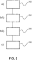
- Fig. 9 shows basic steps of an example of a method 200 for moving an imaging arrangement for X-ray imaging.
- the method 200 comprises the following steps:
- the arrangement allows for the imaging equipment to be moved over a large range of motion. Its kinematic layout enables an ergonomic working posture, easy parking, improved patient access, and provides minimal obstruction to the clinicians, or other medical equipment.
Priority Applications (6)
| Application Number | Priority Date | Filing Date | Title |
|---|---|---|---|
| EP18203289.6A EP3646789A1 (de) | 2018-10-30 | 2018-10-30 | Röntgenbildgebungsanordnung |
| EP19794571.0A EP3873345B1 (de) | 2018-10-30 | 2019-10-30 | Röntgenbildgebungsanordnung |
| US17/289,860 US11963809B2 (en) | 2018-10-30 | 2019-10-30 | X-ray imaging arrangement |
| JP2021523406A JP7159467B2 (ja) | 2018-10-30 | 2019-10-30 | X線撮像構成部 |
| PCT/EP2019/079600 WO2020089272A1 (en) | 2018-10-30 | 2019-10-30 | X-ray imaging arrangement |
| CN201980071636.6A CN113038881A (zh) | 2018-10-30 | 2019-10-30 | X射线成像装置 |
Applications Claiming Priority (1)
| Application Number | Priority Date | Filing Date | Title |
|---|---|---|---|
| EP18203289.6A EP3646789A1 (de) | 2018-10-30 | 2018-10-30 | Röntgenbildgebungsanordnung |
Publications (1)
| Publication Number | Publication Date |
|---|---|
| EP3646789A1 true EP3646789A1 (de) | 2020-05-06 |
Family
ID=64048729
Family Applications (2)
| Application Number | Title | Priority Date | Filing Date |
|---|---|---|---|
| EP18203289.6A Withdrawn EP3646789A1 (de) | 2018-10-30 | 2018-10-30 | Röntgenbildgebungsanordnung |
| EP19794571.0A Active EP3873345B1 (de) | 2018-10-30 | 2019-10-30 | Röntgenbildgebungsanordnung |
Family Applications After (1)
| Application Number | Title | Priority Date | Filing Date |
|---|---|---|---|
| EP19794571.0A Active EP3873345B1 (de) | 2018-10-30 | 2019-10-30 | Röntgenbildgebungsanordnung |
Country Status (5)
| Country | Link |
|---|---|
| US (1) | US11963809B2 (de) |
| EP (2) | EP3646789A1 (de) |
| JP (1) | JP7159467B2 (de) |
| CN (1) | CN113038881A (de) |
| WO (1) | WO2020089272A1 (de) |
Families Citing this family (2)
| Publication number | Priority date | Publication date | Assignee | Title |
|---|---|---|---|---|
| CN112386269B (zh) * | 2020-11-24 | 2022-05-17 | 中国人民解放军北部战区总医院 | 一种双机械臂式结构的车载血管造影机 |
| US20220280125A1 (en) * | 2021-03-02 | 2022-09-08 | Carestream Health, Inc. | X-ray bed |
Citations (5)
| Publication number | Priority date | Publication date | Assignee | Title |
|---|---|---|---|---|
| US4807273A (en) | 1986-10-28 | 1989-02-21 | Joerg Haendle | Voice controlled x-ray diagnostics installation |
| US6200024B1 (en) * | 1998-11-27 | 2001-03-13 | Picker International, Inc. | Virtual C-arm robotic positioning system for use in radiographic imaging equipment |
| US20110069818A1 (en) * | 2008-03-31 | 2011-03-24 | Kuka Roboter Gmbh | X-Ray Apparatus And Medical Workstation |
| US20150117603A1 (en) * | 2012-03-15 | 2015-04-30 | Fraunhofer-Gesellschaft zur Förderung der angewandten Forschung e.V. | Detector assembly for recording x-ray images of an object to be imaged |
| US20180242938A1 (en) * | 2015-08-17 | 2018-08-30 | Kawasaki Jukogyo Kabushiki Kaisha | X-ray imaging system |
Family Cites Families (16)
| Publication number | Priority date | Publication date | Assignee | Title |
|---|---|---|---|---|
| JPS5789849A (en) | 1980-11-21 | 1982-06-04 | Tokyo Shibaura Electric Co | X-ray photographing apparatus |
| US4501011A (en) | 1982-09-22 | 1985-02-19 | General Electric Company | Angulating lateral fluoroscopic suspension |
| EP0220501B1 (de) * | 1985-10-09 | 1989-05-31 | Siemens Aktiengesellschaft | Röntgendiagnostikanlage mit durch eine Steuervorrichtung verstellbaren Anlagenkomponenten |
| JPH09276258A (ja) * | 1996-04-10 | 1997-10-28 | Hitachi Medical Corp | 医用x線装置 |
| DE19625407C2 (de) * | 1996-06-25 | 2000-03-23 | Siemens Ag | Röntgenuntersuchungseinrichtung |
| DE19855213C2 (de) | 1998-11-30 | 2001-03-15 | Siemens Ag | Röntgenaufnahmeeinrichtung |
| US6431751B1 (en) * | 2000-09-18 | 2002-08-13 | Koninklijke Philips Electronics N.V. | Ceiling mounted, transportable, surgical C-arm with flat panel image receptor |
| DE10142441C1 (de) | 2001-08-31 | 2003-03-13 | Siemens Ag | Röntgenuntersuchungseinrichtung zur Deckenmontage |
| US6644852B2 (en) | 2001-11-15 | 2003-11-11 | Ge Medical Systems Global Technology | Automatically reconfigurable x-ray positioner |
| DE10161322B4 (de) | 2001-12-13 | 2009-04-02 | Siemens Ag | Röntgeneinrichtung |
| DE10215982A1 (de) * | 2002-04-11 | 2003-11-06 | Siemens Ag | Röntgeneinrichtung |
| ES2530682T3 (es) * | 2004-03-08 | 2015-03-04 | Koninkl Philips Nv | Disposición que comprende un tubo de rayos X asegurado a una montura para techo |
| US7441953B2 (en) | 2004-10-07 | 2008-10-28 | University Of Florida Research Foundation, Inc. | Radiographic medical imaging system using robot mounted source and sensor for dynamic image capture and tomography |
| US7832927B2 (en) | 2006-10-06 | 2010-11-16 | NRT—Nordisk Røntgen Teknik A/S | Manipulating system, in particular a manipulating system for manipulating an x-ray apparatus |
| US8989846B2 (en) * | 2010-08-08 | 2015-03-24 | Accuray Incorporated | Radiation treatment delivery system with outwardly movable radiation treatment head extending from ring gantry |
| CN204909474U (zh) * | 2015-07-29 | 2015-12-30 | 上海西门子医疗器械有限公司 | 移动式x射线成像设备 |
-
2018
- 2018-10-30 EP EP18203289.6A patent/EP3646789A1/de not_active Withdrawn
-
2019
- 2019-10-30 CN CN201980071636.6A patent/CN113038881A/zh active Pending
- 2019-10-30 US US17/289,860 patent/US11963809B2/en active Active
- 2019-10-30 WO PCT/EP2019/079600 patent/WO2020089272A1/en unknown
- 2019-10-30 EP EP19794571.0A patent/EP3873345B1/de active Active
- 2019-10-30 JP JP2021523406A patent/JP7159467B2/ja active Active
Patent Citations (5)
| Publication number | Priority date | Publication date | Assignee | Title |
|---|---|---|---|---|
| US4807273A (en) | 1986-10-28 | 1989-02-21 | Joerg Haendle | Voice controlled x-ray diagnostics installation |
| US6200024B1 (en) * | 1998-11-27 | 2001-03-13 | Picker International, Inc. | Virtual C-arm robotic positioning system for use in radiographic imaging equipment |
| US20110069818A1 (en) * | 2008-03-31 | 2011-03-24 | Kuka Roboter Gmbh | X-Ray Apparatus And Medical Workstation |
| US20150117603A1 (en) * | 2012-03-15 | 2015-04-30 | Fraunhofer-Gesellschaft zur Förderung der angewandten Forschung e.V. | Detector assembly for recording x-ray images of an object to be imaged |
| US20180242938A1 (en) * | 2015-08-17 | 2018-08-30 | Kawasaki Jukogyo Kabushiki Kaisha | X-ray imaging system |
Also Published As
| Publication number | Publication date |
|---|---|
| JP2022506197A (ja) | 2022-01-17 |
| US20210401390A1 (en) | 2021-12-30 |
| EP3873345B1 (de) | 2022-06-01 |
| EP3873345A1 (de) | 2021-09-08 |
| US11963809B2 (en) | 2024-04-23 |
| WO2020089272A1 (en) | 2020-05-07 |
| CN113038881A (zh) | 2021-06-25 |
| JP7159467B2 (ja) | 2022-10-24 |
Similar Documents
| Publication | Publication Date | Title |
|---|---|---|
| US6200024B1 (en) | Virtual C-arm robotic positioning system for use in radiographic imaging equipment | |
| US7431499B2 (en) | C-arm holding apparatus and X-ray diagnostic apparatus | |
| US9398675B2 (en) | Mobile imaging apparatus | |
| US7552490B2 (en) | Method and apparatus for patient loading and unloading | |
| US8819877B2 (en) | Method and device for patient loading and positioning | |
| JP6563891B2 (ja) | ロボット手術台およびハイブリッド手術室 | |
| CN110811652B (zh) | 用于移动x射线成像系统的系统和方法 | |
| EP3873345B1 (de) | Röntgenbildgebungsanordnung | |
| US6592259B2 (en) | Scaleable x-ray positioner | |
| US20110274247A1 (en) | Apparatus with Two Pairs Comprising X-Ray Source and X-Ray Detector | |
| US7658540B2 (en) | Imaging assembly stabilization device and method of use | |
| CN114098970A (zh) | 一种骨科手术机器人ct成像、导航和定位装置及系统 | |
| WO2020048896A1 (en) | An x-ray imaging device | |
| KR101528809B1 (ko) | 방사선 경사각 투시·촬영장치와 그 방법 | |
| JP2006167172A (ja) | X線診断装置 | |
| JP6708768B2 (ja) | ロボット手術台およびハイブリッド手術室 | |
| EP2692307A1 (de) | Vorrichtung zur Unterstützung und zum Anpassen einer Position eines Patientenkopfes während einer chirurgischen Operation | |
| CN114652334A (zh) | 一种基于双机械臂式的血管造影系统 | |
| CN111657982A (zh) | 三合一cbct设备 |
Legal Events
| Date | Code | Title | Description |
|---|---|---|---|
| PUAI | Public reference made under article 153(3) epc to a published international application that has entered the european phase |
Free format text: ORIGINAL CODE: 0009012 |
|
| STAA | Information on the status of an ep patent application or granted ep patent |
Free format text: STATUS: THE APPLICATION HAS BEEN PUBLISHED |
|
| AK | Designated contracting states |
Kind code of ref document: A1 Designated state(s): AL AT BE BG CH CY CZ DE DK EE ES FI FR GB GR HR HU IE IS IT LI LT LU LV MC MK MT NL NO PL PT RO RS SE SI SK SM TR |
|
| AX | Request for extension of the european patent |
Extension state: BA ME |
|
| STAA | Information on the status of an ep patent application or granted ep patent |
Free format text: STATUS: THE APPLICATION IS DEEMED TO BE WITHDRAWN |
|
| 18D | Application deemed to be withdrawn |
Effective date: 20201107 |