EP3645958B1 - Attachment arrangement for a gun module on a carrier - Google Patents
Attachment arrangement for a gun module on a carrier Download PDFInfo
- Publication number
- EP3645958B1 EP3645958B1 EP18823676.4A EP18823676A EP3645958B1 EP 3645958 B1 EP3645958 B1 EP 3645958B1 EP 18823676 A EP18823676 A EP 18823676A EP 3645958 B1 EP3645958 B1 EP 3645958B1
- Authority
- EP
- European Patent Office
- Prior art keywords
- subframe
- attachment arrangement
- carrier
- carrier frame
- module
- Prior art date
- Legal status (The legal status is an assumption and is not a legal conclusion. Google has not performed a legal analysis and makes no representation as to the accuracy of the status listed.)
- Active
Links
Images




Classifications
-
- F—MECHANICAL ENGINEERING; LIGHTING; HEATING; WEAPONS; BLASTING
- F41—WEAPONS
- F41A—FUNCTIONAL FEATURES OR DETAILS COMMON TO BOTH SMALLARMS AND ORDNANCE, e.g. CANNONS; MOUNTINGS FOR SMALLARMS OR ORDNANCE
- F41A23/00—Gun mountings, e.g. on vehicles; Disposition of guns on vehicles
- F41A23/34—Gun mountings, e.g. on vehicles; Disposition of guns on vehicles on wheeled or endless-track vehicles
-
- B—PERFORMING OPERATIONS; TRANSPORTING
- B62—LAND VEHICLES FOR TRAVELLING OTHERWISE THAN ON RAILS
- B62D—MOTOR VEHICLES; TRAILERS
- B62D21/00—Understructures, i.e. chassis frame on which a vehicle body may be mounted
- B62D21/02—Understructures, i.e. chassis frame on which a vehicle body may be mounted comprising longitudinally or transversely arranged frame members
-
- B—PERFORMING OPERATIONS; TRANSPORTING
- B62—LAND VEHICLES FOR TRAVELLING OTHERWISE THAN ON RAILS
- B62D—MOTOR VEHICLES; TRAILERS
- B62D21/00—Understructures, i.e. chassis frame on which a vehicle body may be mounted
- B62D21/09—Means for mounting load bearing surfaces
-
- B—PERFORMING OPERATIONS; TRANSPORTING
- B62—LAND VEHICLES FOR TRAVELLING OTHERWISE THAN ON RAILS
- B62D—MOTOR VEHICLES; TRAILERS
- B62D33/00—Superstructures for load-carrying vehicles
- B62D33/077—Superstructures for load-carrying vehicles characterised by the connection of the superstructure to the vehicle frame
-
- F—MECHANICAL ENGINEERING; LIGHTING; HEATING; WEAPONS; BLASTING
- F16—ENGINEERING ELEMENTS AND UNITS; GENERAL MEASURES FOR PRODUCING AND MAINTAINING EFFECTIVE FUNCTIONING OF MACHINES OR INSTALLATIONS; THERMAL INSULATION IN GENERAL
- F16B—DEVICES FOR FASTENING OR SECURING CONSTRUCTIONAL ELEMENTS OR MACHINE PARTS TOGETHER, e.g. NAILS, BOLTS, CIRCLIPS, CLAMPS, CLIPS OR WEDGES; JOINTS OR JOINTING
- F16B5/00—Joining sheets or plates, e.g. panels, to one another or to strips or bars parallel to them
- F16B5/02—Joining sheets or plates, e.g. panels, to one another or to strips or bars parallel to them by means of fastening members using screw-thread
-
- F—MECHANICAL ENGINEERING; LIGHTING; HEATING; WEAPONS; BLASTING
- F41—WEAPONS
- F41A—FUNCTIONAL FEATURES OR DETAILS COMMON TO BOTH SMALLARMS AND ORDNANCE, e.g. CANNONS; MOUNTINGS FOR SMALLARMS OR ORDNANCE
- F41A23/00—Gun mountings, e.g. on vehicles; Disposition of guns on vehicles
-
- F—MECHANICAL ENGINEERING; LIGHTING; HEATING; WEAPONS; BLASTING
- F41—WEAPONS
- F41A—FUNCTIONAL FEATURES OR DETAILS COMMON TO BOTH SMALLARMS AND ORDNANCE, e.g. CANNONS; MOUNTINGS FOR SMALLARMS OR ORDNANCE
- F41A23/00—Gun mountings, e.g. on vehicles; Disposition of guns on vehicles
- F41A23/34—Gun mountings, e.g. on vehicles; Disposition of guns on vehicles on wheeled or endless-track vehicles
- F41A23/36—Gun mountings, e.g. on vehicles; Disposition of guns on vehicles on wheeled or endless-track vehicles on trailers
-
- F—MECHANICAL ENGINEERING; LIGHTING; HEATING; WEAPONS; BLASTING
- F41—WEAPONS
- F41A—FUNCTIONAL FEATURES OR DETAILS COMMON TO BOTH SMALLARMS AND ORDNANCE, e.g. CANNONS; MOUNTINGS FOR SMALLARMS OR ORDNANCE
- F41A23/00—Gun mountings, e.g. on vehicles; Disposition of guns on vehicles
- F41A23/52—Base plates for gun mountings
-
- F—MECHANICAL ENGINEERING; LIGHTING; HEATING; WEAPONS; BLASTING
- F41—WEAPONS
- F41F—APPARATUS FOR LAUNCHING PROJECTILES OR MISSILES FROM BARRELS, e.g. CANNONS; LAUNCHERS FOR ROCKETS OR TORPEDOES; HARPOON GUNS
- F41F1/00—Launching apparatus for projecting projectiles or missiles from barrels, e.g. cannons; Harpoon guns
Definitions
- the present invention relates to an attachment arrangement for a gun module of a carrier, such as a vehicle, a craft, or a structure fixedly mounted on a foundation, the carrier comprising, fixedly mounted on the carrier, a carrier frame with at least two elongated frame portions, and the attachment arrangement further comprising an intermediate beam, on which the gun module is arranged.
- a carrier such as a vehicle, a craft, or a structure fixedly mounted on a foundation
- the carrier comprising, fixedly mounted on the carrier, a carrier frame with at least two elongated frame portions, and the attachment arrangement further comprising an intermediate beam, on which the gun module is arranged.
- the invention comprises a weapons system comprising an attachment arrangement.
- an artillery gun for example via an intermediate arm, can be placed relatively quickly and safely on any loadbearing platform/load carrier, on a caterpillar-based, wheel-based or a marine platform.
- Patent document US2004/0216597A discloses a modular artillery system, module I-IV, a first module I in the form of a gun, a second module II in the form of a charging mechanism, a third module III in the form of one or more magazines and a fourth module IV in the form of a load carrier, the modules I-III, individually or in combination, being movable between different load carriers. Secure locking of module I-III to a load carrier, module IV, is expediently carried out via a screw joint or bolted joint of known type.
- Patent document WO2011/056153A also discloses an intermediate frame and an attachment system for attaching an intermediate frame to a load carrier chassis. Attaching the intermediate frame to the chassis is carried out via one or two elastic rotatable attachments and two elastic flat attachments. The rotatable attachments are arranged with their pivot axes coincident to the center axis of the intermediate frame. It is stated that the attachments solve the problem of the inherent torsional weakness, and of an intermediate frame diagonal deformations that can arise during transport.
- US3507226 A describes a bayonet-type locking system for attaching/locking a load to a load carrier chassis.
- a series of pivotable pins are arranged in spaces underneath a loading surface and can be pivoted to active positions where they cooperate with recesses of the load to be securely locked.
- the locking system enables fast and flexible shifting between a locked and an unlocked position of the load on the chassis.
- One problem is the high recoil forces that act on a locking system during firing of artillery guns.
- One requirement is that the looking system should withstand recoil forces to a magnitude of 250-300 kN, and sometimes up to approximately 600 kN, without any play arising between an artillery gun and a load carrier.
- the problem with the abovementioned existing quick-lock systems is that they are not dimensioned for higher recoil forces, such as 600 kN. This means that secure locking between frame and chassis, or between the gun and the intermediate frame, is not without play.
- a principal object of the present invention has been to provide a quick and flexible attachment for attaching/locking an artillery gun to a load carrier chassis without being limited to only one type of load carrier.
- the attachment must withstand recoil forces of at least 250 kN, and sometimes up to 600 kN, without any play arising between the artillery gun and the load carrier.
- a further object of the present invention has been to provide an attachment that allows a relatively quick change between different artillery guns on a load carrier.
- the object is achieved if it is characterized by further comprising a superstructure module with storage spaces on top of the subframe.
- Figure 1 shows a weapons system 1, in a perspective view obliquely from behind, comprising a load carrier 2.
- the load carrier 2 can be some type of vehicle, craft or fixed structure, but in the preferred embodiment is a type of goods vehicle, such as a truck or equivalent.
- the preferred embodiment also includes a superstructure module 4 arranged on the load carrier 2.
- the superstructure module 4 is advantageously used for storing equipment and ammunition, and for containing electric and hydraulic systems etc. in the storage spaces 8.
- the gun module 3 is arranged pivotably on an intermediate beam 5, which in turn is connected to the rest of the weapons system 1 described in more detail below. Before firing the gun module 3, the gun module 3 is supported by folding support legs 6 carrying a portion of the static mass of the gun module 3 when this is angled up into a firing position. The support legs 6 also take up some of the recoil forces that result from the firing.
- the front portion of the load carrier 2 in the preferred embodiment includes a cab 7 for one or more persons driving the load carrier 2, and operating and firing the gun module 3.
- the cab 7 is advantageously equipped with protective devices of different types, for example splinter shield, bulletproof glass, radioactive shield etc., so that the safety of the personnel is maximized.
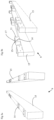
- Fig. 2 shows the components arranged on the load carrier 2, namely a subframe 10, the intermediate beam 5 and the superstructure module 4, which are all carried directly or indirectly by a carrier frame 9 on the load carrier 2.
- the carrier frame 9 is a part of the load carrier 2 and comprises at least two elongated beams 15 arranged in the longitudinal direction of the load carrier 2.
- the wheels of the load carrier 2 are suspended so that torsion forces, resulting from driving cross-country, are not transferred to the carrier frame 9 to any great extent. This is an advantage, since the gun module 3 has a rigid bottom not arranged to take up torsion forces.
- a mounting plate 13a is arranged which is intended to cooperate with a second mounting plate 13b of a fully or partly complementary design.
- the second mounting plate 13b is arranged at one end of the intermediate beam 5.
- the mounting plates 13a, 13b are, as can be seen in Fig. 2 for example, arranged across the longitudinal direction of the subframe 10. This means that forces directed in the longitudinal direction of the subframe 10, for example recoil forces when firing the gun module 3, are transferred via contact between the mounting plates 13a, 13b at right angles to their extension. In this way, large recoil forces can also be managed without the risk of damage to parts of the construction, such as fastening and connecting elements.
- the subframe 10 is arranged so that it extends above and along the carrier frame 9, at least partly in contact with the carrier frame.
- the carrier frame 9 is provided with a series of raised bosses 14 on its upper side.
- the bosses 14 are arranged in pairs, opposite each other, each on a beam 15 of the carrier frame 9. This can be seen clearly in Figs. 3a and b.
- spacer blocks 11 are arranged between the carrier frame 9 and the subframe 10.
- the spacer blocks 11 are designed with recesses 16 on its underside, so that the bosses 14 can be received in the recesses 16 and position the spacer blocks 11 on the carrier frame 9.
- the spacer blocks 11, on their upper sides have bosses 17, which in turn are received in recesses 18 on the subframe 10, for positioning this partly in relation to the spacer blocks 11, and partly in relation to the carrier frame 9.
- the spacer blocks 11 provide an opportunity to adjust the height of the weapons system 1, also depending on the height and position of the included frames 10, 11.
- the carrier frame 9 can also be arranged on a great variety of supporting structures, as well as vehicles and crafts and fixed constructions, and the need for adjusting the height therefore varies greatly.
- the appropriate final height is also affected by the gun module 3, which is to be mounted, and the desired application.
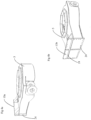
- the intermediate beam 5 and its mounting plate 13b are shown in more detail in Figs. 4a and 4b .
- the mounting plate 13b has depressions 19 in the form of crossing grooves.
- Corresponding elevations on the mounting plate 13a of the subframe 10 are insertable in the depressions 19 and prevent the mounted mounting plates 13a, 13b from slipping in the contact plane.
- screws can be arranged through the holes 24 available at the edges of the mounting plates 13a, 13b.
- Fig. 5 shows the frame and the mounting plate 13a from a different angle, so that the elevations 21 on the mounting plate 13a are visible.
- the elevations 21 and depressions 19 interact to provide a connection that can withstand high forces.
- the edges of the depressions 19 and elevations 21 press against each other with varying forces when the connection between the mounting plates 13a, 13b is subjected to lateral forces. Almost all movements when driving the load carrier 2, or when aligning and firing the gun module 3, will have component forces directed in the plane of the mounting plates 13a, 13b, and the depressions or grooves 19 and the elevations 21 are therefore most useful for providing a rigid connection between the subframe 10 and the intermediate beam 5.
- the depressions 19 and the elevations 21 have portions that are transverse to each other. This means that, in at least one portion, at least their tangents must intersect, generally at right angles. The edges of at least one portion must intersect to completely ensure that the mounting plates 13a, 13b do not rotate in relation to each other.
- Fig. 6 shows both the carrier frame 9 and the subframe 10 connected by means of joining plates 12 that are attached to respective frame 9, 10 by means of a series of screw joints.
- Fig. 7 shows the subframe 10 and the intermediate beam 5 mounted via the mounting plates 13a, 13b. This figure also shows the recesses 18 on the underside of the subframe 10.
- a protruding securing bracket 20 is arranged to provide a good attachment of the superstructure module 4.
- the protruding securing bracket 20 is securely welded or screwed to the subframe 10. If desired, the protruding securing bracket 20 is used for anchoring the superstructure module 4.
- the protruding securing bracket 20 is also used to anchor the barrel extending forwards from the weapon on the gun module 3 during transport.
- the fact that the front portion of the barrel on most guns is movable a short distance back and forth in the longitudinal direction of the barrel is advantageously used here.
- releasing from and anchoring to a protrusion on the protruding securing bracket 20 is quick when the barrel is allowed to surround the protrusion on the protruding securing bracket 20 in an anchored position.
- the front portion of the barrel moves slightly rearward, the barrel is released from the protrusion, and the barrel can be pivoted away from the protruding securing bracket 20.
- the carrier frame 9 in Fig. 7a is provided with a number of spacer blocks 11 on its raised bosses 15.
- the elevations 17 on the spacer blocks 11 are aligned with the recesses 18 on the underside of the subframe 10, as shown in Fig. 8b .
- the joining plates 12 are arranged in the area of the spacer blocks 11 on each side of the beams 15 in the subframe 10 and in the carrier frame 9. The screws are tightened through the joining plates 12 on one side and the subframe 10, spacer blocks 11 and the carrier frame 9 respectively on the other side.
- the spacer blocks can be omitted, as shown in Fig. 8d , where a direct abutment between the carrier frame 9 and the subframe 10 provides the desired build height for the current application.
- Fig. 9 shows the superstructure module 4, which in the preferred embodiment is mounted on the subframe 10, seen in a perspective view obliquely from below.
- the underside of the superstructure module 4 has longitudinal recesses 23 for receiving the integral beams 15 in the carrier frame 9 and the subframe 10.
- the superstructure module 4 is provided with anchoring means for anchoring the superstructure module 4 to the protruding securing bracket 20 and/or other parts of the subframe 10.
- the superstructure module 4 is optional in principle; however, since the recesses 23 on its underside surround and are fixed at least to the subframe 10, the superstructure module 4 is conducive to some extent to increasing the stability and strength of the construction in the weapons system 1.
- the system provides an interface between the integral parts in such a way that these do not need to be adjusted to each other. Instead, they can be coupled on the sole condition that they have the current interface in the form of the intermediate frame 10 and the mounting plates 13a, 13b.
- the superstructure module 4 can be omitted if there is no immediate need for the storage spaces it provides.
- the gun module 3 is often a howitzer, but it could be almost any type of weapon, provided that the dimension and weight limits set by the load carrier 2 are complied with. It is of particular interest that an exchange of the gun module is relatively quick.
- the gun module 3 can also be provided with different forms of encapsulations, principally for protection against environmental effects, such as rain, seawater, sand etc.
- the load carrier 2 can, as previously mentioned, be many different types of supports, such as different types of vehicles, crafts or fixed structures, not exclusively trucktype vehicles.
- the connection between the carrier frame 9 and the subframe 10 is also rigid. In practice, this is achieved by the joining plates 12 being rigid in themselves and by their attachments to the carrier frame 9 and the subframe 10 being rigid. If, however, the wheel suspension is more rigid, it needs to be taken into account that the forces from the wheels are transferred to the carrier frame 9 when driving, especially if the terrain is difficult. In order to compensate for this, the joint between the carrier frame 9 and the subframe 10 needs to be made flexible. Instead of the rigid joining plates 12, in some alternative embodiments a flexible joint is arranged between the somewhat flexible carrier frame 9 and the rigid subframe 10. Such flexible joints are advantageously provided according to the technique known to those skilled in the art.
Landscapes
- Engineering & Computer Science (AREA)
- General Engineering & Computer Science (AREA)
- Mechanical Engineering (AREA)
- Chemical & Material Sciences (AREA)
- Combustion & Propulsion (AREA)
- Transportation (AREA)
- Body Structure For Vehicles (AREA)
- Fittings On The Vehicle Exterior For Carrying Loads, And Devices For Holding Or Mounting Articles (AREA)
- Die Bonding (AREA)
- Bending Of Plates, Rods, And Pipes (AREA)
- Aiming, Guidance, Guns With A Light Source, Armor, Camouflage, And Targets (AREA)
- Buffer Packaging (AREA)
- Vehicle Step Arrangements And Article Storage (AREA)
Description
- The present invention relates to an attachment arrangement for a gun module of a carrier, such as a vehicle, a craft, or a structure fixedly mounted on a foundation, the carrier comprising, fixedly mounted on the carrier, a carrier frame with at least two elongated frame portions, and the attachment arrangement further comprising an intermediate beam, on which the gun module is arranged.
- Furthermore, the invention comprises a weapons system comprising an attachment arrangement.
- It has been known for some time to arrange cannons, howitzers and other guns on movable carriers. These are often fairly simple structures, such as wheeled gun carriers. However, in recent years carriers that are more complex are being used, carriers that are not just self-propelled, but also provide protection for one or more operators and drivers. Advantageously, such a carrier is a heavy goods vehicle with cross-country capability and which can quickly move the gun to a different position. It can also cover longer distances during a day without the need for any other goods vehicle.
- The guns arranged on the goods vehicle are more or less integrated with these and it is difficult to dismount the gun from the vehicle. In addition, it is often timeconsuming. Therefore, it is difficult to use the same weapon on different carriers, even when it is desirable to upgrade or modernize the carrier as required, or to use the gun on a completely different type of carrier, for example a vessel instead of a land-based vehicle.
EP 0 663 583 A1FR 2 893 710 A1 - In order to achieve high mobility and flexibility for an artillery system and interacting transport system, it is tactically advantageous if an artillery gun, for example via an intermediate arm, can be placed relatively quickly and safely on any loadbearing platform/load carrier, on a caterpillar-based, wheel-based or a marine platform.
- Patent document
US2004/0216597A discloses a modular artillery system, module I-IV, a first module I in the form of a gun, a second module II in the form of a charging mechanism, a third module III in the form of one or more magazines and a fourth module IV in the form of a load carrier, the modules I-III, individually or in combination, being movable between different load carriers. Secure locking of module I-III to a load carrier, module IV, is expediently carried out via a screw joint or bolted joint of known type. - Patent document
WO2011/056153A also discloses an intermediate frame and an attachment system for attaching an intermediate frame to a load carrier chassis. Attaching the intermediate frame to the chassis is carried out via one or two elastic rotatable attachments and two elastic flat attachments. The rotatable attachments are arranged with their pivot axes coincident to the center axis of the intermediate frame. It is stated that the attachments solve the problem of the inherent torsional weakness, and of an intermediate frame diagonal deformations that can arise during transport. -
US3507226 A describes a bayonet-type locking system for attaching/locking a load to a load carrier chassis. A series of pivotable pins are arranged in spaces underneath a loading surface and can be pivoted to active positions where they cooperate with recesses of the load to be securely locked. The locking system enables fast and flexible shifting between a locked and an unlocked position of the load on the chassis. - Since it is often desirable that a weapons system is made at least in part in the country of use, there is also a demand for a system where the gun and the carrier are relatively easily exchangeable. At the same time, it is important that the strength of all integral components and interconnections is sufficiently high, not only so that forces resulting during transport of the heavy gun can be taken up by the carrier, but also so that the carrier and interconnections are not damaged by the recoil forces when the gun is fired.
- One problem is the high recoil forces that act on a locking system during firing of artillery guns. One requirement is that the looking system should withstand recoil forces to a magnitude of 250-300 kN, and sometimes up to approximately 600 kN, without any play arising between an artillery gun and a load carrier. The problem with the abovementioned existing quick-lock systems is that they are not dimensioned for higher recoil forces, such as 600 kN. This means that secure locking between frame and chassis, or between the gun and the intermediate frame, is not without play.
- A principal object of the present invention has been to provide a quick and flexible attachment for attaching/locking an artillery gun to a load carrier chassis without being limited to only one type of load carrier. The attachment must withstand recoil forces of at least 250 kN, and sometimes up to 600 kN, without any play arising between the artillery gun and the load carrier.
- A further object of the present invention has been to provide an attachment that allows a relatively quick change between different artillery guns on a load carrier.
- The object on which the invention is based is achieved with an attachment arrangement as claimed in the appended independent claim 1.
- Further advantages are achieved if the attachment arrangement is furthermore provided with one or more of the features of claims 2-8.
- With reference to the weapons system, the object is achieved if it is characterized by further comprising a superstructure module with storage spaces on top of the subframe.
- Further advantages are achieved if the weapons system is furthermore provided with the features of
claim 10. - The invention will now be described with reference to the attached drawings, in which:
- Figure 1
- shows a perspective view of a weapons system according to the invention;
- Figure 2
- shows an exploded view of a portion of the weapons system according to
Fig. 1 ; - Figures 3a and
- b show perspective views of a carrier frame of a load carrier included in the weapons system according to the invention;
- Figures 4a and b
- show perspective views of an intermediate beam integral to the weapons system of
Figs. 1 and2 ; - Figure 5
- shows a perspective view of a subframe integral to the weapons system;
- Figure 6
- shows a perspective view of the interconnection of the intermediate beam, a carrier frame and the subframe;
- Figure 7
- shows a perspective view of the subframe and the intermediate beam in an interconnected state;
- Figures 8a-d
- show perspective views of the carrier frame according to Figs. 6a-b, the subframe and the intermediate beam, with and without spacer blocks; and
- Figure 9
- shows a perspective view of a superstructure module that can be optionally arranged in the weapons system.
-
Figure 1 shows a weapons system 1, in a perspective view obliquely from behind, comprising aload carrier 2. Theload carrier 2 can be some type of vehicle, craft or fixed structure, but in the preferred embodiment is a type of goods vehicle, such as a truck or equivalent. - A gun module 3, such as a howitzer or similar, is arranged on the
load carrier 2. The preferred embodiment also includes asuperstructure module 4 arranged on theload carrier 2. Thesuperstructure module 4 is advantageously used for storing equipment and ammunition, and for containing electric and hydraulic systems etc. in the storage spaces 8. - The gun module 3 is arranged pivotably on an
intermediate beam 5, which in turn is connected to the rest of the weapons system 1 described in more detail below. Before firing the gun module 3, the gun module 3 is supported by foldingsupport legs 6 carrying a portion of the static mass of the gun module 3 when this is angled up into a firing position. Thesupport legs 6 also take up some of the recoil forces that result from the firing. - The front portion of the
load carrier 2 in the preferred embodiment includes acab 7 for one or more persons driving theload carrier 2, and operating and firing the gun module 3. Thecab 7 is advantageously equipped with protective devices of different types, for example splinter shield, bulletproof glass, radioactive shield etc., so that the safety of the personnel is maximized. -
Fig. 2 shows the components arranged on theload carrier 2, namely asubframe 10, theintermediate beam 5 and thesuperstructure module 4, which are all carried directly or indirectly by acarrier frame 9 on theload carrier 2. - The
carrier frame 9 is a part of theload carrier 2 and comprises at least twoelongated beams 15 arranged in the longitudinal direction of theload carrier 2. In the preferred embodiment, the wheels of theload carrier 2 are suspended so that torsion forces, resulting from driving cross-country, are not transferred to thecarrier frame 9 to any great extent. This is an advantage, since the gun module 3 has a rigid bottom not arranged to take up torsion forces. - At one of the outer ends of the
subframe 10, a mountingplate 13a is arranged which is intended to cooperate with asecond mounting plate 13b of a fully or partly complementary design. Thesecond mounting plate 13b is arranged at one end of theintermediate beam 5. - The mounting
plates Fig. 2 for example, arranged across the longitudinal direction of thesubframe 10. This means that forces directed in the longitudinal direction of thesubframe 10, for example recoil forces when firing the gun module 3, are transferred via contact between the mountingplates - The
subframe 10 is arranged so that it extends above and along thecarrier frame 9, at least partly in contact with the carrier frame. In the preferred embodiment, thecarrier frame 9 is provided with a series of raisedbosses 14 on its upper side. Preferably, thebosses 14 are arranged in pairs, opposite each other, each on abeam 15 of thecarrier frame 9. This can be seen clearly inFigs. 3a and b. - In the preferred embodiment, spacer blocks 11 are arranged between the
carrier frame 9 and thesubframe 10. The spacer blocks 11 are designed withrecesses 16 on its underside, so that thebosses 14 can be received in therecesses 16 and position the spacer blocks 11 on thecarrier frame 9. In the preferred embodiment, the spacer blocks 11, on their upper sides, havebosses 17, which in turn are received inrecesses 18 on thesubframe 10, for positioning this partly in relation to the spacer blocks 11, and partly in relation to thecarrier frame 9. The spacer blocks 11 provide an opportunity to adjust the height of the weapons system 1, also depending on the height and position of the included frames 10, 11. Nevertheless, thecarrier frame 9 can also be arranged on a great variety of supporting structures, as well as vehicles and crafts and fixed constructions, and the need for adjusting the height therefore varies greatly. The appropriate final height is also affected by the gun module 3, which is to be mounted, and the desired application. - The
intermediate beam 5 and its mountingplate 13b are shown in more detail inFigs. 4a and 4b . In the preferred embodiment, the mountingplate 13b hasdepressions 19 in the form of crossing grooves. Corresponding elevations on the mountingplate 13a of thesubframe 10 are insertable in thedepressions 19 and prevent the mounted mountingplates plates holes 24 available at the edges of the mountingplates -
Fig. 5 shows the frame and the mountingplate 13a from a different angle, so that theelevations 21 on the mountingplate 13a are visible. According to the invention theelevations 21 anddepressions 19 interact to provide a connection that can withstand high forces. The edges of thedepressions 19 andelevations 21 press against each other with varying forces when the connection between the mountingplates load carrier 2, or when aligning and firing the gun module 3, will have component forces directed in the plane of the mountingplates grooves 19 and theelevations 21 are therefore most useful for providing a rigid connection between thesubframe 10 and theintermediate beam 5. It is also important, in order to optimize the strength of the connection, that thedepressions 19 and theelevations 21 have portions that are transverse to each other. This means that, in at least one portion, at least their tangents must intersect, generally at right angles. The edges of at least one portion must intersect to completely ensure that the mountingplates - When mounting the gun module 3 and the
intermediate beam 5 on thesubframe 10, a rigid connection between theintermediate beam 5 and thesubframe 10 is thus provided on account of the mountingplates load carrier 2 to another load carrier, also fitted with asubframe 10, can be carried out relatively quickly. Exchanging gun modules 3 on one and thesame load carrier 2 is just as simple and quick. -
Fig. 6 shows both thecarrier frame 9 and thesubframe 10 connected by means of joiningplates 12 that are attached torespective frame -
Fig. 7 shows thesubframe 10 and theintermediate beam 5 mounted via the mountingplates recesses 18 on the underside of thesubframe 10. At the end of thesubframe 10 opposite to the end where theintermediate beam 5 is mounted, a protruding securingbracket 20 is arranged to provide a good attachment of thesuperstructure module 4. The protruding securingbracket 20 is securely welded or screwed to thesubframe 10. If desired, the protruding securingbracket 20 is used for anchoring thesuperstructure module 4. - The protruding securing
bracket 20 is also used to anchor the barrel extending forwards from the weapon on the gun module 3 during transport. The fact that the front portion of the barrel on most guns is movable a short distance back and forth in the longitudinal direction of the barrel is advantageously used here. Hence, releasing from and anchoring to a protrusion on the protruding securingbracket 20 is quick when the barrel is allowed to surround the protrusion on the protruding securingbracket 20 in an anchored position. When the front portion of the barrel moves slightly rearward, the barrel is released from the protrusion, and the barrel can be pivoted away from the protruding securingbracket 20. - Mounting of the
subframe 10 and theintermediate beam 5 is shown step by step inFigs. 8 a-c . Thecarrier frame 9 in Fig. 7a is provided with a number of spacer blocks 11 on its raisedbosses 15. Theelevations 17 on the spacer blocks 11 are aligned with therecesses 18 on the underside of thesubframe 10, as shown inFig. 8b . In order to fix thecarrier frame 9, the spacer blocks 11 and the subframe 10 i relation to each other, the joiningplates 12 are arranged in the area of the spacer blocks 11 on each side of thebeams 15 in thesubframe 10 and in thecarrier frame 9. The screws are tightened through the joiningplates 12 on one side and thesubframe 10, spacer blocks 11 and thecarrier frame 9 respectively on the other side. - In some embodiments, the spacer blocks can be omitted, as shown in
Fig. 8d , where a direct abutment between thecarrier frame 9 and thesubframe 10 provides the desired build height for the current application. -
Fig. 9 shows thesuperstructure module 4, which in the preferred embodiment is mounted on thesubframe 10, seen in a perspective view obliquely from below. The underside of thesuperstructure module 4 haslongitudinal recesses 23 for receiving theintegral beams 15 in thecarrier frame 9 and thesubframe 10. In addition, in some embodiments, thesuperstructure module 4 is provided with anchoring means for anchoring thesuperstructure module 4 to the protruding securingbracket 20 and/or other parts of thesubframe 10. Thesuperstructure module 4 is optional in principle; however, since therecesses 23 on its underside surround and are fixed at least to thesubframe 10, thesuperstructure module 4 is conducive to some extent to increasing the stability and strength of the construction in the weapons system 1. - In summary, the system provides an interface between the integral parts in such a way that these do not need to be adjusted to each other. Instead, they can be coupled on the sole condition that they have the current interface in the form of the
intermediate frame 10 and the mountingplates - The invention can be varied within the scope of the attached patent claims. As mentioned, the
superstructure module 4 can be omitted if there is no immediate need for the storage spaces it provides. - The gun module 3 is often a howitzer, but it could be almost any type of weapon, provided that the dimension and weight limits set by the
load carrier 2 are complied with. It is of particular interest that an exchange of the gun module is relatively quick. - The gun module 3 can also be provided with different forms of encapsulations, principally for protection against environmental effects, such as rain, seawater, sand etc.
- The
load carrier 2 can, as previously mentioned, be many different types of supports, such as different types of vehicles, crafts or fixed structures, not exclusively trucktype vehicles. - Since the
carrier frame 9 in the preferred embodiment is rigid in principle, and the wheel suspension is such that torsion forces are not transferred to thecarrier frame 9, the connection between thecarrier frame 9 and thesubframe 10 is also rigid. In practice, this is achieved by the joiningplates 12 being rigid in themselves and by their attachments to thecarrier frame 9 and thesubframe 10 being rigid. If, however, the wheel suspension is more rigid, it needs to be taken into account that the forces from the wheels are transferred to thecarrier frame 9 when driving, especially if the terrain is difficult. In order to compensate for this, the joint between thecarrier frame 9 and thesubframe 10 needs to be made flexible. Instead of the rigid joiningplates 12, in some alternative embodiments a flexible joint is arranged between the somewhatflexible carrier frame 9 and therigid subframe 10. Such flexible joints are advantageously provided according to the technique known to those skilled in the art.
Claims (8)
- An attachment arrangement for a gun module (3) of a carrier (2), such as a vehicle, a craft, or a structure fixedly mounted on a foundation, having a fixedly mounted carrier frame (9), comprising at least two elongated frame portions, and the attachment arrangement comprising an intermediate beam (5), on which the gun module (3) can be arranged, a subframe (10) for arranging on the carrier frame (9), and a pair of interacting mounting plates (13a, 13b), arranged at the outer ends of the subframe (10) and the intermediate beam (5) respectively, for a connection between them, a first one of the interacting mounting plates (13a, 13b) being provided with a depression (19), while the other mounting plate (13a, 13b) being provided with a protrusion (21) whose form, size and position correspond to the form, size and position of the depression (19) on the first mounting plate (13a, 13b), wherein the mounting plates (13a, 13b) are arranged across the longitudinal direction of the subframe (10), whereby the protrusions (21) and depressions (19) have side edges respectively, which in a first portion are arranged substantially at right angles to the side edges of the other portion, to take up component forces that are directed across the side edges.
- The attachment arrangement according to claim 1, characterized in that the protrusions (21) and depressions (19) have side edges respectively, which in at least one portion intersect each other to prevent rotation of the mounting plates (13a, 13b) in relation to each other.
- The attachment arrangement according to any one of claims 1 to 2, characterized in that fixed joints, such as bolts, screws etc. are arranged to retain the mounting plates (13a, 13b) in contact with each other.
- The attachment arrangement according to any one of claims 1 to 3, characterized in that joining plates (12) extend along the sides of the carrier frame (9) and the subframe (10) and that they are connected to both the carrier frame (9) and the subframe (10) for joining these.
- The attachment arrangement according to any one of claims 1 to 4, characterized in that bosses (14) and corresponding recesses (18) are arranged on the carrier frame (9) and the subframe (10) respectively, for controlling these in relation to each other.
- The attachment arrangement according to claim 5, characterized in that spacer blocks (11) are arranged between the carrier frame (9) and the subframe (10) at the bosses (14) and the recesses (18) for controlling the distance between them.
- A weapons system (1) comprising an attachment arrangement according to any one of claims 1 to 6, characterized in that it further comprises a superstructure module (4) having storage spaces (8) on top of the subframe (10).
- The weapons system according to claim 7, characterized in that the gun module (3) comprises a howitzer.
Priority Applications (2)
| Application Number | Priority Date | Filing Date | Title |
|---|---|---|---|
| RS20230312A RS64152B1 (en) | 2017-06-30 | 2018-06-27 | Attachment arrangement for a gun module on a carrier |
| HRP20230390TT HRP20230390T1 (en) | 2017-06-30 | 2018-06-27 | Attachment arrangement for a gun module on a carrier |
Applications Claiming Priority (2)
| Application Number | Priority Date | Filing Date | Title |
|---|---|---|---|
| SE1700135A SE541539C2 (en) | 2017-06-30 | 2017-06-30 | Fastening device for a piece module on a carrier and a weapon system |
| PCT/SE2018/050698 WO2019004916A1 (en) | 2017-06-30 | 2018-06-27 | Attachment arrangement for a gun module on a carrier |
Publications (3)
| Publication Number | Publication Date |
|---|---|
| EP3645958A1 EP3645958A1 (en) | 2020-05-06 |
| EP3645958A4 EP3645958A4 (en) | 2021-03-24 |
| EP3645958B1 true EP3645958B1 (en) | 2023-03-01 |
Family
ID=64742548
Family Applications (1)
| Application Number | Title | Priority Date | Filing Date |
|---|---|---|---|
| EP18823676.4A Active EP3645958B1 (en) | 2017-06-30 | 2018-06-27 | Attachment arrangement for a gun module on a carrier |
Country Status (13)
| Country | Link |
|---|---|
| US (1) | US10921083B2 (en) |
| EP (1) | EP3645958B1 (en) |
| KR (1) | KR102509758B1 (en) |
| CA (1) | CA3064186A1 (en) |
| ES (1) | ES2943859T3 (en) |
| FI (1) | FI3645958T3 (en) |
| HR (1) | HRP20230390T1 (en) |
| IL (1) | IL271452B (en) |
| PL (1) | PL3645958T3 (en) |
| RS (1) | RS64152B1 (en) |
| SE (1) | SE541539C2 (en) |
| WO (1) | WO2019004916A1 (en) |
| ZA (1) | ZA201907924B (en) |
Families Citing this family (3)
| Publication number | Priority date | Publication date | Assignee | Title |
|---|---|---|---|---|
| US12319233B2 (en) * | 2019-02-21 | 2025-06-03 | Em Sil Enterprises, Inc. | Sub-frame and step assembly for truck |
| CN112026926B (en) * | 2020-08-24 | 2024-12-03 | 东风汽车集团有限公司 | Military vehicle weapon mounting structure |
| DE102024133378A1 (en) * | 2024-11-14 | 2026-05-21 | Rheinmetall MAN Military Vehicles Österreich GesmbH | COMMERCIAL VEHICLE |
Family Cites Families (18)
| Publication number | Priority date | Publication date | Assignee | Title |
|---|---|---|---|---|
| US2549835A (en) * | 1946-05-06 | 1951-04-24 | William F Mccann | Mobile gun carriage |
| AT396987B (en) * | 1982-05-21 | 1994-01-25 | Liezen Maschf | MOVABLE PROTECTION |
| US5465808A (en) | 1993-05-24 | 1995-11-14 | Loral Vought Systems Corporation | Elevating system |
| SE501401C2 (en) * | 1993-12-17 | 1995-02-06 | Bofors Ab | Ammunition management system for artillery pieces |
| US5419234A (en) | 1994-03-25 | 1995-05-30 | Sanderson; Paul H. | Aircraft support plank mounting of 40 mm machine guns |
| SG101963A1 (en) * | 2001-03-14 | 2004-02-27 | Ordnance Dev And Engineering C | Mobile artillery system |
| WO2003025494A1 (en) * | 2001-08-30 | 2003-03-27 | Krauss-Maffei Wegmann Gmbh & Co. Kg | Artillery gun with a heavy weapon arranged on a support vehicle |
| US6564690B1 (en) | 2002-08-12 | 2003-05-20 | The United States Of America As Represented By The Secretary Of The Navy | Interface pallet assembly for a helicopter-based weapon system |
| JP4133903B2 (en) * | 2004-03-30 | 2008-08-13 | 株式会社日本製鋼所 | Ryu cannon mounted on vehicle |
| KR100794861B1 (en) * | 2004-04-29 | 2008-01-14 | 비에이이 시스템즈 랜드 앤 암어먼츠 엘.피. | Mortar Deployment and Storage System |
| FR2880109B1 (en) * | 2004-12-28 | 2007-03-23 | Giat Ind Sa | TRUCK TRANSPORTABLE VEHICLE SYSTEM |
| FR2880108B1 (en) * | 2004-12-28 | 2007-03-23 | Giat Ind Sa | ARM SYSTEM COMPRISING A LIGHT VEHICLE AND METHOD OF IMPLEMENTING SUCH AN ARMS SYSTEM |
| US7481147B1 (en) | 2005-10-18 | 2009-01-27 | Contract Fabrication & Design, Llc | External, underside positioned aircraft object mounting system |
| FR2893710B1 (en) * | 2005-11-21 | 2010-02-12 | Giat Ind Sa | DEVICE FOR FASTENING A WEAPON SYSTEM ON A VEHICLE CHASSIS |
| AU2010231536B2 (en) | 2009-03-30 | 2013-07-18 | Director General, Defence Research & Development Organisation | A mobile missile launch system and method thereof |
| DE102011050537B3 (en) * | 2011-05-20 | 2012-10-25 | Krauss-Maffei Wegmann Gmbh & Co. Kg | Gun and military vehicle |
| US10240884B1 (en) * | 2013-03-14 | 2019-03-26 | The United States Of America As Represented By The Secretary Of The Navy | Mountable fixture for absorbing recoil |
| CN105283376B (en) | 2013-06-11 | 2018-04-17 | 沃尔沃卡车集团 | For component to be installed to the cross member and method of chassis frame |
-
2017
- 2017-06-30 SE SE1700135A patent/SE541539C2/en unknown
-
2018
- 2018-06-27 FI FIEP18823676.4T patent/FI3645958T3/en active
- 2018-06-27 US US16/627,306 patent/US10921083B2/en active Active
- 2018-06-27 KR KR1020207002662A patent/KR102509758B1/en active Active
- 2018-06-27 WO PCT/SE2018/050698 patent/WO2019004916A1/en not_active Ceased
- 2018-06-27 PL PL18823676.4T patent/PL3645958T3/en unknown
- 2018-06-27 HR HRP20230390TT patent/HRP20230390T1/en unknown
- 2018-06-27 EP EP18823676.4A patent/EP3645958B1/en active Active
- 2018-06-27 RS RS20230312A patent/RS64152B1/en unknown
- 2018-06-27 CA CA3064186A patent/CA3064186A1/en active Pending
- 2018-06-27 ES ES18823676T patent/ES2943859T3/en active Active
-
2019
- 2019-11-28 ZA ZA201907924A patent/ZA201907924B/en unknown
- 2019-12-15 IL IL271452A patent/IL271452B/en active IP Right Grant
Also Published As
| Publication number | Publication date |
|---|---|
| US10921083B2 (en) | 2021-02-16 |
| KR102509758B1 (en) | 2023-03-14 |
| IL271452B (en) | 2021-05-31 |
| KR20200033861A (en) | 2020-03-30 |
| PL3645958T3 (en) | 2023-05-08 |
| WO2019004916A1 (en) | 2019-01-03 |
| RS64152B1 (en) | 2023-05-31 |
| EP3645958A1 (en) | 2020-05-06 |
| HRP20230390T1 (en) | 2023-06-23 |
| US20200166305A1 (en) | 2020-05-28 |
| SE1700135A1 (en) | 2018-12-31 |
| IL271452A (en) | 2020-01-30 |
| FI3645958T3 (en) | 2023-05-03 |
| ES2943859T3 (en) | 2023-06-16 |
| EP3645958A4 (en) | 2021-03-24 |
| CA3064186A1 (en) | 2019-01-03 |
| SE541539C2 (en) | 2019-10-29 |
| ZA201907924B (en) | 2020-11-25 |
Similar Documents
| Publication | Publication Date | Title |
|---|---|---|
| US10921083B2 (en) | Attachment arrangement for a gun module on a carrier | |
| US7418897B2 (en) | Weapon system that can be carried by a truck | |
| US9649903B2 (en) | Weapons platform, military vehicle comprising a weapons platform and method for operating a weapons platform | |
| IT9021541A1 (en) | REFERENCES RELATED TO FIELD OBJECTS | |
| US8430014B2 (en) | Armored attack vehicle with helmet assembly | |
| US20200347982A1 (en) | Modular and Impactable Frame with Integrated Leveler | |
| KR100794861B1 (en) | Mortar Deployment and Storage System | |
| US8726784B2 (en) | Field gun aim | |
| EP3453671B1 (en) | Forklift for air transport and stowage procedure | |
| US5421239A (en) | Support plank-based external aircraft cargo carrying apparatus | |
| US7934445B2 (en) | Combinations of protective ballistic weapons stands and weapon tripods | |
| JPS63502369A (en) | Shock absorption movement device for curved artillery | |
| BR8806996A (en) | MULTIPLE PURPOSE CHASSIS FOR COMMERCIAL AND SPECIAL VEHICLES | |
| US10240884B1 (en) | Mountable fixture for absorbing recoil | |
| KR101560335B1 (en) | Modularized System to be Mounted for Truck | |
| EP2906898B1 (en) | Field gun | |
| RU212336U1 (en) | Mine layer on a wheeled chassis | |
| US3165973A (en) | Manner of mounting heavy arms in vehicles | |
| CA3214306C (en) | Antenna mast structure | |
| RU15516U1 (en) | SWIVELING ROTARY DEVICE OF STARTING UNIT | |
| NO864610L (en) | GUNS. | |
| US3417659A (en) | Vehicular support for a mortar | |
| AU2024259809A1 (en) | Modular Military Vehicle System |
Legal Events
| Date | Code | Title | Description |
|---|---|---|---|
| REG | Reference to a national code |
Ref country code: HR Ref legal event code: TUEP Ref document number: P20230390T Country of ref document: HR |
|
| STAA | Information on the status of an ep patent application or granted ep patent |
Free format text: STATUS: THE INTERNATIONAL PUBLICATION HAS BEEN MADE |
|
| PUAI | Public reference made under article 153(3) epc to a published international application that has entered the european phase |
Free format text: ORIGINAL CODE: 0009012 |
|
| STAA | Information on the status of an ep patent application or granted ep patent |
Free format text: STATUS: REQUEST FOR EXAMINATION WAS MADE |
|
| 17P | Request for examination filed |
Effective date: 20200130 |
|
| AK | Designated contracting states |
Kind code of ref document: A1 Designated state(s): AL AT BE BG CH CY CZ DE DK EE ES FI FR GB GR HR HU IE IS IT LI LT LU LV MC MK MT NL NO PL PT RO RS SE SI SK SM TR |
|
| AX | Request for extension of the european patent |
Extension state: BA ME |
|
| DAV | Request for validation of the european patent (deleted) | ||
| DAX | Request for extension of the european patent (deleted) | ||
| A4 | Supplementary search report drawn up and despatched |
Effective date: 20210224 |
|
| RIC1 | Information provided on ipc code assigned before grant |
Ipc: B62D 21/02 20060101ALI20210218BHEP Ipc: F41A 23/34 20060101ALI20210218BHEP Ipc: F41A 23/00 20060101AFI20210218BHEP Ipc: B62D 33/077 20060101ALI20210218BHEP Ipc: F41A 23/36 20060101ALI20210218BHEP Ipc: B62D 21/09 20060101ALI20210218BHEP |
|
| GRAP | Despatch of communication of intention to grant a patent |
Free format text: ORIGINAL CODE: EPIDOSNIGR1 |
|
| STAA | Information on the status of an ep patent application or granted ep patent |
Free format text: STATUS: GRANT OF PATENT IS INTENDED |
|
| RIC1 | Information provided on ipc code assigned before grant |
Ipc: B62D 33/077 20060101ALI20221116BHEP Ipc: B62D 21/09 20060101ALI20221116BHEP Ipc: B62D 21/02 20060101ALI20221116BHEP Ipc: F41A 23/36 20060101ALI20221116BHEP Ipc: F41A 23/34 20060101ALI20221116BHEP Ipc: F41A 23/00 20060101AFI20221116BHEP |
|
| INTG | Intention to grant announced |
Effective date: 20221205 |
|
| GRAS | Grant fee paid |
Free format text: ORIGINAL CODE: EPIDOSNIGR3 |
|
| GRAA | (expected) grant |
Free format text: ORIGINAL CODE: 0009210 |
|
| STAA | Information on the status of an ep patent application or granted ep patent |
Free format text: STATUS: THE PATENT HAS BEEN GRANTED |
|
| AK | Designated contracting states |
Kind code of ref document: B1 Designated state(s): AL AT BE BG CH CY CZ DE DK EE ES FI FR GB GR HR HU IE IS IT LI LT LU LV MC MK MT NL NO PL PT RO RS SE SI SK SM TR |
|
| REG | Reference to a national code |
Ref country code: GB Ref legal event code: FG4D |
|
| REG | Reference to a national code |
Ref country code: CH Ref legal event code: EP Ref country code: AT Ref legal event code: REF Ref document number: 1551237 Country of ref document: AT Kind code of ref document: T Effective date: 20230315 |
|
| REG | Reference to a national code |
Ref country code: DE Ref legal event code: R096 Ref document number: 602018046758 Country of ref document: DE |
|
| REG | Reference to a national code |
Ref country code: IE Ref legal event code: FG4D |
|
| REG | Reference to a national code |
Ref country code: NO Ref legal event code: T2 Effective date: 20230301 |
|
| REG | Reference to a national code |
Ref country code: ES Ref legal event code: FG2A Ref document number: 2943859 Country of ref document: ES Kind code of ref document: T3 Effective date: 20230616 |
|
| REG | Reference to a national code |
Ref country code: HR Ref legal event code: T1PR Ref document number: P20230390 Country of ref document: HR |
|
| REG | Reference to a national code |
Ref country code: LT Ref legal event code: MG9D |
|
| REG | Reference to a national code |
Ref country code: NL Ref legal event code: MP Effective date: 20230301 |
|
| REG | Reference to a national code |
Ref country code: HR Ref legal event code: ODRP Ref document number: P20230390 Country of ref document: HR Payment date: 20230601 Year of fee payment: 6 |
|
| PG25 | Lapsed in a contracting state [announced via postgrant information from national office to epo] |
Ref country code: LV Free format text: LAPSE BECAUSE OF FAILURE TO SUBMIT A TRANSLATION OF THE DESCRIPTION OR TO PAY THE FEE WITHIN THE PRESCRIBED TIME-LIMIT Effective date: 20230301 Ref country code: LT Free format text: LAPSE BECAUSE OF FAILURE TO SUBMIT A TRANSLATION OF THE DESCRIPTION OR TO PAY THE FEE WITHIN THE PRESCRIBED TIME-LIMIT Effective date: 20230301 |
|
| REG | Reference to a national code |
Ref country code: AT Ref legal event code: MK05 Ref document number: 1551237 Country of ref document: AT Kind code of ref document: T Effective date: 20230301 |
|
| PG25 | Lapsed in a contracting state [announced via postgrant information from national office to epo] |
Ref country code: SE Free format text: LAPSE BECAUSE OF FAILURE TO SUBMIT A TRANSLATION OF THE DESCRIPTION OR TO PAY THE FEE WITHIN THE PRESCRIBED TIME-LIMIT Effective date: 20230301 Ref country code: NL Free format text: LAPSE BECAUSE OF FAILURE TO SUBMIT A TRANSLATION OF THE DESCRIPTION OR TO PAY THE FEE WITHIN THE PRESCRIBED TIME-LIMIT Effective date: 20230301 Ref country code: GR Free format text: LAPSE BECAUSE OF FAILURE TO SUBMIT A TRANSLATION OF THE DESCRIPTION OR TO PAY THE FEE WITHIN THE PRESCRIBED TIME-LIMIT Effective date: 20230602 |
|
| PG25 | Lapsed in a contracting state [announced via postgrant information from national office to epo] |
Ref country code: SM Free format text: LAPSE BECAUSE OF FAILURE TO SUBMIT A TRANSLATION OF THE DESCRIPTION OR TO PAY THE FEE WITHIN THE PRESCRIBED TIME-LIMIT Effective date: 20230301 Ref country code: RO Free format text: LAPSE BECAUSE OF FAILURE TO SUBMIT A TRANSLATION OF THE DESCRIPTION OR TO PAY THE FEE WITHIN THE PRESCRIBED TIME-LIMIT Effective date: 20230301 Ref country code: PT Free format text: LAPSE BECAUSE OF FAILURE TO SUBMIT A TRANSLATION OF THE DESCRIPTION OR TO PAY THE FEE WITHIN THE PRESCRIBED TIME-LIMIT Effective date: 20230703 Ref country code: EE Free format text: LAPSE BECAUSE OF FAILURE TO SUBMIT A TRANSLATION OF THE DESCRIPTION OR TO PAY THE FEE WITHIN THE PRESCRIBED TIME-LIMIT Effective date: 20230301 Ref country code: AT Free format text: LAPSE BECAUSE OF FAILURE TO SUBMIT A TRANSLATION OF THE DESCRIPTION OR TO PAY THE FEE WITHIN THE PRESCRIBED TIME-LIMIT Effective date: 20230301 |
|
| PG25 | Lapsed in a contracting state [announced via postgrant information from national office to epo] |
Ref country code: SK Free format text: LAPSE BECAUSE OF FAILURE TO SUBMIT A TRANSLATION OF THE DESCRIPTION OR TO PAY THE FEE WITHIN THE PRESCRIBED TIME-LIMIT Effective date: 20230301 Ref country code: IS Free format text: LAPSE BECAUSE OF FAILURE TO SUBMIT A TRANSLATION OF THE DESCRIPTION OR TO PAY THE FEE WITHIN THE PRESCRIBED TIME-LIMIT Effective date: 20230701 |
|
| REG | Reference to a national code |
Ref country code: DE Ref legal event code: R097 Ref document number: 602018046758 Country of ref document: DE |
|
| PLBE | No opposition filed within time limit |
Free format text: ORIGINAL CODE: 0009261 |
|
| STAA | Information on the status of an ep patent application or granted ep patent |
Free format text: STATUS: NO OPPOSITION FILED WITHIN TIME LIMIT |
|
| PG25 | Lapsed in a contracting state [announced via postgrant information from national office to epo] |
Ref country code: MC Free format text: LAPSE BECAUSE OF FAILURE TO SUBMIT A TRANSLATION OF THE DESCRIPTION OR TO PAY THE FEE WITHIN THE PRESCRIBED TIME-LIMIT Effective date: 20230301 |
|
| PG25 | Lapsed in a contracting state [announced via postgrant information from national office to epo] |
Ref country code: SI Free format text: LAPSE BECAUSE OF FAILURE TO SUBMIT A TRANSLATION OF THE DESCRIPTION OR TO PAY THE FEE WITHIN THE PRESCRIBED TIME-LIMIT Effective date: 20230301 Ref country code: MC Free format text: LAPSE BECAUSE OF FAILURE TO SUBMIT A TRANSLATION OF THE DESCRIPTION OR TO PAY THE FEE WITHIN THE PRESCRIBED TIME-LIMIT Effective date: 20230301 Ref country code: DK Free format text: LAPSE BECAUSE OF FAILURE TO SUBMIT A TRANSLATION OF THE DESCRIPTION OR TO PAY THE FEE WITHIN THE PRESCRIBED TIME-LIMIT Effective date: 20230301 |
|
| 26N | No opposition filed |
Effective date: 20231204 |
|
| REG | Reference to a national code |
Ref country code: BE Ref legal event code: MM Effective date: 20230630 |
|
| PG25 | Lapsed in a contracting state [announced via postgrant information from national office to epo] |
Ref country code: LU Free format text: LAPSE BECAUSE OF NON-PAYMENT OF DUE FEES Effective date: 20230627 |
|
| REG | Reference to a national code |
Ref country code: IE Ref legal event code: MM4A |
|
| PG25 | Lapsed in a contracting state [announced via postgrant information from national office to epo] |
Ref country code: LU Free format text: LAPSE BECAUSE OF NON-PAYMENT OF DUE FEES Effective date: 20230627 |
|
| PG25 | Lapsed in a contracting state [announced via postgrant information from national office to epo] |
Ref country code: IE Free format text: LAPSE BECAUSE OF NON-PAYMENT OF DUE FEES Effective date: 20230627 |
|
| PG25 | Lapsed in a contracting state [announced via postgrant information from national office to epo] |
Ref country code: IE Free format text: LAPSE BECAUSE OF NON-PAYMENT OF DUE FEES Effective date: 20230627 |
|
| PG25 | Lapsed in a contracting state [announced via postgrant information from national office to epo] |
Ref country code: BE Free format text: LAPSE BECAUSE OF NON-PAYMENT OF DUE FEES Effective date: 20230630 |
|
| REG | Reference to a national code |
Ref country code: HR Ref legal event code: ODRP Ref document number: P20230390 Country of ref document: HR Payment date: 20240606 Year of fee payment: 7 |
|
| PG25 | Lapsed in a contracting state [announced via postgrant information from national office to epo] |
Ref country code: BG Free format text: LAPSE BECAUSE OF FAILURE TO SUBMIT A TRANSLATION OF THE DESCRIPTION OR TO PAY THE FEE WITHIN THE PRESCRIBED TIME-LIMIT Effective date: 20230301 |
|
| PG25 | Lapsed in a contracting state [announced via postgrant information from national office to epo] |
Ref country code: BG Free format text: LAPSE BECAUSE OF FAILURE TO SUBMIT A TRANSLATION OF THE DESCRIPTION OR TO PAY THE FEE WITHIN THE PRESCRIBED TIME-LIMIT Effective date: 20230301 |
|
| PGFP | Annual fee paid to national office [announced via postgrant information from national office to epo] |
Ref country code: FI Payment date: 20250625 Year of fee payment: 8 |
|
| PGFP | Annual fee paid to national office [announced via postgrant information from national office to epo] |
Ref country code: PL Payment date: 20250607 Year of fee payment: 8 Ref country code: DE Payment date: 20250627 Year of fee payment: 8 |
|
| PGFP | Annual fee paid to national office [announced via postgrant information from national office to epo] |
Ref country code: GB Payment date: 20250627 Year of fee payment: 8 |
|
| PGFP | Annual fee paid to national office [announced via postgrant information from national office to epo] |
Ref country code: RS Payment date: 20250602 Year of fee payment: 8 Ref country code: NO Payment date: 20250627 Year of fee payment: 8 |
|
| PGFP | Annual fee paid to national office [announced via postgrant information from national office to epo] |
Ref country code: HR Payment date: 20250618 Year of fee payment: 8 |
|
| PGFP | Annual fee paid to national office [announced via postgrant information from national office to epo] |
Ref country code: FR Payment date: 20250625 Year of fee payment: 8 |
|
| REG | Reference to a national code |
Ref country code: HR Ref legal event code: ODRP Ref document number: P20230390 Country of ref document: HR Payment date: 20250618 Year of fee payment: 8 |
|
| PG25 | Lapsed in a contracting state [announced via postgrant information from national office to epo] |
Ref country code: CY Free format text: LAPSE BECAUSE OF FAILURE TO SUBMIT A TRANSLATION OF THE DESCRIPTION OR TO PAY THE FEE WITHIN THE PRESCRIBED TIME-LIMIT; INVALID AB INITIO Effective date: 20180627 |
|
| PGFP | Annual fee paid to national office [announced via postgrant information from national office to epo] |
Ref country code: TR Payment date: 20250620 Year of fee payment: 8 |
|
| PGFP | Annual fee paid to national office [announced via postgrant information from national office to epo] |
Ref country code: CZ Payment date: 20250609 Year of fee payment: 8 |
|
| PG25 | Lapsed in a contracting state [announced via postgrant information from national office to epo] |
Ref country code: HU Free format text: LAPSE BECAUSE OF FAILURE TO SUBMIT A TRANSLATION OF THE DESCRIPTION OR TO PAY THE FEE WITHIN THE PRESCRIBED TIME-LIMIT; INVALID AB INITIO Effective date: 20180627 |
|
| PGFP | Annual fee paid to national office [announced via postgrant information from national office to epo] |
Ref country code: ES Payment date: 20250701 Year of fee payment: 8 |
|
| PGFP | Annual fee paid to national office [announced via postgrant information from national office to epo] |
Ref country code: IT Payment date: 20250619 Year of fee payment: 8 |
|
| PGFP | Annual fee paid to national office [announced via postgrant information from national office to epo] |
Ref country code: CH Payment date: 20250701 Year of fee payment: 8 |