EP3645356B2 - Verfahren zum betreiben einer elektropneumatischen feststellbremsanlage eines fahrzeugzuges - Google Patents
Verfahren zum betreiben einer elektropneumatischen feststellbremsanlage eines fahrzeugzuges Download PDFInfo
- Publication number
- EP3645356B2 EP3645356B2 EP18725116.0A EP18725116A EP3645356B2 EP 3645356 B2 EP3645356 B2 EP 3645356B2 EP 18725116 A EP18725116 A EP 18725116A EP 3645356 B2 EP3645356 B2 EP 3645356B2
- Authority
- EP
- European Patent Office
- Prior art keywords
- parking brake
- vehicle
- trailer
- control function
- trailer control
- Prior art date
- Legal status (The legal status is an assumption and is not a legal conclusion. Google has not performed a legal analysis and makes no representation as to the accuracy of the status listed.)
- Active
Links
Images
Classifications
-
- B—PERFORMING OPERATIONS; TRANSPORTING
- B60—VEHICLES IN GENERAL
- B60T—VEHICLE BRAKE CONTROL SYSTEMS OR PARTS THEREOF; BRAKE CONTROL SYSTEMS OR PARTS THEREOF, IN GENERAL; ARRANGEMENT OF BRAKING ELEMENTS ON VEHICLES IN GENERAL; PORTABLE DEVICES FOR PREVENTING UNWANTED MOVEMENT OF VEHICLES; VEHICLE MODIFICATIONS TO FACILITATE COOLING OF BRAKES
- B60T13/00—Transmitting braking action from initiating means to ultimate brake actuator with power assistance or drive; Brake systems incorporating such transmitting means, e.g. air-pressure brake systems
- B60T13/10—Transmitting braking action from initiating means to ultimate brake actuator with power assistance or drive; Brake systems incorporating such transmitting means, e.g. air-pressure brake systems with fluid assistance, drive, or release
- B60T13/66—Electrical control in fluid-pressure brake systems
- B60T13/68—Electrical control in fluid-pressure brake systems by electrically-controlled valves
- B60T13/683—Electrical control in fluid-pressure brake systems by electrically-controlled valves in pneumatic systems or parts thereof
-
- B—PERFORMING OPERATIONS; TRANSPORTING
- B60—VEHICLES IN GENERAL
- B60T—VEHICLE BRAKE CONTROL SYSTEMS OR PARTS THEREOF; BRAKE CONTROL SYSTEMS OR PARTS THEREOF, IN GENERAL; ARRANGEMENT OF BRAKING ELEMENTS ON VEHICLES IN GENERAL; PORTABLE DEVICES FOR PREVENTING UNWANTED MOVEMENT OF VEHICLES; VEHICLE MODIFICATIONS TO FACILITATE COOLING OF BRAKES
- B60T13/00—Transmitting braking action from initiating means to ultimate brake actuator with power assistance or drive; Brake systems incorporating such transmitting means, e.g. air-pressure brake systems
- B60T13/10—Transmitting braking action from initiating means to ultimate brake actuator with power assistance or drive; Brake systems incorporating such transmitting means, e.g. air-pressure brake systems with fluid assistance, drive, or release
- B60T13/66—Electrical control in fluid-pressure brake systems
- B60T13/68—Electrical control in fluid-pressure brake systems by electrically-controlled valves
-
- B—PERFORMING OPERATIONS; TRANSPORTING
- B60—VEHICLES IN GENERAL
- B60T—VEHICLE BRAKE CONTROL SYSTEMS OR PARTS THEREOF; BRAKE CONTROL SYSTEMS OR PARTS THEREOF, IN GENERAL; ARRANGEMENT OF BRAKING ELEMENTS ON VEHICLES IN GENERAL; PORTABLE DEVICES FOR PREVENTING UNWANTED MOVEMENT OF VEHICLES; VEHICLE MODIFICATIONS TO FACILITATE COOLING OF BRAKES
- B60T7/00—Brake-action initiating means
- B60T7/12—Brake-action initiating means for automatic initiation; for initiation not subject to will of driver or passenger
- B60T7/20—Brake-action initiating means for automatic initiation; for initiation not subject to will of driver or passenger specially for trailers, e.g. in case of uncoupling of or overrunning by trailer
-
- B—PERFORMING OPERATIONS; TRANSPORTING
- B60—VEHICLES IN GENERAL
- B60T—VEHICLE BRAKE CONTROL SYSTEMS OR PARTS THEREOF; BRAKE CONTROL SYSTEMS OR PARTS THEREOF, IN GENERAL; ARRANGEMENT OF BRAKING ELEMENTS ON VEHICLES IN GENERAL; PORTABLE DEVICES FOR PREVENTING UNWANTED MOVEMENT OF VEHICLES; VEHICLE MODIFICATIONS TO FACILITATE COOLING OF BRAKES
- B60T13/00—Transmitting braking action from initiating means to ultimate brake actuator with power assistance or drive; Brake systems incorporating such transmitting means, e.g. air-pressure brake systems
- B60T13/10—Transmitting braking action from initiating means to ultimate brake actuator with power assistance or drive; Brake systems incorporating such transmitting means, e.g. air-pressure brake systems with fluid assistance, drive, or release
- B60T13/66—Electrical control in fluid-pressure brake systems
- B60T13/662—Electrical control in fluid-pressure brake systems characterised by specified functions of the control system components
-
- B—PERFORMING OPERATIONS; TRANSPORTING
- B60—VEHICLES IN GENERAL
- B60T—VEHICLE BRAKE CONTROL SYSTEMS OR PARTS THEREOF; BRAKE CONTROL SYSTEMS OR PARTS THEREOF, IN GENERAL; ARRANGEMENT OF BRAKING ELEMENTS ON VEHICLES IN GENERAL; PORTABLE DEVICES FOR PREVENTING UNWANTED MOVEMENT OF VEHICLES; VEHICLE MODIFICATIONS TO FACILITATE COOLING OF BRAKES
- B60T13/00—Transmitting braking action from initiating means to ultimate brake actuator with power assistance or drive; Brake systems incorporating such transmitting means, e.g. air-pressure brake systems
- B60T13/74—Transmitting braking action from initiating means to ultimate brake actuator with power assistance or drive; Brake systems incorporating such transmitting means, e.g. air-pressure brake systems with electrical assistance or drive
-
- B—PERFORMING OPERATIONS; TRANSPORTING
- B60—VEHICLES IN GENERAL
- B60T—VEHICLE BRAKE CONTROL SYSTEMS OR PARTS THEREOF; BRAKE CONTROL SYSTEMS OR PARTS THEREOF, IN GENERAL; ARRANGEMENT OF BRAKING ELEMENTS ON VEHICLES IN GENERAL; PORTABLE DEVICES FOR PREVENTING UNWANTED MOVEMENT OF VEHICLES; VEHICLE MODIFICATIONS TO FACILITATE COOLING OF BRAKES
- B60T17/00—Component parts, details, or accessories of power brake systems not covered by groups B60T8/00, B60T13/00 or B60T15/00, or presenting other characteristic features
- B60T17/18—Safety devices; Monitoring
- B60T17/22—Devices for monitoring or checking brake systems; Signal devices
-
- B—PERFORMING OPERATIONS; TRANSPORTING
- B60—VEHICLES IN GENERAL
- B60T—VEHICLE BRAKE CONTROL SYSTEMS OR PARTS THEREOF; BRAKE CONTROL SYSTEMS OR PARTS THEREOF, IN GENERAL; ARRANGEMENT OF BRAKING ELEMENTS ON VEHICLES IN GENERAL; PORTABLE DEVICES FOR PREVENTING UNWANTED MOVEMENT OF VEHICLES; VEHICLE MODIFICATIONS TO FACILITATE COOLING OF BRAKES
- B60T2201/00—Particular use of vehicle brake systems; Special systems using also the brakes; Special software modules within the brake system controller
- B60T2201/06—Hill holder; Start aid systems on inclined road
-
- B—PERFORMING OPERATIONS; TRANSPORTING
- B60—VEHICLES IN GENERAL
- B60T—VEHICLE BRAKE CONTROL SYSTEMS OR PARTS THEREOF; BRAKE CONTROL SYSTEMS OR PARTS THEREOF, IN GENERAL; ARRANGEMENT OF BRAKING ELEMENTS ON VEHICLES IN GENERAL; PORTABLE DEVICES FOR PREVENTING UNWANTED MOVEMENT OF VEHICLES; VEHICLE MODIFICATIONS TO FACILITATE COOLING OF BRAKES
- B60T2201/00—Particular use of vehicle brake systems; Special systems using also the brakes; Special software modules within the brake system controller
- B60T2201/10—Automatic or semi-automatic parking aid systems
-
- B—PERFORMING OPERATIONS; TRANSPORTING
- B60—VEHICLES IN GENERAL
- B60T—VEHICLE BRAKE CONTROL SYSTEMS OR PARTS THEREOF; BRAKE CONTROL SYSTEMS OR PARTS THEREOF, IN GENERAL; ARRANGEMENT OF BRAKING ELEMENTS ON VEHICLES IN GENERAL; PORTABLE DEVICES FOR PREVENTING UNWANTED MOVEMENT OF VEHICLES; VEHICLE MODIFICATIONS TO FACILITATE COOLING OF BRAKES
- B60T8/00—Arrangements for adjusting wheel-braking force to meet varying vehicular or ground-surface conditions, e.g. limiting or varying distribution of braking force
- B60T8/17—Using electrical or electronic regulation means to control braking
- B60T8/1701—Braking or traction control means specially adapted for particular types of vehicles
- B60T8/1708—Braking or traction control means specially adapted for particular types of vehicles for lorries or tractor-trailer combinations
-
- B—PERFORMING OPERATIONS; TRANSPORTING
- B60—VEHICLES IN GENERAL
- B60T—VEHICLE BRAKE CONTROL SYSTEMS OR PARTS THEREOF; BRAKE CONTROL SYSTEMS OR PARTS THEREOF, IN GENERAL; ARRANGEMENT OF BRAKING ELEMENTS ON VEHICLES IN GENERAL; PORTABLE DEVICES FOR PREVENTING UNWANTED MOVEMENT OF VEHICLES; VEHICLE MODIFICATIONS TO FACILITATE COOLING OF BRAKES
- B60T8/00—Arrangements for adjusting wheel-braking force to meet varying vehicular or ground-surface conditions, e.g. limiting or varying distribution of braking force
- B60T8/32—Arrangements for adjusting wheel-braking force to meet varying vehicular or ground-surface conditions, e.g. limiting or varying distribution of braking force responsive to a speed condition, e.g. acceleration or deceleration
- B60T8/321—Arrangements for adjusting wheel-braking force to meet varying vehicular or ground-surface conditions, e.g. limiting or varying distribution of braking force responsive to a speed condition, e.g. acceleration or deceleration deceleration
- B60T8/323—Systems specially adapted for tractor-trailer combinations
Definitions
- the invention relates to a method for operating an electropneumatic parking brake system of a vehicle combination consisting of a towing vehicle and a trailer vehicle, in which after a parking operation and the immobilization of the vehicle combination when the vehicle is stationary, a trailer control function is to be activated which enables a check to be made as to whether, in the event of a reduction in the braking effect of the trailer vehicle, the vehicle combination can be held in place solely by the braking effect of a parking brake of the towing vehicle.
- a trailer control function is to be activated which enables a check to be made as to whether, in the event of a reduction in the braking effect of the trailer vehicle, the vehicle combination can be held in place solely by the braking effect of a parking brake of the towing vehicle.
- Such electropneumatic parking brake systems for vehicle trains often referred to as parking brake systems or hand brake systems, are well known.
- the functionality and control of such a parking brake system is described, for example, in the DE 10 2005 060 225 A1 described.
- the trailer control function is a state of the parking brake system in which, when the parking brake is applied, the brakes of a trailer connected to the towing vehicle are released in order to give the driver of the towing vehicle an opportunity to check whether, when the vehicle is parked, the braking effect of the parking brake of the towing vehicle alone is sufficient to prevent the entire vehicle combination from rolling away.
- Such a check is particularly necessary for trailers in which the trailer brakes could release, for example as a result of gradual pressure loss when the vehicle is parked for a longer period of time. In this case too, it must be ensured that the vehicle combination does not roll away, which must therefore be brought about by the parking brake of the towing vehicle.
- the trailer control function is usually triggered manually by the driver immediately after the vehicle combination has been parked and the parking brake has been applied, by operating a control element such as a lever or switch, and is carried out by an electronic control system.
- An actuating device for a parking brake system of a commercial vehicle which has a manually operable control element for actuating the parking brake. If the parking brake has been previously engaged, the actuating device can be manually set by the driver to a specific switching state in which a trailer control function is provided. To do this, the driver can pivot a switch rocker from a spring-loaded neutral position.
- a further actuating device for a parking brake system of a commercial vehicle with an actuating element in which the actuating device has a trailer control position, wherein a trailer control function can be activated in one of several available deflection positions of the actuating element.
- the driver can turn a spring-loaded rotary switch in its angular position.
- an electronic control of the parking brake system causes a trailer control valve to be actuated when the vehicle is stationary or the parking brake is already activated, whereby a pneumatic control connection of a trailer control valve is subjected to a reservoir pressure.
- the brakes of the trailer are released as a result of the pressure being applied. This state lasts as long as the actuating device is held in the trailer control position.
- the parking brake of the towing vehicle assigned to the trailer vehicle remains engaged.
- the control switches the trailer control valve back to its original switching position. This vents the control connection of the trailer control valve and returns the trailer vehicle's brakes to the operating state they were in before the trailer control position was activated.
- the control system ignores any actuation of the operating device into the trailer control position when the vehicle is moving.
- the DE 103 36 611 A1 describes a parking brake system of a vehicle in which an actuating lever that can be operated by a driver is arranged so that it can be pivoted manually.
- the actuating lever has a locking position in which a parking brake function is activated.
- the actuating lever can be actuated into a trailer control position and thereby a trailer control function can be activated.
- Releasing the actuating lever from this trailer control position causes the actuating lever to be returned to the locking position as a result of a return spring force.
- parking brake systems are already being developed whose control system includes an automatic locking function.
- This function causes the parking brake to be applied automatically when a parking maneuver is detected and when a control system receives a corresponding signal.
- Such a function can support the driver of a commercial vehicle and make his daily work easier.
- the driver no longer needs to actively operate the handbrake or parking brake. This can lead to the driver forgetting to operate the trailer control function and the vehicle combination may therefore be inadequately secured.
- the EP 2 199 162 A1 describes a method for operating a parking brake device with a first state in which a pressure for actuating a brake cylinder can be reduced, and with a second state in which the pressure can be maintained. In the event of a standstill with the parking brake released, the second state is assumed, and if the electrical power supply is interrupted in the second state, the first state is assumed.
- the DE 10 2007 033 694 B3 describes a parking brake for a trailer vehicle, where when a "parking position" control is operated, initially only a spring brake on the towing vehicle is activated. Only after a specified period of time has elapsed is the trailer brake activated.
- the object of the invention was to propose a method for operating an electro-pneumatic parking brake system of a vehicle combination with a trailer control function, which increases the operating comfort of the vehicle combination and at the same time ensures a high level of operational reliability.
- the invention was based on the realization that in a vehicle combination that can be operated with an automatic locking function, the mandatory trailer control function can still be activated by manual operation by the driver. However, this can impair the inherently high level of convenience of such an automatic locking function and even lead to operating errors. Such operating errors can be reliably avoided by expanding an existing automatic control of the parking brake system.
- the invention is therefore based on a method for operating an electropneumatic parking brake system of a vehicle combination which consists of a towing vehicle and a trailer vehicle, in which, after a parking process and the immobilization of the vehicle combination when the vehicle is stationary, a trailer control function is to be activated which enables a check to be made as to whether, in the event of a reduction in the braking effect of the trailer vehicle, the vehicle combination can be held in place solely by the braking effect of a parking brake of the towing vehicle.
- the invention provides that when a vehicle combination has been braked independently by an automatic locking function, the trailer control function is carried out automatically.
- the trailer control function is activated automatically makes it easier to operate the vehicle.
- the driver is relieved of the workload by eliminating the step of switching the trailer control function on and off. This is particularly advantageous if the vehicle combination is already equipped with an automatic locking function that brakes the vehicle combination in a parking position. The driver is therefore not at risk of forgetting the necessary trailer brake check after parking the vehicle combination.
- the trailer control function which is preferably carried out automatically immediately after the parking brake is applied, shows that the vehicle combination is moving or rolling when the trailer brakes are released, the driver has the option of intervening and securing the vehicle combination against unintentional rolling away.
- the trailer control function is automatically deactivated and the trailer brakes are applied again so that the entire vehicle combination brakes.
- the automatic trailer control function can be implemented as a software function in an existing electronic control system of an electro-pneumatic parking brake system. Additional hardware expenditure is not required.
- the automatic locking function detects a parking process of the vehicle combination and then brakes the vehicle combination when an ignition system of a drive motor of the towing vehicle is switched off when the vehicle is stationary and this is signaled to a control of the parking brake system, and that the trailer control function is automatically activated immediately thereafter and automatically deactivated again after the control process. This ensures that the trailer control function is not inadvertently carried out in operating situations of the vehicle combination that are not intended for it.
- the invention provides that the automatic activation and deactivation of the trailer control function can be suppressed and the trailer control function can be operated manually if the automatic locking function is also suppressed and the locking function can be operated manually, provided that the vehicle combination has an actuating device with an operating element for manual actuation of the parking brake system and for manual actuation of the trailer control function.
- the automatic activation and deactivation of the trailer control function is indicated to the driver visually, acoustically and/or haptically.
- a light display can be arranged at a suitable location in the dashboard area of the driver's cab. This means that the driver is always informed whether the trailer control function was carried out by the automatic control or not, and whether the vehicle combination, for whose safe parking he is responsible, is secured in accordance with regulations.
- the invention also relates to an electropneumatic parking brake system of a vehicle combination, such as a tractor unit with a semitrailer or a truck with a trailer, which is designed in such a way that the described method can be operated by means of it.
- a trailer control function of a vehicle combination consisting of a towing vehicle and a trailer vehicle, having an electropneumatic parking brake system, is activated manually by the driver after the parking brake has been applied.
- This can be done, for example, as in the above-mentioned EP 2 379 386 B1 by means of a rocker switch, which is tilted by the driver from a spring-loaded neutral position into a certain switching position, or as in the above-mentioned EP 1 997 700 B1 by the driver turning a spring-loaded rotary switch in its angle position to a certain switching position, or as in the above-mentioned DE 103 36 611 A1 by the driver pivoting a spring-loaded operating lever into a specific switching position.
- the parking brake of the trailer is released for the duration of the operation of the control element, as long as the driver does not release the control element again and the control element has not returned to a neutral position. It can therefore be determined whether the parking brake of the towing vehicle is able to hold the entire vehicle combination, including the unbraked trailer, applied. This is particularly necessary if the vehicle combination is to be parked for a longer period and the braking effect is achieved with ventilated brake cylinders on the trailer. If these brake cylinders are vented after a long period of time due to a loss of pressure, the braking effect of the trailer is lost, so that the vehicle combination must be held solely by the braking effect of the parking brake of the towing vehicle.
- test release of the trailer parking brakes required for the test and re-application after the test is carried out by means of an electronic control via an electro-pneumatic system which controls the relevant brake cylinders via valves and actuators in a known manner, for example as described in the publications mentioned.
- the vehicle combination is equipped with an automatic parking function, whereby the parking brake is automatically applied when the vehicle combination is parked and after the ignition is switched off, the driver would then have to manually activate the trailer control function in order to check whether the parking brake of the towing vehicle is able to hold the entire vehicle combination, including the unbraked trailer, locked.
- the driver no longer has to manually operate a control element if the parking brake has already been automatically engaged.
- the trailer control function is now activated automatically according to the invention.
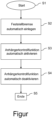
- the method starts in a first method step S1 when a parking process is detected, provided that the electropneumatic parking brake system of the vehicle combination has an automatic parking function and this is activated.
- the vehicle combination is automatically locked or braked in a second method step S2.
- the trailer control function is then automatically activated in a third method step S3.
- An electronic control temporarily releases the parking brake of the trailer. It can thus be determined whether the parking brake of the towing vehicle is able to keep the entire vehicle combination, including the unbraked trailer, locked.
- a fourth method step S4 the parking brake of the trailer is applied again and the trailer control function is automatically deactivated.
- the method ends in a fifth method step S5.
- the five process steps S1 - S5 can be part of an overall control sequence of the electropneumatic parking brake system of the vehicle combination. If it is determined that the vehicle combination is not adequately secured by the parking brake of the towing vehicle alone, the driver can initiate or carry out additional measures to secure the vehicle combination against rolling away.
Landscapes
- Engineering & Computer Science (AREA)
- Transportation (AREA)
- Mechanical Engineering (AREA)
- Regulating Braking Force (AREA)
- Braking Systems And Boosters (AREA)
Description
- Die Erfindung betrifft ein Verfahren zum Betrieb einer elektropneumatischen Feststellbremsanlage eines Fahrzeugzuges, welcher aus einem Zugfahrzeug und einem Anhängefahrzeug besteht, bei dem nach einem Parkvorgang und dem Feststellen des Fahrzeugzuges im Fahrzeugstillstand eine Anhängerkontrollfunktion zu aktivieren ist, welche eine Überprüfung ermöglicht, ob bei einem Nachlassen der Bremswirkung des Anhängefahrzeugs der Fahrzeugzug alleine durch die Bremswirkung einer Feststellbremse des Zugfahrzeugs festgehalten werden kann.
Ein solches Verfahren ist ausEP 2 719 594 A1 bekannt. - Derartige elektropneumatische Feststellbremsanlagen von Fahrzeugzügen, oft auch als Parkbremssystem oder Handbremssystem bezeichnet, sind bekannt. Die Funktionsweise und Steuerung einer derartigen Feststellbremsanlage ist beispielsweise in der
DE 10 2005 060 225 A1 beschrieben. - Als Anhängerkontrollfunktion wird dabei ein Zustand der Feststellbremsanlage bezeichnet, bei dem bei an sich angelegter Feststellbremse die Bremsen eines mit dem Zugfahrzeug verbundenen Anhängefahrzeugs gelöst werden, um dem Fahrer des Zugfahrzeuges eine Möglichkeit zu geben, zu überprüfen, ob bei abgestelltem Fahrzeug die Bremswirkung der Feststellbremse des Zugfahrzeuges alleine ausreicht, um den gesamten Fahrzeugzug am Wegrollen zu hindern. Eine derartige Überprüfung ist insbesondere bei Anhängern erforderlich, bei denen etwa infolge von schleichendem Druckverlust bei längerfristigem Abstellen des Fahrzeuges sich die Bremsen des Anhängers lösen könnten. Auch in diesem Fall muss sichergestellt sein, dass der Fahrzeugzug nicht wegrollt, was demzufolge von der Feststellbremse des Zugfahrzeuges bewirkt werden muss. Die Anhängerkontrollfunktion wird üblicherweise vom Fahrer unmittelbar nach dem Abstellen des Fahrzeugzugs und der Betätigung der Feststellbremse manuell von Hand durch Betätigen eines Bedienelements wie eines Hebels oder Schalters ausgelöst und von einer elektronischen Steuerung durchgeführt.
- Aus der
EP 2 379 386 B1 ist eine Betätigungseinrichtung für ein Parkbremssystem eines Nutzfahrzeugs bekannt, die ein manuell betätigbares Bedienelement zur Betätigung der Parkbremse aufweist. Die Betätigungseinrichtung kann vom Fahrer im Falle der zuvor eingelegten Parkbremse manuell in einen bestimmten Schaltzustand versetzt werden, in dem eine Anhängerkontrollfunktion bereitgestellt wird. Dazu kann der Fahrer eine Schalterwippe aus einer federbelasteten Neutralposition heraus verschwenken. - Aus der
EP 1 997 700 B1 ist eine weitere Betätigungseinrichtung für ein Parkbremssystem eines Nutzfahrzeugs mit einem Betätigungselement bekannt, bei der die Betätigungseinrichtung eine Anhängerkontrollstellung aufweist, wobei in einer von mehreren verfügbaren Auslenkpositionen des Betätigungselements eine Anhängerkontrollfunktion aktivierbar ist. Dazu kann der Fahrer einen federbelasteten Drehschalter in seiner Winkelstellung verdrehen. Wenn sich das Betätigungselement in der Anhängerkontrollstellung befindet, bewirkt eine elektronische Steuerung des Parkbremssystem bei stehendem Fahrzeug oder bereits aktivierter Parkbremse eine Betätigung eines Anhängerkontrollventils, wodurch ein pneumatischer Steueranschluss eines Anhängersteuerventils mit einem Vorratsdruck beaufschlagt wird. Aufgrund einer invertierenden Wirkungsweise des Anhängersteuerventils werden infolge der Druckbeaufschlagung die Bremsen des Anhängers gelöst. Dieser Zustand hält so lange an, wie die Betätigungseinrichtung in der Anhängerkontrollstellung gehalten wird. Die Parkbremse des dem Anhängefahrzeug zugeordneten Zugfahrzeugs bleibt dabei eingelegt. Sobald die Anhängerkontrollstellung verlassen wird, schaltet die Steuerung das Anhängerkontrollventil wieder in seine ursprüngliche Schaltstellung. Hierdurch wird der Steueranschluss des Anhängersteuerventils entlüftet und die Bremsen des Anhängefahrzeuges in den vor Aktivierung der Anhängerkontrollstellung liegenden Betätigungszustand zurückversetzt. Die Steuerung ignoriert eine eventuelle Betätigung der Betätigungseinrichtung in die Anhängerkontrollstellung bei fahrendem Fahrzeug. - Die
DE 103 36 611 A1 beschreibt eine Feststellbremsanlage eines Fahrzeugs, bei der ein durch einen Fahrer bedienbarer Betätigungshebel manuell verschwenkbar angeordnet ist. Der Betätigungshebel weist eine Einraststellung auf, in der eine Feststellbremsfunktion aktiviert ist. Durch eine weitere Verschwenkung des Betätigungshebels über die Einraststellung hinaus kann der Betätigungshebel in eine Anhängerkontrollstellung betätigt und dadurch eine Anhängerkontrollfunktion aktiviert werden. Ein Loslassen des Betätigungshebels aus dieser Anhängerkontrollstellung bewirkt infolge einer Rückstellfederkraft ein Zurückstellen des Betätigungshebels in die Einraststellung. - Außerdem sind bereits auch Feststellbremsanlagen in der Entwicklung, deren Steuerung eine automatische Feststellfunktion enthält. Diese Funktion bewirkt eine automatische Anwendung der Parkbremse, wenn ein Parkvorgang erkannt wird und wenn eine Steuerung ein diesbezügliches Signal empfängt. Eine derartige Funktion kann den Fahrer eines Nutzfahrzeugs unterstützen und seine tägliche Arbeit erleichtern. Bei einem Fahrzeugzug, welcher mit einer automatischen Feststellfunktion betrieben wird, entfällt die Notwendigkeit, dass der Fahrer die Handbremse beziehungsweise Parkbremse aktiv betätigt. Hierdurch kann es vorkommen, dass der Fahrer die Betätigung der Anhängerkontrollfunktion vergisst und der Fahrzeugzug demzufolge möglicherweise unzureichend gesichert ist.
- Die
EP 2 199 162 A1 beschreibt ein Verfahren zum Betrieb einer Feststellbremseinrichtung mit einem ersten Zustand, bei dem ein Druck zum Betätigen eines Bremszylinders absenkbar ist, sowie mit einem zweiten Zustand, in dem der Druck gehalten werden kann. Im Falle eines Stillstands bei gelöster Feststellbremse wird der zweite Zustand eingenommen, und falls im zweiten Zustand die elektrische Energieversorgung unterbrochen wird, wird der erste Zustand eingenommen. - Die
DE 10 2007 033 694 B3 beschreibt eine Parkbremse für ein Anhängerfahrzeug, bei der beim Betätigen eines Bedienorgans "Parkposition" zunächst nur eine Federspeicherbremse des Zugfahrzeugs aktiviert wird. Erst nach Ablauf einer vorgegebenen Zeitdauer wird danach die Bremse des Anhängers aktiviert. - Vor diesem Hintergrund lag der Erfindung die Aufgabe zugrunde, ein Verfahren zum Betrieb einer elektropneumatischen Feststellbremsanlage eines Fahrzeugzugs mit einer Anhängerkontrollfunktion vorzuschlagen, welches den Bedienkomfort des Fahrzeugzugs erhöht und zugleich eine hohe Betriebssicherheit gewährleistet.
- Die Lösung dieser Aufgabe ergibt sich aus den Merkmalen des unabhängigen Anspruchs, während vorteilhafte Ausgestaltungen und Weiterbildungen der Erfindung den zugeordneten Unteransprüchen entnehmbar sind.
- Der Erfindung lag die Erkenntnis zugrunde, dass bei einem Fahrzeugzug, der mit einer automatischen Feststellfunktion betreibbar ist, die obligatorische Anhängerkontrollfunktion nach wie vor durch eine manuelle Bedienung durch den Fahrer aktivierbar ist. Dies kann jedoch den an sich hohen Komfort einer derartigen automatischen Feststellfunktion beeinträchtigen und sogar zu Bedienungsfehlern verleiten. Derartige Bedienungsfehler sind durch eine Erweiterung einer vorhandenen automatischen Steuerung der Feststellbremsanlage zuverlässig vermeidbar.
- Die Erfindung geht daher aus von einem Verfahren zum Betrieb einer elektropneumatischen Feststellbremsanlage eines Fahrzeugzuges, welcher aus einem Zugfahrzeug und einem Anhängefahrzeug besteht, bei dem nach einem Parkvorgang und dem Feststellen des Fahrzeugzuges im Fahrzeugstillstand eine Anhängerkontrollfunktion zu aktivieren ist, welche eine Überprüfung ermöglicht, ob bei einem Nachlassen der Bremswirkung des Anhängefahrzeugs der Fahrzeugzug alleine durch die Bremswirkung einer Feststellbremse des Zugfahrzeugs festgehalten werden kann.
- Zur Lösung der gestellten Aufgabe sieht die Erfindung vor, dass dann, wenn ein Fahrzeugzug durch eine automatische Feststellfunktion selbständig festgebremst wurde, die Anhängerkontrollfunktion automatisch durchgeführt wird.
- Dadurch, dass die Anhängerkontrollfunktion automatisch aktiviert wird, vereinfacht sich die Bedienung des Fahrzeugs. Der Fahrer wird durch das Entfallen eines Arbeitsschritts zum Ein- und Ausschalten der Anhängerkontrollfunktion bei seiner Tätigkeit entlastet. Dies ist insbesondere von Vorteil, wenn der Fahrzeugzug ohnehin mit einer automatischen Feststellfunktion ausgestattet ist, welche den Fahrzeugzug in einer Parkposition festbremst. Der Fahrer kann somit nicht der Gefahr unterliegen, die notwendige Anhängerbremskontrolle nach dem Abstellen des Fahrzeugzugs zu vergessen.
- Sollte sich bei der bevorzugt unmittelbar nach der automatisierten Betätigung der Feststellbremse automatisch durchgeführten Anhängerkontrollfunktion herausstellen, dass sich der Fahrzeugzug bei gelösten Anhängerbremsen bewegt beziehungsweise anrollt, hat der Fahrer die Möglichkeit einzugreifen und den Fahrzeugzug gegen ein unbeabsichtigtes Wegrollen zu sichern. Nach der Bremsprüfung wird die Anhängerkontrollfunktion automatisch deaktiviert und die Anhängerbremsen wieder angelegt, so dass die komplette Fahrzeugkombination bremst. Die automatische Anhängerkontrollfunktion kann als eine Softwarefunktion in eine bestehende elektronische Steuerung einer elektropneumatischen Feststellbremsanlage implementiert werden. Ein zusätzlicher Hardwareaufwand ist nicht erforderlich.
- Erfindungsgemäß ist vorgesehen, dass die automatische Feststellfunktion einen Parkvorgang des Fahrzeugzugs dann erkennt und anschließend den Fahrzeugzug festbremst, wenn eine Zündanlage eines Antriebsmotors des Zugfahrzeugs im Fahrzeugstillstand ausgeschaltet ist und dieses einer Steuerung der Feststellbremsanlage signalisiert wird, und dass unmittelbar danach die Anhängerkontrollfunktion automatisch aktiviert und nach dem Kontrollvorgang automatisch wieder deaktiviert wird. Dadurch wird sichergestellt, dass die Anhängerkontrollfunktion nicht unbeabsichtigt in dafür nicht vorgesehenen Betriebssituationen des Fahrzeugzugs durchgeführt wird.
- Außerdem ist erfindungsgemäß vorgesehen, dass die automatische Aktivierung und Deaktivierung der Anhängerkontrollfunktion unterdrückt sowie die Anhängerkontrollfunktion manuell betätigt werden kann, wenn die automatische Feststellfunktion ebenfalls unterdrückt und die Feststellfunktion manuell betätigt werden kann, soweit der Fahrzeugzug eine Betätigungseinrichtung mit einem Bedienelement für eine manuelle Betätigung der Feststellbremsanlage sowie für eine manuelle Betätigung der Anhängerkontrollfunktion aufweist.
- Dadurch erhält der Fahrer die Möglichkeit, in besonderen Betriebssituationen die Anhängerkontrollfunktion manuell zu betätigen, wenn deren automatische Aktivierung oder Deaktivierung aktuell nicht gewünscht wird oder nicht möglich ist. Beispielseise könnte durch
die Betätigung eines Bedienelements die automatische Funktion ausgeschaltet und durch erneutes Betätigen des Bedienelements wieder eingeschaltet werden. So kann es beispielweise gewünscht sein, den Fahrzeugzug festzustellen und die Anhängerkontrollfunktion durchzuführen, obwohl die Zündanlage nicht ausgeschaltet ist oder nicht ausgeschaltet werden soll. Der Fahrer könnte die Bremskontrolle im Zweifelsfall auch zeitlich verlängern. Andererseits kann auf eine Bremskontrolle des Anhängefahrzeugs in bestimmten Situationen auch bewusst verzichtet werden, beispielsweise wenn ohnehin nur ein kurzer Halt vorgesehen ist und der Fahrer das Fahrzeug dabei nicht verlässt. - Erfindungsgemäß wird vorgesehen, dass die automatische Aktivierung und Deaktivierung der Anhängerkontrollfunktion dem Fahrer optisch, akustisch und/oder haptisch angezeigt wird. Dazu kann beispielsweise eine Leuchtanzeige an geeigneter Stelle im Armaturenbereich des Führerhauses angeordnet sein. Dadurch ist der Fahrer stets darüber informiert, ob die Anhängerkontrollfunktion durch die automatische Steuerung durchgeführt wurde beziehungsweise nicht durchgeführt wurde, und ob der Fahrzeugzug, für dessen betriebssicheres Abstellen er verantwortlich ist, vorschriftsmäßig gesichert ist. Schließlich betrifft die Erfindung auch eine elektropneumatische Feststellbremsanlage eines Fahrzeugzugs, wie beispielsweise einer Sattelzugmaschine mit Sattelanhänger oder einem Lastkraftwagen mit Lastanhänger, welche derartig ausgebildet ist, dass mittels dieser das beschriebene Verfahren betreibbar ist.
- Die Erfindung wird nachstehend anhand von einem in der beigefügten Zeichnung dargestellten Ausführungsbeispiel näher erläutert. In der Zeichnung zeigt die einzige Figur ein Flussdiagramm zur Veranschaulichung einer automatischen Aktivierung einer Anhängerkontrollfunktion gemäß der Erfindung.
- Nach dem bisherigen Stand der Technik wird eine Anhängerkontrollfunktion eines aus einem Zugfahrzeug und einem Anhängefahrzeug bestehenden Fahrzeugzugs, aufweisend eine elektropneumatische Feststellbremsanlage, manuell durch den Fahrer nach dem Einlegen der Feststellbremse aktiviert. Dies kann beispielsweise wie in der eingangs erwähnten
EP 2 379 386 B1 mittels einer Schalterwippe erfolgen, welche vom Fahrer aus einer federbelasteten Neutralposition heraus in einen bestimmte Schaltstellung gekippt wird, oder wie in der eingangs erwähntenEP 1 997 700 B1 , indem der Fahrer einen federbelasteten Drehschalter in seiner Winkelstellung in eine bestimmte Schaltstellung verdreht, oder wie in der eingangs erwähntenDE 103 36 611 A1 dadurch, dass der Fahrer einen federbelasteten Betätigungshebel in eine bestimmte Schaltstellung verschwenkt. - In diesem Schaltzustand wird für die Dauer der Betätigung des Bedienelements, solange der Fahrer das Bedienelement nicht wieder loslässt und dieses in eine Neutralposition nicht wieder zurückgekehrt ist, die Feststellbremse des Anhängefahrzeugs gelöst. Es kann somit festgestellt werden, ob die Feststellbremse des Zugfahrzeugs in der Lage ist, den gesamten Fahrzeugzug einschließlich des ungebremsten Anhängefahrzeugs festgestellt zu halten. Dies ist insbesondere dann erforderlich, wenn der Fahrzeugzug länger abgestellt werden soll und die Bremswirkung bei belüfteten Bremszylindern am Anhängefahrzeug erreicht wird. Wenn nach längerer Zeit durch einen Druckverlust diese Bremszylinder entlüftet sind, entfällt nämlich die Bremswirkung des Anhängefahrzeugs, so dass der Fahrzeugzug allein mittels der Bremswirkung der Feststellbremse des Zugfahrzeugs gehalten werden muss. Das für die Prüfung notwendige testweise Lösen und nach der Prüfung erneute Anlegen der Anhängerfeststellbremsen erfolgt mittels einer elektronischen Steuerung über ein elektropneumatisches System, welches die betreffenden Bremszylinder über Ventile und Stellglieder in bekannter Weise ansteuert, beispielsweise wie in den erwähnten Druckschriften beschrieben.
- Wenn nun der Fahrzeugzug mit einer automatischen Feststellfunktion ausgestattet ist, wodurch beim Parken des Fahrzeugzugs und nach dem Ausschalten der Zündung automatisch die Feststellbremse eingelegt wird, müsste der Fahrer eigentlich anschließend noch manuell die Anhängerkontrollfunktion aktivieren, um zu kontrollieren, ob die Feststellbremse des Zugfahrzeugs in der Lage ist, den gesamten Fahrzeugzug einschließlich des ungebremsten Anhängefahrzeugs festgestellt zu halten.
- Gemäß der Erfindung muss der Fahrer im Unterschied dazu nun nicht mehr manuell ein Bedienelement betätigen, wenn die Feststellbremse bereits automatisch eingelegt wurde. Wie aus dem Flussdiagramm gemäß der einzigen Figur hervorgeht, erfolgt die Aktivierung der Anhängerkontrollfunktion nunmehr gemäß der Erfindung automatisch.
- Demnach startet das Verfahren in einem ersten Verfahrensschritt S1 bei einem erkannten Parkvorgang, sofern die elektropneumatische Feststellbremsanlage des Fahrzeugzugs eine automatische Feststellfunktion aufweist und diese aktiviert ist. Der Fahrzeugzug wird nach dem Parken und dem Ausschalten der Zündung der Antriebsmaschine in einem zweiten Verfahrensschritt S2 automatisch festgestellt beziehungsweise festgebremst. Anschließend wird die Anhängerkontrollfunktion in einem dritten Verfahrensschritt S3 automatisch aktiviert. Eine elektronische Steuerung löst dabei temporär die Feststellbremse des Anhängefahrzeugs. Es kann somit festgestellt werden, ob die Feststellbremse des Zugfahrzeugs in der Lage ist, den gesamten Fahrzeugzug einschließlich des ungebremsten Anhängefahrzeugs festgestellt zu halten. In einem vierten Verfahrensschritt S4 wird die Feststellbremse des Anhängefahrzeugs wieder eingelegt und die Anhängerkontrollfunktion automatisch deaktiviert. Das Verfahren endet in einem fünften Verfahrensschritt S5.
- Die fünf Verfahrensschritte S1 - S5 können Teil eines gesamten Steuerungsablaufs der elektropneumatischen Feststellbremsanlage des Fahrzeugzugs sein. Falls festgestellt wird, dass der Fahrzeugzug durch die Feststellbremse des Zugfahrzeugs alleine nur unzureichend gesichert ist, kann der Fahrer zusätzliche Maßnahmen zur Sicherung des Fahrzeugzugs gegen Wegrollen einleiten beziehungsweise durchführen.
Claims (2)
- Verfahren zum Betrieb einer elektropneumatischen Feststellbremsanlage eines Fahrzeugzuges, welcher aus einem Zugfahrzeug und einem Anhängefahrzeug besteht, bei dem nach einem Parkvorgang und dem Feststellen des Fahrzeugzuges im Fahrzeugstillstand eine Anhängerkontrollfunktion zu aktivieren ist, welche eine Überprüfung ermöglicht, ob bei einem Nachlassen der Bremswirkung des Anhängefahrzeugs der Fahrzeugzug alleine durch die Bremswirkung einer Feststellbremse des Zugfahrzeugs festgehalten werden kann, bei dem dann, wenn ein Fahrzeugzug durch eine automatische Feststellfunktion selbständig festgebremst wurde, die Anhängerkontrollfunktion automatisch durchgeführt wird, dadurch gekennzeichnet, dass die automatische Aktivierung und Deaktivierung der Anhängerkontrollfunktion dem Fahrer optisch, akustisch und/oder haptisch angezeigt wird, wobei die automatische Feststellfunktion einen Parkvorgang des Fahrzeugzugs dann erkennt und anschließend den Fahrzeugzug festbremst, wenn eine Zündanlage eines Antriebsmotors des Zugfahrzeugs im Fahrzeugstillstand ausgeschaltet ist und dieses einer Steuerung der Feststellbremsanlage signalisiert wird, und dass unmittelbar danach die Anhängerkontrollfunktion automatisch aktiviert und nach dem Kontrollvorgang automatisch wieder deaktiviert wird, und wobei die automatische Aktivierung und Deaktivierung der Anhängerkontrollfunktion unterdrückt sowie die Anhängerkontrollfunktion manuell betätigt werden kann, wenn die automatische Feststellfunktion ebenfalls unterdrückt und die Feststellfunktion manuell betätigt werden kann, soweit der Fahrzeugzug eine Betätigungseinrichtung mit einem Bedienelement für eine manuelle Betätigung der Feststellbremsanlage sowie für eine manuelle Betätigung der Anhängerkontrollfunktion aufweist.
- Elektropneumatische Feststellbremsanlage eines Fahrzeugzugs, welche zur Durchführung eines Verfahrens nach Verfahrensanspruch 1 betreibbar ist.
Applications Claiming Priority (2)
| Application Number | Priority Date | Filing Date | Title |
|---|---|---|---|
| DE102017006006.1A DE102017006006A1 (de) | 2017-06-26 | 2017-06-26 | Verfahren zum Betrieb einer elektropneumatischen Feststellbremsanlage eines Fahrzeugzuges |
| PCT/EP2018/060841 WO2019001801A1 (de) | 2017-06-26 | 2018-04-27 | Verfahren zum betreiben einer elektropneumatischen feststellbremsanlage eines fahrzeugzuges |
Publications (3)
| Publication Number | Publication Date |
|---|---|
| EP3645356A1 EP3645356A1 (de) | 2020-05-06 |
| EP3645356B1 EP3645356B1 (de) | 2021-02-24 |
| EP3645356B2 true EP3645356B2 (de) | 2024-11-27 |
Family
ID=62186394
Family Applications (1)
| Application Number | Title | Priority Date | Filing Date |
|---|---|---|---|
| EP18725116.0A Active EP3645356B2 (de) | 2017-06-26 | 2018-04-27 | Verfahren zum betreiben einer elektropneumatischen feststellbremsanlage eines fahrzeugzuges |
Country Status (5)
| Country | Link |
|---|---|
| US (1) | US11292445B2 (de) |
| EP (1) | EP3645356B2 (de) |
| CN (1) | CN110869257B (de) |
| DE (1) | DE102017006006A1 (de) |
| WO (1) | WO2019001801A1 (de) |
Families Citing this family (3)
| Publication number | Priority date | Publication date | Assignee | Title |
|---|---|---|---|---|
| DE102018121311A1 (de) | 2018-08-31 | 2020-03-05 | Knorr-Bremse Systeme für Nutzfahrzeuge GmbH | Verfahren, Steuergerät und Steuersystem zum Steuern eines Feststellbremssystems für ein Fahrzeuggespann mit einem Zugfahrzeug und einem Anhänger |
| US11718287B2 (en) * | 2020-12-09 | 2023-08-08 | Bendix Commercial Vehicle Systems Llc | Automated system and method for parking a commercial vehicle |
| US12315312B2 (en) * | 2022-12-02 | 2025-05-27 | Bendix Commercial Vehicle Systems Llc | Systems and method for identifying tractors associated with faults at a trailer or dolly |
Citations (13)
| Publication number | Priority date | Publication date | Assignee | Title |
|---|---|---|---|---|
| DE10353056A1 (de) † | 2003-11-13 | 2005-06-02 | Knorr-Bremse Systeme für Nutzfahrzeuge GmbH | Betätigungseinrichtung einer elektrischen Parkbremse eines Fahrzeugs |
| DE102004010743A1 (de) † | 2004-03-05 | 2006-01-19 | Wabco Gmbh & Co.Ohg | Elektrisch gesteuerte pneumatische Bremsanlage für ein Fahrzeug |
| DE102005043607A1 (de) † | 2005-09-06 | 2007-03-15 | Knorr-Bremse Systeme für Nutzfahrzeuge GmbH | Verfahren zum Steuern einer elektrischen Feststellbremse eines Nutzfahrzeugs |
| DE102008006264B3 (de) † | 2008-01-25 | 2009-04-30 | Knorr-Bremse Systeme für Nutzfahrzeuge GmbH | Fahrzeugfeststellbremse und Verfahren zum Betreiben einer Fahrzeugfeststellbremse |
| DE102008006265A1 (de) † | 2008-01-25 | 2009-08-06 | Knorr-Bremse Systeme für Nutzfahrzeuge GmbH | Feststellbremssystem für ein Fahrzeug und Verfahren zum Betreiben eines Feststellbremssystems |
| DE102008018470A1 (de) † | 2008-04-11 | 2009-10-29 | Knorr-Bremse Systeme für Nutzfahrzeuge GmbH | Feststellbremse mit Testfunktion und Verfahren zum Ausführen einer Testfunktion |
| DE102008027732B3 (de) † | 2008-06-11 | 2010-01-07 | Knorr-Bremse Systeme für Nutzfahrzeuge GmbH | Parkbremsventilanordnung |
| DE102007042316B4 (de) † | 2006-11-16 | 2010-01-07 | Knorr-Bremse Systeme für Nutzfahrzeuge GmbH | Elektronisches Bremssystem für ein Nutzfahrzeug und Verfahren zum Steuern eines elektronischen Bremssystems |
| DE102008032709A1 (de) † | 2008-07-11 | 2010-01-14 | Knorr-Bremse Systeme für Nutzfahrzeuge GmbH | Drehgeber und elektrisch betätigbare Feststellbremsanlage mit einem Drehgeber |
| DE102008064077A1 (de) † | 2008-12-19 | 2010-07-01 | Wabco Gmbh | Betätigungseinrichtung sowie Verfahren zum Betätigen einer derartigen Betätigungseinrichtung |
| EP2719594A1 (de) † | 2012-10-15 | 2014-04-16 | KNORR-BREMSE Systeme für Nutzfahrzeuge GmbH | Verfahren für den Betrieb eines elektrisch betätigten Parkbremssystems und Steuervorrichtung eines elektrisch betätigten Parkbremssystems |
| DE102014108681B3 (de) † | 2014-04-11 | 2015-04-30 | Knorr-Bremse Systeme für Nutzfahrzeuge GmbH | Elektro-pneumatische Federspeicherbremseinrichtung eines Kraftfahrzeugs mit sprunghaftem Druckanstieg beim Bremslösen |
| DE102016006527A1 (de) † | 2015-06-10 | 2016-12-15 | Scania Cv Ab | Verfahren und System zum sicheren Abstellen eines Fahrzeugs mit einer Zugeinheit und einer Anhängereinheit |
Family Cites Families (11)
| Publication number | Priority date | Publication date | Assignee | Title |
|---|---|---|---|---|
| US4550953A (en) * | 1983-12-16 | 1985-11-05 | Allied Corporation | Electro-pneumatic control for a vehicle fluid pressure braking system |
| DE10336611A1 (de) | 2003-08-08 | 2005-03-03 | Wabco Gmbh & Co.Ohg | Druckmittelbetriebene Bremsanlage für ein Fahrzeug |
| DE102005058799A1 (de) * | 2005-12-09 | 2007-06-14 | Wabco Gmbh | Elektropneumatische Bremssteuerungseinrichtung |
| DE102005060225A1 (de) | 2005-12-16 | 2007-06-21 | Wabco Gmbh | Elektropneumatische Bremssteuerungseinrichtung |
| DE102006041011A1 (de) * | 2006-08-31 | 2008-03-06 | Wabco Gmbh | Ventileinheit für eine elektropneumatische Bremssteuerungseinrichtung |
| DE102007025814A1 (de) | 2007-06-02 | 2008-12-04 | Wabco Gmbh | Betätigungseinrichtung für eine Bremsanlage |
| DE102007033694B3 (de) * | 2007-07-19 | 2008-12-04 | Knorr-Bremse Systeme für Nutzfahrzeuge GmbH | Parkbremse für ein Anhängerfahrzeug |
| DE102008047632A1 (de) * | 2008-09-17 | 2010-03-25 | Knorr-Bremse Systeme für Nutzfahrzeuge GmbH | Feststellbremsanlage |
| DE102008063952A1 (de) | 2008-12-19 | 2010-06-24 | Wabco Gmbh | Verfahren zum Betrieb einer Feststellbremseinrichtung, Feststellbremseinrichtung, Bremsanlage zur Durchführung des Verfahrens, Bremsanlage mit dieser Feststellbremseinrichtung sowie Fahrzeug zur Durchführung des Verfahrens bzw. mit dieser Feststellbremseinrichtung bzw. mit dieser Bremsanlage |
| CN201347060Y (zh) * | 2008-12-31 | 2009-11-18 | 中国第一汽车集团公司 | 带驻车检测功能的双回路手动阀 |
| DE102013021681A1 (de) * | 2013-12-19 | 2015-06-25 | Wabco Gmbh | Elektropneumatisches Bremssystem für ein Anhängefahrzeug |
-
2017
- 2017-06-26 DE DE102017006006.1A patent/DE102017006006A1/de active Pending
-
2018
- 2018-04-27 US US16/625,806 patent/US11292445B2/en active Active
- 2018-04-27 EP EP18725116.0A patent/EP3645356B2/de active Active
- 2018-04-27 CN CN201880035798.XA patent/CN110869257B/zh active Active
- 2018-04-27 WO PCT/EP2018/060841 patent/WO2019001801A1/de not_active Ceased
Patent Citations (13)
| Publication number | Priority date | Publication date | Assignee | Title |
|---|---|---|---|---|
| DE10353056A1 (de) † | 2003-11-13 | 2005-06-02 | Knorr-Bremse Systeme für Nutzfahrzeuge GmbH | Betätigungseinrichtung einer elektrischen Parkbremse eines Fahrzeugs |
| DE102004010743A1 (de) † | 2004-03-05 | 2006-01-19 | Wabco Gmbh & Co.Ohg | Elektrisch gesteuerte pneumatische Bremsanlage für ein Fahrzeug |
| DE102005043607A1 (de) † | 2005-09-06 | 2007-03-15 | Knorr-Bremse Systeme für Nutzfahrzeuge GmbH | Verfahren zum Steuern einer elektrischen Feststellbremse eines Nutzfahrzeugs |
| DE102007042316B4 (de) † | 2006-11-16 | 2010-01-07 | Knorr-Bremse Systeme für Nutzfahrzeuge GmbH | Elektronisches Bremssystem für ein Nutzfahrzeug und Verfahren zum Steuern eines elektronischen Bremssystems |
| DE102008006264B3 (de) † | 2008-01-25 | 2009-04-30 | Knorr-Bremse Systeme für Nutzfahrzeuge GmbH | Fahrzeugfeststellbremse und Verfahren zum Betreiben einer Fahrzeugfeststellbremse |
| DE102008006265A1 (de) † | 2008-01-25 | 2009-08-06 | Knorr-Bremse Systeme für Nutzfahrzeuge GmbH | Feststellbremssystem für ein Fahrzeug und Verfahren zum Betreiben eines Feststellbremssystems |
| DE102008018470A1 (de) † | 2008-04-11 | 2009-10-29 | Knorr-Bremse Systeme für Nutzfahrzeuge GmbH | Feststellbremse mit Testfunktion und Verfahren zum Ausführen einer Testfunktion |
| DE102008027732B3 (de) † | 2008-06-11 | 2010-01-07 | Knorr-Bremse Systeme für Nutzfahrzeuge GmbH | Parkbremsventilanordnung |
| DE102008032709A1 (de) † | 2008-07-11 | 2010-01-14 | Knorr-Bremse Systeme für Nutzfahrzeuge GmbH | Drehgeber und elektrisch betätigbare Feststellbremsanlage mit einem Drehgeber |
| DE102008064077A1 (de) † | 2008-12-19 | 2010-07-01 | Wabco Gmbh | Betätigungseinrichtung sowie Verfahren zum Betätigen einer derartigen Betätigungseinrichtung |
| EP2719594A1 (de) † | 2012-10-15 | 2014-04-16 | KNORR-BREMSE Systeme für Nutzfahrzeuge GmbH | Verfahren für den Betrieb eines elektrisch betätigten Parkbremssystems und Steuervorrichtung eines elektrisch betätigten Parkbremssystems |
| DE102014108681B3 (de) † | 2014-04-11 | 2015-04-30 | Knorr-Bremse Systeme für Nutzfahrzeuge GmbH | Elektro-pneumatische Federspeicherbremseinrichtung eines Kraftfahrzeugs mit sprunghaftem Druckanstieg beim Bremslösen |
| DE102016006527A1 (de) † | 2015-06-10 | 2016-12-15 | Scania Cv Ab | Verfahren und System zum sicheren Abstellen eines Fahrzeugs mit einer Zugeinheit und einer Anhängereinheit |
Also Published As
| Publication number | Publication date |
|---|---|
| EP3645356A1 (de) | 2020-05-06 |
| WO2019001801A8 (de) | 2019-12-26 |
| WO2019001801A1 (de) | 2019-01-03 |
| DE102017006006A1 (de) | 2018-12-27 |
| EP3645356B1 (de) | 2021-02-24 |
| US20210155216A1 (en) | 2021-05-27 |
| CN110869257A (zh) | 2020-03-06 |
| US11292445B2 (en) | 2022-04-05 |
| CN110869257B (zh) | 2022-06-03 |
Similar Documents
| Publication | Publication Date | Title |
|---|---|---|
| EP3247596B2 (de) | Elektronisches bremssystem für eine druckluftbremsanlage eines nutzfahrzeugs | |
| EP2240352B1 (de) | Parkbremseinrichtung | |
| EP4396049B1 (de) | Verfahren zum betreiben eines elektropneumatischen bremssystems, ausfallsicherheitsventileinheit, elektropneumatisches bremssystem, fahrzeug | |
| EP1997700B1 (de) | Betätigungseinrichtung für eine Bremsanlage | |
| EP3111112B1 (de) | Verfahren und steuervorrichtung zur betätigung einer bremseinrichtung eines ein automatikgetriebe aufweisenden antriebsstrangs eines fahrzeugs | |
| EP4069559B1 (de) | Monostabil und fehlertolerant ausgelegte feststellbremsventilanordnung | |
| EP2603406B1 (de) | Verfahren zum absichern einer elektrisch betätigten feststellbremse | |
| EP3971046B1 (de) | Ventilanordnung eines zugfahrzeugs zur steuerung einer pneumatischen bremsanlage eines anhängerfahrzeugs und verfahren zu deren steuerung | |
| EP3292031B1 (de) | Verfahren zum betrieb eines parkbremssystems für nutzfahrzeuge, sowie vorrichtung hierzu | |
| EP4247676B1 (de) | Ausfallsicherheitsventileinheit, elektronisch steuerbares pneumatisches bremssystem, fahrzeug, verfahren | |
| EP3645356B2 (de) | Verfahren zum betreiben einer elektropneumatischen feststellbremsanlage eines fahrzeugzuges | |
| EP2416993A1 (de) | Verfahren zum betreiben einer bremsanlage, bremsanlage und kraftfahrzeug mit bremsanlage | |
| DE102007042316A1 (de) | Elektronisches Bremssystem für ein Nutzfahrzeug und Verfahren zum Steuern eines elektronischen Bremssystems | |
| DE102006013509A1 (de) | Elektrische Parkbremse mit einem Bedienelement zur Umschaltung in einen Servicemodus | |
| DE10238870B4 (de) | Verfahren zum Durchführen eines selbsttätigen Bremsvorgangs für ein Kraftfahrzeug sowie Kraftfahrzeug | |
| WO2015131886A1 (de) | Automatische steuerung eines fahrtrichtungsanzeigers eines fahrzeugs | |
| DE102009016982B4 (de) | Verfahren zum Betreiben einer Bremseinrichtung eines Haltestellen anfahrenden Kraftfahrzeugs | |
| EP3360737B1 (de) | Verfahren und vorrichtung zum steuern einer elektrischen parkbremse | |
| EP4405216B1 (de) | Verfahren zum betreiben eines bremssystems eines nutzfahrzeuges | |
| DE10153038A1 (de) | Elektronisch angesteuerte Parkbremse | |
| EP3844039B1 (de) | Verfahren, steuergerät und steuersystem zum steuern eines feststellbremssystems für ein fahrzeuggespann mit einem zugfahrzeug und einem anhänger | |
| DE102014217393A1 (de) | Verfahren und Vorrichtung zum Betreiben eines Kraftfahrzeugs, Kraftfahrzeug | |
| DE102019210258A1 (de) | Fahrzeugsteuergerät mit einer Auto-Hold Funktion | |
| DE102012023403A1 (de) | Kraftfahrzeugbremssystem |
Legal Events
| Date | Code | Title | Description |
|---|---|---|---|
| STAA | Information on the status of an ep patent application or granted ep patent |
Free format text: STATUS: UNKNOWN |
|
| STAA | Information on the status of an ep patent application or granted ep patent |
Free format text: STATUS: THE INTERNATIONAL PUBLICATION HAS BEEN MADE |
|
| PUAI | Public reference made under article 153(3) epc to a published international application that has entered the european phase |
Free format text: ORIGINAL CODE: 0009012 |
|
| STAA | Information on the status of an ep patent application or granted ep patent |
Free format text: STATUS: REQUEST FOR EXAMINATION WAS MADE |
|
| 17P | Request for examination filed |
Effective date: 20200127 |
|
| AK | Designated contracting states |
Kind code of ref document: A1 Designated state(s): AL AT BE BG CH CY CZ DE DK EE ES FI FR GB GR HR HU IE IS IT LI LT LU LV MC MK MT NL NO PL PT RO RS SE SI SK SM TR |
|
| AX | Request for extension of the european patent |
Extension state: BA ME |
|
| DAV | Request for validation of the european patent (deleted) | ||
| DAX | Request for extension of the european patent (deleted) | ||
| GRAP | Despatch of communication of intention to grant a patent |
Free format text: ORIGINAL CODE: EPIDOSNIGR1 |
|
| STAA | Information on the status of an ep patent application or granted ep patent |
Free format text: STATUS: GRANT OF PATENT IS INTENDED |
|
| INTG | Intention to grant announced |
Effective date: 20201105 |
|
| GRAS | Grant fee paid |
Free format text: ORIGINAL CODE: EPIDOSNIGR3 |
|
| GRAA | (expected) grant |
Free format text: ORIGINAL CODE: 0009210 |
|
| STAA | Information on the status of an ep patent application or granted ep patent |
Free format text: STATUS: THE PATENT HAS BEEN GRANTED |
|
| AK | Designated contracting states |
Kind code of ref document: B1 Designated state(s): AL AT BE BG CH CY CZ DE DK EE ES FI FR GB GR HR HU IE IS IT LI LT LU LV MC MK MT NL NO PL PT RO RS SE SI SK SM TR |
|
| REG | Reference to a national code |
Ref country code: CH Ref legal event code: EP |
|
| REG | Reference to a national code |
Ref country code: AT Ref legal event code: REF Ref document number: 1364065 Country of ref document: AT Kind code of ref document: T Effective date: 20210315 |
|
| REG | Reference to a national code |
Ref country code: DE Ref legal event code: R081 Ref document number: 502018004053 Country of ref document: DE Owner name: ZF CV SYSTEMS EUROPE BV, BE Free format text: FORMER OWNER: WABCO GMBH, 30453 HANNOVER, DE Ref country code: DE Ref legal event code: R081 Ref document number: 502018004053 Country of ref document: DE Owner name: ZF CV SYSTEMS HANNOVER GMBH, DE Free format text: FORMER OWNER: WABCO GMBH, 30453 HANNOVER, DE Ref country code: IE Ref legal event code: FG4D Free format text: LANGUAGE OF EP DOCUMENT: GERMAN |
|
| REG | Reference to a national code |
Ref country code: DE Ref legal event code: R096 Ref document number: 502018004053 Country of ref document: DE |
|
| RAP4 | Party data changed (patent owner data changed or rights of a patent transferred) |
Owner name: ZF CV SYSTEMS HANNOVER GMBH |
|
| REG | Reference to a national code |
Ref country code: LT Ref legal event code: MG9D |
|
| REG | Reference to a national code |
Ref country code: NL Ref legal event code: MP Effective date: 20210224 |
|
| PG25 | Lapsed in a contracting state [announced via postgrant information from national office to epo] |
Ref country code: NO Free format text: LAPSE BECAUSE OF FAILURE TO SUBMIT A TRANSLATION OF THE DESCRIPTION OR TO PAY THE FEE WITHIN THE PRESCRIBED TIME-LIMIT Effective date: 20210524 Ref country code: PT Free format text: LAPSE BECAUSE OF FAILURE TO SUBMIT A TRANSLATION OF THE DESCRIPTION OR TO PAY THE FEE WITHIN THE PRESCRIBED TIME-LIMIT Effective date: 20210624 Ref country code: LT Free format text: LAPSE BECAUSE OF FAILURE TO SUBMIT A TRANSLATION OF THE DESCRIPTION OR TO PAY THE FEE WITHIN THE PRESCRIBED TIME-LIMIT Effective date: 20210224 Ref country code: BG Free format text: LAPSE BECAUSE OF FAILURE TO SUBMIT A TRANSLATION OF THE DESCRIPTION OR TO PAY THE FEE WITHIN THE PRESCRIBED TIME-LIMIT Effective date: 20210524 Ref country code: FI Free format text: LAPSE BECAUSE OF FAILURE TO SUBMIT A TRANSLATION OF THE DESCRIPTION OR TO PAY THE FEE WITHIN THE PRESCRIBED TIME-LIMIT Effective date: 20210224 Ref country code: HR Free format text: LAPSE BECAUSE OF FAILURE TO SUBMIT A TRANSLATION OF THE DESCRIPTION OR TO PAY THE FEE WITHIN THE PRESCRIBED TIME-LIMIT Effective date: 20210224 Ref country code: GR Free format text: LAPSE BECAUSE OF FAILURE TO SUBMIT A TRANSLATION OF THE DESCRIPTION OR TO PAY THE FEE WITHIN THE PRESCRIBED TIME-LIMIT Effective date: 20210525 |
|
| PG25 | Lapsed in a contracting state [announced via postgrant information from national office to epo] |
Ref country code: SE Free format text: LAPSE BECAUSE OF FAILURE TO SUBMIT A TRANSLATION OF THE DESCRIPTION OR TO PAY THE FEE WITHIN THE PRESCRIBED TIME-LIMIT Effective date: 20210224 Ref country code: LV Free format text: LAPSE BECAUSE OF FAILURE TO SUBMIT A TRANSLATION OF THE DESCRIPTION OR TO PAY THE FEE WITHIN THE PRESCRIBED TIME-LIMIT Effective date: 20210224 Ref country code: NL Free format text: LAPSE BECAUSE OF FAILURE TO SUBMIT A TRANSLATION OF THE DESCRIPTION OR TO PAY THE FEE WITHIN THE PRESCRIBED TIME-LIMIT Effective date: 20210224 Ref country code: RS Free format text: LAPSE BECAUSE OF FAILURE TO SUBMIT A TRANSLATION OF THE DESCRIPTION OR TO PAY THE FEE WITHIN THE PRESCRIBED TIME-LIMIT Effective date: 20210224 Ref country code: PL Free format text: LAPSE BECAUSE OF FAILURE TO SUBMIT A TRANSLATION OF THE DESCRIPTION OR TO PAY THE FEE WITHIN THE PRESCRIBED TIME-LIMIT Effective date: 20210224 |
|
| PG25 | Lapsed in a contracting state [announced via postgrant information from national office to epo] |
Ref country code: IS Free format text: LAPSE BECAUSE OF FAILURE TO SUBMIT A TRANSLATION OF THE DESCRIPTION OR TO PAY THE FEE WITHIN THE PRESCRIBED TIME-LIMIT Effective date: 20210624 |
|
| PG25 | Lapsed in a contracting state [announced via postgrant information from national office to epo] |
Ref country code: SM Free format text: LAPSE BECAUSE OF FAILURE TO SUBMIT A TRANSLATION OF THE DESCRIPTION OR TO PAY THE FEE WITHIN THE PRESCRIBED TIME-LIMIT Effective date: 20210224 Ref country code: EE Free format text: LAPSE BECAUSE OF FAILURE TO SUBMIT A TRANSLATION OF THE DESCRIPTION OR TO PAY THE FEE WITHIN THE PRESCRIBED TIME-LIMIT Effective date: 20210224 Ref country code: CZ Free format text: LAPSE BECAUSE OF FAILURE TO SUBMIT A TRANSLATION OF THE DESCRIPTION OR TO PAY THE FEE WITHIN THE PRESCRIBED TIME-LIMIT Effective date: 20210224 |
|
| REG | Reference to a national code |
Ref country code: DE Ref legal event code: R026 Ref document number: 502018004053 Country of ref document: DE |
|
| PLBI | Opposition filed |
Free format text: ORIGINAL CODE: 0009260 |
|
| PG25 | Lapsed in a contracting state [announced via postgrant information from national office to epo] |
Ref country code: MC Free format text: LAPSE BECAUSE OF FAILURE TO SUBMIT A TRANSLATION OF THE DESCRIPTION OR TO PAY THE FEE WITHIN THE PRESCRIBED TIME-LIMIT Effective date: 20210224 Ref country code: DK Free format text: LAPSE BECAUSE OF FAILURE TO SUBMIT A TRANSLATION OF THE DESCRIPTION OR TO PAY THE FEE WITHIN THE PRESCRIBED TIME-LIMIT Effective date: 20210224 Ref country code: SK Free format text: LAPSE BECAUSE OF FAILURE TO SUBMIT A TRANSLATION OF THE DESCRIPTION OR TO PAY THE FEE WITHIN THE PRESCRIBED TIME-LIMIT Effective date: 20210224 Ref country code: RO Free format text: LAPSE BECAUSE OF FAILURE TO SUBMIT A TRANSLATION OF THE DESCRIPTION OR TO PAY THE FEE WITHIN THE PRESCRIBED TIME-LIMIT Effective date: 20210224 |
|
| PLAX | Notice of opposition and request to file observation + time limit sent |
Free format text: ORIGINAL CODE: EPIDOSNOBS2 |
|
| 26 | Opposition filed |
Opponent name: KNORR-BREMSE SYSTEME FUER NUTZFAHRZEUGE GMBH Effective date: 20211108 |
|
| PG25 | Lapsed in a contracting state [announced via postgrant information from national office to epo] |
Ref country code: LU Free format text: LAPSE BECAUSE OF NON-PAYMENT OF DUE FEES Effective date: 20210427 |
|
| REG | Reference to a national code |
Ref country code: BE Ref legal event code: MM Effective date: 20210430 |
|
| PG25 | Lapsed in a contracting state [announced via postgrant information from national office to epo] |
Ref country code: ES Free format text: LAPSE BECAUSE OF FAILURE TO SUBMIT A TRANSLATION OF THE DESCRIPTION OR TO PAY THE FEE WITHIN THE PRESCRIBED TIME-LIMIT Effective date: 20210224 Ref country code: CH Free format text: LAPSE BECAUSE OF NON-PAYMENT OF DUE FEES Effective date: 20210430 Ref country code: AL Free format text: LAPSE BECAUSE OF FAILURE TO SUBMIT A TRANSLATION OF THE DESCRIPTION OR TO PAY THE FEE WITHIN THE PRESCRIBED TIME-LIMIT Effective date: 20210224 Ref country code: LI Free format text: LAPSE BECAUSE OF NON-PAYMENT OF DUE FEES Effective date: 20210430 |
|
| PG25 | Lapsed in a contracting state [announced via postgrant information from national office to epo] |
Ref country code: SI Free format text: LAPSE BECAUSE OF FAILURE TO SUBMIT A TRANSLATION OF THE DESCRIPTION OR TO PAY THE FEE WITHIN THE PRESCRIBED TIME-LIMIT Effective date: 20210224 |
|
| PLBB | Reply of patent proprietor to notice(s) of opposition received |
Free format text: ORIGINAL CODE: EPIDOSNOBS3 |
|
| REG | Reference to a national code |
Ref country code: DE Ref legal event code: R081 Ref document number: 502018004053 Country of ref document: DE Owner name: ZF CV SYSTEMS EUROPE BV, BE Free format text: FORMER OWNER: ZF CV SYSTEMS HANNOVER GMBH, 30453 HANNOVER, DE |
|
| PG25 | Lapsed in a contracting state [announced via postgrant information from national office to epo] |
Ref country code: IT Free format text: LAPSE BECAUSE OF FAILURE TO SUBMIT A TRANSLATION OF THE DESCRIPTION OR TO PAY THE FEE WITHIN THE PRESCRIBED TIME-LIMIT Effective date: 20210224 Ref country code: IE Free format text: LAPSE BECAUSE OF NON-PAYMENT OF DUE FEES Effective date: 20210427 |
|
| PG25 | Lapsed in a contracting state [announced via postgrant information from national office to epo] |
Ref country code: IS Free format text: LAPSE BECAUSE OF FAILURE TO SUBMIT A TRANSLATION OF THE DESCRIPTION OR TO PAY THE FEE WITHIN THE PRESCRIBED TIME-LIMIT Effective date: 20210624 |
|
| PG25 | Lapsed in a contracting state [announced via postgrant information from national office to epo] |
Ref country code: BE Free format text: LAPSE BECAUSE OF NON-PAYMENT OF DUE FEES Effective date: 20210430 |
|
| PG25 | Lapsed in a contracting state [announced via postgrant information from national office to epo] |
Ref country code: CY Free format text: LAPSE BECAUSE OF FAILURE TO SUBMIT A TRANSLATION OF THE DESCRIPTION OR TO PAY THE FEE WITHIN THE PRESCRIBED TIME-LIMIT Effective date: 20210224 |
|
| P01 | Opt-out of the competence of the unified patent court (upc) registered |
Effective date: 20230528 |
|
| PG25 | Lapsed in a contracting state [announced via postgrant information from national office to epo] |
Ref country code: HU Free format text: LAPSE BECAUSE OF FAILURE TO SUBMIT A TRANSLATION OF THE DESCRIPTION OR TO PAY THE FEE WITHIN THE PRESCRIBED TIME-LIMIT; INVALID AB INITIO Effective date: 20180427 |
|
| PG25 | Lapsed in a contracting state [announced via postgrant information from national office to epo] |
Ref country code: MK Free format text: LAPSE BECAUSE OF FAILURE TO SUBMIT A TRANSLATION OF THE DESCRIPTION OR TO PAY THE FEE WITHIN THE PRESCRIBED TIME-LIMIT Effective date: 20210224 |
|
| REG | Reference to a national code |
Ref country code: AT Ref legal event code: MM01 Ref document number: 1364065 Country of ref document: AT Kind code of ref document: T Effective date: 20230427 |
|
| PG25 | Lapsed in a contracting state [announced via postgrant information from national office to epo] |
Ref country code: TR Free format text: LAPSE BECAUSE OF FAILURE TO SUBMIT A TRANSLATION OF THE DESCRIPTION OR TO PAY THE FEE WITHIN THE PRESCRIBED TIME-LIMIT Effective date: 20210224 |
|
| PG25 | Lapsed in a contracting state [announced via postgrant information from national office to epo] |
Ref country code: AT Free format text: LAPSE BECAUSE OF NON-PAYMENT OF DUE FEES Effective date: 20230427 |
|
| PG25 | Lapsed in a contracting state [announced via postgrant information from national office to epo] |
Ref country code: AT Free format text: LAPSE BECAUSE OF NON-PAYMENT OF DUE FEES Effective date: 20230427 |
|
| PG25 | Lapsed in a contracting state [announced via postgrant information from national office to epo] |
Ref country code: MT Free format text: LAPSE BECAUSE OF FAILURE TO SUBMIT A TRANSLATION OF THE DESCRIPTION OR TO PAY THE FEE WITHIN THE PRESCRIBED TIME-LIMIT Effective date: 20210224 |
|
| PUAH | Patent maintained in amended form |
Free format text: ORIGINAL CODE: 0009272 |
|
| STAA | Information on the status of an ep patent application or granted ep patent |
Free format text: STATUS: PATENT MAINTAINED AS AMENDED |
|
| 27A | Patent maintained in amended form |
Effective date: 20241127 |
|
| AK | Designated contracting states |
Kind code of ref document: B2 Designated state(s): AL AT BE BG CH CY CZ DE DK EE ES FI FR GB GR HR HU IE IS IT LI LT LU LV MC MK MT NL NO PL PT RO RS SE SI SK SM TR |
|
| REG | Reference to a national code |
Ref country code: DE Ref legal event code: R102 Ref document number: 502018004053 Country of ref document: DE |
|
| PGFP | Annual fee paid to national office [announced via postgrant information from national office to epo] |
Ref country code: DE Payment date: 20250305 Year of fee payment: 8 |
|
| PGFP | Annual fee paid to national office [announced via postgrant information from national office to epo] |
Ref country code: GB Payment date: 20260313 Year of fee payment: 9 |
|
| PGFP | Annual fee paid to national office [announced via postgrant information from national office to epo] |
Ref country code: AT Payment date: 20260410 Year of fee payment: 5 |
|
| PGFP | Annual fee paid to national office [announced via postgrant information from national office to epo] |
Ref country code: FR Payment date: 20260309 Year of fee payment: 9 |