EP2240352B1 - Parkbremseinrichtung - Google Patents
Parkbremseinrichtung Download PDFInfo
- Publication number
- EP2240352B1 EP2240352B1 EP09708063A EP09708063A EP2240352B1 EP 2240352 B1 EP2240352 B1 EP 2240352B1 EP 09708063 A EP09708063 A EP 09708063A EP 09708063 A EP09708063 A EP 09708063A EP 2240352 B1 EP2240352 B1 EP 2240352B1
- Authority
- EP
- European Patent Office
- Prior art keywords
- valve
- safety valve
- select
- output
- parking brake
- Prior art date
- Legal status (The legal status is an assumption and is not a legal conclusion. Google has not performed a legal analysis and makes no representation as to the accuracy of the status listed.)
- Active
Links
- 230000000740 bleeding effect Effects 0.000 claims 1
- 238000012360 testing method Methods 0.000 description 9
- 238000013022 venting Methods 0.000 description 8
- 238000013329 compounding Methods 0.000 description 5
- 238000012986 modification Methods 0.000 description 5
- 230000004048 modification Effects 0.000 description 5
- 238000011161 development Methods 0.000 description 3
- 230000018109 developmental process Effects 0.000 description 3
- 230000004913 activation Effects 0.000 description 2
- 230000006835 compression Effects 0.000 description 2
- 238000007906 compression Methods 0.000 description 2
- 230000001419 dependent effect Effects 0.000 description 1
- 238000013461 design Methods 0.000 description 1
- 230000000694 effects Effects 0.000 description 1
Images

Classifications
-
- B—PERFORMING OPERATIONS; TRANSPORTING
- B60—VEHICLES IN GENERAL
- B60T—VEHICLE BRAKE CONTROL SYSTEMS OR PARTS THEREOF; BRAKE CONTROL SYSTEMS OR PARTS THEREOF, IN GENERAL; ARRANGEMENT OF BRAKING ELEMENTS ON VEHICLES IN GENERAL; PORTABLE DEVICES FOR PREVENTING UNWANTED MOVEMENT OF VEHICLES; VEHICLE MODIFICATIONS TO FACILITATE COOLING OF BRAKES
- B60T13/00—Transmitting braking action from initiating means to ultimate brake actuator with power assistance or drive; Brake systems incorporating such transmitting means, e.g. air-pressure brake systems
- B60T13/10—Transmitting braking action from initiating means to ultimate brake actuator with power assistance or drive; Brake systems incorporating such transmitting means, e.g. air-pressure brake systems with fluid assistance, drive, or release
- B60T13/66—Electrical control in fluid-pressure brake systems
- B60T13/68—Electrical control in fluid-pressure brake systems by electrically-controlled valves
- B60T13/683—Electrical control in fluid-pressure brake systems by electrically-controlled valves in pneumatic systems or parts thereof
Definitions
- the invention relates to a parking brake device according to the preamble of claim 1.
- Such a parking brake device is from the DE 10 2005 058 799 A1 known.
- spring brake cylinders are controlled via a relay valve, which in turn can be controlled via a 3/2-way safety valve.
- This safety valve selectively connects its outlet to a source of compressed air or atmospheric pressure.
- the purpose of this parking brake device is to enable the driver to activate the parking brake in case of failure of the electrical power supply by operating the service brake.
- Park brakes also called parking brake
- spring brake cylinders which act in the release position a spring compression space with compressed air and thereby keep the spring tensioned while venting the parking brake the spring compression space, that is connected to atmospheric pressure, so that Brake cylinder under the action of the spring generates a braking force (see. Bosch, Kraftfahrisches Taschenbuch, 22nd edition, Dusseldorf, 1995, p. 648 ).
- the stability-ensuring member is a normal commercial valve, such as a pneumatically controlled valve, a servo-valve or an electrically controlled solenoid valve (hereinafter called "safety valve”).
- the safety valve can be controlled via two solenoid valves. For its part, it controls the relay valve, which controls the spring-loaded brake, via a select-low valve and optionally additionally via a select-high valve.
- the safety valve is a monostable valve of its type which has a select-low valve in a "feedback path" between its output and a control input to which the input pressure of the safety valve is applied. The lower of these two pressures is supplied to the control input of the safety valve by the select-low valve. This achieves bistability.
- the select-low valve also supplies the selected pressure to the control input of the relay valve, which controls the spring-loaded brake.
- an anti-compound function is achieved in that between the select-low valve and the pneumatic control input of the relay valve is still a select-high valve is switched, one input of the output of the select-low valve and whose other input the pressure of the service brake is supplied.
- the Select High valve selects the higher of both pressures and supplies it to the control port of the relay valve. This ensures that the control input of the relay valve is always acted upon only with a clearly defined pressure and that the service brake has priority over the parking brake.
- the invention thus realizes the required safety functions and operating functions of a parking brake device, namely parking, releasing the parking brake, auxiliary brake, trailer test and anti-compound.
- the invention can be carried out with two 3/2 monostable solenoid valves and a bistable 3/2 solenoid valve (safety valve) and a select-low valve or with two 3/2 monostable solenoid valves, a 3/2 servo solenoid valve (safety valve) and a Select -Low valve or with two 3/2 monostable solenoid valves and a 3/2 pneumatic valve (safety valve) and a select-low valve.
- the invention optionally implements a pneumatic anti-compound function by a select-high valve and a pneumatic connection with the service brake of the vehicle or even an implemented by software in a control unit anti-compound function.
- the invention uses a selectable trailer parking brake function and thus also fulfills the requirements of different manufacturers for different trailer brake systems.
- the invention also provides the control pressure for a Trailer Control Module (TCM) across the output of the trailer brake bistable valve whose service brake may be activated when the towing vehicle is in the parked position.
- TCM Trailer Control Module
- the invention further selects the control pressure for the relay valve of the spring brake of the towing vehicle from two TCM control lines via a select-low valve.
- a select-low valve With the invention can also be a manually controlled proportional braking be carried out by means of the parking brake by a solenoid valve is operated quickly or quickly, wherein a sensor signal of a pressure sensor can be used, which measures the output pressure of the relay valve.
- the pressure may also be proportionally controlled using said solenoid valve and an additional holding solenoid valve.
- the desired pressure of a software based anti-compounding function may be controlled by rapidly switching a second solenoid valve or, alternatively, by said second solenoid valve and a holding solenoid valve.
- FIG. 1 Referenced.
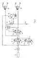
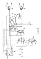
- the parking brake device has a first electrically controllable solenoid valve 1 and a second electrically controllable solenoid valve 2, at whose outputs a pneumatically controllable safety valve 3 is connected.
- the two solenoid valves 1 and 2 are connected via a check valve 4 with a Parking / trailer brake device of the vehicle connected via the compressed air can be supplied.
- this is more generally represented as a compressed air source, such as a Druck Kunststoffbeffleffleter 5.
- Both solenoid valves 1 and 2 are each brought by a spring 6 and 7 in a rest position. They are each so-called 3/2-way valves and by the spring 6 and 7 monostable.
- the pneumatically controllable safety valve 3 is brought by a spring 8 in a rest position.
- the safety valve 3 is also a 3/2-way valve. However, it is designed bistable by the nature of its interconnection.
- each of the rest positions are shown, in which the corresponding valves 1, 2 and 3 are deactivated, that is not energized, are.
- the first solenoid valve 1 has an inlet 9, an outlet 10 and a vent outlet 11 which is connected to atmospheric pressure.
- the second solenoid valve 2 has an input 12, an output 13 and a vent outlet 14. In the illustrated rest position, the solenoid valve 1 connects the input 9 to the output 10 and blocks the vent outlet 11, while in the activated position the input 9th shuts off and the output 10 connects to the vent outlet 11.
- the second solenoid valve 2 blocks in the illustrated rest position from the input 12 and connects the output 13 to the vent outlet 14. In the energized or activated position, the second solenoid valve 2 connects the input 12 to the output 13, while the vent outlet 14 is shut off ,
- the pneumatically-controlled safety valve 3 also has three ports, namely an input 15, an output 16 and another port 17.
- the input 15 is connected to the output 10 of the first solenoid valve 1.
- the output 16 is connected to an input of a select-low valve 18, while the other terminal 17 is connected to the output 13 of the second solenoid valve 2.
- a second input of the select-low valve 18 is connected to the input 15 of the safety valve 3.
- An output of the select-low valve 18 is with a pneumatic control input 3s of the pneumatically controllable safety valve 3 is connected.
- a second output of the select-low valve 18 is connected to an input of a select-high valve 19.
- a second input of the select high valve 19 is connected to a pneumatic line 20, which is a pneumatic control line from the brake pedal of the vehicle and which is acted upon by pressure of the service brake of the vehicle.
- the output of the select-high valve 19 is connected to a pneumatic control input 21 of a relay valve 22 whose output 23 is connected to a pressure chamber of a spring-loaded brake cylinder 23.
- the spring brake is released when said pressure chamber of the spring-loaded brake cylinder 23 is acted upon with compressed air.
- the parking brake is activated by the spring of the spring-loaded brake cylinder 23 when said pressure chamber is vented.
- the pneumatically controllable safety valve 3 blocks in the illustrated rest position the input 15 and connects the output 16 to the terminal 17. In the activated position of the safety valve 3, however, the input 15 is connected to the output 16 and the terminal 17 is shut off.
- the output 10 of the first solenoid valve 1 is still connected to a first trailer brake valve 24 and the output 16 of the safety valve 3 is connected to a second trailer brake valve 25.
- These are the trailer brake valves required for dual-line brake systems according to the European standard version (Trailer Modules).
- the select-low valve 18 is thus also between the two lines for the two trailer brake valves 24 and 25th
- the pneumatically controllable safety valve 3 may be a normal pneumatic valve. It can also be a pneumatically controllable servo valve. Finally, the safety valve 3 may also be electrically controllable, ie it may be a bistable electrically controllable solenoid valve, which is characterized by the in FIG. 5 dashed shown safety valve 3 is indicated. In this case is then its electrical control input 3b connected to electrical lines and not with a pneumatic output of the select-low valve 18th
- a supply input 26 of the relay valve 23 is connected via the check valve 4 directly to the compressed air supply 5.
- the device has two safe, stable states, namely the normal driving state and the state of the activated parking brake. In case of failure of the electrical supply immediately preceding the failure state is maintained stable.
- the arrangement also realizes a proportional braking in the driving state, a trailer test function in the parking state, a so-called anti-compounding function and the functions of switching from the park state to the driving state and vice versa from the driving state to the parking state.
- the so-called anti-compound function prevents overloading of the parking brake, if additionally the service brake is activated with activated parking brakes and thus service brake pressure could be superimposed on the spring brake pressure.
- the safety function is realized by the safety valve 3.
- This safety valve 3 is in the in Fig. 1 Parking position shown held by the spring 8.
- the connections 16 and 17 of the safety valve 3 are connected and vented via the second solenoid valve 2 to its vent outlet 14 out.
- atmospheric pressure is applied to the pneumatic control input 3s of the safety valve 3 via the select-low valve 18, so that the safety valve 3 is deactivated and brought into the illustrated position by the spring 8.
- In the parking position there is normally no pressure (service brake deactivated) on the line 20, so that atmospheric pressure also reaches the pneumatic control input 21 of the relay valve 22 via the select-high valve 19. This is so vented, so that the spring chamber the spring-loaded brake cylinder 23 is vented and thus the parking brake is applied or activated.
- the safety valve 3 With the parking brake deactivated, i. when driving, the safety valve 3 is turned on, i. activated.
- the input 15 is connected via the select-low valve 18 to the output 16 and via a feedback circuit formed by the select-low valve 18, the pressure from the compressed air supply 5 via the solenoid valve 1 to the input 15 and the output 16 of the valve 3 and thus via the select-low valve 18 to the control input 3s, so that the activated position of the valve 3 is kept stable pneumatically, as long as the two solenoid valves 1 and 2 remain in their illustrated deactivated position.
- the switching from the driving state to the parking brake is performed by the first solenoid valve 1. If this is activated, its input 9 is shut off and its output 10 is connected to the vent outlet 11. This reduces the pressure at the select-low valve 18. Once this pressure has reached a predetermined threshold, which is adjustable by the force of the spring 8, the safety valve 3 switches to the in FIG. 1 shown rest position back. The predetermined threshold is required to allow the system to differentiate between park brake and proportional brake switching.
- the relay valve 22 receives at its control input 21 also this low pressure. It is thereby brought into the venting position, whereby the spring chamber of the spring-loaded brake cylinder 23 is vented and thus the parking brake is activated by the spring.
- a proportional braking via the spring-loaded brake cylinder 23 can be achieved by rapid switching on and off of the first solenoid valve 1.
- the output 10 is also only briefly connected to the vent outlet 11 and thus the pressure at the select-low valve 18 is lowered slightly.
- the safety valve 3 still remains in its stable position.
- the relay valve 22 lowers the pressure at its output slightly, so that the pressure chamber of the spring-loaded brake cylinder 23 is slightly vented and thus the spring applies the parking brake slightly.
- the braking force is thus proportional to the duration of activation of the first solenoid valve 1. If the pressure is lowered by a longer activation of the first solenoid valve below a predetermined threshold, the parking brake is fully activated.
- the corresponding threshold value is again determined by the spring 8 of the safety valve 3.
- this spring 8 is correspondingly weak to dimension, so that a complete switching of the safety valve 3 takes place only at very low pressure at the control input 3s.
- the solenoid valves 1 and 2 are activated simultaneously.
- the pressure from the pressure medium source 5 to the second trailer module 25 is switched through, while the relay valve 22 and the first trailer module 24 are vented through the activated first solenoid valve 1 in conjunction with the select-low valve 18 , As a result, the parking brake on the trailer is released, which is required for the trailer test.
- the anti-compound function is pneumatically realized by the select high valve 19, which can solve the parking brake of the towing vehicle when brake pressure of the service brake via the line 20 and the select high valve 19 to the pneumatic control input 21 of the relay 22nd arrives.
- the service brake not shown, can be activated via the line 20. In other words, this ensures that the service brake has priority over the parking brake.
- the anti-compound function can also be achieved by quickly switching the second solenoid valve 2. Due to a relatively high hysteresis of the safety valve 3, the switching pressure level for the switch from parking to driving over the full release pressure of the spring chambers of the spring brake 23 can be adjusted. This function ensures that the safety valve 3 does not switch to the driving position during anti-compounding.
- FIG. 1 various modifications can be made.
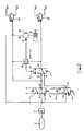
- a first modification is in FIG. 2 shown.
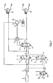
- FIG. 2 differs from the embodiment of FIG. 1 in that the select-high valve 19 is omitted.
- the pneumatic anti-compound function is not available.
- the anti-compounding function can be realized electronically by a control, not shown, in connection with the mentioned high hysteresis of the safety valve 3.
- the safety valve 3 can be replaced by a servo valve.
- a servo-valve has in principle the same function as the safety valve 3, but the position of the valve can be fixed with an electronic control against the pressure in the control chamber. This allows the system to realize a software controlled anti-compounding function by quickly turning the solenoid valve 2 on and off and holding the servo safety valve 3 in the park position by electronic control.
- the other functions work as described above.
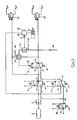
- the proportional braking and the anti-compound function are realized by rapid movements of the solenoid valves 1 and / or 2.
- the input 30 is connected to the vent outlet 11 of the first solenoid valve 1 and to the vent outlet 14 of the second solenoid valve and the outlet 31 is vented to the atmosphere.
- the input 30 and the output 31 are connected to each other.
- input 30 and output 31 are shut off from each other. With this valve 28, the system can be locked as soon as the desired pressure is reached. As a result, the number of cycles required by the solenoid valves 1 and 2 is substantially reduced.
- the solenoid valve 28 has no influence on the bistability of the system, this variant is also applicable to the systems described above, in which the safety valve 3 may have different configuration, namely as a pneumatically controlled valve, as a servo valve or as a bistable solenoid valve.
- FIG. 3 shows the system with select high valve 19 and FIG. 4 without select high valve. The remaining functions are otherwise unchanged.
- a further modification consists in the embodiments of the Figures 1 and 2 to replace the pneumatically-controlled safety valve 3 by a bistable solenoid valve 3, which is in Fig. 5 is shown.
- the pneumatic control line 3s is then replaced by an electrical line 3b, whereby the structure is easier.
- the bistable solenoid safety valve 3 the controller works more directly.
- FIG. 5 shows an embodiment of the invention, in which the safety valve 3 is a bistable electrically controlled solenoid valve.
- the three solenoid valves 1, 2 and 3 are connected with their electrical control terminals to an electronic controller 28.
- two pressure-voltage transformers 29 and 30 are provided, one of which is connected to the input 15 of the safety valve 3 and the other to the output 16 of the safety valve 3.
- Both pressure-voltage converters 29 and 30 transmit an electrical signal corresponding to the pressure to the controller 28.
- the two pressure-voltage converters 29 and 30 thus measure the input pressures at the select-low valve 18, whereupon the electronic controller 28 determines whether to switch the safety valve 3 or in one to hold his two stable positions.
- the two solenoid valves 1 and 2 can be operated by the driver via electrical switches 31 and 32, which are designed as buttons.
- the hysteresis necessary for the safety valve 3 can be determined electronically by the controller 28 by establishing suitable switching thresholds.
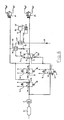
- FIG. 6 is different from that of FIG. 1 essentially in that the 3/2-way valve 1 is replaced by two 2/2-holding solenoid valves 1 a and 1 b.
- the pressure control is realized by a "flying" operation of the solenoid valve, which is not accurate enough in all cases and requires a high stability of the valve.
- the two 2/2 solenoid valves do not require "flying" operation of the valves, and pressure control can be more accurate.
- the safety valve 3 has in this embodiment, an additional pneumatic control input 3s2, which allows a more precise switching point for the parking position.
- the 2/2-Haltemagnetvenitle 1 a and 1 b and the safety valve 3 are connected as follows:
- the input 9 a of the valve 1 a is connected to the compressed air supply 5 and, as at FIG. 1
- its output 10a is connected to the input 9a and to the input 15 of the safety solenoid valve 3 and also to an input of the select-low valve 18.
- the Input 9a and the output 10a shut off.
- the 2/2-holding solenoid valve 1 b is connected with its input 9 b to the input 15 of the safety valve 3. Its output 10b is connected to atmosphere. In the illustrated rest position of FIG. 6 Input 9b and output 10b are shut off, while they are connected in the activated position of the valve 1 b with each other and thus stand on "venting position".
- the additional pneumatic control input 3s2 of the safety valve 3 is connected to the further connection 17 of the safety valve 3 and to the outlet 13 of the valve 2.
- FIG. 7 shows a modification, with the addition of a trailer braking function can be realized.
- this trailer braking function the driver can operate the brakes of the trailer independently of those of the towing vehicle to stabilize the vehicle in extreme driving situations. For example, a so-called stretch braking can be performed in which only the trailer but not the towing vehicle is braked.
- FIG. 7 shown modification is compared to FIG. 6 omitted the select-low valve and functionally replaced by a throttle point 35. Also, the second trailer brake valve 25 is omitted.
- the output 16 of the safety valve 3 is connected via a throttle point 35 with the pneumatic control input 3s of the safety valve 3. Further, the output 16 of the safety valve 3 is connected directly to a terminal of the select high-valve 19.
- the safety valve 3 has, as in the embodiment of Fig. 6 , two pneumatic control inputs 3s and 3s2, which act in opposite directions.
- the first (in Fig. 7 upper) pneumatic control input 3s is connected via the throttle point 35 to the output of the safety valve 3.
- the second pneumatic control input 3s2 is as at Fig. 6 , connected to the second input 17.
- the throttle point 35 has the effect that the pressure at the control input 3s lags in time the pressure at the output 16.
- FIG. 7 the trailer brake function and the parking brake function are realized by the following switching positions:
- the solenoid valve 1a If the solenoid valve 1a is in the holding position, the solenoid valve 1b is in the venting position and the solenoid valve 2 is in the venting position, the pressure at the pneumatic control input 3s of the safety valve 3 rises more slowly than at the lower pneumatic control input 3s2 due to the throttle point 35.
- the safety valve 3 is in the position shown and the relay valve 26 is pressurized at its pneumatic control input 21 via the select high valve 19 with pressure, so that the parking brake is released.
- the trailer brake valve 24 is vented via the solenoid valve 1b, which is in the venting position, and the service brake of the trailer is deactivated.
- the solenoid valve 2 If the solenoid valve 2 is deactivated, it goes into the in FIG. 7 Due to the orifice 35, the pressure at the upper pneumatic control input 3s of the safety valve 3 drops more slowly than at the lower pneumatic control input 3s2. As a result, the safety valve 3 switches through and connects the input 15 to the output 16. The safety valve 3 can then be controlled via the two valves 1a and 1b and thus control the relay valve 22, ie venting via the valve 1a and venting via the valve 1b ,
Description
- Die Erfindung bezieht sich auf eine Parkbremseinrichtung gemäß dem Oberbegriff des Patentanspruches 1.
- Eine derartige Parkbremseinrichtung ist aus der
DE 10 2005 058 799 A1 bekannt. Dort werden Federspeicherbremszylinder über ein Relaisventil angesteuert, das seinerseits über ein 3/2-Wege-Sicherheitsventil ansteuerbar ist. Dieses Sicherheitsventil verbindet wahlweise seinen Ausgang mit einer Druckluftquelle oder Atmosphärendruck. Zweck dieser Parkbremseinrichtung ist es, dem Fahrer zu ermöglichen, bei Ausfall der elektrischen Stromversorgung durch Betätigen der Betriebsbremse die Parkbremse zu aktivieren. - Parkbremsen (auch Feststellbremse genannt) von Nutzfahrzeugen einschließlich Anhängern sowie Schienenfahrzeugen sind heute regelmäßig mit Federspeicherbremszylinder ausgestattet, die in Lösestellung einen Federkompressionsraum mit Druckluft beaufschlagen und dadurch die Feder gespannt halten, während zum Parkbremsen der Federkompressionsraum entlüftet, d.h. mit Atmosphärendruck verbunden wird, so dass der Bremszylinder unter Wirkung der Feder eine Bremskraft erzeugt (vgl. Bosch, Kraftfahrtechnisches Taschenbuch, 22. Auflage, Düsseldorf, 1995, S. 648).
- Es sind sowohl rein pneumatisch betriebene Parkbremsen bekannt, die mit vom Fahrer zu betätigenden, meist bistabilen Parkbremsventilen betrieben werden, als auch elektro-pneumatische Anlagen mit einem bistabilen elektromechanischen Ventil, das durch ein elektromechanisches bistabiles Magnetventil gesteuert wird. Beide Ventilstellungen für "Parkbremse" und "Lösen" müssen dabei "stabil" sein, d.h. ohne Einwirkung einer Person in der jeweils gewählten Stellung bleiben. Dies gilt auch für einen Ausfall einer elektrischen Stromversorgung für die Magnetventile.
- Aufgabe der Erfindung ist es, die Parkbremseinrichtung der eingangs genannten Art dahingehend weiter zu verbessern, dass mit handelsüblichen und robusten Bauelementen alle Anforderungen an eine Parkbremseinrichtung sicher erfüllt werden. Zu diesen Anforderungen gehören insbesondere:
- Stabilität des Systems auch bei Ausfall einer elektrischen Stromversorgung,
- sicheres und einfaches Umschalten zwischen den Betriebsarten
- Notbremseinrichtung, d.h. bei Ausfall der Betriebsbremse soll die Federspeicherbremse mit steuerbarer Bremskraft einsetzbar sein;
- es soll ein Test einer Anhängerbremse auch bei aktivierter Parkbremse eines Zugfahrzeuges möglich sein ("Trailer-Test");
- optional soll auch mit einfachen Mitteln eine Anti-Compound-Funktion realisierbar sein, d.h. es soll vermieden werden, dass die Parkbremse übermäßig beansprucht wird, wenn bei aktivierter Parkbremse gleichzeitig die Betriebsbremse wirkt.
- Die oben genannte Aufgabe wird durch die im Patentanspruch 1 angegebenen Merkmale gelöst. Vorteilhafte Ausgestaltungen und Weiterbildungen der Erfindung sind den Unteransprüchen zu entnehmen.
- Bei der Erfindung ist das die Stabilität gewährleistende Element ein normales handelsübliches Ventil, wie z.B. ein pneumatisch gesteuertes Ventil, ein Servo-Ventil oder auch ein elektrisch gesteuertes Magnetventil (im folgenden "Sicherheitsventil" genannt). Das Sicherheitsventil ist über zwei Magnetventile ansteuerbar. Es steuert seinerseits über ein Select-Low-Ventil und optional zusätzlich noch über ein Select-High-Ventil das Relaisventil an, welches die Federspeicherbremse steuert. Das Sicherheitsventil ist von seiner Bauart ein monostabiles Ventil, das in einem "Rückkopplungszweig" zwischen seinem Ausgang und einem Steuereingang ein Select-Low-Ventil geschaltet hat, dem der Eingangsdruck des Sicherheitsventils zugeführt wird. Der geringere dieser beiden Drücken wird durch das Select-Low-Ventil dem Steuereingang des Sicherheitsventils zugeführt. Dadurch wird die Bistabilität erreicht. Gleichzeitig führt das Select-Low-Ventil den ausgewählten Druck auch dem Steuereingang des Relaisventils zu, welches die Federspeicherbremse steuert.
- Nach einer Weiterbildung der Erfindung wird eine Anti-Compound-Funktion dadurch erreicht, dass zwischen das Select-Low-Ventil und den pneumatischen Steuereingang des Relaisventils noch ein Select-High-Ventil geschaltet wird, dessen einem Eingang der Ausgang des Select-Low-Ventils und dessen anderem Eingang der Druck der Betriebsbremse zugeführt wird. Das Select-High-Ventil wählt den höheren von beiden Drücken aus und führt diesen dem Steuereingang des Relaisventils zu. Damit ist sichergestellt, dass der Steuereingang des Relaisventils stets nur mit einem eindeutig definierten Druck beaufschlagt ist und dass die Betriebsbremse Vorrang vor der Parkbremse hat.
- Die Erfindung realisiert somit die geforderten Sicherheitsfunktionen und Betriebsfunktionen einer Parkbremseinrichtung, nämlich Parken, Lösen der Parkbremse, Hilfsbremse, Anhängertest und Anti-Compound. Die Erfindung ist ausführbar mit zwei 3/2 monostabilen Magnetventilen und einem bistabilen 3/2 Magnetventil (Sicherheitsventil) und einem Select-Low-Ventil oder mit zwei 3/2 monostabilen Magnetventilen, einem 3/2 Servo-Magnetventil (Sicherheitsventil) und einem Select-Low-Ventil oder mit zwei 3/2 monostabilen Magnetventilen und einem 3/2 pneumatischem Ventil (Sicherheitsventil) und einem Select-Low-Ventil. Die Erfindung realisiert optional eine pneumatische Anti-Compound-Funktion durch ein Select-High-Ventil und eine pneumatische Verbindung mit der Betriebsbremse des Fahrzeuges oder auch eine durch Software in einem Steuergerät realisierte Anti-Compound-Funktion.
- Die Erfindung verwendet eine auswählbare Anhängerparkbremsfunktion und erfüllt damit auch die Anforderungen unterschiedlicher Hersteller für unterschiedliche Anhängerbremssysteme.
- Die Erfindung liefert auch den Steuerdruck für ein Anhängerbremsmodul (TCM; Trailer Control Module) über den Ausgang des bistabilen Ventils für die Anhängerbremsen, dessen Betriebsbremse aktiviert sein kann, wenn das Zugfahrzeug in der Parkposition ist.
- Die Erfindung wählt weiter den Steuerdruck für das Relaisventil der Federspeicherbremse des Zugfahrzeuges von zwei TCM-Steuerleitungen über ein Select-Low-Ventil. Mit der Erfindung kann auch eine von Hand gesteuerte Proportionalbremsung mittels der Parkbremse durchgeführt werden, indem ein Magnetventil kurzfristig bzw. schnell betätigt wird, wobei ein Sensorsignal eines Drucksensors verwendet werden kann, der den Ausgangsdruck des Relaisventils mißt. Alternativ kann der Druck auch proportional unter Verwendung des genannten Magnetventils und eines zusätzlichen Haltemagnetventils gesteuert werden.
- Weiter kann der gewünschte Druck einer Software basierten Anti-Compound-Funktion durch schnelles Umschalten eines zweiten Magnetventils gesteuert werden oder alternativ durch das genannte zweite Magnetventil und ein Haltemagnetventil.
- Im folgenden wird die Erfindung anhand von Ausführungsbeispielen im Zusammenhang mit der Zeichnung ausführlicher erläutert. Es zeigt:
- Figur 1
- ein erstes Ausführungsbeispiel der Parkbremseinrichtung nach der Erfindung;
- Figur 2
- ein vereinfachtes zweites Ausführungsbeispiel der Erfindung;
- Figur 3
- ein drittes Ausführungsbeispiel der Erfindung;
- Figur 4
- ein viertes Ausführungsbeispiel der Erfindung;
- Figur 5
- ein fünftes Ausführungsbeispiel der Erfindung;
- Figur 6
- ein sechstes Ausführungsbeispiel der Erfindung; und
- Figur 7
- ein siebtes Ausführungsbeispiel der Erfindung.
- Zunächst wird auf
Figur 1 Bezug genommen. - Die Parkbremseinrichtung hat ein erstes elektrisch steuerbares Magnetventil 1 und ein zweites elektrisch steuerbares Magnetventil 2, an deren Ausgängen ein pneumatisch steuerbares Sicherheitsventil 3 angeschlossen ist. Die beiden Magnetventile 1 und 2 sind über ein Rückschlagventil 4 mit einer Park-/Anhängerbremseinrichtung des Fahrzeuges verbunden, über die Druckluft zuführbar ist. In den Zeichnungen ist dies allgemeiner als Druckluftquelle, wie z.B. einen Druckluftbehätter 5, dargestellt. Beide Magnetventile 1 und 2 werden jeweils durch eine Feder 6 bzw. 7 in eine Ruhelage gebracht. Sie sind jeweils sogenannte 3/2-Wegeventile und durch die Feder 6 bzw. 7 monostabil. Ebenso wird das pneumatisch-steuerbare Sicherheitsventil 3 durch eine Feder 8 in eine Ruhelage gebracht. Das Sicherheitsventil 3 ist ebenfalls ein 3/2-Wegeventil. Es ist jedoch durch die Art seiner Verschaltung bistabil ausgelegt.
- In
Figur 1 sind jeweils die Ruhelagen dargestellt, bei denen die entsprechenden Ventile 1, 2 bzw. 3 deaktiviert, d.h. nicht erregt, sind. Das erste Magnetventil 1 hat einen Eingang 9, einen Ausgang 10 und einen Entlüftungsausgang 11, der mit Atmosphärendruck verbunden ist. In ähnlicher Weise hat das zweite Magnetventil 2 einen Eingang 12, einen Ausgang 13 und einen Entlüftungsausgang 14. In der dargestellten Ruhelage verbindet das Magnetventil 1 den Eingang 9 mit dem Ausgang 10 und sperrt den Entlüftungsausgang 11, während es in der aktivierten Lage den Eingang 9 absperrt und den Ausgang 10 mit dem Entlüftungsausgang 11 verbindet. - Das zweite Magnetventil 2 sperrt in der dargestellten Ruhestellung den Eingang 12 ab und verbindet den Ausgang 13 mit dem Entlüftungsausgang 14. In der erregten bzw. aktivierten Position verbindet das zweite Magnetventil 2 dagegen den Eingang 12 mit dem Ausgang 13, während der Entlüftungsausgang 14 abgesperrt ist.
- Das pneumatisch-gesteuerte Sicherheitsventil 3 hat ebenfalls drei Anschlüsse und zwar einen Eingang 15, einen Ausgang 16 und einen weiteren Anschluß 17. Der Eingang 15 ist mit dem Ausgang 10 des ersten Magnetventils 1 verbunden. Der Ausgang 16 ist mit einem Eingang eines Select-Low-Ventils 18 verbunden, während der weitere Anschluß 17 mit dem Ausgang 13 des zweiten Magnetventils 2 verbunden ist.
- Ein zweiter Eingang des Select-Low-Ventils 18 ist mit dem Eingang 15 des Sicherheitsventils 3 verbunden. Ein Ausgang des Select-Low-Ventils 18 ist mit einem pneumatischen Steuereingang 3s des pneumatisch steuerbaren Sicherheitsventils 3 verbunden.
- Ein zweiter Ausgang des Select-Low-Ventils 18 ist mit einem Eingang eines Select-High-Ventils 19 verbunden. Ein zweiter Eingang des Select-High-Ventils 19 ist mit einer pneumatischen Leitung 20 verbunden, die eine pneumatische Steuerleitung vom Bremspedal des Fahrzeuges ist und die mit Druck der Betriebsbremse des Fahrzeuges beaufschlagt ist.
- Der Ausgang des Select-High-Ventils 19 ist mit einem pneumatischen Steuereingang 21 eines Relaisventils 22 verbunden, dessen Ausgang 23 mit einer Druckkammer eines Federspeicher-Bremszylinders 23 verbunden ist. Die Federspeicherbremse ist dann gelöst, wenn die genannte Druckkammer des Federspeicher-Bremszylinders 23 mit Druckluft beaufschlagt ist. Umgekehrt ist die Parkbremse durch die Feder des Federspeicher-Bremszylinders 23 aktiviert, wenn die genannte Druckkammer entlüftet ist.
- Das pneumatisch steuerbare Sicherheitsventil 3 sperrt in der abgebildeten Ruhestellung den Eingang 15 ab und verbindet den Ausgang 16 mit dem Anschluß 17. In der aktivierten Stellung des Sicherheitsventils 3 ist dagegen der Eingang 15 mit dem Ausgang 16 verbunden und der Anschluß 17 ist abgesperrt.
- Schließlich ist der Ausgang 10 des ersten Magnetventils 1 noch mit einem ersten Anhängerbremsventil 24 verbunden und der Ausgang 16 des Sicherheitsventils 3 ist mit einem zweiten Anhängerbremsventil 25 verbunden. Es handelt sich dabei um die bei Zweileitungsbremsanlagen gemäß europäischer Standardausführung notwendigen Anhängerbremsventile (Trailer Module). Das Select-Low-Ventil 18 liegt somit auch zwischen den beiden Leitungen für die beiden Anhängerbremsventile 24 und 25.
- Das pneumatisch steuerbare Sicherheitsventil 3 kann ein normales Pneumatikventil sein. Es kann auch ein pneumatisch steuerbares Servo-Ventil sein. Schließlich kann das Sicherheitsventil 3 auch elektrisch steuerbar sein, d.h. es kann ein bistabiles elektrisch steuerbares Magnetventil sein, was durch das in
Figur 5 gestrichelt dargestellte Sicherheitsventil 3 angedeutet ist. In diesem Falle ist dann sein elektrischer Steuereingang 3b mit elektrischen Leitungen verbunden und nicht mit einem pneumatischen Ausgang des Select-Low-Ventils 18. - Ein Versorgungseingang 26 des Relaisventils 23 ist über das Rückschlagventil 4 direkt mit der Druckluftversorgung 5 verbunden.
- Im folgenden wird die Wirkungsweise der Parkbremseinrichtung der
Figur 1 erläutert. Die Einrichtung hat zwei sichere, stabile Zustände, nämlich den normalen Fahrtzustand und den Zustand der aktivierten Parkbremse. Bei Ausfall der elektrischen Versorgung wird der unmittelbar dem Ausfall vorhergehende Zustand stabil beibehalten. - Über diese Sicherheitsfunktionen hinaus realisiert die Anordnung auch eine proportionale Bremsung im Fahrzustand, eine Anhängertestfunktion beim Parkzustand, eine sogenannte Anti-Compound-Funktion und die Funktionen des Umschaltens vom Parkzustand in den Fahrzustand und umgekehrt vom Fahrzustand in den Parkzustand. Die sogenannte Anti-Compound-Funktion verhindert eine Überlastung der Parkbremse, wenn bei aktivierter Parkbremsen zusätzlich die Betriebsbremse betätigt wird und somit Betriebsbremsdruck dem Federspeicher-Bremsdruck überlagert werden könnte.
- Im folgenden werden die einzelnen Funktionen näher erläutert:
- Die Sicherheitsfunktion wird durch das Sicherheitsventil 3 realisiert. Dieses Sicherheitsventil 3 wird in der in
Fig. 1 dargestellten Parkstellung durch die Feder 8 gehalten. Die Anschlüsse 16 und 17 des Sicherheitsventils 3 sind verbunden und über das zweite Magnetventil 2 zu dessen Entlüftungsausgang 14 hin entlüftet. Über das Select-Low-Ventil 18 wird somit Atmosphärendruck an den pneumatischen Steuereingang 3s des Sicherheitsventils 3 gelegt, so dass das Sicherheitsventil 3 deaktiviert und durch die Feder 8 in die dargestellte Stellung gebracht ist. In der Parkposition ist auf der Leitung 20 normalerweise kein Druck (Betriebsbremse deaktiviert), so dass über das Select-High-Ventil 19 ebenfalls Atmosphärendruck an den pneumatischen Steuereingang 21 des Relaisventils 22 gelangt. Dieses ist damit entlüftet, so dass auch die Federkammer des Federspeicher-Bremszylinders 23 entlüftet ist und damit die Parkbremse angelegt bzw. aktiviert ist. - Bei deaktivierter Parkbremse, d.h. beim Fahrtzustand, ist das Sicherheitsventil 3 durchgeschaltet, d.h. aktiviert. Der Eingang 15 ist über das Select-Low-Ventil 18 mit dem Ausgang 16 verbunden und über einen durch das Select-Low-Ventil 18 gebildeten Rückkopplungskreis gelangt der Druck von der Druckluftversorgung 5 über das Magnetventil 1 zum Eingang 15 und zum Ausgang 16 des Ventils 3 und damit über das Select-Low-Ventil 18 zum Steuereingang 3s, so dass auch die aktivierte Stellung des Ventils 3 stabil pneumatisch gehalten ist, solange die beiden Magnetventile 1 und 2 in ihrer dargestellten deaktivierten Position bleiben. Über das aktivierte Sicherheitsventil 3 gelangt Druck von der Druckmittelquelle 5 auch zum Steuereingang 21 des Relaisventils 22, welches durchschaltet und damit die Federkammer des Federspeicher-Bremszylinders 23 mit Druck beaufschlagt und damit die Federspeicher-Bremse löst. Somit ist die Sicherheitsfunktion realisiert, d.h. beide beschriebenen Betriebszustände sind jeweils für sich stabil, unabhängig von dem Zustand der Stromversorgung der Magnetventile 1 und 2.
- Durch Betätigen des zweiten Magnetventils 2 wird dessen Eingang 12 mit dem Ausgang 13 verbunden. Damit gelangt Druckluft aus der Druckmittelquelle 5 zum Anschluß 17 des Sicherheitsventils 3 und von dessen Ausgang 16 zum Select-Low-Ventil 18, an dessen anderen Eingang ebenfalls der Druck der Druckmittelquelle 5 über das durchgeschaltete erste Magnetventil 1 liegt. Damit gelangt der hohe Druck zum Steuereingang 3s des Sicherheitsventils 3, das durchschaltet und den Eingang 15 mit dem Ausgang 16 verbindet. Über das Select-High-Ventil 19 gelangt dieser Druck an den Steuereingang 21 des Relaisventils 22, das durchschaltet und somit den Druck von seinem Eingang 26 zur Federkammer des Federspeicher-Bremszylinders 23 gelangen läßt, so dass die Federspeicher-Bremse gelöst wird. Das Sicherheitsventil 3 gelangt in die zweite, durch Druck gehaltene stabile Position.
- Das Umschalten vom Fahrzustand zur Parkbremse erfolgt durch das erste Magnetventil 1. Wird dieses aktiviert, so wird sein Eingang 9 abgesperrt und sein Ausgang 10 mit dem Entlüftungsausgang 11 verbunden. Damit sinkt der Druck am Select-Low-Ventil 18 ab. Sobald dieser Druck einen vorgegebenen Schwellwert erreicht hat, der durch die Kraft der Feder 8 einstellbar ist, schaltet das Sicherheitsventil 3 in die in
Figur 1 gezeigte Ruhestellung zurück. Der vorgegebene Schwellwert ist dazu erforderlich, dem System zu ermöglichen, zwischen Umschaltung auf Parkbremse und proportionalem Bremsen zu unterscheiden. Das Relaisventil 22 erhält an seinem Steuereingang 21 ebenfalls diesen niedrigen Druck. Es wird dadurch in die Entlüftungsstellung gebracht, wodurch die Federkammer des Federspeicher-Bremszylinders 23 entlüftet und damit die Parkbremse durch die Feder aktiviert wird. - Ist die Anordnung im Fahrzustand, so kann ein proportionales Bremsen über den Federspeicher-Bremszylinder 23 durch schnelles Ein- und Ausschalten des ersten Magnetventils 1 erreicht werden. Durch dieses kurzfristige Umschalten wird der Ausgang 10 auch nur kurzzeitig mit dem Entlüftungsausgang 11 verbunden und damit der Druck am Select-Low-Ventil 18 geringfügig abgesenkt. Das Sicherheitsventil 3 bleibt dabei noch in seiner stabilen Position. Das Relaisventil 22 senkt jedoch den Druck an seinem Ausgang geringfügig ab, so dass die Druckkammer des Federspeicher-Bremszylinders 23 geringfügig entlüftet wird und damit die Feder die Parkbremse geringfügig anlegt. Die Bremskraft ist damit proportional der Zeitdauer der Aktivierung des ersten Magnetventils 1. Wird der Druck durch längeres Aktivieren des ersten Magnetventils unter einen vorgegebenen Schwellwert abgesenkt, so wird die Parkbremse vollständig aktiviert.
- Der entsprechende Schwellwert wird wiederum durch die Feder 8 des Sicherheitsventils 3 bestimmt. Um die proportionale Bremsfunktion über einen möglichst großen Bereich aufrechterhalten zu können, ist diese Feder 8 entsprechend schwach zu dimensionieren, damit ein vollständiges Umschalten des Sicherheitsventils 3 erst bei sehr niedrigem Druck an dessen Steuereingang 3s erfolgt.
- Für die vorgeschriebene Trailer-Test-Funktion werden die Magnetventile 1 und 2 gleichzeitig aktiviert. Durch das zweite Magnetventil 2 wird der Druck von der Druckmittelquelle 5 zu dem zweiten Trailer-Modul 25 durchgeschaltet, während durch das aktivierte erste Magnetventil 1 in Verbindung mit dem Select-Low-Ventil 18 das Relaisventil 22 und das erste Trailer-Modul 24 entlüftet werden. Im Ergebnis wird die Parkbremse am Trailer gelöst, was für den Trailer-Test erforderlich ist.
- Die Anti-Compound-Funktion wird pneumatisch durch das Select-High-Ventil 19 realisiert, das die Parkbremse des Zugfahrzeuges lösen kann, wenn Bremsdruck der Betriebsbremse über die Leitung 20 und das Select-High-Ventil 19 an den pneumatischen Steuereingang 21 des Relais 22 gelangt. Gleichzeitig kann über die Leitung 20 die nicht dargestellte Betriebsbremse aktiviert werden. Mit anderen Worten wird hierdurch erreicht, dass die Betriebsbremse Vorrang vor der Parkbremse hat.
- Bei elektronischer Steuerung kann die Anti-Compound-Funktion auch durch schnelles Schalten des zweiten Magnetventils 2 erreicht werden. Aufgrund einer relativ hohen Hysterese des Sicherheitsventils 3 kann der Schaltdruckpegel für die Umschaltung von Parken auf Fahren über den vollen Lösedruck der Federkammern der Federspeicher-Bremse 23 eingestellt werden. Diese Funktion stellt sicher, dass das Sicherheitsventil 3 während eines Anti-Compound nicht in die Fahrtstellung umschaltet.
- Dem Fachmann ist klar, dass an
Figur 1 verschiedene Modifikationen vorgenommen werden können. Eine erste Modifikation ist inFigur 2 gezeigt.Figur 2 unterscheidet sich vom Ausführungsbeispiel derFigur 1 dadurch, dass das Select-High-Ventil 19 fortgelassen ist. Dies hat zur Folge, dass die pneumatische Anti-Compound-Funktion nicht zur Verfügung steht. Bei diesem Ausführungsbeispiel kann jedoch die Anti-Compound-Funktion elektronisch durch eine nicht dargestellte Steuerung realisiert werden in Verbindung mit der erwähnten hohen Hysterese des Sicherheitsventils 3. - Bei beiden Ausführungsbeispielen der
Figuren 1 und2 kann das Sicherheitsventil 3 durch ein Servo-Ventil ersetzt werden. Ein solches Servo-Ventil hat im Prinzip dieselbe Funktion wie das Sicherheitsventil 3, jedoch kann die Position des Ventils mit einer elektronischen Steuerung gegen den Druck in der Steuerkammer fixiert werden. Dies erlaubt dem System, eine Software gesteuerte Anti-Compound-Funktion zu realisieren, indem man das Magnetventil 2 schnell ein - und ausschaltet und das Servo-Sicherheitsventil 3 durch eine elektronische Steuerung in der Parkposition hält. Die weiteren Funktionen arbeiten wie oben beschrieben. - Bei den bisher beschriebenen Ausführungsbeispielen sind die Proportional-Bremsung und die Anti-Compound-Funktion durch schnelle Bewegungen der Magnetventile 1 und/oder 2 realisiert.
- Zur Verlängerung der Lebensdauer von Magnetventilen, die je nach Bauart nur eine begrenzte Schaltzykluszeit haben, kann nach einer Weiterbildung der Erfindung, die in den
Figuren 3 und4 gezeigt ist, noch ein zusätzliches Haltemagnetventil 28 vorgesehen sein, dessen Eingang 30 mit dem Entlüftungsausgang 11 des ersten Magnetventils 1 und mit dem Entlüftungsausgang 14 des zweiten Magnetventils verbunden ist und dessen Ausgang 31 zur Atmosphäre hin entlüftet ist. In der dargestellten Ruhestellung sind der Eingang 30 und der Ausgang 31 miteinander verbunden. In der aktivierten Stellung sind Eingang 30 und Ausgang 31 gegeneinander abgesperrt. Mit diesem Ventil 28 kann das System verriegelt werden, sobald der gewünschte Druck erreicht ist. Dadurch wird die Anzahl der von den Magnetventilen 1 und 2 benötigten Zyklen wesentlich reduziert. Da das Magnetventil 28 keinen Einfluß auf die Bistabilität des Systems hat, ist diese Variante auch für die oben beschriebenen Systeme anwendbar, bei der das Sicherheitsventil 3 unterschiedliche Konfiguration haben kann, nämlich als pneumatisch gesteuertes Ventil, als Servo-Ventil oder als bistabiles Elektromagnetventil. - Auch diese Variante ist mit und ohne Select-High-Ventil 19 möglich.
Figur 3 zeigt das System mit Select-High-Ventil 19 undFigur 4 ohne Select-High-Ventil. Die übrigen Funktionen sind ansonsten unverändert. - Eine weitere Modifikation besteht darin, in den Ausführungsbeispielen der
Figuren 1 und 2 das pneumatisch-gesteuerte Sicherheitsventil 3 durch ein bistabiles Magnetventil 3 zu ersetzen, was inFig. 5 dargestellt ist. Die pneumatische Steuerleitung 3s wird dann durch eine elektrische Leitung 3b ersetzt, wodurch der Aufbau einfacher wird. Durch das bistabile Elektromagnet-Sicherheitsventil 3 arbeitet die Steuerung direkter. -
Figur 5 zeigt ein Ausführungsbeispiel der Erfindung, bei dem das Sicherheitsventil 3 ein bistabiles elektrisch gesteuertes Magnetventil ist. Die drei Magnetventile 1, 2 und 3 sind mit ihren elektrischen Steueranschlüssen mit einer elektronischen Steuerung 28 verbunden. Weiter sind zwei Druckspannungswandler 29 und 30 vorgesehen, von denen der eine an den Eingang 15 des Sicherheitsventils 3 und der andere an den Ausgang 16 des Sicherheitsventils 3 angeschlossen ist. Beide Druckspannungswandler 29 und 30 übermitteln ein dem Druck entsprechendes elektrisches Signal an die Steuerung 28. Die beiden Druckspannungswandler 29 und 30 messen damit die Eingangsdrücke am Select-Low-Ventil 18, worauf die elektronische Steuerung 28 ermittelt, ob das Sicherheitsventil 3 umzuschalten oder in einer seiner beiden stabilen Stellungen zu halten ist. - Anstelle der zwei Druckspannungswandler 29 und 30 kann auch nur ein einziger Druckspannungswandler 33 vorgesehen sein, der an den pneumatischen Steueranschluß 21 des Relaisventils 22 angeschlossen ist. Der dort gemessene Druck wird als elektrisches Signal der Steuerung 28 zugeführt, die dann das Sicherheitsventil 3 umschaltet oder in einer seiner beiden stabilen Stellungen hält.
- Die beiden Magnetventile 1 und 2 können vom Fahrer über elektrische Schalter 31 bzw. 32, die als Taster ausgebildet sind, betätigt werden.
- Die für das Sicherheitsventil 3 notwendige Hysterese kann auf elektronischem Wege durch die Steuerung 28 durch Festlegung geeigneter Schaltschwellen festgelegt werden.
- Ansonsten arbeitet die Einrichtung der
Figur 5 analog den vorhergehenden Ausführungsbeispielen, wobei darauf hingewiesen wird, dass auch beim Ausführungsbeispiel derFigur 5 das Select-High-Ventil 19 fortgelassen werden kann, falls die Anti-Compound-Funktion nicht benötigt wird. - Das Ausführungsbeispiel der
Figur 6 unterscheidet sich von dem derFigur 1 im wesentlichen dadurch, dass das 3/2-Wegeventil 1 durch zwei 2/2-Haltemagnetventile 1a und 1b ersetzt ist. Bei dem Ventil 1 derFigur 1 wird die Drucksteuerung durch einen "fliegenden" Betrieb des Magnetventils realisiert, was nicht in allen Fällen genau genug ist und eine hohe Standfestigkeit des Ventils erfordert. - Bei dem Ausführungsbeispiel der
Figur 6 mit den zwei 2/2-Haltemagnetventilen ist kein "fliegender" Betrieb der Ventile erforderlich und die Drucksteuerung kann präziser erfolgen. Das Sicherheitsventil 3 hat bei diesem Ausführungsbeispiel einen zusätzlichen pneumatischen Steuereingang 3s2, was einen präziseren Schaltpunkt für die Parkposition gestattet. - Die 2/2-Haltemagnetvenitle 1a und 1b und das Sicherheitsventil 3 sind wie folgt verschaltet: Der Eingang 9a des Ventils 1a ist mit der Druckluftversorgung 5 verbunden und, wie bei
Figur 1 , mit dem Eingang 12 des Magnetventils 2. Sein Ausgang 10a ist im dargestellten Ruhezustand mit dem Eingang 9a verbunden und mit dem Eingang 15 des Sicherheitsmagnetventils 3 und auch mit einem Eingang des Select-Low-Ventils 18. Im aktivierten Zustand des Ventils 1a sind der Eingang 9a und der Ausgang 10a abgesperrt. - Das 2/2-Haltemagnetventil 1b ist mit seinem Eingang 9b mit dem Eingang 15 des Sicherheitsventils 3 verbunden. Sein Ausgang 10b ist mit Atmosphäre verbunden. In der dargestellten Ruhestellung der
Figur 6 sind Eingang 9b und Ausgang 10b abgesperrt, während sie in der aktivierten Stellung des Ventils 1 b miteinander verbunden sind und damit auf "Entlüftungsstellung" stehen. - Der zusätzliche pneumatische Steuereingang 3s2 des Sicherheitsventils 3 ist mit dem weiteren Anschluß 17 des Sichefieitsventils 3 und mit dem Ausgang 13 des Ventils 2 verbunden.
- Durch entsprechende Ansteuerung der Magnetventile 1a, 1b, 2 und 3 können die oben im Zusammenhang mit
Figur 1 beschriebenen Funktionen ebenfalls realisiert werden. -
Figur 7 zeigt eine Modifikation, mit der zusätzlich eine Anhängerbremsfunktion realisiert werden kann. Mit dieser Anhängerbremsfunktion kann der Fahrer die Bremsen des Anhängers unabhängig von denen des Zugfahrzeuges betätigen, um in extremen Fahrsituationen den Fahrzeugverbund zu stabilisieren. Beispielsweise kann eine sogenannte Streckbremsung durchgeführt werden, bei der nur der Anhänger aber nicht das Zugfahrzeug gebremst wird. - Bei der in
Figur 7 dargestellten Modifikation ist im Vergleich zuFigur 6 das Select-Low-Ventil fortgelassen und funktionell durch eine Drosselstelle 35 ersetzt. Auch ist das zweite Anhängerbremsventil 25 fortgelassen. Der Ausgang 16 des Sicherheitsventils 3 ist über eine Drosselstelle 35 mit dem pneumatischen Steuereingang 3s des Sicherheitsventils 3 verbunden. Weiter ist der Ausgang 16 des Sicherheitsventils 3 direkt mit einem Anschluß des Select-High-Ventils 19 verbunden. Das Sicherheitsventil 3 hat, wie bei dem Ausführungsbeispiel derFig. 6 , zwei pneumatische Steuereingänge 3s und 3s2, die entgegengesetzt wirken. - Der erste (in
Fig. 7 obere) pneumatische Steuereingang 3s ist über die Drosselstelle 35 mit dem Ausgang des Sicherheitsventils 3 verbunden. Der zweite pneumatische Steuereingang 3s2 ist, wie beiFig. 6 , mit dem zweiten Eingang 17 verbunden. Die Drosselstelle 35 hat die Wirkung, dass der Druck am Steuereingang 3s zeitlich dem Druck am Ausgang 16 nacheilt. - Bei dieser Anordnung der
Figur 7 werden die Anhängerbremsfunktion und die Parkbremsfunktion durch folgende Schaltstellungen realisiert: - Sind das Magnetventil 1a in Halteposition, das Magnetventil 1b in Entlüftungsposition und das Magnetventil 2 in Belüftungsstellung, so steigt aufgrund der Drosselstelle 35 der Druck am pneumatischen Steuereingang 3s des Sicherheitsventils 3 langsamer an als am unteren pneumatischen Steuereingang 3s2. Damit geht das Sicherheitsventil 3 in die dargestellte Stellung und das Relaisventil 26 wird an seinem pneumatischen Steuereingang 21 über das Select-High-Ventil 19 mit Druck beaufschlagt, so dass die Parkbremse gelöst ist. Über das in Entlüftungsstellung stehende Magnetventil 1b wird das Anhängerbremsventil 24 entlüftet und die Betriebsbremse des Anhängers ist deaktiviert.
- Wird das Magnetventil 2 deaktiviert, so geht es in die in
Figur 7 dargestellte Ruhestellung und entlüftet den Eingang 17 und den zweiten Steuereingang 17 des Sicherheitsventils 3. Aufgrund der Drosselstelle 35 fällt der Druck am oberen pneumatischen Steuereingang 3s des Sicherheitsventils 3 langsamer ab als an dem unteren pneumatischen Steuereingang 3s2. Dadurch schaltet das Sicherheitsventil 3 durch und verbindet den Eingang 15 mit dem Ausgang 16. Das Sicherheitsventil 3 kann dann über die beiden Ventile 1a und 1 b gesteuert werden und damit das Relaisventil 22 steuern, d.h. belüften über das Ventil 1a und entlüften über das Ventil 1b.
Claims (10)
- Parkbremseinrichtung für Kraftfahrzeuge mit einem von einem Relaisventil (22) ansteuerbaren Federspeicher-Bremszylinder (23), wobei das Relaisventil (22) über ein als 3/2-Wegeventil ausgebildetes Sicherheitsventil (3) ansteuerbar ist, dessen Ausgang (16) wahlweise mit einem von zwei Eingängen (15, 17) verbindbar ist, wobei die Eingänge (15, 17) des Sicherheitsventils (3) über ein erstes oder ein zweites Magnetventil (1, 2), wahlweise mit einer Druckmittelquelle (5) oder Atmosphärendruck, verbindbar sind, dadurch gekennzeichnet, dass ein Select-Low-Ventil (18) mit dem einen Eingang (15) und dem Ausgang (16) des Sicherheitsventils (3) verbunden ist und ein Ausgang des Select-Low-Ventils (18) mit einem Steuereingang (21) des Relaisventils (22) verbunden ist.
- Parkbremseinrichtung nach Anspruch 1, dadurch gekennzeichnet, dass das Sicherheitsventil (3) ein pneumatisch steuerbares Ventil ist, dessen Steuereingang (3s) mit einem Ausgang des Select-Low-Ventils (18) verbunden ist.
- Parkbremseinrichtung nach Anspruch 1 oder 2, dadurch gekennzeichnet, dass zwischen das Select-Low-Ventil (18) und den Steuereingang (21) des Relaisventils (22) ein Select-High-Ventil (19) geschaltet ist, dessen einer Eingang mit dem Select-Low-Ventil (18) und dessen anderer Eingang mit einer Druckmittelleitung (20) einer Betriebsbremse des Fahrzeuges verbunden ist.
- Parkbremseinrichtung nach einem der Ansprüche 1 bis 3, dadurch gekennzeichnet, dass das Sicherheitsventil (3) ein monostabiles pneumatisch steuerbares Ventil oder monostabiles Servo-Ventil ist, dessen monostabile Schaltstellung durch eine Feder (8) realisiert ist und dass eine zweite Schaltstellung des Sicherheitsventils (3) über das Select-Low-Ventil (18) pneumatisch stabilisiert ist.
- Parkbremseinrichtung nach einem der Ansprüche 1 bis 4, dadurch gekennzeichnet, dass zwei Anhängerbremsventile (24, 25) mit je einem Eingang des Select-Low-Ventils (18) verbunden sind.
- Parkbremseinrichtung nach einem der Ansprüche 1 bis 5, gekennzeichnet durch ein Haltemagnetventil (28), das mit einem Entlüftungsausgang (14) des zweiten Magnetventils (2) verbunden ist, welches mit dem zweiten Anschluß (17) des Sicherheitsventils (3) verbunden ist.
- Parkbremseinrichtung nach einem der Ansprüche 1 bis 3, 5 oder 6, dadurch gekennzeichnet, dass das Sicherheitsventil ein bistabiles Elektromagnetventil (3) ist, welches elektrisch von einer elektronischen Steuerung (31) angesteuert wird, wobei beide Eingänge des Select-Low-Ventils (18) jeweils mit einem Druck-/Spannungswandler (29, 30) verbunden sind, die ein dem Druck an den Eingängen des Select-Low-Ventils (18) entsprechendes elektrisches Signal an die elektronische Steuerung (28) liefern und wobei die elektronische Steuerung (28) in Abhängigkeit von den Signalen der Druck-/Spannungswandler (29, 30) das Elektromagnet-Sicherheitsventil (3) umschaltet oder in seiner jeweiligen Stellung hält.
- Parkbremseinrichtung nach Anspruch 1, dadurch gekennzeichnet, dass die Eingänge (15,17) des Sicherheitsventils (3) über das zweite Magnetventil (2) und ein drittes Magnetventil (1b) mit Atmosphärendruck verbindbar sind, und dass ein pneumatischer Steuereingang (3s) des Sicherheitsventils (3) über das Select-Low-Ventil (18) mit dem Ausgang (16) des Sicherheitsventils (3) verbunden ist.
- Parkbremseinrichtung nach Anspruch 8, dadurch gekennzeichnet, dass das Sicherheitsventil (3) zwei pneumatische Steuereingänge (3s, 3s2) für entgegengesetzte Schaltstellungen aufweist und dass der zweite pneumatische Steuereingang (3s2) mit dem zweiten Anschluß (17) des Sicherheitsventils (3) verbunden ist.
- Parkbremseinrichtung für Kraftfahrzeuge mit einem von einem Relaisventil (22) ansteuerbaren Federspeicher-Bremszylinder (23), wobei das Relaisventil (22) über ein als 3/2-Wegeventil ausgebildetes Sicherheitsventil (3) ansteuerbar ist, dessen Ausgang (16) wahlweise mit einem von zwei Eingängen (15, 17) verbindbar ist, wobei die Eingänge (15, 17) des Sicherheitsventils (3) wahlweise über ein erstes oder ein zweites Magnetventil (1, 2) mit einer Druckmittelquelle (5) oder Atmosphärendruck verbindbar sind oder über das zweite Magnetventil (2) und ein drittes Magnetventil (1 b) mit Atmosphärendruck verbindbar sind, dadurch gekennzeichnet, dass der Ausgang (16) des Sicherheitsventils (3) über eine Drosselstelle (35) mit einem pneumatischen Steuereingang (3s) des Sicherheitsventils (3) verbunden ist, wobei das Sicherheitsventil (3) einen zweiten pneumatischen Steuereingang (3s2) aufweist, der entgegengesetzt zum ersten Steuereingang (3s) wirkt und der mit dem Ausgang (13) des zweiten Magnetventils (2) verbunden ist.
Applications Claiming Priority (2)
| Application Number | Priority Date | Filing Date | Title |
|---|---|---|---|
| DE200810007877 DE102008007877B3 (de) | 2008-02-06 | 2008-02-06 | Parkbremseinrichtung |
| PCT/EP2009/000607 WO2009098003A2 (de) | 2008-02-06 | 2009-01-30 | Parkbremseinrichtung |
Publications (2)
| Publication Number | Publication Date |
|---|---|
| EP2240352A2 EP2240352A2 (de) | 2010-10-20 |
| EP2240352B1 true EP2240352B1 (de) | 2012-10-10 |
Family
ID=40547923
Family Applications (1)
| Application Number | Title | Priority Date | Filing Date |
|---|---|---|---|
| EP09708063A Active EP2240352B1 (de) | 2008-02-06 | 2009-01-30 | Parkbremseinrichtung |
Country Status (3)
| Country | Link |
|---|---|
| EP (1) | EP2240352B1 (de) |
| DE (1) | DE102008007877B3 (de) |
| WO (1) | WO2009098003A2 (de) |
Cited By (6)
| Publication number | Priority date | Publication date | Assignee | Title |
|---|---|---|---|---|
| DE102014108558A1 (de) | 2014-06-18 | 2015-12-24 | Knorr-Bremse Systeme für Nutzfahrzeuge GmbH | Doppelkolbenrelaisventil mit Anti-Compound-Funktion |
| WO2017134160A1 (de) | 2016-02-04 | 2017-08-10 | Knorr-Bremse Systeme für Nutzfahrzeuge GmbH | Bremssystem für ein nutzfahrzeug |
| EP2927067B1 (de) | 2014-04-05 | 2018-01-10 | MAN Truck & Bus AG | Elektrische Federspeicher-Feststellbremse |
| US10239502B2 (en) | 2014-05-22 | 2019-03-26 | Knorr-Bremse Systeme Fuer Nutzfahrzeuge Gmbh | Electric parking brake |
| US11091137B2 (en) | 2015-11-06 | 2021-08-17 | Knorr-Bremse Systeme Fuer Nutzfahrzeuge Gmbh | Pneumatic braking device |
| US11186262B2 (en) | 2018-10-11 | 2021-11-30 | Bendix Commercial Vehicle Systems Llc | System and method for controlling compounding in a brake actuator |
Families Citing this family (46)
| Publication number | Priority date | Publication date | Assignee | Title |
|---|---|---|---|---|
| DE102009059898B4 (de) | 2009-12-21 | 2011-11-10 | Knorr-Bremse Systeme für Nutzfahrzeuge GmbH | Elektrisch betätigbares Feststellbremssystem und Verfahren zum Steuern eines elektrisch betätigbaren Feststellbremssystems |
| DE102009059899A1 (de) | 2009-12-21 | 2011-07-07 | Knorr-Bremse Systeme für Nutzfahrzeuge GmbH, 80809 | Verfahren zum Steuern eines elektrisch betätigbaren Feststellbremssystems |
| DE102009059816B3 (de) | 2009-12-21 | 2011-04-28 | Knorr-Bremse Systeme für Nutzfahrzeuge GmbH | Elektrisch betätigbares Feststellbremssystem und Verfahren zum Steuern eines elektrisch betätigbaren Feststellbremssystems |
| DE102009059900A1 (de) | 2009-12-21 | 2011-06-22 | Knorr-Bremse Systeme für Nutzfahrzeuge GmbH, 80809 | Ventileinrichtung, elektrisch betätigbares Feststellbremssystem und Verfahren zum Steuern eines elektrisch betätigbaren Feststellbremssystems |
| CN102189986B (zh) * | 2010-03-05 | 2013-05-08 | 上海庞丰机电科技有限公司 | 高可靠性轨道交通车辆制动系统 |
| DE102010011978B4 (de) | 2010-03-19 | 2012-02-02 | Knorr-Bremse Systeme für Nutzfahrzeuge GmbH | Elektrisch betätigbares Feststellbremssystem |
| DE102010021911B4 (de) * | 2010-05-28 | 2012-10-18 | Knorr-Bremse Systeme für Nutzfahrzeuge GmbH | Elektrisch betätigbares Feststellbremssystem und Verfahren zum Betreiben eines elektrisch betätigbaren Feststellbremssystems |
| DE102010026875A1 (de) | 2010-07-12 | 2012-01-12 | Knorr-Bremse Systeme für Nutzfahrzeuge GmbH | Relaisventil und Verfahren zum Betreiben eines Relaisventils |
| DE102010054712B4 (de) † | 2010-12-16 | 2023-06-07 | Zf Cv Systems Hannover Gmbh | Druckluftversorgungsanlage und pneumatisches System |
| DE102011101438B4 (de) | 2011-05-13 | 2013-05-08 | Knorr-Bremse Systeme für Nutzfahrzeuge GmbH | Parkbremseinrichtung |
| DE102011114071A1 (de) | 2011-09-22 | 2013-03-28 | Knorr-Bremse Systeme für Nutzfahrzeuge GmbH | Elektrisch betätigbare Feststellbremseinrichtung |
| DE102012000435A1 (de) | 2012-01-13 | 2013-07-18 | Wabco Gmbh | Feststellbremsmodul für eine druckmittelbetriebene Bremsanlage eines zur Ankoppelung eines Anhängers geeigneten Fahrzeugs, Bremsanlage sowie Fahrzeug mit dem Feststellbremsmodul und Verfahren hierzu |
| DE102012013959A1 (de) | 2012-07-13 | 2014-05-15 | Knorr-Bremse Systeme für Nutzfahrzeuge GmbH | Elektrisch betätigbares Feststellbremssystem für eine pneumatische Bremsanlage und Verfahren zum Betreiben eines elektrisch betätigbaren Feststellbremssystems |
| WO2014063720A1 (en) * | 2012-10-25 | 2014-05-01 | Renault Trucks | Electronically controlled pneumatic brake system for an automotive vehicle, automotive vehicle equipped with such a system and method for controlling such a system |
| CN105324284B (zh) | 2013-06-19 | 2017-10-24 | 克诺尔商用车制动系统有限公司 | 用于控制牵引车‑挂车组合的制动器的控制装置 |
| EP2821303B1 (de) * | 2013-07-05 | 2016-09-14 | KNORR-BREMSE Systeme für Nutzfahrzeuge GmbH | Elektropneumatische Feststellbremse |
| DE102013107503A1 (de) * | 2013-07-16 | 2015-01-22 | Knorr-Bremse Systeme für Nutzfahrzeuge GmbH | Feststellbremseinrichtung für ein Zugfahrzeug einer Zugfahrzeug-Anhängerkombination mit nachrüstbarer Streckbremsventileinrichtung |
| EP2837535B1 (de) | 2013-08-12 | 2016-11-02 | KNORR-BREMSE Systeme für Nutzfahrzeuge GmbH | Elektropneumatische Feststellbremse |
| DE102014108681B3 (de) * | 2014-04-11 | 2015-04-30 | Knorr-Bremse Systeme für Nutzfahrzeuge GmbH | Elektro-pneumatische Federspeicherbremseinrichtung eines Kraftfahrzeugs mit sprunghaftem Druckanstieg beim Bremslösen |
| EP2998177B1 (de) * | 2014-09-19 | 2019-05-01 | KNORR-BREMSE Systeme für Nutzfahrzeuge GmbH | Vorrichtung zur Ansteuerung einer pneumatischen Feststellbremsenbetätigung |
| EP3009316B1 (de) | 2014-10-16 | 2017-09-06 | KNORR-BREMSE Systeme für Nutzfahrzeuge GmbH | Vorrichtung und Verfahren zur Steuerung eines Motors |
| DE102015105791A1 (de) * | 2015-04-16 | 2016-10-20 | Knorr-Bremse Systeme für Nutzfahrzeuge GmbH | Elektropneumatisches Bremssteuersystem |
| DE102015106145A1 (de) * | 2015-04-22 | 2016-10-27 | Knorr-Bremse Systeme für Nutzfahrzeuge GmbH | Parkbremseinrichtung für Kraftfahrzeuge |
| DE102015106150A1 (de) | 2015-04-22 | 2016-10-27 | Knorr-Bremse Systeme für Nutzfahrzeuge GmbH | Parkbremseinrichtung für Kraftfahrzeuge |
| DE102015106147A1 (de) | 2015-04-22 | 2016-10-27 | Knorr-Bremse Systeme für Nutzfahrzeuge GmbH | Parkbremseinrichtung für Kraftfahrzeuge |
| DE102015106144A1 (de) | 2015-04-22 | 2016-10-27 | Knorr-Bremse Systeme für Nutzfahrzeuge GmbH | Steuerventileinrichtung für eine Parkbremseinrichtung für Kraftfahrzeuge sowie Parkbremseinrichtung für Kraftfahrzeuge |
| DE102015106146A1 (de) | 2015-04-22 | 2016-10-27 | Knorr-Bremse Systeme für Nutzfahrzeuge GmbH | Parkbremseinrichtung für Kraftfahrzeuge |
| DE102015106843A1 (de) | 2015-05-04 | 2016-11-10 | Knorr-Bremse Systeme für Nutzfahrzeuge GmbH | Verfahren zum Betrieb eines Parkbremssystems für Nutzfahrzeuge, sowie Vorrichtung hierzu |
| DE102015008377A1 (de) * | 2015-06-29 | 2016-12-29 | Wabco Gmbh | Feststellbremsmodul, Bremsanlage mit einem derartigen Feststellbremsmodul, Fahrzeug damit sowie Verfahren zum Betreiben einer Feststellbremseinrichtung |
| GB201517354D0 (en) * | 2015-10-01 | 2015-11-18 | Haldex Brake Products Ltd | Vehicle braking system |
| DE102015119136A1 (de) | 2015-11-06 | 2017-05-11 | Knorr-Bremse Systeme für Nutzfahrzeuge GmbH | Pneumatische Bremseinrichtung für ein Nutzfahrzeug |
| DE102015121950A1 (de) | 2015-12-16 | 2017-06-22 | Knorr-Bremse Systeme für Nutzfahrzeuge GmbH | Verfahren zum Steuern einer elektro-pneumatischen Parkbremseinrichtung eines Fahrzeugs während der Fahrt als Hilfsbremse |
| DE102016100289A1 (de) | 2016-01-11 | 2017-07-13 | Knorr-Bremse Systeme für Nutzfahrzeuge GmbH | Steuerventileinrichtung für eine elektrische Parkbremsvorrichtung und elektrische Parkbremsvorrichtung |
| CN106671963B (zh) * | 2017-01-16 | 2023-09-15 | 四川省客车制造有限责任公司 | 电控型双保险驻车制动系统及包含该系统的车辆 |
| CN106828469A (zh) * | 2017-03-02 | 2017-06-13 | 南京理工大学 | 气压状态自锁式电子驻车制动系统 |
| CN107215327B (zh) * | 2017-06-15 | 2023-11-17 | 南京理工大学 | 气压式电子驻车制动集成阀 |
| DE102017007780A1 (de) * | 2017-08-16 | 2019-02-21 | Wabco Gmbh | Elektropneumatisches Festellbremsmodul mit direkt gesteuerten Ventilen |
| DE102017008184A1 (de) * | 2017-08-31 | 2019-02-28 | Wabco Gmbh | Parkbrems-Ventileinrichtung |
| DE102017009307A1 (de) | 2017-10-07 | 2019-04-11 | Wabco Gmbh | Parkbrems-Ventileinrichtung |
| DE102018114642A1 (de) * | 2018-06-19 | 2019-12-19 | Knorr-Bremse Systeme für Nutzfahrzeuge GmbH | Parkbremseinrichtung für ein Kraftfahrzeug |
| EP3798072B1 (de) * | 2019-09-26 | 2021-10-13 | Haldex Brake Products Aktiebolag | Bremsanlage für ein nutzfahrzeug |
| EP4107040B1 (de) * | 2020-02-18 | 2023-10-18 | Volvo Truck Corporation | Doppelanhängerkupplung und automatischer nachweis |
| US11407394B2 (en) * | 2020-03-09 | 2022-08-09 | Bendix Commercial Vehicle Systems Llc | Method and parking brake apparatus for an autonomously drivable vehicle |
| DE102020121082A1 (de) | 2020-08-11 | 2022-02-17 | Zf Cv Systems Europe Bv | Sekundärbremsanlage eines Fahrzeugs und Verfahren zu deren Steuerung |
| DE102021122498A1 (de) | 2021-08-31 | 2023-03-02 | Zf Cv Systems Global Gmbh | Betriebssichere Parkbremsventileinheit mit einem Bypassventil |
| EP4183645A1 (de) * | 2021-11-19 | 2023-05-24 | KNORR-BREMSE Systeme für Nutzfahrzeuge GmbH | Modul für druckgesteuertes bremssystem |
Family Cites Families (2)
| Publication number | Priority date | Publication date | Assignee | Title |
|---|---|---|---|---|
| DE102005058799A1 (de) * | 2005-12-09 | 2007-06-14 | Wabco Gmbh | Elektropneumatische Bremssteuerungseinrichtung |
| DE102007061908B4 (de) * | 2007-12-21 | 2010-01-28 | Knorr-Bremse Systeme für Nutzfahrzeuge GmbH | Parkbremse |
-
2008
- 2008-02-06 DE DE200810007877 patent/DE102008007877B3/de not_active Expired - Fee Related
-
2009
- 2009-01-30 WO PCT/EP2009/000607 patent/WO2009098003A2/de active Application Filing
- 2009-01-30 EP EP09708063A patent/EP2240352B1/de active Active
Cited By (6)
| Publication number | Priority date | Publication date | Assignee | Title |
|---|---|---|---|---|
| EP2927067B1 (de) | 2014-04-05 | 2018-01-10 | MAN Truck & Bus AG | Elektrische Federspeicher-Feststellbremse |
| US10239502B2 (en) | 2014-05-22 | 2019-03-26 | Knorr-Bremse Systeme Fuer Nutzfahrzeuge Gmbh | Electric parking brake |
| DE102014108558A1 (de) | 2014-06-18 | 2015-12-24 | Knorr-Bremse Systeme für Nutzfahrzeuge GmbH | Doppelkolbenrelaisventil mit Anti-Compound-Funktion |
| US11091137B2 (en) | 2015-11-06 | 2021-08-17 | Knorr-Bremse Systeme Fuer Nutzfahrzeuge Gmbh | Pneumatic braking device |
| WO2017134160A1 (de) | 2016-02-04 | 2017-08-10 | Knorr-Bremse Systeme für Nutzfahrzeuge GmbH | Bremssystem für ein nutzfahrzeug |
| US11186262B2 (en) | 2018-10-11 | 2021-11-30 | Bendix Commercial Vehicle Systems Llc | System and method for controlling compounding in a brake actuator |
Also Published As
| Publication number | Publication date |
|---|---|
| WO2009098003A2 (de) | 2009-08-13 |
| WO2009098003A3 (de) | 2009-10-08 |
| DE102008007877B3 (de) | 2009-11-26 |
| EP2240352A2 (de) | 2010-10-20 |
Similar Documents
| Publication | Publication Date | Title |
|---|---|---|
| EP2240352B1 (de) | Parkbremseinrichtung | |
| EP2055542B1 (de) | Druckmittelbetätigte Bremseinrichtung eines Zugfahrzeugs mit einem gegenläufige Drücke für Anhängerbremsen erzeugenden Festellbremsmodul | |
| EP3129265B1 (de) | Elektropneumatische bremssteuereinrichtung zur steuerung einer federspeicherbremse | |
| EP2121397B1 (de) | Feststellbremsmodul für druckmittelbetriebene bremsanlage | |
| EP1923284B1 (de) | Streckbremseinrichtung für Kraftfahrzeuge | |
| EP1785325B2 (de) | Steuergerät für eine Druckluftbremsanlage eines Kraftfahrzeugs | |
| EP2163447B1 (de) | Druckmittelbetätigte Bremsanlage eines Fahrzeugs mit gegenläufige Drücke für Anhängerbremsen erzeugender Feststellbremseinrichtung | |
| EP2133250B1 (de) | Parkbremsventilanordnung für ein Bremssystem eines Nutzfahrzeuges | |
| EP3943351B1 (de) | Elektrische parkbremse | |
| EP3668767B1 (de) | Elektropneumatisches feststellbremsmodul mit direkt gesteuerten ventilen | |
| EP3755589B1 (de) | Elektropneumatische ausrüstung eines fahrzeugs | |
| EP3536570A1 (de) | Bremsanlage für einen fahrzeugzug sowie damit ausgestattete zugmaschine | |
| EP2133247B1 (de) | Parkbremsventilanordnung | |
| WO2012156306A2 (de) | Parkbremseinrichtung | |
| EP3515771B1 (de) | Parkbremseinrichtung für ein nutzfahrzeug | |
| EP2137036B1 (de) | Bremsanlage und verfahren zum steuern einer bremsanlage für ein nutzfahrzeug | |
| DE102005058799A1 (de) | Elektropneumatische Bremssteuerungseinrichtung | |
| EP0883538A1 (de) | Anhängersteuerventil für eine druckluftbremsanlage für kraftfahrzeuge | |
| DE102019125747A1 (de) | Elektropneumatische Parkbremsventileinheit | |
| WO2014202131A1 (de) | Steuereinrichtung zur steuerung der bremsen einer zugfahrzeug-anhängerkombination | |
| EP4069559A1 (de) | Monostabil und fehlertolerant ausgelegte feststellbremsventilanordnung | |
| DE102019133010A1 (de) | Ausfallsicherheitsventileinheit für eine Parkbremsfunktion sowie Parkbremsventilanordnung | |
| WO2023138927A1 (de) | Betriebssichere feststellbremsventilanordnung mit einer wechselschaltung in reihe | |
| DE202022106835U1 (de) | Elektropneumatische Parbremssteuereinrichtung |
Legal Events
| Date | Code | Title | Description |
|---|---|---|---|
| PUAI | Public reference made under article 153(3) epc to a published international application that has entered the european phase |
Free format text: ORIGINAL CODE: 0009012 |
|
| 17P | Request for examination filed |
Effective date: 20100906 |
|
| AK | Designated contracting states |
Kind code of ref document: A2 Designated state(s): AT BE BG CH CY CZ DE DK EE ES FI FR GB GR HR HU IE IS IT LI LT LU LV MC MK MT NL NO PL PT RO SE SI SK TR |
|
| DAX | Request for extension of the european patent (deleted) | ||
| RIC1 | Information provided on ipc code assigned before grant |
Ipc: B60T 13/68 20060101AFI20120413BHEP |
|
| GRAP | Despatch of communication of intention to grant a patent |
Free format text: ORIGINAL CODE: EPIDOSNIGR1 |
|
| GRAS | Grant fee paid |
Free format text: ORIGINAL CODE: EPIDOSNIGR3 |
|
| GRAA | (expected) grant |
Free format text: ORIGINAL CODE: 0009210 |
|
| AK | Designated contracting states |
Kind code of ref document: B1 Designated state(s): AT BE BG CH CY CZ DE DK EE ES FI FR GB GR HR HU IE IS IT LI LT LU LV MC MK MT NL NO PL PT RO SE SI SK TR |
|
| REG | Reference to a national code |
Ref country code: GB Ref legal event code: FG4D Free format text: NOT ENGLISH |
|
| REG | Reference to a national code |
Ref country code: AT Ref legal event code: REF Ref document number: 578810 Country of ref document: AT Kind code of ref document: T Effective date: 20121015 Ref country code: CH Ref legal event code: EP |
|
| REG | Reference to a national code |
Ref country code: IE Ref legal event code: FG4D Free format text: LANGUAGE OF EP DOCUMENT: GERMAN |
|
| REG | Reference to a national code |
Ref country code: DE Ref legal event code: R096 Ref document number: 502009005028 Country of ref document: DE Effective date: 20121206 |
|
| REG | Reference to a national code |
Ref country code: SE Ref legal event code: TRGR |
|
| PG25 | Lapsed in a contracting state [announced via postgrant information from national office to epo] |
Ref country code: SI Free format text: LAPSE BECAUSE OF FAILURE TO SUBMIT A TRANSLATION OF THE DESCRIPTION OR TO PAY THE FEE WITHIN THE PRESCRIBED TIME-LIMIT Effective date: 20121010 |
|
| REG | Reference to a national code |
Ref country code: NL Ref legal event code: VDEP Effective date: 20121010 |
|
| REG | Reference to a national code |
Ref country code: LT Ref legal event code: MG4D |
|
| PG25 | Lapsed in a contracting state [announced via postgrant information from national office to epo] |
Ref country code: IS Free format text: LAPSE BECAUSE OF FAILURE TO SUBMIT A TRANSLATION OF THE DESCRIPTION OR TO PAY THE FEE WITHIN THE PRESCRIBED TIME-LIMIT Effective date: 20130210 Ref country code: NL Free format text: LAPSE BECAUSE OF FAILURE TO SUBMIT A TRANSLATION OF THE DESCRIPTION OR TO PAY THE FEE WITHIN THE PRESCRIBED TIME-LIMIT Effective date: 20121010 Ref country code: NO Free format text: LAPSE BECAUSE OF FAILURE TO SUBMIT A TRANSLATION OF THE DESCRIPTION OR TO PAY THE FEE WITHIN THE PRESCRIBED TIME-LIMIT Effective date: 20130110 Ref country code: LT Free format text: LAPSE BECAUSE OF FAILURE TO SUBMIT A TRANSLATION OF THE DESCRIPTION OR TO PAY THE FEE WITHIN THE PRESCRIBED TIME-LIMIT Effective date: 20121010 Ref country code: ES Free format text: LAPSE BECAUSE OF FAILURE TO SUBMIT A TRANSLATION OF THE DESCRIPTION OR TO PAY THE FEE WITHIN THE PRESCRIBED TIME-LIMIT Effective date: 20130121 Ref country code: FI Free format text: LAPSE BECAUSE OF FAILURE TO SUBMIT A TRANSLATION OF THE DESCRIPTION OR TO PAY THE FEE WITHIN THE PRESCRIBED TIME-LIMIT Effective date: 20121010 Ref country code: HR Free format text: LAPSE BECAUSE OF FAILURE TO SUBMIT A TRANSLATION OF THE DESCRIPTION OR TO PAY THE FEE WITHIN THE PRESCRIBED TIME-LIMIT Effective date: 20121010 |
|
| PG25 | Lapsed in a contracting state [announced via postgrant information from national office to epo] |
Ref country code: LV Free format text: LAPSE BECAUSE OF FAILURE TO SUBMIT A TRANSLATION OF THE DESCRIPTION OR TO PAY THE FEE WITHIN THE PRESCRIBED TIME-LIMIT Effective date: 20121010 Ref country code: GR Free format text: LAPSE BECAUSE OF FAILURE TO SUBMIT A TRANSLATION OF THE DESCRIPTION OR TO PAY THE FEE WITHIN THE PRESCRIBED TIME-LIMIT Effective date: 20130111 Ref country code: PT Free format text: LAPSE BECAUSE OF FAILURE TO SUBMIT A TRANSLATION OF THE DESCRIPTION OR TO PAY THE FEE WITHIN THE PRESCRIBED TIME-LIMIT Effective date: 20130211 Ref country code: PL Free format text: LAPSE BECAUSE OF FAILURE TO SUBMIT A TRANSLATION OF THE DESCRIPTION OR TO PAY THE FEE WITHIN THE PRESCRIBED TIME-LIMIT Effective date: 20121010 |
|
| BERE | Be: lapsed |
Owner name: KNORR-BREMSE SYSTEME FUR NUTZFAHRZEUGE G.M.B.H. Effective date: 20130131 |
|
| PG25 | Lapsed in a contracting state [announced via postgrant information from national office to epo] |
Ref country code: BG Free format text: LAPSE BECAUSE OF FAILURE TO SUBMIT A TRANSLATION OF THE DESCRIPTION OR TO PAY THE FEE WITHIN THE PRESCRIBED TIME-LIMIT Effective date: 20130110 Ref country code: DK Free format text: LAPSE BECAUSE OF FAILURE TO SUBMIT A TRANSLATION OF THE DESCRIPTION OR TO PAY THE FEE WITHIN THE PRESCRIBED TIME-LIMIT Effective date: 20121010 Ref country code: CZ Free format text: LAPSE BECAUSE OF FAILURE TO SUBMIT A TRANSLATION OF THE DESCRIPTION OR TO PAY THE FEE WITHIN THE PRESCRIBED TIME-LIMIT Effective date: 20121010 Ref country code: SK Free format text: LAPSE BECAUSE OF FAILURE TO SUBMIT A TRANSLATION OF THE DESCRIPTION OR TO PAY THE FEE WITHIN THE PRESCRIBED TIME-LIMIT Effective date: 20121010 Ref country code: EE Free format text: LAPSE BECAUSE OF FAILURE TO SUBMIT A TRANSLATION OF THE DESCRIPTION OR TO PAY THE FEE WITHIN THE PRESCRIBED TIME-LIMIT Effective date: 20121010 |
|
| PLBE | No opposition filed within time limit |
Free format text: ORIGINAL CODE: 0009261 |
|
| STAA | Information on the status of an ep patent application or granted ep patent |
Free format text: STATUS: NO OPPOSITION FILED WITHIN TIME LIMIT |
|
| PG25 | Lapsed in a contracting state [announced via postgrant information from national office to epo] |
Ref country code: RO Free format text: LAPSE BECAUSE OF FAILURE TO SUBMIT A TRANSLATION OF THE DESCRIPTION OR TO PAY THE FEE WITHIN THE PRESCRIBED TIME-LIMIT Effective date: 20121010 Ref country code: MC Free format text: LAPSE BECAUSE OF NON-PAYMENT OF DUE FEES Effective date: 20130131 |
|
| REG | Reference to a national code |
Ref country code: CH Ref legal event code: PL |
|
| 26N | No opposition filed |
Effective date: 20130711 |
|
| GBPC | Gb: european patent ceased through non-payment of renewal fee |
Effective date: 20130130 |
|
| REG | Reference to a national code |
Ref country code: IE Ref legal event code: MM4A |
|
| REG | Reference to a national code |
Ref country code: FR Ref legal event code: ST Effective date: 20130930 |
|
| PG25 | Lapsed in a contracting state [announced via postgrant information from national office to epo] |
Ref country code: BE Free format text: LAPSE BECAUSE OF NON-PAYMENT OF DUE FEES Effective date: 20130131 Ref country code: LI Free format text: LAPSE BECAUSE OF NON-PAYMENT OF DUE FEES Effective date: 20130131 Ref country code: CH Free format text: LAPSE BECAUSE OF NON-PAYMENT OF DUE FEES Effective date: 20130131 |
|
| REG | Reference to a national code |
Ref country code: DE Ref legal event code: R097 Ref document number: 502009005028 Country of ref document: DE Effective date: 20130711 |
|
| PG25 | Lapsed in a contracting state [announced via postgrant information from national office to epo] |
Ref country code: FR Free format text: LAPSE BECAUSE OF NON-PAYMENT OF DUE FEES Effective date: 20130131 Ref country code: CY Free format text: LAPSE BECAUSE OF FAILURE TO SUBMIT A TRANSLATION OF THE DESCRIPTION OR TO PAY THE FEE WITHIN THE PRESCRIBED TIME-LIMIT Effective date: 20121010 Ref country code: GB Free format text: LAPSE BECAUSE OF NON-PAYMENT OF DUE FEES Effective date: 20130130 |
|
| PG25 | Lapsed in a contracting state [announced via postgrant information from national office to epo] |
Ref country code: IE Free format text: LAPSE BECAUSE OF NON-PAYMENT OF DUE FEES Effective date: 20130130 |
|
| PG25 | Lapsed in a contracting state [announced via postgrant information from national office to epo] |
Ref country code: MT Free format text: LAPSE BECAUSE OF FAILURE TO SUBMIT A TRANSLATION OF THE DESCRIPTION OR TO PAY THE FEE WITHIN THE PRESCRIBED TIME-LIMIT Effective date: 20121010 |
|
| REG | Reference to a national code |
Ref country code: AT Ref legal event code: MM01 Ref document number: 578810 Country of ref document: AT Kind code of ref document: T Effective date: 20140130 |
|
| PG25 | Lapsed in a contracting state [announced via postgrant information from national office to epo] |
Ref country code: AT Free format text: LAPSE BECAUSE OF NON-PAYMENT OF DUE FEES Effective date: 20140130 |
|
| PG25 | Lapsed in a contracting state [announced via postgrant information from national office to epo] |
Ref country code: TR Free format text: LAPSE BECAUSE OF FAILURE TO SUBMIT A TRANSLATION OF THE DESCRIPTION OR TO PAY THE FEE WITHIN THE PRESCRIBED TIME-LIMIT Effective date: 20121010 |
|
| PG25 | Lapsed in a contracting state [announced via postgrant information from national office to epo] |
Ref country code: HU Free format text: LAPSE BECAUSE OF FAILURE TO SUBMIT A TRANSLATION OF THE DESCRIPTION OR TO PAY THE FEE WITHIN THE PRESCRIBED TIME-LIMIT; INVALID AB INITIO Effective date: 20090130 Ref country code: LU Free format text: LAPSE BECAUSE OF NON-PAYMENT OF DUE FEES Effective date: 20130130 Ref country code: MK Free format text: LAPSE BECAUSE OF FAILURE TO SUBMIT A TRANSLATION OF THE DESCRIPTION OR TO PAY THE FEE WITHIN THE PRESCRIBED TIME-LIMIT Effective date: 20121010 |
|
| PGFP | Annual fee paid to national office [announced via postgrant information from national office to epo] |
Ref country code: IT Payment date: 20200122 Year of fee payment: 12 |
|
| PG25 | Lapsed in a contracting state [announced via postgrant information from national office to epo] |
Ref country code: IT Free format text: LAPSE BECAUSE OF NON-PAYMENT OF DUE FEES Effective date: 20210130 |
|
| PGFP | Annual fee paid to national office [announced via postgrant information from national office to epo] |
Ref country code: SE Payment date: 20230123 Year of fee payment: 15 |
|
| P01 | Opt-out of the competence of the unified patent court (upc) registered |
Effective date: 20230607 |
|
| PGFP | Annual fee paid to national office [announced via postgrant information from national office to epo] |
Ref country code: DE Payment date: 20240119 Year of fee payment: 16 |