EP3645207B1 - Methode de structurisation d'un substrat, ensemble comprenant un substrat et un dispositif de structuration dudit substrat - Google Patents
Methode de structurisation d'un substrat, ensemble comprenant un substrat et un dispositif de structuration dudit substrat Download PDFInfo
- Publication number
- EP3645207B1 EP3645207B1 EP18732798.6A EP18732798A EP3645207B1 EP 3645207 B1 EP3645207 B1 EP 3645207B1 EP 18732798 A EP18732798 A EP 18732798A EP 3645207 B1 EP3645207 B1 EP 3645207B1
- Authority
- EP
- European Patent Office
- Prior art keywords
- light beam
- substrate
- mirror
- outgoing light
- optical system
- Prior art date
- Legal status (The legal status is an assumption and is not a legal conclusion. Google has not performed a legal analysis and makes no representation as to the accuracy of the status listed.)
- Active
Links
- 239000000758 substrate Substances 0.000 title claims description 243
- 238000000034 method Methods 0.000 title claims description 49
- 230000003287 optical effect Effects 0.000 claims description 90
- 239000000463 material Substances 0.000 claims description 67
- 230000033001 locomotion Effects 0.000 claims description 57
- 238000003754 machining Methods 0.000 claims description 33
- 238000011144 upstream manufacturing Methods 0.000 claims description 15
- 238000002844 melting Methods 0.000 claims description 12
- 230000008018 melting Effects 0.000 claims description 12
- 238000010438 heat treatment Methods 0.000 claims description 10
- 238000005530 etching Methods 0.000 claims description 8
- 230000003247 decreasing effect Effects 0.000 claims description 4
- 230000006835 compression Effects 0.000 claims description 3
- 238000007906 compression Methods 0.000 claims description 3
- 230000001939 inductive effect Effects 0.000 claims description 3
- 230000000977 initiatory effect Effects 0.000 claims description 2
- 230000008093 supporting effect Effects 0.000 claims description 2
- 238000006073 displacement reaction Methods 0.000 description 25
- 230000008901 benefit Effects 0.000 description 12
- 238000004873 anchoring Methods 0.000 description 9
- 239000004020 conductor Substances 0.000 description 8
- 238000005520 cutting process Methods 0.000 description 6
- 238000005553 drilling Methods 0.000 description 5
- 238000004519 manufacturing process Methods 0.000 description 5
- 230000004048 modification Effects 0.000 description 5
- 238000012986 modification Methods 0.000 description 5
- -1 poly(methyl methacrylate) Polymers 0.000 description 5
- 230000015572 biosynthetic process Effects 0.000 description 4
- 239000002184 metal Substances 0.000 description 4
- 239000004033 plastic Substances 0.000 description 4
- 229920003023 plastic Polymers 0.000 description 4
- 238000013519 translation Methods 0.000 description 4
- 230000014616 translation Effects 0.000 description 4
- 238000010521 absorption reaction Methods 0.000 description 3
- 238000009826 distribution Methods 0.000 description 3
- 238000000059 patterning Methods 0.000 description 3
- 229920000642 polymer Polymers 0.000 description 3
- 230000007704 transition Effects 0.000 description 3
- ATJFFYVFTNAWJD-UHFFFAOYSA-N Tin Chemical compound [Sn] ATJFFYVFTNAWJD-UHFFFAOYSA-N 0.000 description 2
- 230000004075 alteration Effects 0.000 description 2
- 238000000429 assembly Methods 0.000 description 2
- 230000000712 assembly Effects 0.000 description 2
- 230000003416 augmentation Effects 0.000 description 2
- 230000008859 change Effects 0.000 description 2
- 230000004927 fusion Effects 0.000 description 2
- 239000011521 glass Substances 0.000 description 2
- 230000009477 glass transition Effects 0.000 description 2
- 239000003607 modifier Substances 0.000 description 2
- 229920000139 polyethylene terephthalate Polymers 0.000 description 2
- 239000005020 polyethylene terephthalate Substances 0.000 description 2
- 229920001169 thermoplastic Polymers 0.000 description 2
- 239000011135 tin Substances 0.000 description 2
- 229920001342 Bakelite® Polymers 0.000 description 1
- 238000000862 absorption spectrum Methods 0.000 description 1
- 230000004913 activation Effects 0.000 description 1
- 238000012550 audit Methods 0.000 description 1
- 239000004637 bakelite Substances 0.000 description 1
- 230000005540 biological transmission Effects 0.000 description 1
- 239000000919 ceramic Substances 0.000 description 1
- 230000021615 conjugation Effects 0.000 description 1
- 230000008878 coupling Effects 0.000 description 1
- 238000010168 coupling process Methods 0.000 description 1
- 238000005859 coupling reaction Methods 0.000 description 1
- 238000000354 decomposition reaction Methods 0.000 description 1
- 230000001419 dependent effect Effects 0.000 description 1
- 238000005137 deposition process Methods 0.000 description 1
- 238000010586 diagram Methods 0.000 description 1
- 230000009977 dual effect Effects 0.000 description 1
- 230000000694 effects Effects 0.000 description 1
- 229940082150 encore Drugs 0.000 description 1
- 230000001976 improved effect Effects 0.000 description 1
- 230000010354 integration Effects 0.000 description 1
- 238000005304 joining Methods 0.000 description 1
- 238000012423 maintenance Methods 0.000 description 1
- 230000005499 meniscus Effects 0.000 description 1
- 239000013528 metallic particle Substances 0.000 description 1
- 239000000178 monomer Substances 0.000 description 1
- 239000013307 optical fiber Substances 0.000 description 1
- 230000000704 physical effect Effects 0.000 description 1
- 229920003229 poly(methyl methacrylate) Polymers 0.000 description 1
- 239000002861 polymer material Substances 0.000 description 1
- 239000004926 polymethyl methacrylate Substances 0.000 description 1
- 238000003825 pressing Methods 0.000 description 1
- 230000001737 promoting effect Effects 0.000 description 1
- 230000005855 radiation Effects 0.000 description 1
- 238000010008 shearing Methods 0.000 description 1
- 239000000126 substance Substances 0.000 description 1
- 238000012360 testing method Methods 0.000 description 1
- 239000012780 transparent material Substances 0.000 description 1
- 238000003466 welding Methods 0.000 description 1
Images


Classifications
-
- B—PERFORMING OPERATIONS; TRANSPORTING
- B23—MACHINE TOOLS; METAL-WORKING NOT OTHERWISE PROVIDED FOR
- B23K—SOLDERING OR UNSOLDERING; WELDING; CLADDING OR PLATING BY SOLDERING OR WELDING; CUTTING BY APPLYING HEAT LOCALLY, e.g. FLAME CUTTING; WORKING BY LASER BEAM
- B23K26/00—Working by laser beam, e.g. welding, cutting or boring
- B23K26/02—Positioning or observing the workpiece, e.g. with respect to the point of impact; Aligning, aiming or focusing the laser beam
- B23K26/04—Automatically aligning, aiming or focusing the laser beam, e.g. using the back-scattered light
- B23K26/046—Automatically focusing the laser beam
- B23K26/048—Automatically focusing the laser beam by controlling the distance between laser head and workpiece
-
- B—PERFORMING OPERATIONS; TRANSPORTING
- B23—MACHINE TOOLS; METAL-WORKING NOT OTHERWISE PROVIDED FOR
- B23K—SOLDERING OR UNSOLDERING; WELDING; CLADDING OR PLATING BY SOLDERING OR WELDING; CUTTING BY APPLYING HEAT LOCALLY, e.g. FLAME CUTTING; WORKING BY LASER BEAM
- B23K26/00—Working by laser beam, e.g. welding, cutting or boring
- B23K26/0006—Working by laser beam, e.g. welding, cutting or boring taking account of the properties of the material involved
-
- B—PERFORMING OPERATIONS; TRANSPORTING
- B23—MACHINE TOOLS; METAL-WORKING NOT OTHERWISE PROVIDED FOR
- B23K—SOLDERING OR UNSOLDERING; WELDING; CLADDING OR PLATING BY SOLDERING OR WELDING; CUTTING BY APPLYING HEAT LOCALLY, e.g. FLAME CUTTING; WORKING BY LASER BEAM
- B23K26/00—Working by laser beam, e.g. welding, cutting or boring
- B23K26/02—Positioning or observing the workpiece, e.g. with respect to the point of impact; Aligning, aiming or focusing the laser beam
- B23K26/06—Shaping the laser beam, e.g. by masks or multi-focusing
- B23K26/064—Shaping the laser beam, e.g. by masks or multi-focusing by means of optical elements, e.g. lenses, mirrors or prisms
- B23K26/0643—Shaping the laser beam, e.g. by masks or multi-focusing by means of optical elements, e.g. lenses, mirrors or prisms comprising mirrors
-
- B—PERFORMING OPERATIONS; TRANSPORTING
- B23—MACHINE TOOLS; METAL-WORKING NOT OTHERWISE PROVIDED FOR
- B23K—SOLDERING OR UNSOLDERING; WELDING; CLADDING OR PLATING BY SOLDERING OR WELDING; CUTTING BY APPLYING HEAT LOCALLY, e.g. FLAME CUTTING; WORKING BY LASER BEAM
- B23K26/00—Working by laser beam, e.g. welding, cutting or boring
- B23K26/02—Positioning or observing the workpiece, e.g. with respect to the point of impact; Aligning, aiming or focusing the laser beam
- B23K26/06—Shaping the laser beam, e.g. by masks or multi-focusing
- B23K26/064—Shaping the laser beam, e.g. by masks or multi-focusing by means of optical elements, e.g. lenses, mirrors or prisms
- B23K26/0648—Shaping the laser beam, e.g. by masks or multi-focusing by means of optical elements, e.g. lenses, mirrors or prisms comprising lenses
-
- B—PERFORMING OPERATIONS; TRANSPORTING
- B23—MACHINE TOOLS; METAL-WORKING NOT OTHERWISE PROVIDED FOR
- B23K—SOLDERING OR UNSOLDERING; WELDING; CLADDING OR PLATING BY SOLDERING OR WELDING; CUTTING BY APPLYING HEAT LOCALLY, e.g. FLAME CUTTING; WORKING BY LASER BEAM
- B23K26/00—Working by laser beam, e.g. welding, cutting or boring
- B23K26/08—Devices involving relative movement between laser beam and workpiece
- B23K26/082—Scanning systems, i.e. devices involving movement of the laser beam relative to the laser head
-
- B—PERFORMING OPERATIONS; TRANSPORTING
- B23—MACHINE TOOLS; METAL-WORKING NOT OTHERWISE PROVIDED FOR
- B23K—SOLDERING OR UNSOLDERING; WELDING; CLADDING OR PLATING BY SOLDERING OR WELDING; CUTTING BY APPLYING HEAT LOCALLY, e.g. FLAME CUTTING; WORKING BY LASER BEAM
- B23K26/00—Working by laser beam, e.g. welding, cutting or boring
- B23K26/08—Devices involving relative movement between laser beam and workpiece
- B23K26/083—Devices involving movement of the workpiece in at least one axial direction
- B23K26/0853—Devices involving movement of the workpiece in at least in two axial directions, e.g. in a plane
-
- B—PERFORMING OPERATIONS; TRANSPORTING
- B23—MACHINE TOOLS; METAL-WORKING NOT OTHERWISE PROVIDED FOR
- B23K—SOLDERING OR UNSOLDERING; WELDING; CLADDING OR PLATING BY SOLDERING OR WELDING; CUTTING BY APPLYING HEAT LOCALLY, e.g. FLAME CUTTING; WORKING BY LASER BEAM
- B23K26/00—Working by laser beam, e.g. welding, cutting or boring
- B23K26/08—Devices involving relative movement between laser beam and workpiece
- B23K26/10—Devices involving relative movement between laser beam and workpiece using a fixed support, i.e. involving moving the laser beam
-
- B—PERFORMING OPERATIONS; TRANSPORTING
- B23—MACHINE TOOLS; METAL-WORKING NOT OTHERWISE PROVIDED FOR
- B23K—SOLDERING OR UNSOLDERING; WELDING; CLADDING OR PLATING BY SOLDERING OR WELDING; CUTTING BY APPLYING HEAT LOCALLY, e.g. FLAME CUTTING; WORKING BY LASER BEAM
- B23K26/00—Working by laser beam, e.g. welding, cutting or boring
- B23K26/20—Bonding
-
- B—PERFORMING OPERATIONS; TRANSPORTING
- B23—MACHINE TOOLS; METAL-WORKING NOT OTHERWISE PROVIDED FOR
- B23K—SOLDERING OR UNSOLDERING; WELDING; CLADDING OR PLATING BY SOLDERING OR WELDING; CUTTING BY APPLYING HEAT LOCALLY, e.g. FLAME CUTTING; WORKING BY LASER BEAM
- B23K26/00—Working by laser beam, e.g. welding, cutting or boring
- B23K26/36—Removing material
- B23K26/362—Laser etching
- B23K26/364—Laser etching for making a groove or trench, e.g. for scribing a break initiation groove
-
- B—PERFORMING OPERATIONS; TRANSPORTING
- B23—MACHINE TOOLS; METAL-WORKING NOT OTHERWISE PROVIDED FOR
- B23K—SOLDERING OR UNSOLDERING; WELDING; CLADDING OR PLATING BY SOLDERING OR WELDING; CUTTING BY APPLYING HEAT LOCALLY, e.g. FLAME CUTTING; WORKING BY LASER BEAM
- B23K26/00—Working by laser beam, e.g. welding, cutting or boring
- B23K26/36—Removing material
- B23K26/40—Removing material taking account of the properties of the material involved
- B23K26/402—Removing material taking account of the properties of the material involved involving non-metallic material, e.g. isolators
-
- B—PERFORMING OPERATIONS; TRANSPORTING
- B23—MACHINE TOOLS; METAL-WORKING NOT OTHERWISE PROVIDED FOR
- B23K—SOLDERING OR UNSOLDERING; WELDING; CLADDING OR PLATING BY SOLDERING OR WELDING; CUTTING BY APPLYING HEAT LOCALLY, e.g. FLAME CUTTING; WORKING BY LASER BEAM
- B23K26/00—Working by laser beam, e.g. welding, cutting or boring
- B23K26/70—Auxiliary operations or equipment
- B23K26/702—Auxiliary equipment
-
- B—PERFORMING OPERATIONS; TRANSPORTING
- B29—WORKING OF PLASTICS; WORKING OF SUBSTANCES IN A PLASTIC STATE IN GENERAL
- B29C—SHAPING OR JOINING OF PLASTICS; SHAPING OF MATERIAL IN A PLASTIC STATE, NOT OTHERWISE PROVIDED FOR; AFTER-TREATMENT OF THE SHAPED PRODUCTS, e.g. REPAIRING
- B29C65/00—Joining or sealing of preformed parts, e.g. welding of plastics materials; Apparatus therefor
- B29C65/02—Joining or sealing of preformed parts, e.g. welding of plastics materials; Apparatus therefor by heating, with or without pressure
- B29C65/14—Joining or sealing of preformed parts, e.g. welding of plastics materials; Apparatus therefor by heating, with or without pressure using wave energy, i.e. electromagnetic radiation, or particle radiation
- B29C65/16—Laser beams
- B29C65/1629—Laser beams characterised by the way of heating the interface
- B29C65/1632—Laser beams characterised by the way of heating the interface direct heating the surfaces to be joined
-
- B—PERFORMING OPERATIONS; TRANSPORTING
- B29—WORKING OF PLASTICS; WORKING OF SUBSTANCES IN A PLASTIC STATE IN GENERAL
- B29C—SHAPING OR JOINING OF PLASTICS; SHAPING OF MATERIAL IN A PLASTIC STATE, NOT OTHERWISE PROVIDED FOR; AFTER-TREATMENT OF THE SHAPED PRODUCTS, e.g. REPAIRING
- B29C66/00—General aspects of processes or apparatus for joining preformed parts
- B29C66/01—General aspects dealing with the joint area or with the area to be joined
- B29C66/02—Preparation of the material, in the area to be joined, prior to joining or welding
- B29C66/028—Non-mechanical surface pre-treatments, i.e. by flame treatment, electric discharge treatment, plasma treatment, wave energy or particle radiation
-
- G—PHYSICS
- G02—OPTICS
- G02B—OPTICAL ELEMENTS, SYSTEMS OR APPARATUS
- G02B19/00—Condensers, e.g. light collectors or similar non-imaging optics
- G02B19/0004—Condensers, e.g. light collectors or similar non-imaging optics characterised by the optical means employed
- G02B19/0009—Condensers, e.g. light collectors or similar non-imaging optics characterised by the optical means employed having refractive surfaces only
-
- G—PHYSICS
- G02—OPTICS
- G02B—OPTICAL ELEMENTS, SYSTEMS OR APPARATUS
- G02B26/00—Optical devices or arrangements for the control of light using movable or deformable optical elements
- G02B26/08—Optical devices or arrangements for the control of light using movable or deformable optical elements for controlling the direction of light
- G02B26/10—Scanning systems
- G02B26/105—Scanning systems with one or more pivoting mirrors or galvano-mirrors
-
- B—PERFORMING OPERATIONS; TRANSPORTING
- B23—MACHINE TOOLS; METAL-WORKING NOT OTHERWISE PROVIDED FOR
- B23K—SOLDERING OR UNSOLDERING; WELDING; CLADDING OR PLATING BY SOLDERING OR WELDING; CUTTING BY APPLYING HEAT LOCALLY, e.g. FLAME CUTTING; WORKING BY LASER BEAM
- B23K2101/00—Articles made by soldering, welding or cutting
- B23K2101/36—Electric or electronic devices
- B23K2101/38—Conductors
-
- B—PERFORMING OPERATIONS; TRANSPORTING
- B23—MACHINE TOOLS; METAL-WORKING NOT OTHERWISE PROVIDED FOR
- B23K—SOLDERING OR UNSOLDERING; WELDING; CLADDING OR PLATING BY SOLDERING OR WELDING; CUTTING BY APPLYING HEAT LOCALLY, e.g. FLAME CUTTING; WORKING BY LASER BEAM
- B23K2103/00—Materials to be soldered, welded or cut
- B23K2103/02—Iron or ferrous alloys
- B23K2103/04—Steel or steel alloys
-
- B—PERFORMING OPERATIONS; TRANSPORTING
- B23—MACHINE TOOLS; METAL-WORKING NOT OTHERWISE PROVIDED FOR
- B23K—SOLDERING OR UNSOLDERING; WELDING; CLADDING OR PLATING BY SOLDERING OR WELDING; CUTTING BY APPLYING HEAT LOCALLY, e.g. FLAME CUTTING; WORKING BY LASER BEAM
- B23K2103/00—Materials to be soldered, welded or cut
- B23K2103/08—Non-ferrous metals or alloys
-
- B—PERFORMING OPERATIONS; TRANSPORTING
- B23—MACHINE TOOLS; METAL-WORKING NOT OTHERWISE PROVIDED FOR
- B23K—SOLDERING OR UNSOLDERING; WELDING; CLADDING OR PLATING BY SOLDERING OR WELDING; CUTTING BY APPLYING HEAT LOCALLY, e.g. FLAME CUTTING; WORKING BY LASER BEAM
- B23K2103/00—Materials to be soldered, welded or cut
- B23K2103/18—Dissimilar materials
-
- B—PERFORMING OPERATIONS; TRANSPORTING
- B23—MACHINE TOOLS; METAL-WORKING NOT OTHERWISE PROVIDED FOR
- B23K—SOLDERING OR UNSOLDERING; WELDING; CLADDING OR PLATING BY SOLDERING OR WELDING; CUTTING BY APPLYING HEAT LOCALLY, e.g. FLAME CUTTING; WORKING BY LASER BEAM
- B23K2103/00—Materials to be soldered, welded or cut
- B23K2103/30—Organic material
- B23K2103/42—Plastics
-
- B—PERFORMING OPERATIONS; TRANSPORTING
- B23—MACHINE TOOLS; METAL-WORKING NOT OTHERWISE PROVIDED FOR
- B23K—SOLDERING OR UNSOLDERING; WELDING; CLADDING OR PLATING BY SOLDERING OR WELDING; CUTTING BY APPLYING HEAT LOCALLY, e.g. FLAME CUTTING; WORKING BY LASER BEAM
- B23K2103/00—Materials to be soldered, welded or cut
- B23K2103/50—Inorganic material, e.g. metals, not provided for in B23K2103/02 – B23K2103/26
- B23K2103/54—Glass
-
- G—PHYSICS
- G02—OPTICS
- G02B—OPTICAL ELEMENTS, SYSTEMS OR APPARATUS
- G02B19/00—Condensers, e.g. light collectors or similar non-imaging optics
- G02B19/0033—Condensers, e.g. light collectors or similar non-imaging optics characterised by the use
- G02B19/0047—Condensers, e.g. light collectors or similar non-imaging optics characterised by the use for use with a light source
Definitions
- the invention relates to a method for structuring a substrate.
- the invention also relates to a method for assembling two different materials, an assembly comprising a device for structuring a substrate and said substrate, a system for assembling two different materials, and a substrate structured according to the structuring method of the first aspect of the invention.
- a surface modification consists for example of increasing the contact surface between a substrate and a second material.
- the increase in the contact surface requires for example a structuring of the surface of the substrate with mechanical, chemical and/or optical means.
- the structuring of the surface of a substrate with a view to bringing it into contact with a second material is then used to improve the mechanical performance of the assembly.
- a limitation of increasing the contact surface between a substrate and a second material without adding intermediate material is to only increase the number of interatomic or intermolecular bonds.
- a increasing the contact surface between a substrate and a second material does not generally make it possible to obtain a good assembly.
- the document CN-A-103056519 describes a device for making holes in a part using a laser.
- the device includes a 45 degree mirror and vertically distributed non-parallel dual edge modules.
- the document WO-A-2008110613 (starting point of the present invention) describes a device for guiding a light beam with a rotatably or oscillatingly driven light guide element with at least one optical unit which has at least two flat-faced surfaces in an operating state and parallel, which are oriented transversely to the light beam, inclined around an adjustable tilt angle.
- WO-A-2017029210 describes a machining device intended to drill or cut substrates with very straight edges.
- the method of the invention makes it possible to create a pattern in which the cavity or cavities have a negative conicity from the upper surface towards the inside of the substrate. Even if the term 'negative taper' can be understood by a person skilled in the art, it is described later, in particular during the discussion of the figures.
- Such a profile of the structured pattern and more particularly of its cavity or cavities makes it possible to obtain a 'structured substrate + second material' assembly which has better adhesion by promoting in particular the mechanical anchoring of the second material in the cavity or cavities.
- the method of the invention makes it possible to etch patterns which correspond to recesses which have a negative conicity and which are non-through.
- the laser machining devices and for example the machining device described in the document WO 2017/029210 A1 are intended for drilling or cutting substrates with straight edges.
- Such machining devices are used to drill or cut relatively small parts, not exceeding dimensions greater than 10 mm or even 20 mm.
- Such devices require high beam displacement precision relative to the substrate, precision displacement preferably being achieved by an optical system of the scanner or galvanometric head type.
- Such a machining device does not appear to be recommended for the production of non-through structuring having a negative conicity, since a drilling or cutting device is not intended for the production of a surface structuring.
- the method of the invention makes it possible to etch patterns which correspond to recesses having a negative taper.
- the patterns thus created are preferably intended to produce an assembly between the substrate comprising the recesses and another substrate, the assembly being essentially an assembly by anchoring.
- the method of the invention makes it possible to carry out a structuring in an effective manner thanks to the device for moving the substrate which can be activated simultaneously with the outgoing light beam describing an angle greater than 3°, preferably greater than 5° with respect to a normal of the upper surface of the substrate, said normal being taken essentially close to a focal point of the outgoing light beam.
- an optical deflection means scanner, galvanometric head
- the simultaneous activation of the displacement of the substrate and of the light source makes it possible, within the framework of the present invention, to carry out a structuring on a large surface without having recourse to an assembly of structured zones even though it would be possible to obtain a structuring with the configurations of devices proposed by the state of the art.
- the method of the invention makes it possible to carry out the structuring of a substrate continuously.
- the determination of the laser parameters is a function of the speed of the relative movement mainly dictated by the speed of movement of the means of movement, as well as the power, energy, repetition frequency, size of the outgoing beam. and finally the thickness of the material and the nature of the material.
- the movement device allows relative movement up to 100 mm, even more preferably up to 1.5 m.
- the displacement device allows displacement up to 10 and even more preferably up to 40 m so as to be able to structure the surface of an essentially long element over its entire length in order to limit repeats in the pattern to because of too many "stiching" occasions.
- the laser machining devices and for example the machining device described in the document WO 2017/029210 A1 is very effective in cutting/drilling because it allows a precession movement with almost zero beam displacement with a large change in the angle of incidence of the beam, this very important property for cutting/drilling is not a property known to those skilled in the art as being of interest for structuring.
- the inventors have nevertheless demonstrated that the use of the optical system according to the invention makes it possible to obtain good execution of the structuring with patterns having a negative taper. Such a structuring allows the production of assemblies having a high resistance to traction, shear and peeling.
- the inventors have also found that the optical system implemented by the method of the invention makes it possible to obtain finer groove dimensions compared to other optical systems of the state of the art. Indeed, the system used for the invention makes it possible to have a point of convergence of the beams closer to the surface or on the surface of the substrate.
- the device used by the method of the invention makes it possible to produce through and/or non-through holes (or cavities).
- the light source generates a pulsed structuring incoming light beam, with, in accordance with the invention, the pulses of the structuring incoming light beam having a duration between 10 -14 s and 10 -8 s.
- the incoming structuring light beam is capable of etching holes and grooves, crossing or not crossing.
- the top surface is substantially planar.
- the focused outgoing light beam is able to etch the upper surface of the substrate.
- the structuring or the machining carried out necessarily has a larger incoming diameter than the diameter deeper in the thickness of the substrate.
- This structuring or machining shape characteristic is inherent to the patterning or machining method with ultrashort pulses and zero outgoing light beam angle with the substrate surface as well as the intensity profile of the laser beam used.
- the advantage of the device used by the method of the invention to structure a substrate compared to a method of structuring or machining with ultrashort pulses and a zero outgoing light beam angle with the surface of the substrate is to allow the beam outgoing light to arrive on the surface of the substrate with a controlled angle between the focused outgoing light beam and a normal of the upper surface of the substrate in order to form structures on the surface of the substrate preferably having a negative conicity and thus making it possible to promote the anchoring of a second material therein.
- the device used by the method of the invention makes it possible in particular to machine materials by controlling the structuring angle or etching angle in order to obtain controlled etching angles depending on the material and the laser used, for example.
- the device used by the method of the invention makes it possible, for example, to obtain etching faces perpendicular to the surface of the machined substrate. This device makes it possible to obtain etching faces having a chosen angle with respect to the surface of the substrate.
- An etching or structuring face is the face formed during machining to etch a substrate.
- the angle of the engraving or of the structuring has a negative conicity when the structuring or the machining makes it possible to remove material below the surface by which the part is machined and not only plumb with where the part is machined or structured.
- the angle of attack greater than 1° and more preferably greater than 3° is true for any spatial offset of the outgoing light beam relative to the incoming light beam imposed by the optical system.
- the lasers are preferably defined by a Gaussian type beam.
- a Gaussian beam is particularly suitable for machining materials.
- a Gaussian beam in a homogeneous medium is a light beam that has a Gaussian distribution of intensity perpendicular to its direction of propagation. In the case of a Gaussian laser beam, the intensity of the beam is greater at the center of the laser beam than at its edges.
- the laser beam When passing a laser beam having a Gaussian intensity profile through focusing means, for example a focusing lens or a telecentric lens, the laser beam is preferably focused into a focal spot or focusing spot, c ie a place where the density of the laser beam is the most important.
- a focus task is preferably designated by a focus point.
- the method of the invention makes it possible to obtain a structured substrate with a negative conicity to produce an assembly with a second material, the assembly thus obtained having better mechanical properties than with an unstructured substrate.
- the structuring of the substrate with a negative conicity makes it possible to improve the mechanical properties of the assembly, preferably in tension, tearing, shearing and peeling.
- the advantage of the method of the invention is to be able to machine or structure large surfaces, of the order of several mm 2 to several tens of cm 2 , with a structuring width of for example 100 ⁇ m with a repetition every 200 ⁇ m.
- the assembly according to the invention makes it possible to produce a structuring of the surface, a hole, an etching or a cutting of the substrate with a controlled taper: positive, zero or with negative taper.
- the relative movement between said substrate and said outgoing light beam is relative movement along a plane parallel to the top surface, so that the focused outgoing light beam can etch a pattern from the top surface onto a substantially planar surface.
- the substrate comprises a lower surface essentially separated from said upper surface by a thickness of said substrate, said cavity is non-through between said upper surface and said lower surface of said substrate and does not emerge at the level of said lower surface.
- the displacement device is activated to generate a displacement between said substrate and said light beam exiting simultaneously with said light source.
- the extension of the opening measured essentially perpendicular to the thickness increases as one moves away from the upper surface towards the interior of the substrate.
- the cavity is characterized by a negative taper angle of between 0° and 7°, more preferably between 0.01° and 5°, the negative taper angle being defined between the normal to the upper surface of the substrate and a straight line passing through the first end of the opening width.
- the top surface of the substrate is etched non-through.
- an advantage of this embodiment of the device used in the method of the invention is to allow machining or structuring along one or two dimensions in order to obtain a structuring along a line, for example to engrave a structure describing a particular angle with the surface of the substrate.
- Another advantage of this embodiment of the device used by the method of the invention is to be able to take into account or to correct the non-homogeneity of the intensity profile of the laser beam used.
- cavities having a cavity width defined essentially parallel to the opening width which is essentially decreasing from the upper surface along the thickness of the substrate are obtained thanks to a shift of the light beam leaving upstream of the means focusing along a single axis or along two axes.
- these cavities can be obtained with a fixed mirror and a deflection system making it possible to shift the light beam exiting upstream of the focusing means along one axis or two axes.
- These cavities or grooves being obtained with a fixed angle of attack of the focused laser beam with respect to the normal to the substrate.
- an orientation of the mirror makes it possible to change the orientation of the groove.
- the grooves can be formed with a precession of the outgoing light beam with respect to the surface of the substrate or without precession.
- a deflection system makes it possible to orient an outgoing light beam according to an area of dimension 2 ⁇ 3 cm, for example according to an area of dimension 15 ⁇ 20 cm, the dimension of the area being able to be covered by a system of Deflection is mainly dependent on the focal length of the objective lens and more generally on the configuration of the optical device.
- a large area covered by the deflection system aberrations in the shape of the patterns can be observed.
- such aberrations do not lead to a drop in the quality of the observed assembly.
- the optical system used for the invention makes it possible to adjust the angle of attack of the beam while being compatible with a deflection system. This is particularly advantageous for carrying out structuring because it makes it possible to cover a field of 20 to 30 mm only with the deflection system, the devices of the state of the art only making it possible to cover a field of 1 to 2 mm.
- the optical system in combination with a deflection system comprises focusing means having a long focal length to cover a larger field of up to 100 mm or even 150 mm in an attack direction. This makes it possible to carry out a structuring according to a dimension of 100 mm by 100 mm without having recourse to the displacement device.
- the optical system is configured so that the first incident light beam and the normal of the mirror are separated by an angle between 0.01° and 10°, for all possible positions and orientations of the mobile mirror, preferably between 0 1° and 8° and even more preferably between 3° and 8°.
- the movable mirror is configured to describe a rotation of 360° around an axis of rotation secant to the normal of the movable mirror, and in that the drive means are configured to allow the mobile mirror to rotate around the axis of rotation.
- the retro-reflection system is movable in translation relative to the mirror.
- the optical system is configured to obtain, upstream of the focusing means and for all the possible positions and orientations of the mobile mirror, an outgoing light beam able to describe in a plane perpendicular to its main direction of propagation a circle having a diameter less than 30 mm or an ellipse whose largest axis is less than 30 mm, more preferably less than 25 mm and even more preferably less than 20 mm, or an ellipse whose largest axis is less than 30 mm, more preferably less than 25 mm and even more preferably less than 20 mm.
- the longest axis of the ellipse can also be called the longest diameter of the ellipse or alternatively the largest diameter.
- a modification of the distance between the retro-reflection system and the mirror is able to induce a modification of said diameter or of said major axis.
- the variation of the diameter or of the major axis is capable of inducing a variation of the angle comprised between the light beam exiting downstream of the focusing means and a normal of the upper surface of the substrate.
- the device further comprises a deflection system positioned between the optical system and the focusing means to shift the outgoing light beam.
- a deflection system is a scanner, for example a galvanometric scanner.
- the deflection system is positioned upstream of the focusing means.
- the focusing means comprise a telecentric lens.
- the advantage of using a telecentric lens to focus the outgoing light beam is to allow structuring or machining with a constant angle of attack of the focused outgoing light beam for variations in orientation of the outgoing light beam upstream of the lens telecentric.
- a telecentric lens is used with a deflection system in order to allow a modification of the position of the outgoing light beam without modifying its angle of attack.
- the focusing means are configured to focus the outgoing light beam on the upper surface of the substrate.
- the focusing means are configured to focus the outgoing light beam in a focusing plane for all the possible positions and orientations of the movable mirror.
- the device further comprises a beam collimator positioned between the light source and the optical system, configured to be crossed by the incoming light beam and to modify the convergence of the incoming light beam, so that the distance between the means of focus and the focus point of the outgoing light beam is changeable.
- a beam collimator positioned between the light source and the optical system, configured to be crossed by the incoming light beam and to modify the convergence of the incoming light beam, so that the distance between the means of focus and the focus point of the outgoing light beam is changeable.
- the optical system is configured so that a projection of the outgoing light beam, in a focusing plane and for all possible positions and orientations of the movable mirror, has an essentially circular outer contour.
- the integration of the light beam exiting downstream of the focusing means during its precession describes the shape of a cone with an angle of attack relative to the surface of the substrate to be structured, machined or etched.
- the precession of the outgoing light beam describes a substantially circular movement on the substrate to be patterned, machined or etched.
- the angle of attack is between 1° and 15°, preferably between 2° and 5°, more preferably between 3° and 4°, for any spatial offset between outgoing light beam and light beam incoming imposed by the optical system.
- the optical system is capable of inducing a precession movement of the outgoing light beam focused relative to the upper surface of said substrate.
- the drive means of the mobile mirror are capable of imposing a mirror rotation speed of between 1000 and 200,000 revolutions per minute, more preferentially between 5,000 and 100,000 revolutions per minute and even more preferentially between 10,000 and 50,000 revolutions per minute and the relative displacement speed of the substrate with respect to the focused outgoing light beam is between 500 mm/s and 0.1 mm/s, more preferentially, between 200 mm/s and 0.5 mm/s and even more preferentially between 100 mm /s and 1mm/s.
- the diameter of the beam focused at the point of focus is less than or equal to the opening width of the cavity.
- the heating device is a laser able to produce a laser beam capable of heating by irradiation the first structured upper surface part of the substrate and the part is at least partially transparent to the laser beam.
- the heating device is a welding laser.
- the part comprises a polymer or glass.
- the fusible material of the part enters the pattern of the first structured upper surface part of the substrate via the upper surface of the substrate.
- the fusible material of the part comprises monomers and/or polymer chains, more preferably a thermoplastic polymer and even more preferably an elastomeric thermoplastic polymer.
- the fusible material has at least one transition temperature and preferentially, this at least one transition temperature is a glass transition temperature.
- the fusible material is heated beyond its glass transition temperature.
- said at least one transition temperature is a melting temperature.
- the fusible material is heated beyond its melting temperature.
- the substrate comprises a lower surface essentially opposite to said upper surface, said cavity is non-opening at the level of said lower surface.
- the movement device is able to generate the relative movement between the substrate and the outgoing light beam over an area greater than 1 cm 2 , preferably greater than 10 cm 2 and even more preferably greater than 100 cm 2 , said relative motion being generated in a plane parallel to the top surface, so that the focused outgoing light beam can etch a pattern from the top surface.
- 50 mm ⁇ 10 mm preferably 50 mm ⁇ 50 mm, more preferably 100 mm ⁇ 100 mm.
- the device is configured such that said focused outgoing light beam and a normal of said upper surface of said substrate at a point of focus of said outgoing light beam are separated by an angle of attack comprised between 1° and 15 °, preferably between 2° and 5°, more preferably between 3° and 4°, for any spatial shift between outgoing light beam and incoming light beam imposed by said optical system.
- the advantage of the device comprised in the invention is to allow the focusing of a laser beam with a controlled angle of attack in two dimensions.
- the device of the invention also allows the machining or the structuring according to one dimension for a structuring according to a line and also allows the formation of circular holes or more complex patterns with a constant angle of attack of the output light beam.
- the advantage of the device comprised in the invention and more particularly of the optical system is to be relatively light and compact.
- the lateral offset upstream of the focusing means and therefore the angle of attack on the substrate can be easily controlled by the relative positioning of the mirror with the retro-reflection system.
- a laser beam for patterning or machining is preferably considered to have a Gaussian intensity profile.
- a laser beam focused in a plane means that for several positions of the laser beam, the focusing task is included in said plane.
- a focusing task of a focused laser beam includes a depth of field.
- the focusing task is included in said plane, i.e. that a position of the focusing spot located in the depth of field of the focusing spot is included in said plane.
- the focal plane is parallel to the upper surface of the substrate.
- the focusing plane coincides with the upper surface of the substrate.
- the focusing means comprise an optical axis.
- the focusing means are a converging lens.
- the movement device makes it possible to generate a linear movement at a speed of up to 100 mm/s, more preferably at a speed of up to 50 mm/s and even more preferably at a speed of up to 25 mm/s .
- the structuring method according to the first aspect of the invention makes it possible to structure and/or machine a surface of a substrate 11 with a light beam 7 having an angle of attack 107 with respect to a normal 106 to the surface of the substrate 11 preferably greater than 1°.
- Different optical systems 2 could be used for different embodiments making it possible to vary the angle of attack 107 of the light beam 7 with respect to a normal 106 to the upper surface 16 of the substrate 11.
- one or more embodiments make it possible to obtain an outgoing light beam 7 offset with respect to the incoming light beam 1 with an optical system 2 using a mobile mirror 19.
- a movable mirror 19 having a normal 26 is able to describe a trajectory in a two-dimensional or three-dimensional space.
- one embodiment of the invention makes it possible, thanks to the displacement device 60, to impose on the substrate 11, an angle of attack 107 by the displacement of the substrate with respect to the outgoing light beam 7 focused.
- another embodiment makes it possible to impose an angle of attack 107 greater than 1° by shifting the outgoing light beam 7 with respect to the incoming light beam 1 thanks to the optical system 2 and by the displacement of the substrate 11 by the displacement system 60 with respect to the outgoing light beam 7.
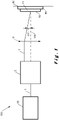
- the figure 1 shows the diagram of a possible embodiment of the structuring device 100 of the invention.
- the structuring device 100 comprises a light source 33 which is preferably a laser source and even more preferably a pulsed laser source which makes it possible to produce an incoming light beam 1.
- the structuring device 100 comprises an optical system 2 which makes it possible to obtain from the incoming light beam 1, an outgoing light beam 7 which is spatially offset from said incoming light beam 1.
- the outgoing light beam is focused on a substrate 11 by passing through a focusing means 9, a converging lens for example.
- a converging lens is for example of the symmetrical biconvex, asymmetrical biconvex, plano-convex or still converging meniscus.
- a converging lens is preferably spherical.
- the device 100 also comprises moving means 60 to move the substrate 11.
- the substrate 11 is positioned on a moving device 60 allowing the positioning of the substrate 11 relatively with respect to the outgoing light beam 7.
- the optical system 2 makes it possible to induce to the outgoing light beam 7 a rotational movement before passing through the focusing means 9.
- the outgoing light beam 7 before passing through the focusing means 9 is always parallel to itself whatever its position during its rotational motion.
- the optical system allows the lateral offset of the outgoing light beam 7 such that it is always parallel to itself.
- the projection of the outgoing light beam 7 on this plane during its rotational movement preferably describes a circle.
- the outgoing light beam 7 describes a precessional movement after having passed through the focusing means 9.
- the outgoing light beam 7 is focused on a point, a spot or a small surface on the substrate 11 to be machined or structured.
- the rotational movement imposed by the optical system 2 on the outgoing light beam 7 occurs around an axis 106 preferably called the precession axis.
- the axis around which the precession movement of the outgoing light beam 7 occurs is preferably aligned with the optical axis 106 of the focusing means 9.
- the outgoing light beam 7 is focused into a point, a spot or a small surface centered on the optical axis 106 of the focusing means 9.
- the focusing of the outgoing light beam 7 by the focusing means 9 takes place at a point, a task or a small focusing surface located at a distance on the axis optics 106 of the focusing means 9 consisting of a converging lens corresponding to the image focus of the lens convergent.
- the converging lens is positioned so that its image focus is at the level of the upper surface 16 of the substrate 11.
- the image focus of the converging lens (of the focusing means) can be moved deeper under the upper surface 16 of the substrate 11.
- the image focus of the focusing means 9 is moved in the depth of the substrate 11.
- the correct positioning of the image focus of the focusing means 9 makes it possible to obtain a structuring or an engraving having very straight and very clear edges, it that is to say without remelted zones for example.
- a convergent lens included in a focusing means 9 has a focal distance of between 10 mm and 160 mm, more preferably between 20 mm and 100 mm.
- the converging lens can be exchanged so that it is a focal length of 80 mm, 50 mm or 30 mm.
- a telecentric lens included in the focusing means 9 has a focal length of between 10 mm and 160 mm, more preferably between 20 mm and 100 mm.
- the telecentric lens is used when a deflection means is positioned between the optical system 2 and the focusing means 9.
- the amplitude of the lateral offset of the outgoing light beam 7 before passing through the focusing means 9 makes it possible to modify the angle of attack 107 of the outgoing light beam 7 with a normal 106 of the upper surface 16 of the substrate 11. Under these conditions, an increase in the amplitude of the lateral offset generates a greater angle of attack 107 value.
- the angle of attack 107 preferably has an angle of attack 107 of between 3° and 10°. Depending on the desired angle of attack and depending on the precision of the structuring or the desired machining, the focal length of the converging lens can be adapted.
- a converging lens with a focal length of 80 mm allows for example a maximum angle of attack 107 of approximately 5° and makes it possible to produce, for a position of the substrate 11, a structuring or a hole having a maximum dimension of 1000 ⁇ m and a dimension minimum of 90 ⁇ m.
- a converging lens with a focal length of 50 mm allows for example a maximum angle of attack 107 of approximately 7° and makes it possible to produce, for a position of the substrate 11, a structuring or a hole having a maximum dimension of 500 ⁇ m and a dimension minimum of 60 ⁇ m.
- a converging lens with a focal length of 30 mm allows for example a maximum angle of attack 107 of approximately 10° and makes it possible to produce, for a position of the substrate 11, a structuring or a hole having a maximum dimension of 200 ⁇ m and a dimension minimum of 40 ⁇ m.
- the choice of the focusing means and in the case of a converging lens, of its focal length makes it possible to modify the angle of attack 107 of the outgoing light beam 7 with a normal 106 issuing from the upper surface 16 of the substrate 11.
- the displacement means 60 are for example computer-controlled numerically controlled displacement means.
- the displacement means 60 allow for example to perform translations along 5 axes. In the configuration of an optical system 2 with mirror 19 movable in rotation, it is possible to define a continuous rotation of the mirror with an angular position of the mirror independent of the position of the substrate to be machined or structured. It is also possible to impose an angular position of the mirror 19 according to the position of the substrate to be machined or structured in order to be able to machine or structure the substrate 11 with an angle of incidence 107 for a certain position of the substrate 11.
- substrate holder 59 is positioned on the displacement means 60. The substrate holder 59 allows a good maintenance of the substrate relative to the displacement means 60. The substrate holder 59 allows a good transmission of the translation movements induced by the displacement means 60 to the substrate 11.
- the light source 33 is preferably a monochromatic light source of the laser type which can have wavelengths of 258 nm, 266 nm, 343 nm, 355 nm, 515 nm, 532 nm, 1030 nm and 1064 nm.
- the device 100 according to the invention allows the use of the wavelengths cited above without however being limited to other wavelengths in the range 250 nm to 1100 nm.
- the picture 2 shows an exemplary embodiment of the device 100 and in particular of the optical system 2 and of the displacement device 60.
- the incoming light beam 1 is a light beam generated by the light source 33 and preferably traveling outside the optical system 2 before entering it, while the incident light beam 4 travels only inside the optical system 2
- the incident light beam 4 can be obtained by the deflection of the incoming light beam 1 or without deflection of the incoming light beam 1.
- the incoming light beam 1 and the incident light beam 4 are on the same linear path.
- the optical system 2 comprises a mirror 19 which makes it possible to obtain a first reflected light beam 23 by the reflection of the incident light beam 4.
- the optical system 2 also comprises a retro-reflection system 21 which makes it possible to redirect the first reflected light beam 23 on the mirror 19.
- the second incident light beam 8 in the direction of the mirror 19 is obtained by the passage of the first reflected light beam 23 in the retro-reflection system 21.
- the second incident light beam 8 is then reflected by the mirror 19 and forms an outgoing light beam 7.
- the optical system 2 is configured such that the outgoing light beam 7 is spatially offset with respect to the incoming light beam 1 while remaining parallel to the direction of the incoming light beam 1 upstream of the focusing means 9. In the example shown by the picture 2 , the incoming light beam 1 and the outgoing light beam 7 are offset transversely.
- the mirror 19 can perform a complete rotation around an axis of rotation 5 and drive means 6 make it possible to put the mirror 19 in rotation around its axis of rotation 5.
- the optical system 2 of the device 100 is configured so the first incident light beam 4 and the normal 26 to the mirror 19 are separated by an angle 15 comprised between 0° and 15° for all the possible positions and orientations of the movable mirror 19. This angle 15 is not shown to scale on the picture 2 for clarity of the figure.
- the optical system 2 is configured so that a modification of position between the mirror 19 and the retro-reflection system 21 makes it possible to induce a variation of the shift between the incoming 1 and outgoing light beams 7.
- the optical system is for example mounted on a displacement plate.
- the outgoing light beam 7 will follow a different trajectory.
- each of the trajectories of the outgoing light beam 7 obtained for each of the angular positions of the mobile mirror 19 are parallel.
- the optical system 2 also comprises one or more focusing means 9 for focusing the outgoing light beam 7 on the substrate 11.
- the rotational movement of the outgoing light beam 7 generated by the rotation of the mirror 19 upstream of the focusing means 9, allows to produce the precession movement of the outgoing light beam 7 downstream of the focusing means 9.
- the precession movement of the outgoing light beam 7 is preferably produced at a point, a spot or a small surface on a substrate 11 intended to be structured or machined.
- the device comprises moving means 60 making it possible to move the substrate 11 relative to the outgoing light beam 7.
- the moving means 60 make it possible, for example, to move the substrate along the directions 101, 102 and 103.
- the directions 101, 102 and 103 preferably define a Cartesian coordinate system in three dimensions.
- means for imposing a translational movement of the movable mirror 19 and/or means allowing the inclination of the movable mirror 19 to be modified may be present (mirror 19 tiltable in two or more non-parallel directions and drive means capable of modifying the inclination of the mirror 19, these drive means being for example a piezoelectric system).
- the advantage of combining a translational movement and a rotational movement of the mirror 19 is to generate, by the relative rotational movement between the mirror 19 and the retro-reflection system 21, a precession of the outgoing light beam 7 downstream of the means of focusing 9, and, by the relative translation movement between the mirror 19 and the retro-reflection system 21, to modify the angle of attack 107 with the substrate 11.
- drive means are electric motors, brushless motors.
- the retro-reflection system 21 included in the optical system 2 comprises for example a Dove prism and an isosceles prism at right angles.
- Another embodiment of a retro-reflection system comprises for example a Dove prism, a right-angle isosceles prism, a half-wave plate, a roof prism and a polarizing semi-reflecting mirror.
- the figures 3a, 3b and 3c show the outgoing light beam 7 coming from the optical system 2 in three different positions during its precession movement downstream of the focusing means 9.
- the figures 3a, 3b and 3c show optical system 2 making it possible to generate an outgoing light beam 7 which is, upstream of the focusing means 9 shifted in space around the optical center 106 of the focusing means 9.
- the focusing means 9 being for example a converging lens.
- the picture 3a shows an outgoing light beam 7 shifted to the left of the optical center of the converging lens
- the figure 3b shows an outgoing light beam 7 shifted forwards or backwards from the optical center 106 of the converging lens
- the figure 3c shows an outgoing light beam 7 shifted to the right of the optical center 106.
- the forward or backward shift with respect to the optical center 106 illustrated by the figure 3b corresponds to the same distance as the offset to the left or to the right of the optical center 106 of the figures 3a and 3c .
- the projection described by the outgoing light beam 7 on the upstream surface of the converging lens 9 is a circle.
- the center of the circle described by the outgoing light beam 7 on the upstream surface of the convergent lens 9 coincides with the optical center of the convergent lens 9.
- the figures 3a, 3b and 3c show that the position of the outgoing light beam 7 on the converging lens makes it possible to modify the angle of attack 107 of the outgoing light beam 7 with a normal 106 to the upper surface 16 of the substrate 11.
- the angle of attack 107 of the beam outgoing light 7 is controlled thanks to the choice of the converging lens and the lateral offset of the outgoing light beam with respect to the optical center of the converging lens.
- the rotational movement of the outgoing light beam 7 upstream of the lens makes it possible to create a precessional movement downstream of the converging lens 9 which has an angle of attack which can be chosen.
- the substrate 11 is structured or machined with a controlled conicity.
- Controlling the angle of attack 107 makes it possible, for example, to compensate for the energy distribution of the laser beam in order to obtain structuring or machining with zero taper.
- the control of the angle of attack 107 makes it possible, for example, to compensate for the energy distribution of the laser beam in order to obtain structuring or machining with a negative taper.
- the figures 3a, 3b and 3c show positions of the outgoing light beam 7 focused allowing the formation of a structuring, a hole or a machining with negative conicity.
- the negative conicity is for example characterized by a negative conicity angle 108 described by a normal 106 to the upper surface 16 of the substrate 11 and an edge of the structuring or of the part machined by the outgoing light beam 7 focused.
- the position of the converging lens 9 is modified with respect to the upper surface 16 of the substrate in order to modify the position of the image focus of the lens and thus to modify the point, the spot or the small focal surface of the outgoing light beam 7.
- the depth of structuring is for example defined in a non-exhaustive manner by the speed of the precession, by the interval between each light pulse, by the quantity of energy of each light pulse, by the wavelength of the light beam, by the absorption coefficient of the substrate, by the physical properties of the substrate...
- the figure 4 shows a substrate structured according to an embodiment according to a second aspect of the invention.
- the figure 4 shows two parallel structures or patterns 17 in the form of grooves 17 formed according to the method of the invention. These grooves 17 are formed according to the method and in particular by carrying out the following steps: a) supplying the device 100; b) providing the substrate 11 so that it can be translated by the movement device 60 with respect to the focused outgoing light beam 7; c) generating with the light source 33 the incoming light beam 1 able to etch the substrate 11 from its upper surface 16; d) generating from the incoming light beam 1 during its passage through the optical system 2 and then through the focusing means 9, a focused outgoing light beam 7 describing a precession movement with respect to the upper surface 16 of the substrate 11; e) moving the substrate 11 relatively with respect to the focused outgoing light beam 7 describing a precessional movement by means of the displacement device 60 in order to etch a pattern 17 and more particularly grooves 17 from the upper surface 16 of said substrate 11, the grooves 17
- the formed patterns or grooves 17 each comprise a cavity 3 as well as side walls 8, the cavity 3 described in a plane essentially perpendicular to the upper surface 16, comprises at the level of its opening 4 on the upper surface 16 of the substrate 11, a first 51 and a second 52 ends defined by an intersection between the upper surface 16 and the side walls 8. It is possible to define an opening width 5 by the distance between the first 51 and the second 52 ends of the opening 4.
- a maximum width 6 of the cavity 3 is parallel to the upper surface 16 of the substrate 11 so that the maximum width 6 of the cavity 3 defines a first 61 and a second 62 end of the maximum width 6 with the side walls 8 of the cavity 3.
- a maximum depth 7 of the cavity 3 can also be described as being the depth of the groove 17 or of the structuring 17 with respect to the upper surface 16 of the subs 11.
- the opening width 5 of the cavity 3 is strictly smaller than the maximum width 6 of the cavity 3.
- the cavity 3 is shown on the figure 4 such as a groove 17 or a surface structure.
- the grooves or structuring having an opening width 5 of the cavity 3 smaller than the maximum width 6 or width under the surface are called grooves or structuring with negative conicity.
- the angle of negative conicity 108 described between a wall 8 of the groove 17 and a normal 106 to the upper surface 16 of the substrate 11 makes it possible to define the surface structuring. It is also possible to obtain a zero groove taper when the angle 108 is equal or very close to zero. A positive taper can also be obtained by the device and the method of the invention.
- the width 5 of the opening 4 of the structuring is preferably between 1 mm and 10 ⁇ m, more preferably between 500 ⁇ m and 30 ⁇ m and more preferably between 150 ⁇ m and 50 ⁇ m.
- the maximum width 6 of the structuring is preferably between 1.1 mm and 15 ⁇ m, more preferably between 550 ⁇ m and 45 ⁇ m and more preferably between 200 ⁇ m and 60 ⁇ m.
- the grooves have a depth 7 of the order of 10 to 200 ⁇ m.
- depth interval 7 is optimal for adhesion of the structured substrate 11 with a second material.
- a depth 7 of between 50 ⁇ m and 150 ⁇ m is particularly preferred.
- the figure 6 shows an example of grooves formed for a particular embodiment of the invention.
- the figure 6 shows in a plane essentially perpendicular to the upper surface 16 of the substrate 11, grooves formed and comprising a cavity 3.
- These grooves formed have a width which can vary but have a taper angle 108 with respect to a normal 106 to the upper surface 16 of the non-zero substrate 11.
- these grooves have a constant width in the thickness of the substrate and have a taper angle 108 with respect to a normal 106 to the upper surface 16 of the substrate 11 which is not zero.
- These grooves at an angle relative to a normal 106 present, in the direction of the normal 106, a part of the cavity 3 located under the upper surface 16 of the substrate and a part of the cavity located under the opening 4.
- Several grooves formed at an angle to the upper surface 16 with a width 5 in the thickness can be formed as illustrated in Figure 6 , that is to say by presenting a symmetry to each other in a section plane. For example, for a plurality of grooves, every other groove has the same orientation in a section plane.
- the formation of these oblique grooves requires, for example, an optical system 2 requiring a mobile mirror 19 and a redirection system which can be a simple mirror.
- grooves make it possible, for example, to obtain assembly properties with a second material comparable to those obtained with the grooves shown in Figure 4 .
- the grooves presented in Figure 6 can be seen as a decomposition of the mechanical anchoring property of the grooves presented in Figure 4 .
- the mechanical anchoring of a second material being created by the second material present under the surface of the substrate and not only under the opening 4.
- the oblique grooves as presented in Figure 6 allow, provided that they are sufficiently close together, to obtain a mechanical anchoring effect of a second material close to that created by the grooves in Figure 4 .
- the angle of the walls 8 of the oblique grooves with a normal 106 is preferably non-zero and more preferably between 0° and 30° and even more preferably between 1° and 20°.
- the oblique grooves have an opening width 5 which can vary along these grooves and present a conical profile.
- the formation of two or more cavities 3 on the upper surface 16 of a substrate 11 allows the creation of structures in order to obtain good mechanical anchoring of a second material and to obtain a cohesive rupture in the second material during a mechanical test.
- the second material is then inserted into the negative taper structuring via the upper surface of the substrate.
- the second material is a polymer which is polymerized inside the negative taper structure.
- the second material has a higher refractive index than the refractive index of the substrate.
- the second material comprises a polymer material and or more preferably poly(methyl methacrylate).
- a substrate comprising a metal, a glass, a ceramic or a polymeric material can for example be used in combination with the second material.
- the negative taper structuring comprising a second material allows the transport of an electromagnetic wave in a controlled manner, that is to say longitudinally to the structuring.
- the structuring is for example in a straight line or describing a curve or both.
- the optical coupling of the waveguide with another optical device can take place on one of the side faces of the substrate.
- the negative conical structuring, filled with a second material, allows the propagation of waves by multiple reflections (on the interfaces between the substrate 11 and the second material and on the surfaces between the second material and the air) in the manner of an optical fiber.
- An electrical circuit comprising a substrate 11 according to the third aspect of the invention is formed by inserting a conductive material into the negative taper structuring.
- the conductive material has for example a greater absorption coefficient than the absorption coefficient of the substrate 11 in the wavelength range 200 nm-2000 nm.
- the conductive material is for example tin which then has a lower melting point than that of the substrate 11.
- the substrate is a material having a high electrical resistance.
- the conductive material is, for example, melted and poured inside the structuring with negative conicity in order to at least partially fill the structuring with negative conicity.
- the substrate 11 is electrically insulating, that is to say it makes it possible to electrically insulate electrically conductive elements from each other.
- the conductive material in a viscous state is introduced by capillarity.
- the substrate 11 is for example a transparent material of the poly(ethylene terephthalate) (PET) or poly(ethylene naphthalate) (PEN) type for its insulating and mechanical flexibility.
- PET poly(ethylene terephthalate)
- PEN poly(ethylene naphthalate)
- a flexible material is a material that can be wrapped around a cylindrical support with a minimum diameter of 1 cm.
- a flexible material can be used in a continuous roll-to-roll deposition process.
- the substrate is bakelite.
- electrical connections can be made by placing a component to be electrically connected in contact with the conductive material through the opening 4 of the negative conicity and by locally heating the conductive material using a heating laser. desired location. The heating laser is for example transmitted through the transparent substrate.
- the conductive material preferably comprises a metal, tin or metallic particles.
Landscapes
- Physics & Mathematics (AREA)
- Optics & Photonics (AREA)
- Engineering & Computer Science (AREA)
- Mechanical Engineering (AREA)
- Plasma & Fusion (AREA)
- General Physics & Mathematics (AREA)
- Health & Medical Sciences (AREA)
- Electromagnetism (AREA)
- Toxicology (AREA)
- Laser Beam Processing (AREA)
- Exposure Of Semiconductors, Excluding Electron Or Ion Beam Exposure (AREA)
Applications Claiming Priority (2)
| Application Number | Priority Date | Filing Date | Title |
|---|---|---|---|
| BE2017/5455A BE1025341B1 (fr) | 2017-06-27 | 2017-06-27 | Méthode pour structurer un substrat |
| PCT/EP2018/067126 WO2019002301A1 (fr) | 2017-06-27 | 2018-06-26 | Methode de structurisation d'un substrat, ensemble comprenant un substrat et un dispositif de structuration dudit substrat, et substrat avec une telle structuration |
Publications (2)
| Publication Number | Publication Date |
|---|---|
| EP3645207A1 EP3645207A1 (fr) | 2020-05-06 |
| EP3645207B1 true EP3645207B1 (fr) | 2022-03-30 |
Family
ID=59337386
Family Applications (1)
| Application Number | Title | Priority Date | Filing Date |
|---|---|---|---|
| EP18732798.6A Active EP3645207B1 (fr) | 2017-06-27 | 2018-06-26 | Methode de structurisation d'un substrat, ensemble comprenant un substrat et un dispositif de structuration dudit substrat |
Country Status (7)
| Country | Link |
|---|---|
| US (1) | US11267072B2 (ja) |
| EP (1) | EP3645207B1 (ja) |
| JP (1) | JP7245791B2 (ja) |
| KR (1) | KR102509189B1 (ja) |
| CN (1) | CN110891730B (ja) |
| BE (1) | BE1025341B1 (ja) |
| WO (1) | WO2019002301A1 (ja) |
Family Cites Families (21)
| Publication number | Priority date | Publication date | Assignee | Title |
|---|---|---|---|---|
| US2758502A (en) * | 1952-10-08 | 1956-08-14 | Perkin Elmer Corp | Means for oscillating a beam in a plane |
| US6501045B1 (en) * | 2000-04-06 | 2002-12-31 | Resonetics, Inc. | Method and apparatus for controlling the taper angle of the walls of laser machined features |
| JP4311158B2 (ja) * | 2003-10-14 | 2009-08-12 | 株式会社デンソー | 樹脂成形品およびその製造方法 |
| WO2008110613A1 (de) * | 2007-03-13 | 2008-09-18 | Laser- Und Medizin-Technologie Gmbh Berlin | Vorrichtung und verfahren zum führen eines lichtstrahls |
| US9263172B2 (en) * | 2011-02-17 | 2016-02-16 | Advanced Bionics Ag | Wire constructs |
| CN202224847U (zh) * | 2011-08-16 | 2012-05-23 | 中科中涵激光设备(福建)股份有限公司 | 一种基于pzt与平行平板扫描倒锥孔的激光加工装置 |
| CN103056519B (zh) * | 2012-12-26 | 2014-11-26 | 中科中涵激光设备(福建)股份有限公司 | 一种锥度可控的激光微孔加工光束扫描装置及其控制方法 |
| CN103056525A (zh) * | 2012-12-28 | 2013-04-24 | 江苏大学 | 一种新型激光透射焊接连接方法 |
| CN103071923B (zh) * | 2012-12-28 | 2016-05-25 | 江苏大学 | 一种激光透射复合连接方法 |
| CN103071922B (zh) * | 2012-12-28 | 2016-08-03 | 江苏大学 | 一种高强度激光透射连接方法 |
| CN103057117A (zh) * | 2012-12-28 | 2013-04-24 | 江苏大学 | 一种提高激光透射焊接连接强度的方法 |
| PL2972479T3 (pl) * | 2013-03-13 | 2021-04-19 | Ipg Photonics (Canada) Inc. | Sposoby i układy do charakteryzacji właściwości obróbki laserem poprzez pomiar dynamiki kapilary z zastosowaniem interferometrii |
| US20140263212A1 (en) * | 2013-03-15 | 2014-09-18 | Electro Scientific Industries, Inc. | Coordination of beam angle and workpiece movement for taper control |
| DE102013226150A1 (de) * | 2013-12-17 | 2015-06-18 | Robert Bosch Gmbh | Verfahren zum Herstellen eines Elektronikmoduls mit formschlüssig angeschlossenem Gehäuseteilelement |
| DE102014008815A1 (de) * | 2014-06-11 | 2016-01-21 | Albis Plastic Gmbh | Verfahren zum Herstellen eines Werkstoffverbundes aus Metall und Kunststoff zu einem Kunststoff-Metall-Hybridbauteil |
| DE102014108259A1 (de) * | 2014-06-12 | 2015-12-17 | Scanlab Ag | Vorrichtung zur Lasermaterialbearbeitung |
| JP6451420B2 (ja) * | 2015-03-11 | 2019-01-16 | オムロン株式会社 | 接合構造体の製造方法 |
| WO2017029210A1 (en) * | 2015-08-14 | 2017-02-23 | Laser Engineering Applications | Machining device |
| CN105583525B (zh) * | 2016-01-27 | 2018-06-12 | 北京航空航天大学 | 一种用于聚合物/金属混合结构中界面微结构加工新方法 |
| CN106393705A (zh) * | 2016-07-26 | 2017-02-15 | 上海航天设备制造总厂 | 一种塑料和金属异质结构的连接方法 |
| CN106273414A (zh) * | 2016-08-11 | 2017-01-04 | 武汉凌云光电科技有限责任公司 | 一种塑料与金属永久性直接连接的制备方法 |
-
2017
- 2017-06-27 BE BE2017/5455A patent/BE1025341B1/fr not_active IP Right Cessation
-
2018
- 2018-06-26 JP JP2019570388A patent/JP7245791B2/ja active Active
- 2018-06-26 US US16/624,116 patent/US11267072B2/en active Active
- 2018-06-26 WO PCT/EP2018/067126 patent/WO2019002301A1/fr unknown
- 2018-06-26 EP EP18732798.6A patent/EP3645207B1/fr active Active
- 2018-06-26 KR KR1020197037403A patent/KR102509189B1/ko active IP Right Grant
- 2018-06-26 CN CN201880041046.4A patent/CN110891730B/zh active Active
Also Published As
| Publication number | Publication date |
|---|---|
| JP7245791B2 (ja) | 2023-03-24 |
| BE1025341A1 (fr) | 2019-01-29 |
| KR20200030033A (ko) | 2020-03-19 |
| BE1025341B1 (fr) | 2019-02-04 |
| WO2019002301A1 (fr) | 2019-01-03 |
| US11267072B2 (en) | 2022-03-08 |
| CN110891730B (zh) | 2022-09-06 |
| US20200130099A1 (en) | 2020-04-30 |
| KR102509189B1 (ko) | 2023-03-13 |
| JP2020525289A (ja) | 2020-08-27 |
| EP3645207A1 (fr) | 2020-05-06 |
| CN110891730A (zh) | 2020-03-17 |
Similar Documents
| Publication | Publication Date | Title |
|---|---|---|
| BE1024182B1 (fr) | Méthode de structuration d'un substrat | |
| EP3352974B1 (fr) | Systeme et procede de fabrication additive par fusion laser d'un lit de poudre | |
| EP2576127B2 (fr) | Procédé de gravure d'au moins une rainure formant des amorces de rupture à l'aide d'un dispositif laser à fibre optique | |
| WO2015055779A1 (fr) | Methode et dispositif de micro-usinage par laser | |
| CA2922526A1 (fr) | Dispositif et procede de marquage laser d'une lentille ophtalmique avec un laser pulse de longueur d'onde et energie par impulsion selectionnees | |
| WO2019207239A1 (fr) | Appareil et procédé pour fabriquer un objet tridimensionnel | |
| FR2777359A1 (fr) | Connexion d'une fibre optique et d'un guide d'ondes optique par fusion | |
| FR2952316A1 (fr) | Procede de soudure laser | |
| EP3645207B1 (fr) | Methode de structurisation d'un substrat, ensemble comprenant un substrat et un dispositif de structuration dudit substrat | |
| WO2016181088A2 (fr) | Dispositif de traitement laser et station de travail comportant un tel dispositif | |
| EP1945402A2 (fr) | Microtome laser femtoseconde pour decoupe par faisceau laser d'une tranche de matiere, notamment dans une cornee | |
| EP3515650B1 (fr) | Dispositif et procede de guidage d'un faisceau laser en deplacement rotatif et lateral pour faire varier l'excentrement du faisceau laser | |
| FR2900852A1 (fr) | Procede et appareil de trempe par choc laser | |
| BE1027700B1 (fr) | Dispositif pour un système optique d’usinage laser | |
| WO2016024069A1 (fr) | Dispositif d'usinage par faisceau laser d'un trou a conicite controlée avec un module afocal déplaçable | |
| FR2911080A1 (fr) | Procede et appareil de trempe par choc laser | |
| FR2872351A1 (fr) | Laser ultra-bref haute cadence avec conformation dynamique de faisceau | |
| WO2020012137A1 (fr) | Procede de nanostructuration de la surface d'un materiau par laser; ensemble permettant de mettre en oeuvre ce procede | |
| FR2702891A1 (fr) | Laser compact. |
Legal Events
| Date | Code | Title | Description |
|---|---|---|---|
| STAA | Information on the status of an ep patent application or granted ep patent |
Free format text: STATUS: UNKNOWN |
|
| STAA | Information on the status of an ep patent application or granted ep patent |
Free format text: STATUS: THE INTERNATIONAL PUBLICATION HAS BEEN MADE |
|
| PUAI | Public reference made under article 153(3) epc to a published international application that has entered the european phase |
Free format text: ORIGINAL CODE: 0009012 |
|
| STAA | Information on the status of an ep patent application or granted ep patent |
Free format text: STATUS: REQUEST FOR EXAMINATION WAS MADE |
|
| 17P | Request for examination filed |
Effective date: 20191216 |
|
| AK | Designated contracting states |
Kind code of ref document: A1 Designated state(s): AL AT BE BG CH CY CZ DE DK EE ES FI FR GB GR HR HU IE IS IT LI LT LU LV MC MK MT NL NO PL PT RO RS SE SI SK SM TR |
|
| AX | Request for extension of the european patent |
Extension state: BA ME |
|
| DAV | Request for validation of the european patent (deleted) | ||
| DAX | Request for extension of the european patent (deleted) | ||
| STAA | Information on the status of an ep patent application or granted ep patent |
Free format text: STATUS: EXAMINATION IS IN PROGRESS |
|
| STAA | Information on the status of an ep patent application or granted ep patent |
Free format text: STATUS: EXAMINATION IS IN PROGRESS |
|
| 17Q | First examination report despatched |
Effective date: 20201223 |
|
| GRAP | Despatch of communication of intention to grant a patent |
Free format text: ORIGINAL CODE: EPIDOSNIGR1 |
|
| STAA | Information on the status of an ep patent application or granted ep patent |
Free format text: STATUS: GRANT OF PATENT IS INTENDED |
|
| INTG | Intention to grant announced |
Effective date: 20211025 |
|
| GRAS | Grant fee paid |
Free format text: ORIGINAL CODE: EPIDOSNIGR3 |
|
| GRAA | (expected) grant |
Free format text: ORIGINAL CODE: 0009210 |
|
| STAA | Information on the status of an ep patent application or granted ep patent |
Free format text: STATUS: THE PATENT HAS BEEN GRANTED |
|
| AK | Designated contracting states |
Kind code of ref document: B1 Designated state(s): AL AT BE BG CH CY CZ DE DK EE ES FI FR GB GR HR HU IE IS IT LI LT LU LV MC MK MT NL NO PL PT RO RS SE SI SK SM TR |
|
| RAP3 | Party data changed (applicant data changed or rights of an application transferred) |
Owner name: LASER ENGINEERING APPLICATIONS |
|
| REG | Reference to a national code |
Ref country code: GB Ref legal event code: FG4D Free format text: NOT ENGLISH |
|
| REG | Reference to a national code |
Ref country code: CH Ref legal event code: EP |
|
| REG | Reference to a national code |
Ref country code: AT Ref legal event code: REF Ref document number: 1478722 Country of ref document: AT Kind code of ref document: T Effective date: 20220415 |
|
| REG | Reference to a national code |
Ref country code: DE Ref legal event code: R096 Ref document number: 602018032989 Country of ref document: DE |
|
| REG | Reference to a national code |
Ref country code: IE Ref legal event code: FG4D Free format text: LANGUAGE OF EP DOCUMENT: FRENCH |
|
| REG | Reference to a national code |
Ref country code: LT Ref legal event code: MG9D |
|
| REG | Reference to a national code |
Ref country code: NL Ref legal event code: FP |
|
| PG25 | Lapsed in a contracting state [announced via postgrant information from national office to epo] |
Ref country code: SE Free format text: LAPSE BECAUSE OF FAILURE TO SUBMIT A TRANSLATION OF THE DESCRIPTION OR TO PAY THE FEE WITHIN THE PRESCRIBED TIME-LIMIT Effective date: 20220330 Ref country code: RS Free format text: LAPSE BECAUSE OF FAILURE TO SUBMIT A TRANSLATION OF THE DESCRIPTION OR TO PAY THE FEE WITHIN THE PRESCRIBED TIME-LIMIT Effective date: 20220330 Ref country code: NO Free format text: LAPSE BECAUSE OF FAILURE TO SUBMIT A TRANSLATION OF THE DESCRIPTION OR TO PAY THE FEE WITHIN THE PRESCRIBED TIME-LIMIT Effective date: 20220630 Ref country code: LT Free format text: LAPSE BECAUSE OF FAILURE TO SUBMIT A TRANSLATION OF THE DESCRIPTION OR TO PAY THE FEE WITHIN THE PRESCRIBED TIME-LIMIT Effective date: 20220330 Ref country code: HR Free format text: LAPSE BECAUSE OF FAILURE TO SUBMIT A TRANSLATION OF THE DESCRIPTION OR TO PAY THE FEE WITHIN THE PRESCRIBED TIME-LIMIT Effective date: 20220330 Ref country code: BG Free format text: LAPSE BECAUSE OF FAILURE TO SUBMIT A TRANSLATION OF THE DESCRIPTION OR TO PAY THE FEE WITHIN THE PRESCRIBED TIME-LIMIT Effective date: 20220630 |
|
| PGFP | Annual fee paid to national office [announced via postgrant information from national office to epo] |
Ref country code: NL Payment date: 20220622 Year of fee payment: 5 Ref country code: GB Payment date: 20220627 Year of fee payment: 5 |
|
| REG | Reference to a national code |
Ref country code: AT Ref legal event code: MK05 Ref document number: 1478722 Country of ref document: AT Kind code of ref document: T Effective date: 20220330 |
|
| PG25 | Lapsed in a contracting state [announced via postgrant information from national office to epo] |
Ref country code: LV Free format text: LAPSE BECAUSE OF FAILURE TO SUBMIT A TRANSLATION OF THE DESCRIPTION OR TO PAY THE FEE WITHIN THE PRESCRIBED TIME-LIMIT Effective date: 20220330 Ref country code: GR Free format text: LAPSE BECAUSE OF FAILURE TO SUBMIT A TRANSLATION OF THE DESCRIPTION OR TO PAY THE FEE WITHIN THE PRESCRIBED TIME-LIMIT Effective date: 20220701 Ref country code: FI Free format text: LAPSE BECAUSE OF FAILURE TO SUBMIT A TRANSLATION OF THE DESCRIPTION OR TO PAY THE FEE WITHIN THE PRESCRIBED TIME-LIMIT Effective date: 20220330 |
|
| PGFP | Annual fee paid to national office [announced via postgrant information from national office to epo] |
Ref country code: FR Payment date: 20220622 Year of fee payment: 5 |
|
| PG25 | Lapsed in a contracting state [announced via postgrant information from national office to epo] |
Ref country code: SM Free format text: LAPSE BECAUSE OF FAILURE TO SUBMIT A TRANSLATION OF THE DESCRIPTION OR TO PAY THE FEE WITHIN THE PRESCRIBED TIME-LIMIT Effective date: 20220330 Ref country code: SK Free format text: LAPSE BECAUSE OF FAILURE TO SUBMIT A TRANSLATION OF THE DESCRIPTION OR TO PAY THE FEE WITHIN THE PRESCRIBED TIME-LIMIT Effective date: 20220330 Ref country code: RO Free format text: LAPSE BECAUSE OF FAILURE TO SUBMIT A TRANSLATION OF THE DESCRIPTION OR TO PAY THE FEE WITHIN THE PRESCRIBED TIME-LIMIT Effective date: 20220330 Ref country code: PT Free format text: LAPSE BECAUSE OF FAILURE TO SUBMIT A TRANSLATION OF THE DESCRIPTION OR TO PAY THE FEE WITHIN THE PRESCRIBED TIME-LIMIT Effective date: 20220801 Ref country code: ES Free format text: LAPSE BECAUSE OF FAILURE TO SUBMIT A TRANSLATION OF THE DESCRIPTION OR TO PAY THE FEE WITHIN THE PRESCRIBED TIME-LIMIT Effective date: 20220330 Ref country code: EE Free format text: LAPSE BECAUSE OF FAILURE TO SUBMIT A TRANSLATION OF THE DESCRIPTION OR TO PAY THE FEE WITHIN THE PRESCRIBED TIME-LIMIT Effective date: 20220330 Ref country code: CZ Free format text: LAPSE BECAUSE OF FAILURE TO SUBMIT A TRANSLATION OF THE DESCRIPTION OR TO PAY THE FEE WITHIN THE PRESCRIBED TIME-LIMIT Effective date: 20220330 Ref country code: AT Free format text: LAPSE BECAUSE OF FAILURE TO SUBMIT A TRANSLATION OF THE DESCRIPTION OR TO PAY THE FEE WITHIN THE PRESCRIBED TIME-LIMIT Effective date: 20220330 |
|
| PGFP | Annual fee paid to national office [announced via postgrant information from national office to epo] |
Ref country code: DE Payment date: 20220628 Year of fee payment: 5 |
|
| PG25 | Lapsed in a contracting state [announced via postgrant information from national office to epo] |
Ref country code: PL Free format text: LAPSE BECAUSE OF FAILURE TO SUBMIT A TRANSLATION OF THE DESCRIPTION OR TO PAY THE FEE WITHIN THE PRESCRIBED TIME-LIMIT Effective date: 20220330 Ref country code: IS Free format text: LAPSE BECAUSE OF FAILURE TO SUBMIT A TRANSLATION OF THE DESCRIPTION OR TO PAY THE FEE WITHIN THE PRESCRIBED TIME-LIMIT Effective date: 20220730 Ref country code: AL Free format text: LAPSE BECAUSE OF FAILURE TO SUBMIT A TRANSLATION OF THE DESCRIPTION OR TO PAY THE FEE WITHIN THE PRESCRIBED TIME-LIMIT Effective date: 20220330 |
|
| PGFP | Annual fee paid to national office [announced via postgrant information from national office to epo] |
Ref country code: CH Payment date: 20220628 Year of fee payment: 5 |
|
| REG | Reference to a national code |
Ref country code: DE Ref legal event code: R097 Ref document number: 602018032989 Country of ref document: DE |
|
| PG25 | Lapsed in a contracting state [announced via postgrant information from national office to epo] |
Ref country code: MC Free format text: LAPSE BECAUSE OF FAILURE TO SUBMIT A TRANSLATION OF THE DESCRIPTION OR TO PAY THE FEE WITHIN THE PRESCRIBED TIME-LIMIT Effective date: 20220330 Ref country code: DK Free format text: LAPSE BECAUSE OF FAILURE TO SUBMIT A TRANSLATION OF THE DESCRIPTION OR TO PAY THE FEE WITHIN THE PRESCRIBED TIME-LIMIT Effective date: 20220330 |
|
| PLBE | No opposition filed within time limit |
Free format text: ORIGINAL CODE: 0009261 |
|
| STAA | Information on the status of an ep patent application or granted ep patent |
Free format text: STATUS: NO OPPOSITION FILED WITHIN TIME LIMIT |
|
| 26N | No opposition filed |
Effective date: 20230103 |
|
| PG25 | Lapsed in a contracting state [announced via postgrant information from national office to epo] |
Ref country code: LU Free format text: LAPSE BECAUSE OF NON-PAYMENT OF DUE FEES Effective date: 20220626 Ref country code: IE Free format text: LAPSE BECAUSE OF NON-PAYMENT OF DUE FEES Effective date: 20220626 |
|
| PG25 | Lapsed in a contracting state [announced via postgrant information from national office to epo] |
Ref country code: SI Free format text: LAPSE BECAUSE OF FAILURE TO SUBMIT A TRANSLATION OF THE DESCRIPTION OR TO PAY THE FEE WITHIN THE PRESCRIBED TIME-LIMIT Effective date: 20220330 |
|
| P01 | Opt-out of the competence of the unified patent court (upc) registered |
Effective date: 20230529 |
|
| PG25 | Lapsed in a contracting state [announced via postgrant information from national office to epo] |
Ref country code: IT Free format text: LAPSE BECAUSE OF FAILURE TO SUBMIT A TRANSLATION OF THE DESCRIPTION OR TO PAY THE FEE WITHIN THE PRESCRIBED TIME-LIMIT Effective date: 20220330 |
|
| PGFP | Annual fee paid to national office [announced via postgrant information from national office to epo] |
Ref country code: BE Payment date: 20230530 Year of fee payment: 6 |
|
| REG | Reference to a national code |
Ref country code: DE Ref legal event code: R119 Ref document number: 602018032989 Country of ref document: DE |
|
| REG | Reference to a national code |
Ref country code: CH Ref legal event code: PL |
|
| REG | Reference to a national code |
Ref country code: NL Ref legal event code: MM Effective date: 20230701 |
|
| GBPC | Gb: european patent ceased through non-payment of renewal fee |
Effective date: 20230626 |
|
| PG25 | Lapsed in a contracting state [announced via postgrant information from national office to epo] |
Ref country code: NL Free format text: LAPSE BECAUSE OF NON-PAYMENT OF DUE FEES Effective date: 20230701 |
|
| PG25 | Lapsed in a contracting state [announced via postgrant information from national office to epo] |
Ref country code: MK Free format text: LAPSE BECAUSE OF FAILURE TO SUBMIT A TRANSLATION OF THE DESCRIPTION OR TO PAY THE FEE WITHIN THE PRESCRIBED TIME-LIMIT Effective date: 20220330 Ref country code: DE Free format text: LAPSE BECAUSE OF NON-PAYMENT OF DUE FEES Effective date: 20240103 Ref country code: CY Free format text: LAPSE BECAUSE OF FAILURE TO SUBMIT A TRANSLATION OF THE DESCRIPTION OR TO PAY THE FEE WITHIN THE PRESCRIBED TIME-LIMIT Effective date: 20220330 Ref country code: CH Free format text: LAPSE BECAUSE OF NON-PAYMENT OF DUE FEES Effective date: 20230630 Ref country code: GB Free format text: LAPSE BECAUSE OF NON-PAYMENT OF DUE FEES Effective date: 20230626 |