EP3643671A1 - Elevator seismic performance apparatus - Google Patents
Elevator seismic performance apparatus Download PDFInfo
- Publication number
- EP3643671A1 EP3643671A1 EP19175004.1A EP19175004A EP3643671A1 EP 3643671 A1 EP3643671 A1 EP 3643671A1 EP 19175004 A EP19175004 A EP 19175004A EP 3643671 A1 EP3643671 A1 EP 3643671A1
- Authority
- EP
- European Patent Office
- Prior art keywords
- car
- elevator
- seismic
- upright
- elevator system
- Prior art date
- Legal status (The legal status is an assumption and is not a legal conclusion. Google has not performed a legal analysis and makes no representation as to the accuracy of the status listed.)
- Pending
Links
- 230000000712 assembly Effects 0.000 claims abstract description 10
- 238000000429 assembly Methods 0.000 claims abstract description 10
- 230000003319 supportive effect Effects 0.000 claims abstract description 5
- 230000009467 reduction Effects 0.000 description 2
- 230000001133 acceleration Effects 0.000 description 1
- 230000002452 interceptive effect Effects 0.000 description 1
- 238000005259 measurement Methods 0.000 description 1
- 238000000034 method Methods 0.000 description 1
- 238000012986 modification Methods 0.000 description 1
- 230000004048 modification Effects 0.000 description 1
Images



Classifications
-
- B—PERFORMING OPERATIONS; TRANSPORTING
- B66—HOISTING; LIFTING; HAULING
- B66B—ELEVATORS; ESCALATORS OR MOVING WALKWAYS
- B66B5/00—Applications of checking, fault-correcting, or safety devices in elevators
- B66B5/02—Applications of checking, fault-correcting, or safety devices in elevators responsive to abnormal operating conditions
- B66B5/021—Applications of checking, fault-correcting, or safety devices in elevators responsive to abnormal operating conditions the abnormal operating conditions being independent of the system
- B66B5/022—Applications of checking, fault-correcting, or safety devices in elevators responsive to abnormal operating conditions the abnormal operating conditions being independent of the system where the abnormal operating condition is caused by a natural event, e.g. earthquake
-
- B—PERFORMING OPERATIONS; TRANSPORTING
- B66—HOISTING; LIFTING; HAULING
- B66B—ELEVATORS; ESCALATORS OR MOVING WALKWAYS
- B66B11/00—Main component parts of lifts in, or associated with, buildings or other structures
- B66B11/02—Cages, i.e. cars
- B66B11/0206—Car frames
-
- B—PERFORMING OPERATIONS; TRANSPORTING
- B66—HOISTING; LIFTING; HAULING
- B66B—ELEVATORS; ESCALATORS OR MOVING WALKWAYS
- B66B11/00—Main component parts of lifts in, or associated with, buildings or other structures
- B66B11/02—Cages, i.e. cars
- B66B11/0206—Car frames
- B66B11/0213—Car frames for multi-deck cars
-
- B—PERFORMING OPERATIONS; TRANSPORTING
- B66—HOISTING; LIFTING; HAULING
- B66B—ELEVATORS; ESCALATORS OR MOVING WALKWAYS
- B66B11/00—Main component parts of lifts in, or associated with, buildings or other structures
- B66B11/02—Cages, i.e. cars
- B66B11/0226—Constructional features, e.g. walls assembly, decorative panels, comfort equipment, thermal or sound insulation
-
- B—PERFORMING OPERATIONS; TRANSPORTING
- B66—HOISTING; LIFTING; HAULING
- B66B—ELEVATORS; ESCALATORS OR MOVING WALKWAYS
- B66B11/00—Main component parts of lifts in, or associated with, buildings or other structures
- B66B11/02—Cages, i.e. cars
- B66B11/026—Attenuation system for shocks, vibrations, imbalance, e.g. passengers on the same side
- B66B11/0266—Passive systems
-
- B—PERFORMING OPERATIONS; TRANSPORTING
- B66—HOISTING; LIFTING; HAULING
- B66B—ELEVATORS; ESCALATORS OR MOVING WALKWAYS
- B66B5/00—Applications of checking, fault-correcting, or safety devices in elevators
- B66B5/02—Applications of checking, fault-correcting, or safety devices in elevators responsive to abnormal operating conditions
- B66B5/16—Braking or catch devices operating between cars, cages, or skips and fixed guide elements or surfaces in hoistway or well
-
- B—PERFORMING OPERATIONS; TRANSPORTING
- B66—HOISTING; LIFTING; HAULING
- B66B—ELEVATORS; ESCALATORS OR MOVING WALKWAYS
- B66B5/00—Applications of checking, fault-correcting, or safety devices in elevators
- B66B5/02—Applications of checking, fault-correcting, or safety devices in elevators responsive to abnormal operating conditions
- B66B5/16—Braking or catch devices operating between cars, cages, or skips and fixed guide elements or surfaces in hoistway or well
- B66B5/26—Positively-acting devices, e.g. latches, knives
-
- B—PERFORMING OPERATIONS; TRANSPORTING
- B66—HOISTING; LIFTING; HAULING
- B66B—ELEVATORS; ESCALATORS OR MOVING WALKWAYS
- B66B7/00—Other common features of elevators
- B66B7/02—Guideways; Guides
- B66B7/023—Mounting means therefor
-
- B—PERFORMING OPERATIONS; TRANSPORTING
- B66—HOISTING; LIFTING; HAULING
- B66B—ELEVATORS; ESCALATORS OR MOVING WALKWAYS
- B66B7/00—Other common features of elevators
- B66B7/02—Guideways; Guides
- B66B7/028—Guideways; Guides with earthquake protection devices
-
- B—PERFORMING OPERATIONS; TRANSPORTING
- B66—HOISTING; LIFTING; HAULING
- B66B—ELEVATORS; ESCALATORS OR MOVING WALKWAYS
- B66B7/00—Other common features of elevators
- B66B7/06—Arrangements of ropes or cables
- B66B7/10—Arrangements of ropes or cables for equalising rope or cable tension
Definitions
- Exemplary embodiments pertain to the art of elevator systems, and more particularly to improving elevator system performance during seismic events.
- Elevator systems must typically comply with jurisdictional rules for performance of the elevator system under various operating conditions. Such rules are set forth in codes issued by various code setting bodies. Some such codes specify standards for performance and safety of the elevator system in the case of a seismic event. Current configurations for meeting seismic requirements can result in high rail and car frame loading during a seismic event, resulting in large guide rail sizes in order to meet the seismic performance requirements, thus greatly increasing cost of the elevator system. Such issues are exacerbated in high-rise elevator systems and those with double-deck elevator car structures.
- an elevator car of an elevator system includes a car body, and a car frame supportive of the car body.
- the car frame includes two or more opposing upright assemblies, a crosshead assembly located above the car body, and a plank assembly located below the car body.
- a plurality of seismic retainers are located at each of the upright assemblies. The plurality of seismic retainers are configured for a non-contact relationship with a guide rail of the elevator system during normal operation of the elevator system, and configured to react guide rail loads during a sway event via contact with the guide rail.
- the seismic retainer includes a retainer slot having a retainer slot width greater than a blade width of the guide rail disposed in the retainer slot.
- three or more seismic retainers are located at each upright assembly.
- two or more car bodies are located between the cross head assembly and the plank assembly.
- each upright assembly includes two or more vertically extending upright members, and a plurality of upright braces extending between the upright members.
- the plurality of seismic retainers are located at the plurality of upright braces.
- one or more elevator car guides are located at the elevator car and configured for contact with the guide rail during normal operating conditions of the elevator system.
- an elevator system in another embodiment, includes one or more guide rails, and an elevator car operably connected to and movable along the one or more guide rails.
- the elevator car includes a car body and a car frame supportive of the car body.
- the car frame includes two or more opposing upright assemblies, a crosshead assembly located above the car body, and a plank assembly located below the car body.
- a plurality of seismic retainers are located at each of the upright assemblies. The plurality of seismic retainers are configured for a non-contact relationship with a guide rail of the elevator system during normal operation of the elevator system, and are configured to react guide rail loads during a seismic or rope sway event via contact with the guide rail.
- the seismic retainer includes a retainer slot having a retainer slot width greater than a blade width of the guide rail located in the retainer slot.
- three or more seismic retainers are located at each upright assembly.
- two or more car bodies are located between the crosshead assembly and the plank assembly.
- each upright assembly includes two or more vertically extending upright members, and a plurality of upright braces extending between the upright members.
- the plurality of seismic retainers are located at the plurality of upright braces.
- one or more elevator car guides are located at the elevator car configured for contact with the guide rail during normal operating conditions of the elevator system.
- FIG. 1 Shown in FIG. 1 is a schematic view of an exemplary traction elevator system 10.
- the elevator system 10 includes an elevator car 14 operatively suspended or supported in a hoistway 12 with one or more load bearing members, such as a rope or a belt 16.
- the belt 16 interacts with sheaves 18 and 52 to be routed around various components of the elevator system 10.
- Sheave 18 is configured as a diverter, deflector or idler sheave and sheave 52 is configured as a traction sheave, driven by a machine 50. Movement of the traction sheave 52 by the machine 50 drives, moves and/or propels (through traction) the belt 16 that is routed around the traction sheave 52.
- Diverter, deflector or idler sheaves 18 are not driven by a machine 50, but help guide the belt 16 around the various components of the elevator system 10.
- the belt 16 could also be connected to a counterweight 22, which is used to help balance the elevator system 10 and reduce the difference in belt tension on both sides of the traction sheave 52 during operation.
- the sheaves 18 and 52 each have a diameter, which may be the same or different from each other.
- the elevator system 10 could use two or more belts 16 for suspending and/or driving the elevator car 14
- the elevator system 10 could have various configurations such that either both sides of the one or more belts 16 engage the sheaves 18, 52 or only one side of the one or more belts 16 engages the sheaves 18, 52.
- the embodiment of FIG 1 shows a 1:1 roping arrangement in which the one or more belts 16 terminate at the car 14 and counterweight 22, while other embodiments may utilize other roping arrangements.
- the elevator car 14 travels in the hoistway 12 along a path of one or more guide rails 24 arranged in the hoistway 12.
- the elevator car 14 includes a car body 26 affixed to a car frame 28.
- the elevator car 14 is a double deck configuration, with two car bodies 26 affixed to a common car frame 28.
- While the embodiments disclosed herein include two car bodies 26 affixed to the car frame 28, it is to be appreciated that the present disclosure may be utilized with other elevator car 14 configurations, such as those with one car body 26 or three or more car bodies 26 affixed to a common car frame 28.
- Car guides 30 mounted at the elevator car 14 interact with the guide rails 24, thereby guiding the elevator car 14 along the path of the guide rails 24.
- the elevator car 14 includes four car guides 30, with two car guides 30 located to be interactive with each of the guide rails 24.
- the car guide 30 includes a guide base 32 fixed to the elevator car 14. A plurality of guide wheels 34 are secured to the guide base 32. As the elevator car 14 travels along the hoistway 12, the guide wheels 34 remain in contact with the guide rail 24.
- the car frame 28 includes a side frame 36 or upright assembly at each lateral side of the car frame 28, with a crosshead assembly 38 and a plank assembly 40 extending between the side frames 36 and defining an upper extent and a lower extent, respectively, of the car frame 28.
- Intermediate cross members 42 support the car bodies 26 in the car frame 28.
- the side frame 36 includes upright members 44 and upright braces 46 connecting the upright members 44 to provide support to the upright members 44.
- a plurality of seismic retainers 48 are located along the side frames 36 to react loads during seismic events or other sway events. In some embodiments, such as in FIG.
- the seismic retainers 48 are located at the upright braces 46, while in other embodiments the seismic retainers 48 may be positioned at other locations, such as at the upright members 44. While 8 seismic retainers 48 are illustrated at the side frame 36 of FIG. 4 , it is to be appreciated that other quantities of seismic retainers 48 may be utilized. In some embodiments, three or more seismic retainers 48 ae utilized. Further, in other embodiments, the side frame 36 includes a single upright member 44 with the seismic retainers 48 secured to the upright member 44.
- the seismic retainer 48 includes a retainer plate 50 secured to the upright brace 46 via two retainer brackets 52.
- the retainer plate 50 includes a rail slot 54 sized and positioned for a non-contact relationship with the guide rail 24 during normal operating conditions of the elevator system 10.
- a rail blade 56 of the guide rail 24 is located in the rail slot 54 between a first slot side 58 and a second slot side 60 opposite the first slot side 58.
- the first slot side 58 and the second slot side 60 define a rail slot width 62, which is greater than a blade width 64 of the rail blade 56.
- the seismic retainer 48 reacts guide rail loads via contact with the guide rail 24 during the event, and by providing a plurality of seismic retainers 48 the guide rail loads are distributed throughout the plurality of seismic retainers 48.
- a plurality of retainer plates 50 are utilized in the illustrated embodiments, it is to be appreciated that in other embodiments one or more intermediate roller guides or sliding guides may be substituted for any of the seismic retainers 48, to further help distribute loading on the rails for either a seismic loading event, or with normal running conditions to help reduce deflections of car frame 28 structure.
- a quantity and/or spacing of the seismic retainers 48 may be varied. Further, properties of the seismic retainer 48, such as rail slot width 62 or retainer plate 50 thickness may be varied to meet elevator system 10 requirements. Further, wear pads 66 may be included in the rail slot 54 to mitigate wear and noise due to contact between the guide rail 24 and the retainer plate 50.
- seismic retainers 48 allows for reduction in guide rail 24 size, and/or reduces the quantity of rail brackets necessary to fix the guide rail 24 in the hoistway 12 for sway event load reaction. These material reductions, which are especially significant in high rise elevators, such as those having hoistways 12 of 100 meters or more, and results in a significant cost savings for the elevator system 10.
Landscapes
- Engineering & Computer Science (AREA)
- Mechanical Engineering (AREA)
- Civil Engineering (AREA)
- Structural Engineering (AREA)
- Remote Sensing (AREA)
- Environmental & Geological Engineering (AREA)
- General Life Sciences & Earth Sciences (AREA)
- Geology (AREA)
- Life Sciences & Earth Sciences (AREA)
- Business, Economics & Management (AREA)
- Emergency Management (AREA)
- Physics & Mathematics (AREA)
- Fluid Mechanics (AREA)
- Lift-Guide Devices, And Elevator Ropes And Cables (AREA)
- Maintenance And Inspection Apparatuses For Elevators (AREA)
- Cage And Drive Apparatuses For Elevators (AREA)
Abstract
Description
- Exemplary embodiments pertain to the art of elevator systems, and more particularly to improving elevator system performance during seismic events.
- Elevator systems must typically comply with jurisdictional rules for performance of the elevator system under various operating conditions. Such rules are set forth in codes issued by various code setting bodies. Some such codes specify standards for performance and safety of the elevator system in the case of a seismic event. Current configurations for meeting seismic requirements can result in high rail and car frame loading during a seismic event, resulting in large guide rail sizes in order to meet the seismic performance requirements, thus greatly increasing cost of the elevator system. Such issues are exacerbated in high-rise elevator systems and those with double-deck elevator car structures.
- In one embodiment, an elevator car of an elevator system includes a car body, and a car frame supportive of the car body. The car frame includes two or more opposing upright assemblies, a crosshead assembly located above the car body, and a plank assembly located below the car body. A plurality of seismic retainers are located at each of the upright assemblies. The plurality of seismic retainers are configured for a non-contact relationship with a guide rail of the elevator system during normal operation of the elevator system, and configured to react guide rail loads during a sway event via contact with the guide rail.
- Additionally or alternatively, in this or other embodiments the seismic retainer includes a retainer slot having a retainer slot width greater than a blade width of the guide rail disposed in the retainer slot.
- Additionally or alternatively, in this or other embodiments three or more seismic retainers are located at each upright assembly.
- Additionally or alternatively, in this or other embodiments two or more car bodies are located between the cross head assembly and the plank assembly.
- Additionally or alternatively, in this or other embodiments each upright assembly includes two or more vertically extending upright members, and a plurality of upright braces extending between the upright members.
- Additionally or alternatively, in this or other embodiments the plurality of seismic retainers are located at the plurality of upright braces.
- Additionally or alternatively, in this or other embodiments one or more elevator car guides are located at the elevator car and configured for contact with the guide rail during normal operating conditions of the elevator system.
- In another embodiment, an elevator system includes one or more guide rails, and an elevator car operably connected to and movable along the one or more guide rails. The elevator car includes a car body and a car frame supportive of the car body. The car frame includes two or more opposing upright assemblies, a crosshead assembly located above the car body, and a plank assembly located below the car body. A plurality of seismic retainers are located at each of the upright assemblies. The plurality of seismic retainers are configured for a non-contact relationship with a guide rail of the elevator system during normal operation of the elevator system, and are configured to react guide rail loads during a seismic or rope sway event via contact with the guide rail.
- Additionally or alternatively, in this or other embodiments the seismic retainer includes a retainer slot having a retainer slot width greater than a blade width of the guide rail located in the retainer slot.
- Additionally or alternatively, in this or other embodiments three or more seismic retainers are located at each upright assembly.
- Additionally or alternatively, in this or other embodiments two or more car bodies are located between the crosshead assembly and the plank assembly.
- Additionally or alternatively, in this or other embodiments each upright assembly includes two or more vertically extending upright members, and a plurality of upright braces extending between the upright members.
- Additionally or alternatively, in this or other embodiments the plurality of seismic retainers are located at the plurality of upright braces.
- Additionally or alternatively, in this or other embodiments one or more elevator car guides are located at the elevator car configured for contact with the guide rail during normal operating conditions of the elevator system.
- The following descriptions should not be considered limiting in any way. With reference to the accompanying drawings, like elements are numbered alike:
-
FIG. 1 is a schematic view of an embodiment of an elevator system; -
FIG. 2 is another schematic view of an embodiment of an elevator system; -
FIG. 3 is a perspective view of an embodiment of an elevator car guide of an elevator system; -
FIG. 4 is a perspective view of an embodiment of a car frame of an elevator system; -
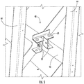
FIG. 5 is a perspective view of an embodiment of a seismic retainer for an elevator car; and -
FIG. 6 is a plan view of an embodiment of a seismic retainer for an elevator car. - A detailed description of one or more embodiments of the disclosed apparatus and method are presented herein by way of exemplification and not limitation with reference to the Figures.
- Shown in
FIG. 1 is a schematic view of an exemplarytraction elevator system 10. Theelevator system 10 includes anelevator car 14 operatively suspended or supported in ahoistway 12 with one or more load bearing members, such as a rope or abelt 16. Thebelt 16 interacts withsheaves elevator system 10. Sheave 18 is configured as a diverter, deflector or idler sheave andsheave 52 is configured as a traction sheave, driven by amachine 50. Movement of thetraction sheave 52 by themachine 50 drives, moves and/or propels (through traction) thebelt 16 that is routed around thetraction sheave 52. Diverter, deflector oridler sheaves 18 are not driven by amachine 50, but help guide thebelt 16 around the various components of theelevator system 10. Thebelt 16 could also be connected to acounterweight 22, which is used to help balance theelevator system 10 and reduce the difference in belt tension on both sides of thetraction sheave 52 during operation. Thesheaves - In some embodiments, the
elevator system 10 could use two ormore belts 16 for suspending and/or driving theelevator car 14 In addition, theelevator system 10 could have various configurations such that either both sides of the one ormore belts 16 engage thesheaves more belts 16 engages thesheaves FIG 1 shows a 1:1 roping arrangement in which the one ormore belts 16 terminate at thecar 14 andcounterweight 22, while other embodiments may utilize other roping arrangements. - Referring to
FIG. 2 , theelevator car 14 travels in thehoistway 12 along a path of one ormore guide rails 24 arranged in thehoistway 12. In the embodiment ofFIG. 2 , twoguide rails 24 located at opposing sides of theelevator car 14 are utilized, but it is to be appreciated that in other embodiments other numbers ofguide rails 24 may be utilized, such as one or fourguide rails 24. Theelevator car 14 includes acar body 26 affixed to acar frame 28. In some embodiments, such as illustrated inFIG. 2 , theelevator car 14 is a double deck configuration, with twocar bodies 26 affixed to acommon car frame 28. While the embodiments disclosed herein include twocar bodies 26 affixed to thecar frame 28, it is to be appreciated that the present disclosure may be utilized withother elevator car 14 configurations, such as those with onecar body 26 or three ormore car bodies 26 affixed to acommon car frame 28. -
Car guides 30 mounted at theelevator car 14 interact with theguide rails 24, thereby guiding theelevator car 14 along the path of theguide rails 24. In some embodiments, such as shown inFIG. 2 , theelevator car 14 includes fourcar guides 30, with twocar guides 30 located to be interactive with each of theguide rails 24. As shown inFIG. 3 , thecar guide 30 includes aguide base 32 fixed to theelevator car 14. A plurality ofguide wheels 34 are secured to theguide base 32. As theelevator car 14 travels along thehoistway 12, theguide wheels 34 remain in contact with theguide rail 24. - Referring now to
FIG. 4 , thecar frame 28 is illustrated in more detail. Thecar frame 28 includes aside frame 36 or upright assembly at each lateral side of thecar frame 28, with acrosshead assembly 38 and aplank assembly 40 extending between theside frames 36 and defining an upper extent and a lower extent, respectively, of thecar frame 28.Intermediate cross members 42 support thecar bodies 26 in thecar frame 28. Theside frame 36 includesupright members 44 andupright braces 46 connecting theupright members 44 to provide support to theupright members 44. A plurality ofseismic retainers 48 are located along theside frames 36 to react loads during seismic events or other sway events. In some embodiments, such as inFIG. 4 , theseismic retainers 48 are located at the upright braces 46, while in other embodiments theseismic retainers 48 may be positioned at other locations, such as at theupright members 44. While 8seismic retainers 48 are illustrated at theside frame 36 ofFIG. 4 , it is to be appreciated that other quantities ofseismic retainers 48 may be utilized. In some embodiments, three or moreseismic retainers 48 ae utilized. Further, in other embodiments, theside frame 36 includes asingle upright member 44 with theseismic retainers 48 secured to theupright member 44. - Referring now to
FIG. 5 , theseismic retainer 48 includes aretainer plate 50 secured to theupright brace 46 via tworetainer brackets 52. As shown best inFIG. 6 , theretainer plate 50 includes arail slot 54 sized and positioned for a non-contact relationship with theguide rail 24 during normal operating conditions of theelevator system 10. Arail blade 56 of theguide rail 24 is located in therail slot 54 between afirst slot side 58 and asecond slot side 60 opposite thefirst slot side 58. Thefirst slot side 58 and thesecond slot side 60 define arail slot width 62, which is greater than a blade width 64 of therail blade 56. During a seismic event or other building sway event including lateral accelerations of theelevator car 14, theseismic retainer 48 reacts guide rail loads via contact with theguide rail 24 during the event, and by providing a plurality ofseismic retainers 48 the guide rail loads are distributed throughout the plurality ofseismic retainers 48. Although a plurality ofretainer plates 50 are utilized in the illustrated embodiments, it is to be appreciated that in other embodiments one or more intermediate roller guides or sliding guides may be substituted for any of theseismic retainers 48, to further help distribute loading on the rails for either a seismic loading event, or with normal running conditions to help reduce deflections ofcar frame 28 structure. - Depending on the system requirements, a quantity and/or spacing of the
seismic retainers 48 may be varied. Further, properties of theseismic retainer 48, such asrail slot width 62 orretainer plate 50 thickness may be varied to meetelevator system 10 requirements. Further, wearpads 66 may be included in therail slot 54 to mitigate wear and noise due to contact between theguide rail 24 and theretainer plate 50. - Use of the
seismic retainers 48 allows for reduction inguide rail 24 size, and/or reduces the quantity of rail brackets necessary to fix theguide rail 24 in thehoistway 12 for sway event load reaction. These material reductions, which are especially significant in high rise elevators, such as those havinghoistways 12 of 100 meters or more, and results in a significant cost savings for theelevator system 10. - The term "about" is intended to include the degree of error associated with measurement of the particular quantity based upon the equipment available at the time of filing the application.
- The terminology used herein is for the purpose of describing particular embodiments only and is not intended to be limiting of the present disclosure. As used herein, the singular forms "a", "an" and "the" are intended to include the plural forms as well, unless the context clearly indicates otherwise. It will be further understood that the terms "comprises" and/or "comprising," when used in this specification, specify the presence of stated features, integers, steps, operations, elements, and/or components, but do not preclude the presence or addition of one or more other features, integers, steps, operations, element components, and/or groups thereof.
- While the present disclosure has been described with reference to an exemplary embodiment or embodiments, it will be understood by those skilled in the art that various changes may be made and equivalents may be substituted for elements thereof without departing from the scope of the present disclosure. In addition, many modifications may be made to adapt a particular situation or material to the teachings of the present disclosure without departing from the essential scope thereof. Therefore, it is intended that the present disclosure not be limited to the particular embodiment disclosed as the best mode contemplated for carrying out this present disclosure, but that the present disclosure will include all embodiments falling within the scope of the claims.
Claims (14)
- An elevator car of an elevator system, comprising:a car body;a car frame supportive of the car body, the car frame including:two or more opposing upright assemblies;a crosshead assembly disposed above the car body; anda plank assembly disposed below the car body; anda plurality of seismic retainers disposed at each of the upright assemblies, the plurality of seismic retainers configured for a non-contact relationship with a guide rail of the elevator system during normal operation of the elevator system, and configured to react guide rail loads during a sway event via contact with the guide rail.
- The elevator car of claim 1, wherein the seismic retainer includes a retainer slot having a retainer slot width greater than a blade width of the guide rail disposed in the retainer slot.
- The elevator car of claim 1 or 2, wherein three or more seismic retainers are disposed at each upright assembly.
- The elevator car of any preceding claim, further comprising two or more car bodies disposed between the cross head assembly and the plank assembly.
- The elevator car of any preceding claim, wherein each upright assembly includes:two or more vertically extending upright members; and,a plurality of upright braces extending between the upright members.
- The elevator car of claim 5, wherein the plurality of seismic retainers are disposed at the plurality of upright braces.
- The elevator car of any preceding claim, further comprising one or more elevator car guides disposed at the elevator car configured for contact with the guide rail during normal operating conditions of the elevator system.
- An elevator system, comprising:one or more guide rails;an elevator car operably connected to and movable along the one or more guide rails, the elevator car including:a car body;a car frame supportive of the car body, the car frame including:two or more opposing upright assemblies;a crosshead assembly disposed above the car body; anda plank assembly disposed below the car body; anda plurality of seismic retainers disposed at each of the upright assemblies, the plurality of seismic retainers configured for a non-contact relationship with a guide rail of the elevator system during normal operation of the elevator system, and configured to react guide rail loads during a seismic or rope sway event via contact with the guide rail.
- The elevator system of claim 8, wherein the seismic retainer includes a retainer slot having a retainer slot width greater than a blade width of the guide rail disposed in the retainer slot.
- The elevator system of claim 8 or 9, wherein three or more seismic retainers are disposed at each upright assembly.
- The elevator system of any of claims 8 to 10, further comprising two or more car bodies disposed between the crosshead assembly and the plank assembly.
- The elevator system of any of claims 8 to 11, wherein each upright assembly includes:two or more vertically extending upright members; anda plurality of upright braces extending between the upright members.
- The elevator system of claim 12, wherein the plurality of seismic retainers are disposed at the plurality of upright braces.
- The elevator system of any of claims 8 to 13, further comprising one or more elevator car guides disposed at the elevator car configured for contact with the guide rail during normal operating conditions of the elevator system.
Applications Claiming Priority (1)
| Application Number | Priority Date | Filing Date | Title |
|---|---|---|---|
| US15/981,454 US11214464B2 (en) | 2018-05-16 | 2018-05-16 | Elevator seismic performance apparatus |
Publications (1)
| Publication Number | Publication Date |
|---|---|
| EP3643671A1 true EP3643671A1 (en) | 2020-04-29 |
Family
ID=66589385
Family Applications (1)
| Application Number | Title | Priority Date | Filing Date |
|---|---|---|---|
| EP19175004.1A Pending EP3643671A1 (en) | 2018-05-16 | 2019-05-16 | Elevator seismic performance apparatus |
Country Status (4)
| Country | Link |
|---|---|
| US (1) | US11214464B2 (en) |
| EP (1) | EP3643671A1 (en) |
| JP (1) | JP7347957B2 (en) |
| CN (1) | CN110498319A (en) |
Families Citing this family (1)
| Publication number | Priority date | Publication date | Assignee | Title |
|---|---|---|---|---|
| DE102023129553A1 (en) * | 2023-10-26 | 2024-10-02 | Tk Elevator Innovation And Operations Gmbh | Lift system for guiding the lift car and/or counterweight, particularly in the case of seismic vibrations and use |
Citations (3)
| Publication number | Priority date | Publication date | Assignee | Title |
|---|---|---|---|---|
| JPS5772589A (en) * | 1980-10-24 | 1982-05-06 | Hitachi Ltd | Earthquake-proof frame structure of elevator |
| JPH1129276A (en) * | 1997-07-10 | 1999-02-02 | Taisei Corp | Seismically isolated building elevator |
| JP2000302356A (en) * | 1999-04-20 | 2000-10-31 | Mitsubishi Electric Corp | Seismic isolation building elevator equipment |
Family Cites Families (33)
| Publication number | Priority date | Publication date | Assignee | Title |
|---|---|---|---|---|
| US1076273A (en) * | 1912-03-25 | 1913-10-21 | Margaret O Jentons | Shoe for elevator-guides. |
| US3856117A (en) * | 1973-09-25 | 1974-12-24 | Westinghouse Electric Corp | Elevator system |
| JPS5181336A (en) | 1975-01-14 | 1976-07-16 | Mitsubishi Electric Corp | |
| JPS52137463U (en) * | 1976-04-13 | 1977-10-19 | ||
| JPS531769U (en) * | 1976-06-25 | 1978-01-10 | ||
| JPS6023072B2 (en) | 1978-06-10 | 1985-06-05 | 株式会社東芝 | Earthquake-resistant equipment for elevators |
| US5316108A (en) | 1992-09-04 | 1994-05-31 | Inventio Ag | Apparatus for attaching elevator guide rails to elevator shaft walls |
| US5715914A (en) * | 1996-02-02 | 1998-02-10 | Otis Elevator Company | Active magnetic guide apparatus for an elevator car |
| JP4033361B2 (en) | 1997-07-11 | 2008-01-16 | 大成建設株式会社 | Support structure for elevator guide rails in base-isolated buildings |
| JPH1135249A (en) | 1997-07-11 | 1999-02-09 | Taisei Corp | Seismically isolated building elevator |
| US6345698B1 (en) * | 2000-02-22 | 2002-02-12 | Otis Elevator Company | Simplified roller guide |
| JP4766773B2 (en) | 2001-05-15 | 2011-09-07 | 三菱電機株式会社 | Elevator guide rail device |
| US7455151B2 (en) * | 2003-04-07 | 2008-11-25 | Otis Elevator Company | Elevator roller guide |
| JP4266744B2 (en) * | 2003-08-08 | 2009-05-20 | 東芝エレベータ株式会社 | Elevator guide device |
| JP2005089135A (en) * | 2003-09-18 | 2005-04-07 | Toshiba Elevator Co Ltd | Double deck type elevator |
| JP5030156B2 (en) * | 2007-10-12 | 2012-09-19 | 東芝エレベータ株式会社 | Elevator cab maintenance system |
| US8441615B2 (en) | 2008-09-04 | 2013-05-14 | Nikon Corporation | System for isolating an exposure apparatus |
| WO2011039854A1 (en) | 2009-09-30 | 2011-04-07 | 三菱電機株式会社 | Elevator car frame |
| CN102770363B (en) | 2010-02-18 | 2015-06-24 | 三菱电机株式会社 | Elevator rail retaining device |
| JP2011195252A (en) | 2010-03-18 | 2011-10-06 | Mitsubishi Electric Corp | Elevator earthquake-proof rail supporting device |
| JP5887341B2 (en) | 2010-05-21 | 2016-03-16 | オーチス エレベータ カンパニーOtis Elevator Company | Metal guide rail for elevator system |
| US8251186B2 (en) * | 2010-07-23 | 2012-08-28 | Inventio Ag | Mounting components within an elevator |
| JP2012046348A (en) * | 2010-08-30 | 2012-03-08 | Kaho Seisakusho:Kk | Manual lowering mechanism of elevator |
| JP5655143B2 (en) * | 2011-07-06 | 2015-01-14 | 日本オーチス・エレベータ株式会社 | Elevator device and roller guide assembly |
| EP2903924A4 (en) * | 2012-10-08 | 2016-07-27 | Otis Elevator Co | Low friction sliding guide shoe for elevator |
| JP6182404B2 (en) | 2013-09-11 | 2017-08-16 | 株式会社日立製作所 | Elevator equipment |
| JP2015074537A (en) | 2013-10-09 | 2015-04-20 | 株式会社日立ビルシステム | Elevator equipment |
| JP6258123B2 (en) | 2014-05-20 | 2018-01-10 | 株式会社日立製作所 | Elevator equipment |
| EP3031766A1 (en) * | 2014-12-11 | 2016-06-15 | KONE Corporation | Elevator car |
| US11124386B2 (en) * | 2015-08-25 | 2021-09-21 | Otis Elevator Company | Safety brake configuration for elevator application |
| CN205099146U (en) * | 2015-11-16 | 2016-03-23 | 田家林 | Elevator falling protection device |
| WO2017108495A1 (en) | 2015-12-22 | 2017-06-29 | Inventio Ag | Elevator guide rail attachment clip |
| DE102016205463A1 (en) * | 2016-04-01 | 2017-10-05 | Thyssenkrupp Ag | Guide arrangement for an elevator installation |
-
2018
- 2018-05-16 US US15/981,454 patent/US11214464B2/en active Active
-
2019
- 2019-05-08 JP JP2019087967A patent/JP7347957B2/en active Active
- 2019-05-15 CN CN201910402423.9A patent/CN110498319A/en active Pending
- 2019-05-16 EP EP19175004.1A patent/EP3643671A1/en active Pending
Patent Citations (3)
| Publication number | Priority date | Publication date | Assignee | Title |
|---|---|---|---|---|
| JPS5772589A (en) * | 1980-10-24 | 1982-05-06 | Hitachi Ltd | Earthquake-proof frame structure of elevator |
| JPH1129276A (en) * | 1997-07-10 | 1999-02-02 | Taisei Corp | Seismically isolated building elevator |
| JP2000302356A (en) * | 1999-04-20 | 2000-10-31 | Mitsubishi Electric Corp | Seismic isolation building elevator equipment |
Also Published As
| Publication number | Publication date |
|---|---|
| US11214464B2 (en) | 2022-01-04 |
| JP2019199364A (en) | 2019-11-21 |
| CN110498319A (en) | 2019-11-26 |
| JP7347957B2 (en) | 2023-09-20 |
| US20190352126A1 (en) | 2019-11-21 |
Similar Documents
| Publication | Publication Date | Title |
|---|---|---|
| EP3722242B1 (en) | Elevator for particularly small elevator shafts | |
| US9546076B2 (en) | Suspension arrangement and guide shoe arrangement for an elevator | |
| CN101896416A (en) | Elevator system with vertically and horizontally movable elevator car | |
| ATE414034T1 (en) | ELEVATOR SYSTEM WITH CABINS ARRANGE ABOVE EACH OTHER IN A SHAFT | |
| CN101903278A (en) | Elevator installation with two elevator cars | |
| WO2012138335A1 (en) | Elevator system including a 4:1 roping arrangement | |
| EP1701906B1 (en) | Elevator rope compensation device | |
| US20150284215A1 (en) | Elevator, and improvement for reducing elongation of the roping or belting of the elevator in a loading situation of the car of the elevator, and the use of pretensioning for bracing the roping or belting of the elevator | |
| KR20070037995A (en) | How to install the supporting means of the hoisting cabins and hoistways | |
| US5625174A (en) | Linear motor elevator | |
| CN103370271A (en) | Elevator system including a 4:1 roping arrangement | |
| US20070102245A1 (en) | Elevator device | |
| US11214464B2 (en) | Elevator seismic performance apparatus | |
| US11124386B2 (en) | Safety brake configuration for elevator application | |
| CN110040601B (en) | H-shaped frame for double-deck elevator | |
| EP3569551A2 (en) | Elevator car frame assembly | |
| US10689229B2 (en) | Elevator system suspension member termination | |
| KR20080055705A (en) | Elevator equipment | |
| US20190002242A1 (en) | Multiple leaders for load bearing member sway reduction | |
| EP1771374A1 (en) | Mounting base for an elevator machine | |
| WO2013004899A1 (en) | Elevator, rope anchorage assembly for an elevator, and method for modernizing an elevator | |
| US12162729B2 (en) | Construction elevator arrangement and a method for producing the same | |
| WO2013167929A1 (en) | Elevator car assembly | |
| US9914621B2 (en) | Elevator system with counterweight | |
| CN120513212A (en) | Machine-room-less elevator system with drive at elevator car |
Legal Events
| Date | Code | Title | Description |
|---|---|---|---|
| PUAI | Public reference made under article 153(3) epc to a published international application that has entered the european phase |
Free format text: ORIGINAL CODE: 0009012 |
|
| STAA | Information on the status of an ep patent application or granted ep patent |
Free format text: STATUS: THE APPLICATION HAS BEEN PUBLISHED |
|
| AK | Designated contracting states |
Kind code of ref document: A1 Designated state(s): AL AT BE BG CH CY CZ DE DK EE ES FI FR GB GR HR HU IE IS IT LI LT LU LV MC MK MT NL NO PL PT RO RS SE SI SK SM TR |
|
| AX | Request for extension of the european patent |
Extension state: BA ME |
|
| STAA | Information on the status of an ep patent application or granted ep patent |
Free format text: STATUS: REQUEST FOR EXAMINATION WAS MADE |
|
| 17P | Request for examination filed |
Effective date: 20201029 |
|
| RBV | Designated contracting states (corrected) |
Designated state(s): AL AT BE BG CH CY CZ DE DK EE ES FI FR GB GR HR HU IE IS IT LI LT LU LV MC MK MT NL NO PL PT RO RS SE SI SK SM TR |
|
| STAA | Information on the status of an ep patent application or granted ep patent |
Free format text: STATUS: EXAMINATION IS IN PROGRESS |
|
| 17Q | First examination report despatched |
Effective date: 20221206 |