EP3643584A1 - Supplemental turning function-equipped hub unit and vehicle - Google Patents
Supplemental turning function-equipped hub unit and vehicle Download PDFInfo
- Publication number
- EP3643584A1 EP3643584A1 EP18820501.7A EP18820501A EP3643584A1 EP 3643584 A1 EP3643584 A1 EP 3643584A1 EP 18820501 A EP18820501 A EP 18820501A EP 3643584 A1 EP3643584 A1 EP 3643584A1
- Authority
- EP
- European Patent Office
- Prior art keywords
- hub unit
- supplemental turning
- supplemental
- turning
- hub
- Prior art date
- Legal status (The legal status is an assumption and is not a legal conclusion. Google has not performed a legal analysis and makes no representation as to the accuracy of the status listed.)
- Withdrawn
Links
- 230000000153 supplemental effect Effects 0.000 title claims abstract description 156
- 239000000725 suspension Substances 0.000 claims abstract description 10
- 230000007246 mechanism Effects 0.000 description 30
- 230000008859 change Effects 0.000 description 17
- 230000009467 reduction Effects 0.000 description 13
- 230000033001 locomotion Effects 0.000 description 9
- 230000036316 preload Effects 0.000 description 9
- 239000000446 fuel Substances 0.000 description 7
- 230000000694 effects Effects 0.000 description 5
- 230000005540 biological transmission Effects 0.000 description 4
- 230000002093 peripheral effect Effects 0.000 description 4
- 238000005096 rolling process Methods 0.000 description 4
- 230000008878 coupling Effects 0.000 description 3
- 238000010168 coupling process Methods 0.000 description 3
- 238000005859 coupling reaction Methods 0.000 description 3
- 238000003825 pressing Methods 0.000 description 3
- 230000001133 acceleration Effects 0.000 description 2
- 238000000034 method Methods 0.000 description 2
- 230000007935 neutral effect Effects 0.000 description 2
- 230000008569 process Effects 0.000 description 2
- 239000006096 absorbing agent Substances 0.000 description 1
- 238000007792 addition Methods 0.000 description 1
- 230000037430 deletion Effects 0.000 description 1
- 238000012217 deletion Methods 0.000 description 1
- 230000006698 induction Effects 0.000 description 1
- 238000012986 modification Methods 0.000 description 1
- 230000004048 modification Effects 0.000 description 1
- 230000035939 shock Effects 0.000 description 1
- 230000001360 synchronised effect Effects 0.000 description 1
Images






Classifications
-
- B—PERFORMING OPERATIONS; TRANSPORTING
- B62—LAND VEHICLES FOR TRAVELLING OTHERWISE THAN ON RAILS
- B62D—MOTOR VEHICLES; TRAILERS
- B62D5/00—Power-assisted or power-driven steering
- B62D5/04—Power-assisted or power-driven steering electrical, e.g. using an electric servo-motor connected to, or forming part of, the steering gear
- B62D5/0421—Electric motor acting on or near steering gear
- B62D5/0424—Electric motor acting on or near steering gear the axes of motor and final driven element of steering gear, e.g. rack, being parallel
- B62D5/0427—Electric motor acting on or near steering gear the axes of motor and final driven element of steering gear, e.g. rack, being parallel the axes being coaxial
-
- B—PERFORMING OPERATIONS; TRANSPORTING
- B60—VEHICLES IN GENERAL
- B60G—VEHICLE SUSPENSION ARRANGEMENTS
- B60G3/00—Resilient suspensions for a single wheel
- B60G3/18—Resilient suspensions for a single wheel with two or more pivoted arms, e.g. parallelogram
- B60G3/20—Resilient suspensions for a single wheel with two or more pivoted arms, e.g. parallelogram all arms being rigid
-
- B—PERFORMING OPERATIONS; TRANSPORTING
- B60—VEHICLES IN GENERAL
- B60G—VEHICLE SUSPENSION ARRANGEMENTS
- B60G7/00—Pivoted suspension arms; Accessories thereof
- B60G7/006—Attaching arms to sprung or unsprung part of vehicle, characterised by comprising attachment means controlled by an external actuator, e.g. a fluid or electrical motor
-
- B—PERFORMING OPERATIONS; TRANSPORTING
- B62—LAND VEHICLES FOR TRAVELLING OTHERWISE THAN ON RAILS
- B62D—MOTOR VEHICLES; TRAILERS
- B62D17/00—Means on vehicles for adjusting camber, castor, or toe-in
-
- B—PERFORMING OPERATIONS; TRANSPORTING
- B62—LAND VEHICLES FOR TRAVELLING OTHERWISE THAN ON RAILS
- B62D—MOTOR VEHICLES; TRAILERS
- B62D7/00—Steering linkage; Stub axles or their mountings
- B62D7/18—Steering knuckles; King pins
-
- F—MECHANICAL ENGINEERING; LIGHTING; HEATING; WEAPONS; BLASTING
- F16—ENGINEERING ELEMENTS AND UNITS; GENERAL MEASURES FOR PRODUCING AND MAINTAINING EFFECTIVE FUNCTIONING OF MACHINES OR INSTALLATIONS; THERMAL INSULATION IN GENERAL
- F16C—SHAFTS; FLEXIBLE SHAFTS; ELEMENTS OR CRANKSHAFT MECHANISMS; ROTARY BODIES OTHER THAN GEARING ELEMENTS; BEARINGS
- F16C19/00—Bearings with rolling contact, for exclusively rotary movement
- F16C19/02—Bearings with rolling contact, for exclusively rotary movement with bearing balls essentially of the same size in one or more circular rows
- F16C19/14—Bearings with rolling contact, for exclusively rotary movement with bearing balls essentially of the same size in one or more circular rows for both radial and axial load
- F16C19/18—Bearings with rolling contact, for exclusively rotary movement with bearing balls essentially of the same size in one or more circular rows for both radial and axial load with two or more rows of balls
- F16C19/181—Bearings with rolling contact, for exclusively rotary movement with bearing balls essentially of the same size in one or more circular rows for both radial and axial load with two or more rows of balls with angular contact
- F16C19/183—Bearings with rolling contact, for exclusively rotary movement with bearing balls essentially of the same size in one or more circular rows for both radial and axial load with two or more rows of balls with angular contact with two rows at opposite angles
- F16C19/184—Bearings with rolling contact, for exclusively rotary movement with bearing balls essentially of the same size in one or more circular rows for both radial and axial load with two or more rows of balls with angular contact with two rows at opposite angles in O-arrangement
- F16C19/187—Bearings with rolling contact, for exclusively rotary movement with bearing balls essentially of the same size in one or more circular rows for both radial and axial load with two or more rows of balls with angular contact with two rows at opposite angles in O-arrangement with all four raceways integrated on parts other than race rings, e.g. fourth generation hubs
-
- B—PERFORMING OPERATIONS; TRANSPORTING
- B60—VEHICLES IN GENERAL
- B60G—VEHICLE SUSPENSION ARRANGEMENTS
- B60G2200/00—Indexing codes relating to suspension types
- B60G2200/10—Independent suspensions
- B60G2200/14—Independent suspensions with lateral arms
- B60G2200/144—Independent suspensions with lateral arms with two lateral arms forming a parallelogram
-
- B—PERFORMING OPERATIONS; TRANSPORTING
- B60—VEHICLES IN GENERAL
- B60G—VEHICLE SUSPENSION ARRANGEMENTS
- B60G2202/00—Indexing codes relating to the type of spring, damper or actuator
- B60G2202/40—Type of actuator
- B60G2202/44—Axial actuator, e.g. telescopic
-
- F—MECHANICAL ENGINEERING; LIGHTING; HEATING; WEAPONS; BLASTING
- F16—ENGINEERING ELEMENTS AND UNITS; GENERAL MEASURES FOR PRODUCING AND MAINTAINING EFFECTIVE FUNCTIONING OF MACHINES OR INSTALLATIONS; THERMAL INSULATION IN GENERAL
- F16C—SHAFTS; FLEXIBLE SHAFTS; ELEMENTS OR CRANKSHAFT MECHANISMS; ROTARY BODIES OTHER THAN GEARING ELEMENTS; BEARINGS
- F16C2326/00—Articles relating to transporting
- F16C2326/01—Parts of vehicles in general
- F16C2326/02—Wheel hubs or castors
Definitions
- the present invention relates to a supplemental turning function-equipped hub unit having a function of performing additional turning to turning performed by a steering device and/or performing supplemental turning, such as rear wheel turning, and to a vehicle having such a supplemental turning function-equipped hub unit.
- vehicles such as automobiles
- a steering wheel mechanically connected with a steering device, the steering device having opposite ends connected to left and right wheels through tie rods. Therefore, a turning angle of the left and right wheels according to operation of the steering wheel is determined by an initial setting.
- Known vehicle geometries include: (1) “parallel geometry” in which left and right wheels have the same turning angle; and (2) “Ackermann geometry” in which a turning angle of an inner-ring tire is made larger than a turning angle of an outer-ring tire so as to have a single center of turning.
- the vehicle geometries influence stability of travelling.
- Patent Documents 1 and 2 listed below disclose mechanisms that allow the steering geometries to be changed in accordance with travelling conditions.
- a knuckle arm and a joint position are relatively changed with each other, thereby to change the steering geometries.
- two motors are used to allow both of a toe angle and a camber angle to be changed to any angle.
- Patent Document 3 discloses a mechanism for a four-wheel independent turning.
- Patent Document 4 As a rear wheel steering device, a device that causes left and right rear wheels to turn in conjunction with each other so as to assist turning performed by the front wheels has been known (for example, Patent Document 4).
- Ackermann geometry a difference in turning angles of left and right wheels is set such that the respective wheels turn about a single common pint in order to smoothly turn the wheels in turning in a low-speed range where a centrifugal force acting on a vehicle is negligible.
- parallel geometry is preferred to Ackermann geometry.
- a turning device of a general vehicle since a turning device of a general vehicle is mechanically connected to wheels, the vehicle can only assume a single fixed steering geometry and is often arranged or set in an intermediate geometry between Ackermann geometry and parallel geometry. In such a case, however, the turning angle of the outer ring becomes excessively large in a low-speed range because the difference in turning angles of the left and right wheels is insufficient, whereas the turning angle of the inner ring becomes excessively large in a high-speed range.
- travel resistance may be deteriorated, thereby causing worsening of fuel economy and early wear of the tire.
- smooth cornering is deteriorated because the inner and outer rings cannot not be effectively used.
- Patent Documents 1 and 2 can change the steering geometries, they have the following problems.
- Patent Document 1 a knuckle arm and a joint position are relatively changed, thereby to change the steering geometries, as mentioned above. Change made at this location would only cause small change in the tire angles, and it is thus necessary to cause a large change, i.e., to largely move them, in order to obtain a large effect. It is extremely difficult to provide a motor actuator which can provide such a large force that the vehicle geometries can be changed in such a part, due to space constraints.
- Patent Document 3 can only be applied to four-wheel independent steering vehicles.
- a hub bearing is supported in a cantilever manner with respect to a turning shaft, rigidity is reduced, and a steering geometry may be changed due to generation of excessive turning acceleration G.
- a speed reduction gear is provided on the turning shaft, a large power is required.
- a larger motor is used to obtain such a large motor, it is difficult to dispose the entire motor in an inner peripheral part of a wheel.
- responsibility is deteriorated.
- a mechanism having a conventional supplemental turning function is intended to arbitrarily change a toe angle and a camber angle of a tire in a vehicle and thus has a complicated structure.
- it is difficult to ensure rigidity and it is necessary to make the mechanism large in order to ensure rigidity, resulting in an increased weight.
- a rear wheel steering device has been known in which left and right rear wheels are caused to turn in conjunction with each other, as discussed above.
- a device tends to be unable to perform independent turning of the left and right rear wheels and/or toe angle adjustment.
- the device may have a complicated configuration and/or may not be sufficiently strong.
- An object of the present invention is to provide a supplemental turning function-equipped hub unit that is capable of independently performing supplemental turning in left and right wheels in accordance with travel conditions, thereby improving motion performance of a vehicle to improve travel stability and fuel economy and has a simple and strong configuration, and to provide a vehicle including such a supplemental turning function-equipped hub unit.
- a supplemental turning function-equipped hub unit of the present invention includes: a hub unit body including a hub bearing configured to support a wheel; a unit support member configured to be mounted to a vehicle body through a suspension device, the unit support member supporting the hub unit body through rotation-permitting support components at two portions of upper and lower portions of the hub unit body such that the hub unit body is rotatable about a supplemental turning axis extending in a vertical direction or an up-and-down direction; and a supplemental turning force receiving part provided in a side part of the hub unit body, the supplemental turning force receiving part being configured to receive a force that causes the hub unit body to rotate about the supplemental turning axis.
- the supplemental turning function-equipped hub unit can be applied to either of a turning wheel (for example, a front wheel) and a non-turning wheel (for example, a rear wheel).
- the hub unit can be provided to a member whose direction is changed by a steering device, thereby to cause a minute change in tire angles to left and right wheels in an individual manner or a linked manner, in addition to turning performed by steering operation by a driver.
- the tire angles of the left and right wheels can be independently and arbitrarily changed during travelling in accordance with travel conditions of the vehicle. This makes it possible to change steering geometries during travelling, for example, to assume parallel geometry when turning in a high-speed range and to assume Ackermann geometry when turning in a low-speed range. Therefore, motion performance of the vehicle can be improved, making it possible to drive stably. Additionally, a suitable tire angle can be set so as to improve fuel economy. Where the supplemental turning function-equipped hub unit is applied to a rear wheel (non-turning wheel), a minimum turning radius when travelling at low speed can be reduced.
- the supplemental turning function-equipped hub unit is supported by the rotation-permitting support components at two portions of upper and lower portions thereof so as to be rotatable about the supplemental turning axis.
- the supplemental turning function-equipped hub unit may be provided with, for example, a motor-driven actuator to apply a rotation force to the supplemental turning force receiving part.
- the supplemental turning function-equipped hub unit of the present invention may include a supplemental turning actuator configured to apply a driving force, that causes the hub unit body to rotate about the supplemental turning axis, to the supplemental turning force receiving part.
- a supplemental turning actuator configured to apply a driving force, that causes the hub unit body to rotate about the supplemental turning axis, to the supplemental turning force receiving part.
- the supplemental turning axis may extend in the vertical direction. As long as the supplemental turning axis extends in a vertical direction or an up-and-down direction, it may be tilted to some extent. Where the axis extends in the vertical direction, it is possible to better suppress a change in a camber angle due to supplemental turning and to further suppress an increase in travel resistance. Further, where the axis extends in the vertical direction, it is easier to ensure a region for installing the unit support member in a limited space of a tire house.
- the rotation-permitting support component may be a spherical sliding bearing.
- spherical sliding bearing refers to bearings, including a spherical bush and a pivot bearing.
- Such a sliding bearing can accommodate inclination of a central axis of the rotation-permitting support component, even if the central axis is tilted with respect to the supplemental turning axis, because the spherical sliding bearing can rotate in any direction about a spherical center thereof. Therefore, it is possible to fix the hub unit in a different direction from that of the supplemental turning axis, which improves flexibility in mounting positions and makes it easier to process. Further, use of a spherical sliding bearing makes it possible to apply preload between a stationary-side component and a mobile-side component of the bearing through clamping when mounting the bearing, thereby to increase rigidity.
- the rotation-permitting support component may be a tapered roller bearing, or an angular ball bearing, or a four-point-contact ball bearing. Since a tapered roller bearing, an angular ball bearing or a four-point-contact ball bearing can bear axial load, it is possible to apply preload to the bearing through clamping when mounting the bearing. Thus, the bearing can be supported without rattling due to inner gaps of the bearing, resulting in enhanced rigidity. Although a deep grooved ball bearing can also bear axial load to some extent, the above-mentioned bearings can bear larger axial load.
- a vehicle of the present invention includes one or both of front wheels and rear wheels that are supported by supplemental turning function-equipped hub units of the present invention. Therefore, the above effect of the supplemental turning function-equipped hub unit of the present invention can be obtained.
- supplemental turning function-equipped hub units of the present invention are applied to turning wheels (for example, front wheels), toe angle adjustment during travelling can be effectively performed.
- non-turning wheels for example, rear wheels
- a minimum turning radius when travelling at low speed can be reduced, thanks to slight turning of the non-turning wheels.
- a supplemental turning function-equipped hub unit 1 includes: a hub unit body 4 including a hub bearing 3 for supporting a wheel 2; a unit support member 5; and a supplemental turning actuator 6.
- the hub unit body 4 is supported by the unit support member 5 through rotation-permitting support components 7, 7 at two portions or upper and lower portions thereof so as to be rotatable about a supplemental turning axis A extending in a vertical direction or an up-and-down direction.
- the supplemental turning axis A is different from a rotation axis O of the wheel 2 and from a king pin axis K of main steering.
- the wheel 2 includes a wheel body 8 and a tire 9.
- the supplemental turning function-equipped hub unit 1 of this embodiment is mounted to a knuckle 22 of a front wheel that is a turning wheel. Specifically, as shown in Fig. 15 , the supplemental turning function-equipped hub unit 1 is operable to perform individual turning of each of the left and right wheels 2 by a minute angle, in addition to turning performed by a steering device 25 of front wheels 2F of a vehicle 10. The steering device 25 causes wheels 2F, 2F to turn in accordance with operation of a steering wheel (not illustrated). It should be noted that the supplemental turning function-equipped hub unit 1 may be used for performing turning of each of the rear wheels 2R to assist front wheel turning.
- the unit support member 5 is mounted to a knuckle 22 of a suspension device 21 disposed in a vehicle body 10A ( Fig. 15 ).
- the unit support member 5 may be provided integrally with the knuckle 22, i.e., as a part of the knuckle 22.
- the suspension device 21 of this embodiment is of a double wishbone type and includes an upper arm 23 and a lower arm 24 connected with each other through a shock absorber (not illustrated).
- the knuckle 22 is provided so as to be turnable about a king pin axis K that is tilted between tip ends of the upper arm 23 and the lower arm 24.
- the suspension device 21 is not limited to this configuration and may be of any known type, such as an independent suspension type.
- the knuckle 22 includes a steering device coupling part 22a protruding radially outward of the wheel 2.
- the steering device coupling part 22a is rotatably coupled with a tie rod 26 of the steering device 25.
- the hub bearing 3 includes: an inner ring 12; an outer ring 11; and rolling elements 13 interposed between the inner and outer rings 12, 11.
- the rolling elements 13 are, for example, balls.
- the hub bearing 3 couples a vehicle-body-side member and the wheel 2.
- the hub bearing 3 of this embodiment is an angular ball bearing in which: the outer ring 11 is a fixed ring; the inner ring 12 is a rotary ring; and the rolling elements 13 are arranged in double rows.
- the inner ring 12 is constituted from two parts, i.e., a hub ring part 12a and an inner ring part 12b.
- the hub ring part 12a includes a hub flange 12aa and forms a raceway surface on an outboard side.
- the inner ring part 12b forms a raceway surface on an inboard side.
- the wheel body 8 of the wheel 2 as shown in Fig. 2 is fixed to the hub flange 12aa along with a brake rotor 14a by use of a bolt.
- the inner ring 12 rotates about the rotation axis O.
- the brake rotor 14a and a brake caliper 14b cooperate together to constitute a brake 14 along with.
- the brake caliper 14b is attached to brake caliper attachment parts 36 that are formed integrally with the outer ring 11 (see Fig. 3 ) in upper and lower portions of the outer ring so as to protrude in an arm-like manner, as shown in Fig. 4 , Fig. 5 .
- the hub unit body 4 is a part of the supplemental turning function-equipped hub unit 1, which part rotates about the supplemental turning axis A.
- the hub unit body 4 includes: the hub bearing 3; a rotary-side component 15 of the rotation-permitting support component 7; and a supplemental turning force receiving part 18 (see Fig. 2 , Fig. 4 ).
- the rotation-permitting support component 7 in this embodiment includes a spherical sliding bearing and the rotary-side component 15 having a recessed spherical seat 15a and a stationary-side component 16.
- the term "spherical sliding bearing” used herein refers to bearings, including a spherical bush and a pivot bearing.
- the stationary-side component 16 includes a spherical part 16a fitted to the recessed spherical seat 15a so as to be rotatable in any direction and a shaft part 16b having a tip end formed with the spherical part 16a.
- the recessed spherical seat 15a is covered by a flexible bellow boot 17 covering an outer periphery of the shaft part 16b.
- Attachment seats 19 having a cylindrical shape are provided on an outer peripheral surface of the outer ring 11 of the hub bearing 3.
- the attachment seats 19 protrude radially outward from the outer peripheral surface of the outer ring 11.
- the attachment seats 19 are provided at upper and lower portions of the outer peripheral surface of outer ring 11.
- the rotary-side component 15 of each of the upper and lower rotation-permitting support component 7 is attached to each of the upper and lower attachment seats 19, 19 in a fitted manner.
- the stationary-side component 16 of the rotation-permitting support component 7 is attached to the unit support member 5 such that preload applied to the rotation-permitting support component 7 can be adjusted by a preload adjusting unit 48.
- the unit support member 5 includes a support member body 5a fixed to the knuckle 22 and separated support pieces 5b that are position-adjustable with respect to the support member body 5a in a direction along the supplemental turning axis A.
- the support pieces 5b are position-adjustable with respect to the support member body 5a by fastening of an adjustment bolt 49.
- the support member body 5a, the support pieces 5b and the adjustment bolt 49 cooperate together to constitute the preload adjusting unit 48.
- the outer ring 11 of the hub bearing 3 is integrally formed with the attachment seats 19, and the rotary-side component 15 of the rotation-permitting support component 7 is directly attached to the outer ring 11, as described above.
- a mounting part (not illustrated), such as an axle box, may be provided on the outer periphery of the outer ring 11 so that the rotary-side component 15 of the rotation-permitting support component 7 is attached to the mounting part.
- a direction of the supplemental turning axis A of the hub unit body 4 differs from a direction of the king pin axis K, and corresponds to the vertical direction.
- the supplemental turning axis A is defined such that both of "an intersection position PK of an extension line of the king pin axis K and a road surface S" and "an intersection position PA of an extension line of the supplemental turning axis A and the road surface S" are located on a tire grounding surface 9a.
- the intersection positions PK, PA coincide with each other, slipping of the tire is minimized.
- the intersection positions PK, PA coincide with each other.
- the term "tire grounding surface” used herein refers to an area where the tire 9 is in contact with the road surface S in a state where a passenger (approximately 55 kg) is seated on the driver's seat.
- the supplemental turning force receiving part 18 as shown in Fig. 2 , Fig. 4 is a part that acts as a point of application where a supplemental turning force is applied to the outer ring 11 of the hub bearing 3.
- the supplemental turning force receiving part 18 is provided as an arm part that is integrally formed with a part of the outer periphery of the outer ring 11 of the hub bearing 3 so as to protrude.
- the supplemental turning force receiving part 18 is rotatably coupled with a linear output part 6a of the supplemental turning actuator 6 through a joint 57, as discussed later with reference to Fig. 13 .
- the hub unit body 4 rotates about the supplemental turning axis A. That is, the hub unit body 4 is caused to perform supplemental turning.
- the supplemental turning actuator 6 includes: a motor 27 ( Fig. 3 ); a speed reduction gear 28 (as shown in Fig. 2 ) which reduces a speed of rotation of the motor 27; and a linear mechanism 29 which converts normal and reverse rotation outputs of the speed reduction gear 28 into reciprocating linear motion of the linear output part 6a.
- the motor 27 is, for example, a permanent magnet synchronous motor.
- the motor 27, however, is not limited to this and may be a direct current motor or an induction motor.
- the speed reduction gear 28 may be a winding-type transmission mechanism, such as a belt transmission mechanism, or a gear train. In Fig. 2 , a belt transmission mechanism is used as the speed reduction gear 28.
- the linear mechanism 29 may be a feed screw mechanism, such as a sliding screw and a ball screw, or a rack and pinion mechanism. In this embodiment, a feed screw mechanism with a trapezoid sliding screw is used as the linear mechanism 29.
- the supplemental turning actuator 6 includes the speed reduction gear 28 in this embodiment, the supplemental turning actuator 6 may have no speed reduction gear 28 and be configured such that a driving force of the motor 27 is directly transmitted to the linear mechanism 29. Alternatively, the supplemental turning actuator 6 may have no motor 27. In such a case, the supplemental turning actuator 6 may be, for example, an actuator that is driven by hydraulic pressure.
- An angle ⁇ ( Fig. 6 , Fig. 7 ) of supplemental turning with respect to the knuckle 22 of the hub unit body 4 is limited by a stopper 35.
- Fig. 6 shows a situation where main turning is performed in a straight forward manner and supplemental turning is performed inwardly.
- Fig. 7 shows a situation where main turning is performed to the left and supplemental turning is performed inwardly.
- the stopper 35 is provided, for example, on a surface of the unit support member 5, which surface axially confronts the hub unit body 4, or, for example, on a surface of the hub bearing 3, which surface confronts an end face of the outer ring 11.
- An acceptable range of a supplementally turnable angle of the hub unit body 4 may be a small angle range.
- the acceptable range of the supplementally turnable angle limited by the stopper 35 may be, for example, ⁇ 5 degrees or smaller.
- the outer ring 11 of the hub bearing 3 is integrally formed with the attachment seat 19 ( Fig. 3 , Fig. 4 ) to which the rotation-permitting support components 7 are attached, the supplemental turning force receiving part 18 ( Fig. 2 , Fig. 4 ) and the brake caliper attachment parts 36.
- the attachment seat 19 the supplemental turning force receiving part 18 and the brake caliper attachment parts 36 are provided on the hub unit body 4, they may be provided in a mounting part (not illustrated), such as an axle box, which may be provided to the outer ring 11.
- the supplemental turning function-equipped hub unit 1 is configured such that the hub unit body 4 including the hub bearing 3 and the brake caliper 14b (see Fig. 2 ) is rotatable about the supplemental turning axis A with respect to the unit support member 5 provided to the knuckle 22 in Fig. 1 . That is, a force is applied to the arm-like supplemental turning force receiving part 18 ( Fig. 2 ) that acts as a point of application, whereby the hub unit body 4 can be rotated.
- the linear output part 6a of the supplemental turning actuator 6 provided to the unit support member 5 advances or retracts by driving the motor 27, whereby the hub unit body 4 is rotated through the supplemental turning force receiving part 18 coupled to the linear output part 6a.
- This rotation is performed as supplemental turning in addition to turning performed by steering operation by a driver, i.e., in addition to the rotation of the knuckle 22 about the king pin axis K ( Fig. 1 ) caused by the steering device 25.
- the supplemental turning is also performed as independent turning of a single wheel.
- the left and right wheels 2, 2 have different angles of supplemental turning, whereby the toe angle between the left and right wheels 2, 2 can be arbitrarily changed.
- the tire angles of the left and right wheels can be independently and arbitrarily changed during travelling in accordance with travel conditions of the vehicle 10, motion performance of the vehicle 10 can be improved, making it possible to drive stably. Additionally, a suitable tire angle can be set so as to improve fuel economy. Where the supplemental turning function-equipped hub units 1 are applied to the rear wheels 2R ( Fig. 15 ) that are non-turning wheels, a minimum turning radius when travelling at low speed can be reduced.
- the supplemental turning function-equipped hub unit 1 is supported by the rotation-permitting support components 7, 7 at two upper and lower portions thereof so as to be rotatable about the supplemental turning axis A.
- this arrangement of the hub unit being supported at both ends thereof ensures rigidity and achieves simple configuration. Accordingly, it is possible to independently perform supplemental turning in the left and right wheels in accordance with travel conditions, with simple configuration, while ensuring rigidity. This makes it possible to arbitrarily change a toe angle of the wheels 2, thereby to change the steering geometries. Therefore, motion performance of the vehicle 10 is improved, making it possible to improve both of travel stability and fuel economy.
- the supplemental turning function-equipped hub unit 1 of this embodiment can individually control the left and right wheels 2, the turning angles or steering angle of the wheels 2 can be changed in accordance with vehicle speed and/or turning acceleration G.
- vehicle speed and/or turning acceleration G e.g., a low-speed range
- parallel geometry in which the turning angles of the left and right wheels are the same
- this makes it possible to achieve both of smooth turnability at low speed and cornering performance at high speed.
- the supplemental turning axis A substantially extends in the vertical direction, it may be tilted to some extent. In this embodiment, the axis A extends in the vertical direction. This makes it possible to better suppress a change in a camber angle due to supplemental turning and to further suppress an increase in travel resistance.
- supplemental turning of the hub unit body 4 at the king pin axis K causes a large change in the camber angle and increases travel resistance.
- Separately defining the supplemental turning axis A from the king pin axis K makes it possible to suppress a change in the camber angle due to supplemental turning and to suppress an increase in travel resistance.
- Defining the supplemental turning axis A in a different direction from that of the king pin axis K of the suspension device 21 makes it possible to reduce the size of the entire device and to reduce the weight.
- both of "the intersection position PK of the extension line of the king pin axis K of the suspension device 21 and the road surface S" and “the intersection position PA of the extension line of the supplemental turning axis A and the road surface S" are located within the tire grounding surface 9a, both of main turning and supplemental turning can be stably and effectively performed.
- the angle of supplemental turning can be a small angle in order to improve motion performance of the vehicle and to improve travel stability.
- the supplementally turnable angle may be ⁇ 5 degree or smaller.
- the angle of supplemental turning is adjusted through control performed by the supplemental turning actuator 6. It should be noted that since the angle of supplemental turning is limited by the stopper 35, a large influence is avoided even when a failure occurs in the supplemental turning function-equipped hub unit 1 due to, e.g., a failure of a power supply system. Thus, the vehicle can be pulled over to a safe place by steering operation.
- the rotation-permitting support component 7 of this embodiment is a spherical sliding bearing, it can rotate in any direction about a spherical center thereof and accommodate inclination of a central axis of the rotation-permitting support component 7, even if the central axis is tilted with respect to the supplemental turning axis A. Therefore, the spherical sliding bearing makes it possible to fix the hub unit body 4 in a different direction from that of the supplemental turning axis A, which improves flexibility in mounting positions and makes it easier to process. Further, use of spherical sliding bearing makes it possible to apply preload between a stationary-side component 16 and a mobile-side component 15 of the bearing through clamping when mounting the bearing, thereby to increase rigidity.
- Fig. 8 to Fig. 12 show a second embodiment of the present invention.
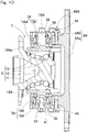
- a rotation-permitting support component 7A in the form of a tapered roller bearing is used, instead of the rotation-permitting support component 7 in the form of the spherical sliding bearing as shown in Fig. 1 .
- attachment shaft parts 19A each in the form of a trunnion shaft are provided on the outer ring 11 of the hub bearing 3 so as to protrude.
- Two of the attachment shaft parts 19A are provided on the upper and lower portions of the outer ring 11.
- Each of the attachment shaft part 19A in the form of the trunnion shaft has an outer periphery, to which an inner ring 15A of the rotation-permitting support component 7A in the form of the tapered roller bearing is fitted.
- An outer ring 16A of the rotation-permitting support component 7A is fitted to a fitting hole 38 provided in a unit support member 5A.
- the upper rotation-permitting support component 7A is formed with a male thread portion at a tip end (upper end) of the attachment shaft part 19A, and a nut 39 is screwed onto the male thread portion.
- the nut 39 presses the inner ring 15A in an axial direction (downwardly) of the attachment shaft part 19A.
- a pressing member 41 is fitted to the fitting hole 38 in the unit support member 5A, and a bolt 42 is screwed into a screw hole provided in a hollow part of the attachment shaft part 19A.
- the bolt 42 presses the end face of the outer ring 16A through the pressing member 41. Pressing by the nut 39 and the bolt 42 applies preload to the upper and lower rotation-permitting support components 7A, respectively, which are in the form of the tapered roller bearings.
- the unit support member 5A includes a main member 5Aa and divided bodies 5Ab provided for the respective rotation-permitting support components 7A, 7A, and the main member 5Aa and the divided bodies 5Ab are connected with each other by bolts 44.
- the unit support member 5A is attached to the knuckle 22 at the divided bodies 5Ab by use of bolts (not illustrated).
- the main member 5Aa, the divided bodies 5Ab and the bolt 43 cooperate together to constitute a preloading unit 48A.
- the upper and lower rotation-permitting support components 7A, 7A may have the same attachment structure to the unit support member 5A.
- the fixing structure of the upper rotation-permitting support component 7A to the unit support member 5A and the outer ring 11 of the hub bearing 3 as shown in Fig. 10 may be applied to the lower rotation-permitting support component 7A.
- the fixing structure of the lower rotation-permitting support component 7A may be used to fix the upper rotation-permitting support component 7A.
- a rotation-permitting support component 7A in the form of a tapered roller bearing preload can be applied to the rotation-permitting support component 7A, thereby to enhance rigidity.
- the rotation-permitting support component 7A may be an angular ball bearing or a four-point-contact ball bearing, instead of a tapered roller bearing. Even in such a case, preload can be applied in the same manner as described above. Since other features and effects of this embodiment are the same as those of the first embodiment, corresponding elements are denoted with like reference numerals, and the description thereof is not repeated.
- Fig.13 shows an example of the supplemental turning actuator 6.
- This supplemental turning actuator 6 may be applied either of the first and second embodiments.
- the driving force of the motor 27 is transmitted to a drive pulley 51 connected to a motor shaft 27a and then to a driven pulley 52 disposed in parallel with the motor shaft 27a through a belt 53.
- the drive pulley 51, the driven pulley 52 and the belt 53 cooperate together to constitute the winding-type speed reduction gear 28.
- the linear mechanism 29 is a feed screw mechanism.
- a nut 55 is provided on an inner periphery of the driven pulley 52 so as to integrally rotate with the driven pulley.
- a screw shaft 54 of the linear mechanism 29 is screwed into the nut 55.
- the nut 55 and the screw shaft 54 are a sliding screw and, specifically, have thread grooves and thread ridges that form thread portions 58 of a trapezoid screw with a self-locking function. Since the rotation of the nut 55 that integrally rotates with the driven pulley 52 prevents the screw shaft 54 from rotating by a locking part 56, the screw shaft 54 linearly moves forward and backward (axially).
- the supplemental turning force receiving part 18 provided to the outer ring 11 of the hub bearing 3 is coupled to the linear output part 29a at the tip end of the screw shaft 54 through the joint 57.
- the joint 57 is rotatably coupled to the supplemental turning force receiving part 18 and the linear output part 29a by two pins 57a. Therefore, thanks to the forward and backward movement of the screw shaft 54, the entirety of the hub unit body 4 including the hub bearing 3 can rotate about the supplemental turning axis A with respect to the unit support member 5 (5A).
- the driven pulley 52 and the nut 55 of the linear mechanism 29 are separately formed in this embodiment, the driven pulley 52 and the nut 55 may be integrally formed.
- Fig. 14 shows another example of the supplemental turning actuator 6.
- the supplemental turning actuator 6 shown in Fig. 14 may also be applied to either of the first and second embodiments.
- the driving force of the motor 27 is transmitted to a drive gear 59 connected to the motor shaft 27a and then to a driven gear 60 engaged with the drive gear 59.
- the drive gear 59 and the driven gear 60 cooperate together to constitute a gear train of the speed reduction gear 28.
- the linear mechanism 29 is in the form of the feed screw mechanism.
- the nut 55A is provided at the center of the driven gear 60 so as to integrally rotate with the driven gear 60.
- the screw shaft 54 of the linear mechanism 29 is screwed into the nut 55A.
- the configuration of the linear mechanism 29 and the coupling structure between the linear mechanism 29 and the hub unit body 4 are the same as those of the example shown in Fig. 13 . That is, the thread portions 58 of the nut 55A and the screw shaft 54 is a sliding screw or specifically, a trapezoid screw having a self-locking function.
- the supplemental turning force receiving part 18 provided to the outer ring 11 of the hub bearing 3 is coupled to the linear output part 29a at the tip end of the screw shaft 54 through the joint 57.
- the joint 57 is rotatably coupled to the supplemental turning force receiving part 18 and the linear output part 29a by two pins 57a. Therefore, thanks to the forward and backward movement of the screw shaft 54, the entirety of the hub unit body 4 including the hub bearing 3 can rotate about the supplemental turning axis A with respect to the unit support member 5.
- the driven gear 60 and the nut 55A of the linear mechanism 29 are integrally formed in this embodiment, the driven gear 60 and the nut 55 may be separate members that are connected with each other.
- the sliding screw having the self-locking function is used in the linear mechanism 29 also in this embodiment, as in the embodiment shown in Fig. 13 , the above-described effect of the self-locking function can be obtained. Additionally, in this embodiment, since the speed reduction gear 28 is formed of the gear train, highly-rigid and highly-responsive drive transmission can be performed.
Landscapes
- Engineering & Computer Science (AREA)
- Mechanical Engineering (AREA)
- Chemical & Material Sciences (AREA)
- Combustion & Propulsion (AREA)
- Transportation (AREA)
- General Engineering & Computer Science (AREA)
- Steering-Linkage Mechanisms And Four-Wheel Steering (AREA)
- Vehicle Body Suspensions (AREA)
- Power Steering Mechanism (AREA)
Abstract
Description
- This application claims Convention priority to Japanese patent application No.
2017-122997, filed June 23, 2017 - The present invention relates to a supplemental turning function-equipped hub unit having a function of performing additional turning to turning performed by a steering device and/or performing supplemental turning, such as rear wheel turning, and to a vehicle having such a supplemental turning function-equipped hub unit.
- In general, vehicles, such as automobiles, include a steering wheel mechanically connected with a steering device, the steering device having opposite ends connected to left and right wheels through tie rods. Therefore, a turning angle of the left and right wheels according to operation of the steering wheel is determined by an initial setting.
- Known vehicle geometries include: (1) "parallel geometry" in which left and right wheels have the same turning angle; and (2) "Ackermann geometry" in which a turning angle of an inner-ring tire is made larger than a turning angle of an outer-ring tire so as to have a single center of turning.
- The vehicle geometries influence stability of travelling.
- For example,
Patent Documents Patent Document 1, a knuckle arm and a joint position are relatively changed with each other, thereby to change the steering geometries. InPatent Document 2, two motors are used to allow both of a toe angle and a camber angle to be changed to any angle. In addition,Patent Document 3 discloses a mechanism for a four-wheel independent turning. - As a rear wheel steering device, a device that causes left and right rear wheels to turn in conjunction with each other so as to assist turning performed by the front wheels has been known (for example, Patent Document 4).
-
- [Patent Document 1]
JP Laid-open Patent Publication No. 2009-226972 - [Patent Document 2]
DE Patent Publication No. 102012206337 - [Patent Document 3]
JP Laid-open Patent Publication No. 2014-061744 - [Patent Document 4]
JP Laid-open Patent Publication No. 2016-147513 - In Ackermann geometry, a difference in turning angles of left and right wheels is set such that the respective wheels turn about a single common pint in order to smoothly turn the wheels in turning in a low-speed range where a centrifugal force acting on a vehicle is negligible. In contrast, in turning in a high-speed range where such a centrifugal force is not negligible, since it is desirable that the wheels generate a cornering force in a direction counterbalancing the centrifugal force, parallel geometry is preferred to Ackermann geometry.
- As mentioned above, since a turning device of a general vehicle is mechanically connected to wheels, the vehicle can only assume a single fixed steering geometry and is often arranged or set in an intermediate geometry between Ackermann geometry and parallel geometry. In such a case, however, the turning angle of the outer ring becomes excessively large in a low-speed range because the difference in turning angles of the left and right wheels is insufficient, whereas the turning angle of the inner ring becomes excessively large in a high-speed range. Thus, when distribution of a tire lateral force becomes unnecessarily unbalanced between inner and outer rings, travel resistance may be deteriorated, thereby causing worsening of fuel economy and early wear of the tire. Further, there is a problem that smooth cornering is deteriorated because the inner and outer rings cannot not be effectively used.
- Although the mechanisms disclosed in
Patent Documents - In
Patent Document 1, a knuckle arm and a joint position are relatively changed, thereby to change the steering geometries, as mentioned above. Change made at this location would only cause small change in the tire angles, and it is thus necessary to cause a large change, i.e., to largely move them, in order to obtain a large effect. It is extremely difficult to provide a motor actuator which can provide such a large force that the vehicle geometries can be changed in such a part, due to space constraints. - Since two motors are used in
Patent Document 2, the increased number of the motors results in increased costs and makes it complicated to control. - The mechanism disclosed in
Patent Document 3 can only be applied to four-wheel independent steering vehicles. In addition, since a hub bearing is supported in a cantilever manner with respect to a turning shaft, rigidity is reduced, and a steering geometry may be changed due to generation of excessive turning acceleration G. Where a speed reduction gear is provided on the turning shaft, a large power is required. However, where a larger motor is used to obtain such a large motor, it is difficult to dispose the entire motor in an inner peripheral part of a wheel. Where a speed reduction gear having a high reduction ratio is provided, responsibility is deteriorated. - As discussed above, a mechanism having a conventional supplemental turning function is intended to arbitrarily change a toe angle and a camber angle of a tire in a vehicle and thus has a complicated structure. In addition, it is difficult to ensure rigidity, and it is necessary to make the mechanism large in order to ensure rigidity, resulting in an increased weight.
- On the other hand, a rear wheel steering device has been known in which left and right rear wheels are caused to turn in conjunction with each other, as discussed above. However, such a device tends to be unable to perform independent turning of the left and right rear wheels and/or toe angle adjustment. In addition, where the device is capable of performing independent turning, the device may have a complicated configuration and/or may not be sufficiently strong.
- An object of the present invention is to provide a supplemental turning function-equipped hub unit that is capable of independently performing supplemental turning in left and right wheels in accordance with travel conditions, thereby improving motion performance of a vehicle to improve travel stability and fuel economy and has a simple and strong configuration, and to provide a vehicle including such a supplemental turning function-equipped hub unit.
- A supplemental turning function-equipped hub unit of the present invention includes: a hub unit body including a hub bearing configured to support a wheel; a unit support member configured to be mounted to a vehicle body through a suspension device, the unit support member supporting the hub unit body through rotation-permitting support components at two portions of upper and lower portions of the hub unit body such that the hub unit body is rotatable about a supplemental turning axis extending in a vertical direction or an up-and-down direction; and a supplemental turning force receiving part provided in a side part of the hub unit body, the supplemental turning force receiving part being configured to receive a force that causes the hub unit body to rotate about the supplemental turning axis.
- This configuration makes it possible to freely rotate the hub bearing that supports the wheel along with the hub unit body about the supplemental turning axis by the force applied from the supplemental turning force receiving part. This makes it possible to perform independent turning of a single wheel. Also, it is possible to arbitrarily change a toe angle of a tire in accordance with travel conditions of a vehicle. For these reasons, the supplemental turning function-equipped hub unit can be applied to either of a turning wheel (for example, a front wheel) and a non-turning wheel (for example, a rear wheel). Where the supplemental turning function-equipped hub unit is applied to a turning wheel, the hub unit can be provided to a member whose direction is changed by a steering device, thereby to cause a minute change in tire angles to left and right wheels in an individual manner or a linked manner, in addition to turning performed by steering operation by a driver.
- The tire angles of the left and right wheels can be independently and arbitrarily changed during travelling in accordance with travel conditions of the vehicle. This makes it possible to change steering geometries during travelling, for example, to assume parallel geometry when turning in a high-speed range and to assume Ackermann geometry when turning in a low-speed range. Therefore, motion performance of the vehicle can be improved, making it possible to drive stably. Additionally, a suitable tire angle can be set so as to improve fuel economy. Where the supplemental turning function-equipped hub unit is applied to a rear wheel (non-turning wheel), a minimum turning radius when travelling at low speed can be reduced.
- The supplemental turning function-equipped hub unit is supported by the rotation-permitting support components at two portions of upper and lower portions thereof so as to be rotatable about the supplemental turning axis. Thus, this arrangement of the hub unit being supported at both ends thereof ensures rigidity and achieves simple configuration. The supplemental turning function-equipped hub unit may be provided with, for example, a motor-driven actuator to apply a rotation force to the supplemental turning force receiving part. Thus, it is possible to independently perform supplemental turning in the left and right wheels in accordance with travel conditions and to arbitrarily change toe angles of the wheels, with simple configuration, while ensuring rigidity. Therefore, motion performance of the vehicle can be improved, making it possible to improve travel stability and fuel economy.
- The supplemental turning function-equipped hub unit of the present invention may include a supplemental turning actuator configured to apply a driving force, that causes the hub unit body to rotate about the supplemental turning axis, to the supplemental turning force receiving part. Where the supplemental turning actuator is provided, tire angles, such as toe angles, can be freely controlled in accordance with travel conditions.
- The supplemental turning axis may extend in the vertical direction. As long as the supplemental turning axis extends in a vertical direction or an up-and-down direction, it may be tilted to some extent. Where the axis extends in the vertical direction, it is possible to better suppress a change in a camber angle due to supplemental turning and to further suppress an increase in travel resistance. Further, where the axis extends in the vertical direction, it is easier to ensure a region for installing the unit support member in a limited space of a tire house.
- In the supplemental turning function-equipped hub unit of the present invention, the rotation-permitting support component may be a spherical sliding bearing. The term "spherical sliding bearing" used herein refers to bearings, including a spherical bush and a pivot bearing. Such a sliding bearing can accommodate inclination of a central axis of the rotation-permitting support component, even if the central axis is tilted with respect to the supplemental turning axis, because the spherical sliding bearing can rotate in any direction about a spherical center thereof. Therefore, it is possible to fix the hub unit in a different direction from that of the supplemental turning axis, which improves flexibility in mounting positions and makes it easier to process. Further, use of a spherical sliding bearing makes it possible to apply preload between a stationary-side component and a mobile-side component of the bearing through clamping when mounting the bearing, thereby to increase rigidity.
- In the supplemental turning function-equipped hub unit of the present invention, the rotation-permitting support component may be a tapered roller bearing, or an angular ball bearing, or a four-point-contact ball bearing. Since a tapered roller bearing, an angular ball bearing or a four-point-contact ball bearing can bear axial load, it is possible to apply preload to the bearing through clamping when mounting the bearing. Thus, the bearing can be supported without rattling due to inner gaps of the bearing, resulting in enhanced rigidity. Although a deep grooved ball bearing can also bear axial load to some extent, the above-mentioned bearings can bear larger axial load.
- A vehicle of the present invention includes one or both of front wheels and rear wheels that are supported by supplemental turning function-equipped hub units of the present invention. Therefore, the above effect of the supplemental turning function-equipped hub unit of the present invention can be obtained. Where supplemental turning function-equipped hub units of the present invention are applied to turning wheels (for example, front wheels), toe angle adjustment during travelling can be effectively performed. Where they are applied to non-turning wheels (for example, rear wheels), a minimum turning radius when travelling at low speed can be reduced, thanks to slight turning of the non-turning wheels.
- The present invention encompasses any combination of at least two features disclosed in the claims and/or the specification and/or the drawings. In particular, any combination of two or more of the appended claims should be equally construed as included within the scope of the present invention.
- The present invention will be more clearly understood from the following description of preferred embodiments thereof, when taken in conjunction with the accompanying drawings. However, the embodiments and the drawings are given only for the purpose of illustration and explanation, and are not to be taken as limiting the scope of the present invention in any way whatsoever, which scope is to be determined by the appended claims. In the accompanying drawings, like reference numerals are used to denote like parts throughout the several views.
-
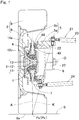
Fig. 1 is a longitudinal section view of a supplemental turning function-equipped hub unit according to a first embodiment of the present invention and surrounding features; -
Fig. 2 is a horizontal section view of the supplemental turning function-equipped hub unit and the surrounding features; -
Fig. 3 is a longitudinal section view of the supplemental turning function-equipped hub unit; -
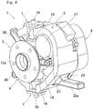
Fig. 4 is a perspective view illustrating an external appearance of the supplemental turning function-equipped hub unit; -
Fig. 5 is a left-side view of the supplemental turning function-equipped hub unit; -
Fig. 6 is a horizontal section view of the supplemental turning function-equipped hub unit in a main-turning neutral state; -
Fig. 7 is a horizontal section view of the supplemental turning function-equipped hub unit in a main-turning non-neutral state; -
Fig. 8 is a longitudinal section view of a supplemental turning function-equipped hub unit according to a second embodiment of the present invention and surrounding features; -
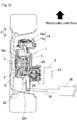
Fig. 9 is a horizontal section view of the supplemental turning function-equipped hub unit and the surrounding features; -
Fig. 10 is a longitudinal section view of the supplemental turning function-equipped hub unit; -
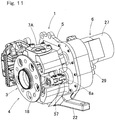
Fig. 11 is a perspective view illustrating an external appearance of the supplemental turning function-equipped hub unit; -
Fig. 12 is a left-side view of the supplemental turning function-equipped hub unit; -
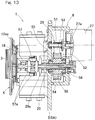
Fig. 13 is a horizontal section view illustrating a specific example of a supplemental turning actuator used in the first and second embodiments; -
Fig. 14 is a horizontal section view illustrating another specific example of a supplemental turning actuator used in the first and second embodiments; and -
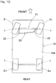
Fig. 15 is a schematic plan view illustrating an example of a vehicle to which a supplemental turning function-equipped hub unit according to the first and second embodiments is applied. - A first embodiment of the present invention will be described with reference to the drawings. As shown in
Fig. 1 , a supplemental turning function-equippedhub unit 1 includes: ahub unit body 4 including ahub bearing 3 for supporting awheel 2; aunit support member 5; and asupplemental turning actuator 6. Thehub unit body 4 is supported by theunit support member 5 through rotation-permittingsupport components wheel 2 and from a king pin axis K of main steering. Thewheel 2 includes awheel body 8 and atire 9. - The supplemental turning function-equipped
hub unit 1 of this embodiment is mounted to aknuckle 22 of a front wheel that is a turning wheel. Specifically, as shown inFig. 15 , the supplemental turning function-equippedhub unit 1 is operable to perform individual turning of each of the left andright wheels 2 by a minute angle, in addition to turning performed by asteering device 25 offront wheels 2F of avehicle 10. Thesteering device 25causes wheels hub unit 1 may be used for performing turning of each of therear wheels 2R to assist front wheel turning. - In
Fig. 1 , theunit support member 5 is mounted to aknuckle 22 of asuspension device 21 disposed in avehicle body 10A (Fig. 15 ). Theunit support member 5 may be provided integrally with theknuckle 22, i.e., as a part of theknuckle 22. Thesuspension device 21 of this embodiment is of a double wishbone type and includes anupper arm 23 and alower arm 24 connected with each other through a shock absorber (not illustrated). Theknuckle 22 is provided so as to be turnable about a king pin axis K that is tilted between tip ends of theupper arm 23 and thelower arm 24. Thesuspension device 21 is not limited to this configuration and may be of any known type, such as an independent suspension type. - As shown in
Fig. 2 , theknuckle 22 includes a steeringdevice coupling part 22a protruding radially outward of thewheel 2. The steeringdevice coupling part 22a is rotatably coupled with atie rod 26 of thesteering device 25. - As shown in
Fig. 3 , thehub bearing 3 includes: aninner ring 12; anouter ring 11; and rollingelements 13 interposed between the inner andouter rings elements 13 are, for example, balls. The hub bearing 3 couples a vehicle-body-side member and thewheel 2. Thehub bearing 3 of this embodiment is an angular ball bearing in which: theouter ring 11 is a fixed ring; theinner ring 12 is a rotary ring; and the rollingelements 13 are arranged in double rows. - The
inner ring 12 is constituted from two parts, i.e., ahub ring part 12a and aninner ring part 12b. Thehub ring part 12a includes a hub flange 12aa and forms a raceway surface on an outboard side. Theinner ring part 12b forms a raceway surface on an inboard side. Thewheel body 8 of thewheel 2 as shown inFig. 2 is fixed to the hub flange 12aa along with abrake rotor 14a by use of a bolt. Theinner ring 12 rotates about the rotation axis O. - The
brake rotor 14a and abrake caliper 14b cooperate together to constitute abrake 14 along with. Thebrake caliper 14b is attached to brakecaliper attachment parts 36 that are formed integrally with the outer ring 11 (seeFig. 3 ) in upper and lower portions of the outer ring so as to protrude in an arm-like manner, as shown inFig. 4 ,Fig. 5 . - In
Fig. 3 , thehub unit body 4 is a part of the supplemental turning function-equippedhub unit 1, which part rotates about the supplemental turning axis A. Thehub unit body 4 includes: thehub bearing 3; a rotary-side component 15 of the rotation-permittingsupport component 7; and a supplemental turning force receiving part 18 (seeFig. 2 ,Fig. 4 ). - The rotation-permitting
support component 7 in this embodiment includes a spherical sliding bearing and the rotary-side component 15 having a recessedspherical seat 15a and a stationary-side component 16. The term "spherical sliding bearing" used herein refers to bearings, including a spherical bush and a pivot bearing. The stationary-side component 16 includes aspherical part 16a fitted to the recessedspherical seat 15a so as to be rotatable in any direction and ashaft part 16b having a tip end formed with thespherical part 16a. The recessedspherical seat 15a is covered by aflexible bellow boot 17 covering an outer periphery of theshaft part 16b. - Attachment seats 19 having a cylindrical shape are provided on an outer peripheral surface of the
outer ring 11 of thehub bearing 3. The attachment seats 19 protrude radially outward from the outer peripheral surface of theouter ring 11. The attachment seats 19 are provided at upper and lower portions of the outer peripheral surface ofouter ring 11. The rotary-side component 15 of each of the upper and lower rotation-permittingsupport component 7 is attached to each of the upper and lower attachment seats 19, 19 in a fitted manner. - The stationary-
side component 16 of the rotation-permittingsupport component 7 is attached to theunit support member 5 such that preload applied to the rotation-permittingsupport component 7 can be adjusted by apreload adjusting unit 48. Theunit support member 5 includes asupport member body 5a fixed to theknuckle 22 and separatedsupport pieces 5b that are position-adjustable with respect to thesupport member body 5a in a direction along the supplemental turning axis A. Thesupport pieces 5b are position-adjustable with respect to thesupport member body 5a by fastening of anadjustment bolt 49. Thesupport member body 5a, thesupport pieces 5b and theadjustment bolt 49 cooperate together to constitute thepreload adjusting unit 48. - In this embodiment, the
outer ring 11 of thehub bearing 3 is integrally formed with the attachment seats 19, and the rotary-side component 15 of the rotation-permittingsupport component 7 is directly attached to theouter ring 11, as described above. However, a mounting part (not illustrated), such as an axle box, may be provided on the outer periphery of theouter ring 11 so that the rotary-side component 15 of the rotation-permittingsupport component 7 is attached to the mounting part. - As shown in
Fig. 1 , in this embodiment, a direction of the supplemental turning axis A of thehub unit body 4 differs from a direction of the king pin axis K, and corresponds to the vertical direction. In this embodiment, the supplemental turning axis A is defined such that both of "an intersection position PK of an extension line of the king pin axis K and a road surface S" and "an intersection position PA of an extension line of the supplemental turning axis A and the road surface S" are located on atire grounding surface 9a. Further, where the intersection positions PK, PA coincide with each other, slipping of the tire is minimized. Thus, it is preferable that the intersection positions PK, PA coincide with each other. The term "tire grounding surface" used herein refers to an area where thetire 9 is in contact with the road surface S in a state where a passenger (approximately 55 kg) is seated on the driver's seat. - The supplemental turning
force receiving part 18 as shown inFig. 2 ,Fig. 4 is a part that acts as a point of application where a supplemental turning force is applied to theouter ring 11 of thehub bearing 3. The supplemental turningforce receiving part 18 is provided as an arm part that is integrally formed with a part of the outer periphery of theouter ring 11 of thehub bearing 3 so as to protrude. The supplemental turningforce receiving part 18 is rotatably coupled with alinear output part 6a of thesupplemental turning actuator 6 through a joint 57, as discussed later with reference toFig. 13 . Thus, when thelinear output part 6a of thesupplemental turning actuator 6 advances or retracts, thehub unit body 4 rotates about the supplemental turning axis A. That is, thehub unit body 4 is caused to perform supplemental turning. - The
supplemental turning actuator 6 includes: a motor 27 (Fig. 3 ); a speed reduction gear 28 (as shown inFig. 2 ) which reduces a speed of rotation of themotor 27; and alinear mechanism 29 which converts normal and reverse rotation outputs of thespeed reduction gear 28 into reciprocating linear motion of thelinear output part 6a. Themotor 27 is, for example, a permanent magnet synchronous motor. Themotor 27, however, is not limited to this and may be a direct current motor or an induction motor. - The
speed reduction gear 28 may be a winding-type transmission mechanism, such as a belt transmission mechanism, or a gear train. InFig. 2 , a belt transmission mechanism is used as thespeed reduction gear 28. Thelinear mechanism 29 may be a feed screw mechanism, such as a sliding screw and a ball screw, or a rack and pinion mechanism. In this embodiment, a feed screw mechanism with a trapezoid sliding screw is used as thelinear mechanism 29. - Although the
supplemental turning actuator 6 includes thespeed reduction gear 28 in this embodiment, thesupplemental turning actuator 6 may have nospeed reduction gear 28 and be configured such that a driving force of themotor 27 is directly transmitted to thelinear mechanism 29. Alternatively, thesupplemental turning actuator 6 may have nomotor 27. In such a case, thesupplemental turning actuator 6 may be, for example, an actuator that is driven by hydraulic pressure. - An angle θ (
Fig. 6 ,Fig. 7 ) of supplemental turning with respect to theknuckle 22 of thehub unit body 4 is limited by astopper 35.Fig. 6 shows a situation where main turning is performed in a straight forward manner and supplemental turning is performed inwardly.Fig. 7 shows a situation where main turning is performed to the left and supplemental turning is performed inwardly. Thestopper 35 is provided, for example, on a surface of theunit support member 5, which surface axially confronts thehub unit body 4, or, for example, on a surface of thehub bearing 3, which surface confronts an end face of theouter ring 11. The end face of theouter ring 11 of thehub bearing 3 abuts with thestopper 35, whereby the angle θ of supplemental turning of thehub unit body 4 is limited. An acceptable range of a supplementally turnable angle of thehub unit body 4 may be a small angle range. The acceptable range of the supplementally turnable angle limited by thestopper 35 may be, for example, ±5 degrees or smaller. - In this embodiment, the
outer ring 11 of thehub bearing 3 is integrally formed with the attachment seat 19 (Fig. 3 ,Fig. 4 ) to which the rotation-permittingsupport components 7 are attached, the supplemental turning force receiving part 18 (Fig. 2 ,Fig. 4 ) and the brakecaliper attachment parts 36. It should be noted that as long as theattachment seat 19, the supplemental turningforce receiving part 18 and the brakecaliper attachment parts 36 are provided on thehub unit body 4, they may be provided in a mounting part (not illustrated), such as an axle box, which may be provided to theouter ring 11. - The above features are described in terms of operation and effects. The supplemental turning function-equipped
hub unit 1 is configured such that thehub unit body 4 including thehub bearing 3 and thebrake caliper 14b (seeFig. 2 ) is rotatable about the supplemental turning axis A with respect to theunit support member 5 provided to theknuckle 22 inFig. 1 . That is, a force is applied to the arm-like supplemental turning force receiving part 18 (Fig. 2 ) that acts as a point of application, whereby thehub unit body 4 can be rotated. Thelinear output part 6a of thesupplemental turning actuator 6 provided to theunit support member 5 advances or retracts by driving themotor 27, whereby thehub unit body 4 is rotated through the supplemental turningforce receiving part 18 coupled to thelinear output part 6a. - This rotation is performed as supplemental turning in addition to turning performed by steering operation by a driver, i.e., in addition to the rotation of the
knuckle 22 about the king pin axis K (Fig. 1 ) caused by thesteering device 25. The supplemental turning is also performed as independent turning of a single wheel. The left andright wheels right wheels - Since the tire angles of the left and right wheels can be independently and arbitrarily changed during travelling in accordance with travel conditions of the
vehicle 10, motion performance of thevehicle 10 can be improved, making it possible to drive stably. Additionally, a suitable tire angle can be set so as to improve fuel economy. Where the supplemental turning function-equippedhub units 1 are applied to therear wheels 2R (Fig. 15 ) that are non-turning wheels, a minimum turning radius when travelling at low speed can be reduced. - The supplemental turning function-equipped
hub unit 1 is supported by the rotation-permittingsupport components wheels 2, thereby to change the steering geometries. Therefore, motion performance of thevehicle 10 is improved, making it possible to improve both of travel stability and fuel economy. - An example of the turning-angle difference control of the left and right wheels in accordance with travelling speed will be described. Since a turning device of a general vehicle is mechanically connected to wheels, the vehicle can only assume a single fixed steering geometry and is often arranged or set in an intermediate geometry between Ackermann geometry and parallel geometry. In such a case, the turning angle of the outer ring becomes excessively large in a low-speed range because the difference in turning angles of the left and right wheels is insufficient, whereas the turning angle of the inner ring becomes excessively large in a high-speed range. Thus, when distribution of a tire lateral force becomes unnecessarily unbalanced between inner and outer rings, travel resistance may be deteriorated, causing worsening of fuel economy and early wear of the tire. Further, smooth cornering is deteriorated because the inner and outer rings cannot not be effectively used.
- Since the supplemental turning function-equipped
hub unit 1 of this embodiment can individually control the left andright wheels 2, the turning angles or steering angle of thewheels 2 can be changed in accordance with vehicle speed and/or turning acceleration G. Specifically, arbitrary selection between Ackermann geometry (in which difference in turning angles of the left and right wheels is set such that the respective wheels rotate about a single common point) in a low-speed range and parallel geometry (in which the turning angles of the left and right wheels are the same) in a high-speed range prevents an increase in travel resistance. Furthermore, this makes it possible to achieve both of smooth turnability at low speed and cornering performance at high speed. - As long as the supplemental turning axis A substantially extends in the vertical direction, it may be tilted to some extent. In this embodiment, the axis A extends in the vertical direction. This makes it possible to better suppress a change in a camber angle due to supplemental turning and to further suppress an increase in travel resistance. Where the king pin axis K and the supplemental turning axis A coincide with each other, supplemental turning of the
hub unit body 4 at the king pin axis K causes a large change in the camber angle and increases travel resistance. Separately defining the supplemental turning axis A from the king pin axis K makes it possible to suppress a change in the camber angle due to supplemental turning and to suppress an increase in travel resistance. - Also, where the king pin axis K and the supplemental turning axis A coincide with each other, components are arranged on the vehicle body side in the
hub unit body 4, resulting in an increased size and an increased weight as a whole. Defining the supplemental turning axis A in a different direction from that of the king pin axis K of thesuspension device 21 makes it possible to reduce the size of the entire device and to reduce the weight. - Further, since both of "the intersection position PK of the extension line of the king pin axis K of the
suspension device 21 and the road surface S" and "the intersection position PA of the extension line of the supplemental turning axis A and the road surface S" are located within thetire grounding surface 9a, both of main turning and supplemental turning can be stably and effectively performed. - Where the king pin axis K and the supplemental turning axis A are different from each other, if a point on the both extension lines of the axes is different from a grounding location of the
tire 9, slipping may occur when both of them move at the same time. This is inefficient and may disturb vehicle behavior. For this reason, it is desirable that "the intersection position PK of the extension line of the king pin axis K and the road surface S" and "the intersection position PA of the extension line of the supplemental turning axis A and the road surface S" are provided adjacent to each other. The two intersection positions PA, PK preferably coincide with each other. This allows main turning and supplemental turning to be effectively performed without causing slipping, even when main turning and supplemental turning are simultaneously performed, whereby the vehicle can be stably operated. - The angle of supplemental turning can be a small angle in order to improve motion performance of the vehicle and to improve travel stability. Specifically, the supplementally turnable angle may be ±5 degree or smaller. The angle of supplemental turning is adjusted through control performed by the
supplemental turning actuator 6. It should be noted that since the angle of supplemental turning is limited by thestopper 35, a large influence is avoided even when a failure occurs in the supplemental turning function-equippedhub unit 1 due to, e.g., a failure of a power supply system. Thus, the vehicle can be pulled over to a safe place by steering operation. - Since the rotation-permitting
support component 7 of this embodiment is a spherical sliding bearing, it can rotate in any direction about a spherical center thereof and accommodate inclination of a central axis of the rotation-permittingsupport component 7, even if the central axis is tilted with respect to the supplemental turning axis A. Therefore, the spherical sliding bearing makes it possible to fix thehub unit body 4 in a different direction from that of the supplemental turning axis A, which improves flexibility in mounting positions and makes it easier to process. Further, use of spherical sliding bearing makes it possible to apply preload between a stationary-side component 16 and a mobile-side component 15 of the bearing through clamping when mounting the bearing, thereby to increase rigidity. -
Fig. 8 to Fig. 12 show a second embodiment of the present invention. In this embodiment, a rotation-permittingsupport component 7A in the form of a tapered roller bearing is used, instead of the rotation-permittingsupport component 7 in the form of the spherical sliding bearing as shown inFig. 1 . As shown inFig. 10 ,attachment shaft parts 19A each in the form of a trunnion shaft are provided on theouter ring 11 of thehub bearing 3 so as to protrude. Two of theattachment shaft parts 19A are provided on the upper and lower portions of theouter ring 11. Each of theattachment shaft part 19A in the form of the trunnion shaft has an outer periphery, to which aninner ring 15A of the rotation-permittingsupport component 7A in the form of the tapered roller bearing is fitted. Anouter ring 16A of the rotation-permittingsupport component 7A is fitted to afitting hole 38 provided in aunit support member 5A. - The upper rotation-permitting
support component 7A is formed with a male thread portion at a tip end (upper end) of theattachment shaft part 19A, and anut 39 is screwed onto the male thread portion. Thenut 39 presses theinner ring 15A in an axial direction (downwardly) of theattachment shaft part 19A. In the lower rotation-permittingsupport component 7A, a pressingmember 41 is fitted to thefitting hole 38 in theunit support member 5A, and abolt 42 is screwed into a screw hole provided in a hollow part of theattachment shaft part 19A. Thebolt 42 presses the end face of theouter ring 16A through the pressingmember 41. Pressing by thenut 39 and thebolt 42 applies preload to the upper and lower rotation-permittingsupport components 7A, respectively, which are in the form of the tapered roller bearings. - The
unit support member 5A includes a main member 5Aa and divided bodies 5Ab provided for the respective rotation-permittingsupport components bolts 44. Theunit support member 5A is attached to theknuckle 22 at the divided bodies 5Ab by use of bolts (not illustrated). The main member 5Aa, the divided bodies 5Ab and the bolt 43 cooperate together to constitute apreloading unit 48A. - The upper and lower rotation-permitting
support components unit support member 5A. For example, the fixing structure of the upper rotation-permittingsupport component 7A to theunit support member 5A and theouter ring 11 of thehub bearing 3 as shown inFig. 10 may be applied to the lower rotation-permittingsupport component 7A. Alternatively, the fixing structure of the lower rotation-permittingsupport component 7A may be used to fix the upper rotation-permittingsupport component 7A. - Thus, even where a rotation-permitting
support component 7A in the form of a tapered roller bearing is provided, preload can be applied to the rotation-permittingsupport component 7A, thereby to enhance rigidity. The rotation-permittingsupport component 7A may be an angular ball bearing or a four-point-contact ball bearing, instead of a tapered roller bearing. Even in such a case, preload can be applied in the same manner as described above. Since other features and effects of this embodiment are the same as those of the first embodiment, corresponding elements are denoted with like reference numerals, and the description thereof is not repeated. -
Fig.13 shows an example of thesupplemental turning actuator 6. Thissupplemental turning actuator 6 may be applied either of the first and second embodiments. The driving force of themotor 27 is transmitted to a drivepulley 51 connected to amotor shaft 27a and then to a drivenpulley 52 disposed in parallel with themotor shaft 27a through abelt 53. Thedrive pulley 51, the drivenpulley 52 and thebelt 53 cooperate together to constitute the winding-typespeed reduction gear 28. - The
linear mechanism 29 is a feed screw mechanism. Anut 55 is provided on an inner periphery of the drivenpulley 52 so as to integrally rotate with the driven pulley. Ascrew shaft 54 of thelinear mechanism 29 is screwed into thenut 55. Thenut 55 and thescrew shaft 54 are a sliding screw and, specifically, have thread grooves and thread ridges that formthread portions 58 of a trapezoid screw with a self-locking function. Since the rotation of thenut 55 that integrally rotates with the drivenpulley 52 prevents thescrew shaft 54 from rotating by a lockingpart 56, thescrew shaft 54 linearly moves forward and backward (axially). - The supplemental turning
force receiving part 18 provided to theouter ring 11 of thehub bearing 3 is coupled to thelinear output part 29a at the tip end of thescrew shaft 54 through the joint 57. The joint 57 is rotatably coupled to the supplemental turningforce receiving part 18 and thelinear output part 29a by twopins 57a. Therefore, thanks to the forward and backward movement of thescrew shaft 54, the entirety of thehub unit body 4 including thehub bearing 3 can rotate about the supplemental turning axis A with respect to the unit support member 5 (5A). Although the drivenpulley 52 and thenut 55 of thelinear mechanism 29 are separately formed in this embodiment, the drivenpulley 52 and thenut 55 may be integrally formed. - Thus, where a sliding screw having a self-locking function is used in the
linear mechanism 29, reverse input from the tire is prevented. Also, in the event of a failure of themotor 27, the self-locking function prevents thetire 9 from staggering, and the vehicle can be pull over to a safe place by steering operation. Where thelinear mechanism 29 has the self-locking function, in the case where supplemental turning is not performed or when travelling at high speed, a fixed angle of supplemental turning can be maintained. This can eliminate the necessity of driving themotor 27 to maintain a fixed angle, thereby to reduce motor power. -
Fig. 14 shows another example of thesupplemental turning actuator 6. Thesupplemental turning actuator 6 shown inFig. 14 may also be applied to either of the first and second embodiments. The driving force of themotor 27 is transmitted to adrive gear 59 connected to themotor shaft 27a and then to a drivengear 60 engaged with thedrive gear 59. Thedrive gear 59 and the drivengear 60 cooperate together to constitute a gear train of thespeed reduction gear 28. - The
linear mechanism 29 is in the form of the feed screw mechanism. Thenut 55A is provided at the center of the drivengear 60 so as to integrally rotate with the drivengear 60. Thescrew shaft 54 of thelinear mechanism 29 is screwed into thenut 55A. The configuration of thelinear mechanism 29 and the coupling structure between thelinear mechanism 29 and thehub unit body 4 are the same as those of the example shown inFig. 13 . That is, thethread portions 58 of thenut 55A and thescrew shaft 54 is a sliding screw or specifically, a trapezoid screw having a self-locking function. When thenut 55 that integrally rotates with the drivenpulley 52 rotates, thescrew shaft 54 linearly moves forward and backward since thescrew shaft 54 is prevented from rotating by a lockingpart 56. - The supplemental turning
force receiving part 18 provided to theouter ring 11 of thehub bearing 3 is coupled to thelinear output part 29a at the tip end of thescrew shaft 54 through the joint 57. The joint 57 is rotatably coupled to the supplemental turningforce receiving part 18 and thelinear output part 29a by twopins 57a. Therefore, thanks to the forward and backward movement of thescrew shaft 54, the entirety of thehub unit body 4 including thehub bearing 3 can rotate about the supplemental turning axis A with respect to theunit support member 5. - Although the driven
gear 60 and thenut 55A of thelinear mechanism 29 are integrally formed in this embodiment, the drivengear 60 and thenut 55 may be separate members that are connected with each other. - Since the sliding screw having the self-locking function is used in the
linear mechanism 29 also in this embodiment, as in the embodiment shown inFig. 13 , the above-described effect of the self-locking function can be obtained. Additionally, in this embodiment, since thespeed reduction gear 28 is formed of the gear train, highly-rigid and highly-responsive drive transmission can be performed. - Although the present invention has been described in terms of the preferred embodiments thereof with reference to the drawings, the present invention is not limited to the above embodiments, and various additions, modifications, or deletions may be made without departing from the scope of the invention. Accordingly, such variants are included within the scope of the present invention.
-
- 1 ····
- Supplemental turning function-equipped hub unit
- 2 ····
- Wheel
- 3 ····
- Hub bearing
- 4 ····
- Hub unit body
- 5 ····
- Unit support member
- 5A ····
- Unit support member
- 6 ····
- Supplemental turning actuator
- 6a ····
- Linear output part
- 7 ····
- Rotation-permitting support component
- 7A ····
- Rotation-permitting support component
- 9 ····
- Tire
- 9a ····
- Tire grounding surface
- 10 ····
- Vehicle
- 10A ····
- Vehicle body
- 11 ····
- Outer ring
- 12 ····
- Inner ring
- 13 ····
- Rolling element
- 14a ····
- Brake rotor
- 14b ····
- Brake caliper
- 15 ····
- Rotary-side component
- 16 ····
- Stationary-side component
- 18 ····
- Supplemental turning force receiving part
- 21 ····
- Suspension device
- 22 ····
- Knuckle
- 25 ····
- Steering device
- 26 ····
- Tie rod
- 27 ····
- Motor
- 28 ····
- Speed reduction gear
- 29 ····
- Linear mechanism
- 35 ····
- Stopper
- 36 ····
- Brake caliper attachment part
- 48, 48A ····
- Preloading unit
- 51 ····
- Drive pulley
- 52 ····
- Driven pulley
- 53 ····
- Bolt
- 54 ····
- Screw shaft
- 55 ····
- Nut
- 56 ····
- Locking part
- 57 ····
- Joint
- 57a ····
- Pin
- 58 ····
- Thread portion
- 59 ····
- Drive gear
- 60 ····
- Driven gear
- A ···· ····
- Supplemental turning axis
- K ····
- King pin axis
- O ····
- Rotation axis
- PK ····
- Intersection position
- PA ····
- Intersection position
- S ····
- Road surface
- θ ····
- Angle of supplemental turning
Claims (6)
- A supplemental turning function-equipped hub unit comprising:a hub unit body including a hub bearing configured to support a wheel;a unit support member configured to be mounted to a vehicle body through a suspension device, the unit support member supporting the hub unit body through rotation-permitting support components at two portions of upper and lower portions of the hub unit body such that the hub unit body is rotatable about a supplemental turning axis extending in a vertical direction; anda supplemental turning force receiving part provided in a side part of the hub unit body, the supplemental turning force receiving part being configured to receive a force that causes the hub unit body to rotate about the supplemental turning axis.
- The supplemental turning function-equipped hub unit as claimed in claim 1, further comprising a supplemental turning actuator configured to apply a driving force, that causes the hub unit body to rotate about the supplemental turning axis, to the supplemental turning force receiving part.
- The supplemental turning function-equipped hub unit as claimed in claim 1 or 2, wherein the supplemental turning axis extends in the vertical direction.
- The supplemental turning function-equipped hub unit as claimed in any one of claims 1 to 3, wherein each of the rotation-permitting support components includes a spherical sliding bearing.
- The supplemental turning function-equipped hub unit as claimed in any one of claims 1 to 3, wherein each of the rotation-permitting support components is a tapered roller bearing, or an angular ball bearing, or a four-point-contact ball bearing.
- A vehicle comprising supplemental turning function-equipped hub units as claimed in any one of claims 1 to 5,
wherein one or both of front wheels and rear wheels are supported by the supplemental turning function-equipped hub unit.
Applications Claiming Priority (2)
| Application Number | Priority Date | Filing Date | Title |
|---|---|---|---|
| JP2017122997A JP6909071B2 (en) | 2017-06-23 | 2017-06-23 | Hub unit with auxiliary steering function and vehicle |
| PCT/JP2018/023592 WO2018235894A1 (en) | 2017-06-23 | 2018-06-21 | Hub unit with auxiliary steering function and vehicle |
Publications (2)
| Publication Number | Publication Date |
|---|---|
| EP3643584A1 true EP3643584A1 (en) | 2020-04-29 |
| EP3643584A4 EP3643584A4 (en) | 2021-03-03 |
Family
ID=64737631
Family Applications (1)
| Application Number | Title | Priority Date | Filing Date |
|---|---|---|---|
| EP18820501.7A Withdrawn EP3643584A4 (en) | 2017-06-23 | 2018-06-21 | HUB UNIT AND VEHICLE EQUIPPED WITH AN ADDITIONAL TURNING FUNCTION |
Country Status (5)
| Country | Link |
|---|---|
| US (1) | US11097768B2 (en) |
| EP (1) | EP3643584A4 (en) |
| JP (1) | JP6909071B2 (en) |
| CN (1) | CN110785336B (en) |
| WO (1) | WO2018235894A1 (en) |
Cited By (2)
| Publication number | Priority date | Publication date | Assignee | Title |
|---|---|---|---|---|
| EP3778355A4 (en) * | 2018-03-27 | 2021-12-22 | NTN Corporation | Hub unit with steering function, steering system, and vehicle |
| US12097911B2 (en) | 2018-03-27 | 2024-09-24 | Ntn Corporation | Steering system and vehicle equipped with same |
Families Citing this family (9)
| Publication number | Priority date | Publication date | Assignee | Title |
|---|---|---|---|---|
| JP6567633B2 (en) * | 2017-11-28 | 2019-08-28 | Ntn株式会社 | Hub unit with steering function and vehicle equipped with the same |
| JP7182455B2 (en) * | 2018-12-20 | 2022-12-02 | Ntn株式会社 | HUB UNIT WITH STEERING FUNCTION AND VEHICLE INCLUDING THE SAME |
| JP7320468B2 (en) | 2020-03-10 | 2023-08-03 | Ntn株式会社 | HUB UNIT WITH STEERING FUNCTION AND VEHICLE INCLUDING THE SAME |
| KR20220134860A (en) * | 2021-03-29 | 2022-10-06 | 현대자동차주식회사 | Steering shock absorbing structure and method for in-wheel motor |
| US12017499B2 (en) * | 2021-05-25 | 2024-06-25 | Hyundai Mobis Co., Ltd. | Suspension device for in-wheel motor |
| AU2021103311B4 (en) * | 2021-06-11 | 2022-09-22 | Titan Design & Engineering Pty Ltd | Camber adjustment system |
| US12409692B2 (en) * | 2022-02-03 | 2025-09-09 | Hyundai Mobis Co., Ltd. | Corner module apparatus for vehicle |
| US12319107B2 (en) * | 2023-06-07 | 2025-06-03 | GM Global Technology Operations LLC | Vehicle ride height adjustment system |
| US12485965B1 (en) | 2024-12-23 | 2025-12-02 | Dana Graziano S.R.L. | Active wheel carrier system and method |
Family Cites Families (31)
| Publication number | Priority date | Publication date | Assignee | Title |
|---|---|---|---|---|
| US5027275A (en) * | 1987-11-30 | 1991-06-25 | Mazda Motor Corporation | Method for toe angle adjustment for a vehicle and a toe angle adjusting apparatus therefor |
| NO175016C (en) * | 1992-04-03 | 1994-08-17 | Arne Aarre | Apparatus for establishing a pivotal coupling of two relatively pivotal parts |
| DE19836440A1 (en) * | 1998-08-12 | 2000-02-24 | Daimler Chrysler Ag | Wheel suspension for motor vehicles, in particular independent wheel suspension for passenger cars |
| JP2000174219A (en) * | 1998-12-01 | 2000-06-23 | Rohm Co Ltd | Ferroelectric memory device and its manufacture |
| DE19900082C2 (en) * | 1999-01-04 | 2003-09-25 | Continental Ag | Friction control system and pneumatic vehicle tires with sensor for it |
| JP4298529B2 (en) * | 2004-01-29 | 2009-07-22 | Ntn株式会社 | Fixed type constant velocity universal joint |
| JP2007055538A (en) * | 2005-08-26 | 2007-03-08 | Ntn Corp | Suspension device supporting structure |
| JP4380640B2 (en) * | 2006-02-09 | 2009-12-09 | トヨタ自動車株式会社 | Vehicle stabilizer system |
| JP4244999B2 (en) * | 2006-02-09 | 2009-03-25 | トヨタ自動車株式会社 | Vehicle stabilizer system |
| SE0701358L (en) * | 2007-06-01 | 2008-10-07 | Skf Ab | A bearing component for a rolling bearing or a sliding bearing |
| DE102007054823A1 (en) * | 2007-11-16 | 2009-05-20 | Audi Ag | Adjustment device for wheel suspensions |
| EP2241462A4 (en) * | 2008-02-07 | 2012-10-03 | Equos Res Co Ltd | CONTROL DEVICE AND VEHICLE |
| JP5144304B2 (en) * | 2008-02-22 | 2013-02-13 | 本田技研工業株式会社 | Vehicle rear wheel steering device |
| JP2009226972A (en) * | 2008-03-19 | 2009-10-08 | Fuji Heavy Ind Ltd | Geometry varying device |
| CN201249804Y (en) * | 2008-08-19 | 2009-06-03 | 一拖(洛阳)开创装备科技有限公司 | Master pin adjusting-free device for steering driving axle |
| DE102009006903A1 (en) | 2009-01-30 | 2010-08-05 | Audi Ag | Device for adjusting the camber and / or track of the wheels of wheel suspensions |
| DE102009033105B4 (en) * | 2009-07-15 | 2021-03-25 | Audi Ag | Adjusting device for wheel suspensions of motor vehicles |
| WO2012140963A1 (en) * | 2011-04-13 | 2012-10-18 | 日産自動車株式会社 | Lubrication control device for in-wheel motor unit for vehicle |
| US8876390B2 (en) * | 2011-12-14 | 2014-11-04 | Roller Bearing Company Of America, Inc. | Slotted bearings with wear-resistant treatments for gearbox mounting in a geared turbofan engine |
| DE102012206337B4 (en) * | 2012-04-18 | 2020-01-23 | Schaeffler Technologies AG & Co. KG | Device for a wheel suspension of a two-lane vehicle |
| JP2014061744A (en) * | 2012-09-20 | 2014-04-10 | Jtekt Corp | Steering device and vehicle |
| DE102014205145A1 (en) * | 2014-03-19 | 2015-09-24 | Bayerische Motoren Werke Aktiengesellschaft | Independent suspension of a steerable by means of an actuator rear wheel of a vehicle |
| JP6382597B2 (en) * | 2014-06-27 | 2018-08-29 | Ntn株式会社 | vehicle |
| JP2016147513A (en) * | 2015-02-10 | 2016-08-18 | Ntn株式会社 | Rear wheel steering device |
| JP2017122997A (en) | 2016-01-06 | 2017-07-13 | 富士通株式会社 | Information processing unit, control method for arithmetic processing unit, and control program for arithmetic processing unit |
| DE102017208554A1 (en) * | 2017-05-19 | 2018-11-22 | Bayerische Motoren Werke Aktiengesellschaft | Wheel suspension for an at least slightly actively steerable rear wheel of a two-lane vehicle, axle with a suspension and vehicle with a suspension |
| JP7025175B2 (en) * | 2017-10-17 | 2022-02-24 | Ntn株式会社 | Vehicle power unit |
| JP6605010B2 (en) * | 2017-11-27 | 2019-11-13 | 本田技研工業株式会社 | Wheel steering device |
| JP6567633B2 (en) * | 2017-11-28 | 2019-08-28 | Ntn株式会社 | Hub unit with steering function and vehicle equipped with the same |
| JP7202930B2 (en) * | 2018-03-20 | 2023-01-12 | Ntn株式会社 | Steering system and vehicle equipped with it |
| LU101110B1 (en) * | 2019-01-29 | 2020-07-29 | Alpha Ec Ind 2018 S A R L | Low platform bus with steering modules |
-
2017
- 2017-06-23 JP JP2017122997A patent/JP6909071B2/en active Active
-
2018
- 2018-06-21 WO PCT/JP2018/023592 patent/WO2018235894A1/en not_active Ceased
- 2018-06-21 EP EP18820501.7A patent/EP3643584A4/en not_active Withdrawn
- 2018-06-21 CN CN201880041374.4A patent/CN110785336B/en not_active Expired - Fee Related
-
2019
- 2019-12-19 US US16/721,519 patent/US11097768B2/en not_active Expired - Fee Related
Cited By (3)
| Publication number | Priority date | Publication date | Assignee | Title |
|---|---|---|---|---|
| EP3778355A4 (en) * | 2018-03-27 | 2021-12-22 | NTN Corporation | Hub unit with steering function, steering system, and vehicle |
| US11731693B2 (en) | 2018-03-27 | 2023-08-22 | Ntn Corporation | Hub unit with steering function, steering system, and vehicle |
| US12097911B2 (en) | 2018-03-27 | 2024-09-24 | Ntn Corporation | Steering system and vehicle equipped with same |
Also Published As
| Publication number | Publication date |
|---|---|
| US20200122771A1 (en) | 2020-04-23 |
| JP6909071B2 (en) | 2021-07-28 |
| US11097768B2 (en) | 2021-08-24 |
| WO2018235894A1 (en) | 2018-12-27 |
| CN110785336A (en) | 2020-02-11 |
| EP3643584A4 (en) | 2021-03-03 |
| JP2019006228A (en) | 2019-01-17 |
| CN110785336B (en) | 2022-07-15 |
Similar Documents
| Publication | Publication Date | Title |
|---|---|---|
| US11097768B2 (en) | Supplemental turning function-equipped hub unit and vehicle | |
| US11731693B2 (en) | Hub unit with steering function, steering system, and vehicle | |
| WO2018235892A1 (en) | Hub unit with auxiliary steering function and vehicle | |
| EP3689711B1 (en) | Hub unit equipped with steering function, and vehicle provided with same | |
| JP6899465B2 (en) | Hub bearing with steering shaft and vehicle equipped with it | |
| US20210362770A1 (en) | Hub unit having steering function, and vehicle equipped with same | |
| WO2018235891A1 (en) | Hub unit with auxiliary steering function and vehicle | |
| WO2018235893A1 (en) | Hub unit with auxiliary steering function and vehicle | |
| EP4119423A1 (en) | Hub unit having steering function, and vehicle equipped with same | |
| JP6990078B2 (en) | Hub unit with steering function and vehicles equipped with it | |
| JP2020097280A (en) | Hub unit with steering function and steering system | |
| JP2019051846A (en) | Hub unit with auxiliary steering function and vehicle comprising the same | |
| JP6899464B2 (en) | Hub bearing with steering shaft and vehicle equipped with it | |
| WO2019065779A1 (en) | Steering function-equipped hub unit and vehicle provided therewith | |
| WO2019189102A1 (en) | Hub unit having steering function and vehicle equipped with same | |
| WO2022163568A1 (en) | Hub unit with steering function, steering system, and vehicle | |
| US20210309285A1 (en) | Hub unit having steering function and vehicle provided with hub unit | |
| WO2024048562A1 (en) | Hub unit with steering function, steering system, and vehicle | |
| JP2023178765A (en) | Hub unit with steering function, steering system and vehicle |
Legal Events
| Date | Code | Title | Description |
|---|---|---|---|
| STAA | Information on the status of an ep patent application or granted ep patent |
Free format text: STATUS: THE INTERNATIONAL PUBLICATION HAS BEEN MADE |
|
| PUAI | Public reference made under article 153(3) epc to a published international application that has entered the european phase |
Free format text: ORIGINAL CODE: 0009012 |
|
| STAA | Information on the status of an ep patent application or granted ep patent |
Free format text: STATUS: REQUEST FOR EXAMINATION WAS MADE |
|
| 17P | Request for examination filed |
Effective date: 20200106 |
|
| AK | Designated contracting states |
Kind code of ref document: A1 Designated state(s): AL AT BE BG CH CY CZ DE DK EE ES FI FR GB GR HR HU IE IS IT LI LT LU LV MC MK MT NL NO PL PT RO RS SE SI SK SM TR |
|
| AX | Request for extension of the european patent |
Extension state: BA ME |
|
| RIN1 | Information on inventor provided before grant (corrected) |
Inventor name: IGI, TAISUKE Inventor name: ISHIKAWA, TOMOMI Inventor name: UTSUNOMIYA, SATOSHI Inventor name: ISHIHARA, NORIO Inventor name: OOBA, HIROKAZU Inventor name: NISHIKAWA, KENTARO Inventor name: OHATA, YUSUKE |
|
| DAV | Request for validation of the european patent (deleted) | ||
| DAX | Request for extension of the european patent (deleted) | ||
| A4 | Supplementary search report drawn up and despatched |
Effective date: 20210202 |
|
| RIC1 | Information provided on ipc code assigned before grant |
Ipc: B60G 7/00 20060101ALI20210127BHEP Ipc: B62D 7/18 20060101ALI20210127BHEP Ipc: B62D 7/08 20060101AFI20210127BHEP Ipc: B62D 17/00 20060101ALI20210127BHEP Ipc: B60G 3/20 20060101ALI20210127BHEP |
|
| STAA | Information on the status of an ep patent application or granted ep patent |
Free format text: STATUS: EXAMINATION IS IN PROGRESS |
|
| 17Q | First examination report despatched |
Effective date: 20220919 |
|
| GRAP | Despatch of communication of intention to grant a patent |
Free format text: ORIGINAL CODE: EPIDOSNIGR1 |
|
| STAA | Information on the status of an ep patent application or granted ep patent |
Free format text: STATUS: GRANT OF PATENT IS INTENDED |
|
| INTG | Intention to grant announced |
Effective date: 20240603 |
|
| STAA | Information on the status of an ep patent application or granted ep patent |
Free format text: STATUS: THE APPLICATION IS DEEMED TO BE WITHDRAWN |
|
| 18D | Application deemed to be withdrawn |
Effective date: 20241005 |